1
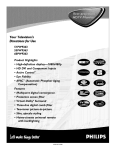
52C
SERIES
and 52P I
OWNER'S
PACKAGED
MANUAL
TERMINAL
AIR CONDITIONERS
AND HEAT PUMPS
7,000-15,000 Btuh
CONTENTS
GENERAL
.......................................
UNIT INSPECTION .............................
FRONT PANEL ................................
ELECTRICAL DATA ..............................
ALL UNITS ....................................
VOLTAGE SUPPLY .............................
INSTALLATION ................................
CHASSIS INSTALLATION ......................
WALL THERMOSTAT INSTALLATION ...........
OPERATION ..................................
COMFORT CONTROLS .........................
OPERATING CONTROLS ......................
OPERATING MODES ..........................
Page
2
2,3
2
4
4
4
5-8
5
8
CARE AND MAINTENANCE
.................
INDOOR-AIR INLET FILTERS ..................
EXTERNAL PARTS ............................
INTERNAL PARTS ............................
PREVENTATIVE MAINTENANCE ................
TROUBLESHOOTING ...........................
ACCESSORIES ..................................
Page
11,12
11
12
12
13
14
15
9,10
9
l0
l0
1.800.894,'6449
(in USA and Canada)
For Service/Technical
Assistance
1°800.830.8600
(Mexico)
Book
Manufacturer z_-_.ervesthe right to discontinue, or change at any time, speciflcalUon s or designs without notice and without incurrln 9 obligations.
1
4
PC 132
Catalog No. 535-20066
Printed in U.S.A.
Form 52C,P-2SO
Pg 1
10-04
Replaces: 52C, P-1 SO
GENERAL
with all accessory
components.
on page 15 for complete listing
Thank you for choosing
Carrier! You can feel confident
in your selection
because the same pride in craftsmanship and engineering
knowledge
that goes into Carrier
equipment
at the Astrodome
in Texas, the Sistine
Chapel
in Rome, the US Capitol Hall of Congress,
and
thousands
of other installations
worldwide
has gone
into the construction
of this unit.
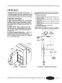
UNIT INSPECTION
The Carrier
package terminal
air conditioners
and
heat pumps provide a high standard
of quality in performance,
workmanship,
durability
and appearance
as
they heat and cool the occupied air space year round.
This manual
provides
information
for ease of installation, operation
and maintenance
of the 52C and 52P
units. The following units are covered in this manual
(see Figure
1 for additional
unit information):
52CE
52CQ
52PE
52PQ
52PC
60
60
60
60
60
Hz
Hz
Hz
Hz
Hz
cooling with electric heat
cooling, electric heat, and
cooling with electric heat
cooling, electric heat, and
cooling only units
units
heat pump
units
heat pump
units
units
All models are designed
for through-the-wall
installation. Separate
installation
instructions
are included
Examine
unit for damage
File a claim immediately
damage
is found.
See Accessories
of accessories.
incurred
with the
during
transit
section
shipment.
company
if
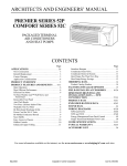
The data information
plate (Figure
1) lists the model
number, voltage ranges, and other important
electrical
information
about this product.
Reading
and understanding
this material
is important
for proper use of
this unit. To access the information
plate, the front
panel must be removed; see Figure 2.
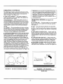
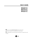
FRONT
PANEL
Remove front panel from unit by grasping
the panel
firmly at the center top and center bottom. Pull the
panel upward
at the bottom and forward at the top to
release magnetic
latches and partition
hooks. See
Figure 2.
NOTE: Front panel may be secured to chassis with
2 screws located behind indoor air inlet filters. In order
to remove these screws, the filters must be removed
first. Refer to page 11 in this manual for instructions
on
removing
indoor air inlet Filters.
IMPORTANT:
The front panel has to be off the unit
to complete
future checks and installation
procedures. Do not reinstall
front
panel at this time.
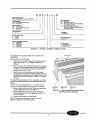
Using Figures
1 and 3 as reference,
verify that the
packaged
terminal
product
ordered will operate properly in your facility. If you do not understand
the information
given or have questions
about the product,
please call your local dealer or distributor.
FIGURE 2 -- REMOVING
MADE
IN
M_ICO
_212
_
D
FOR SERVICE/TECHNICAL
i
ASSISTANCE IN THE UI5. g_
CANADA
TELEPHONE
1-800-894-6449
IN MEXICO TELEPHONE
01-800-830-8600_
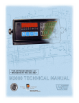
FIGURE
1 -- SAMPLE
DATA INFORMATION
PLATE
FRONT PANEL
Replacement Package Terminal Air Conditioner,
CLASSIFIED BY UNDERWRITERS
LABORATORIES INC., AS TO ELECTRIC
SHOCK, FIRE AND CASUALTY
HAZARDS ONLY. FOR FIELD
INSTALLATION WITH EXISTING
WALL SLEEVES, OUTDOOR LOUVERS, AND INDOOR PANELS AS
SPECIFIED ON THE PRODUCT.
S
52
Series Designation
PTAC (Packaged Terminal Air Conditioner)
PE
A
T
3
12
AA
Chassis Options
AA - Standard
CP - Corrosion Protection
RC - Wall Thermostat Control (Not available
on cooling only units)
RP - Wall Thermostat Control with
Corrosion Protection (Not available on
cooling only units)
Comfort Series
CE - Cooling with Electric Heot
CQ - Heat Pump
Premier Series
PC - Cooling Only
PE - Cooling with Electric Heat
PQ - Heat Pump
Latest Revision
A-Z
Electric
2 - 2.3
3 - 3.4
5 - 5.0
Packaging
I - Domestic
Heater Size
kW
kW
kW
Non-Performance
Changes 0-9
Cooling Capacity (nominal)
07 - 7,000 Btuh
09 - 9,000 Btuh
12 - 12,000 Btuh
15 - 15,000 Btuh
Electrical Data
3 - 230/208-v, 60 Hz
4 - 265-v, 60 Hz
FIGURE 3 -- MODEL NUMBER NOMENCLATURE
To install the front
lined below:
panel,
follow
the procedure
out-
TOP PARTITION
Replace the unit front panel.
1, Hold the front panel firmly at the center top and
center bottom at a 5 to 10 degree angle from
vertical.
2.
Place the top of the front panel onto the unit making sure the top engagement
posts have engaged
the slots on the unit. Front panel should be fiat
against
the top of the unit.
3. Gently lower the front panel onto the chassis,
ensuring
that the power cord (or conduit) is routed
through
the front panel notch. Magnetic
latches at
bottom of front panel will secure the front panel to
the unit.
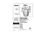
To install locking feature
panel is already installed
below:
NOTE:
screws
on front panel, be sure front
on unit and follow the steps
Two field-supplied
no. 8, Vz-in. sheet metal
are required to secure front panel to chassis.
1. Remove both indoor air inlet filters to expose
panel engagement
holes. See Figure 4.
2.
front
Secure front panel to chassis by attaching
the
field-supplied
screws into engagement
holes, Do
not over tighten.
3. Replace both indoor air inlet filters.
NOTE: Front panel alignment
may have
adjusted
slightly to line with chassis.
to be
DISCHARGE
DECK
ENGAGEMENT
HOLE
FRONT
SLOT
PANEL
FIGURE 4 -- FRONT PANEL INSTALLATION
WITH LOCKING FEATURE
ELECTRICAL DATA
ELECTRICAL
DO NOT
extension
unit may
SHOCK
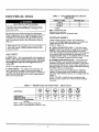
TABLE 1 -- SUGGESTED BRANCH CIRCUIT
WIRE SIZES*
HAZARD
alter cord or plug, and DO NOT use an
cord. Personal
injury or damage to the
result.
16,1 to 24
10
LEGEND
VOLTAGE
SUPPLY
Check voltage supply at outlet. For satisfactory
results,
the voltage range must always be within
ranges found on the data information
plate
(shown in Figure
1).
265-v
sub-
m WIRE SIZE -- Use recommended
wire size given in
Table 1 and install a single branch
circuit. All wiring
must comply with local and national
codes. All units
are designed
to operate
off single
branch
circurs
only.
• POWER CORD PROTECTION
-- The power cord
for the 230/208-v
unit provides
both personal
shock
protection
and power cord F_re prevention.
Unit power
automatically
disconnects
when unsafe conditions
are
detected.
Power to the unit can be restored
by pressing
the RESET
button on plug head.
Upon completion
of unit installation
for 230/208-v
models, an operational
check should be performed
using the TEST/RESET
buttons
on the plug head. See
Figure 5.
NOTE: The 265-v models do not incorporate
this
feature
as they require use of the electrical
subbase
accessory.
only.
I GROUNDING
-- For safety and protection, the
unit is grounded through the service cord plug or
through separate ground wire provided on hardwired
units. Be sure that the branch circuit or general purpose outlet is grounded.
TABLE 2 -- RECEPTACLES AND FUSE TYPES -- 250,265 VOLTS
RATEDVOLTS
TIME-DELAYTYPE
FUSE (or HACRCircuRBreaker)
the
l CORD-CONNECTED
UNITS -- The 250-v fieldsupplied
outlet must match the plug for the standard
208/230-v
units and be within reach of the service
cord. The standard
cord-connected
265-v units require
an accessory
electrical
subbase
for operation.
See
Accessories
table, page 15, for subbase selection.
Refer
to Table 2 for proper receptacle
and fuse type.
ALL UNITS
NOTE: Use copper conductors
AWG WIRE SIZEt
14
12
AWG -- American Wire Gage
*Single circuit from main box.
"i'Basedon copper wire at 60 C temperature rating.
Be sure that your outlet matches
the appropriate
blade configuration
of the supplied
plug and that it is
within reach of the service cord. A hardwire
kit is
available
as an accessory
to change cord-connected
units to hardwired
units. (See Accessories
table on
page 15.)
IMPORTANT:
All standard
cord-cormected
units will require a field-installed
electrical
base accessory.
NAMEPLATE AMPS
7.0 to 12
12.1 to 16
15 Amps
260
20 Amps
250
30 Amps
250
15 Amps
265
20 Amps
265
30 Amps
265
15
20*
30
15
20
30
LEGEND
HACR -- Heating, Air Conditioning, Refrigeration
*May be used for 15-amp applications if fused for 15 amp.
INSTALLATION
CHASSIS
INSTALLATION
Units are shipped
without
a sleeve. In applications
where unit is a replacement,
it is recommended
that a
Carrier
sleeve and grille be used.
The 52C and 52P units can retrofit
General Electric,
Amana, Trane, and Friedrich
sleeves/grilles
(be sure
outdoor grille is installed
on the sleeve). See Table 3
for details.
Carrier
Corporation
must approve
any
other retrofit
application.
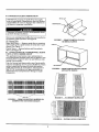
For competitive
retrofit applications,
be sure that the
foam seals (factory-installed
on the tube sheets) provide a good seal between
the outdoor
grille and outdoor coil tube sheets. These foam seals provide a
barrier
to separate
outdoor coil leaving air from mixing with the outdoor
incoming
air (knov, m_as air recirculation).
See Figure 5.
For retrofit
applications,
foam seals on outdoor coil
tube sheets must make a seal between
the coil and
the grille or loss of performance
and premature
damage
to the major components
can result.
TABLE 3 -- RETROFIT WALL SLEEVES
MANUFACTURER
General Electric
Amana
Trane
Friedrich
WALL SLEEVE PART NUMBER
Metal Sleeve RAB71
Plastic Sleeve RAB77
Metal Sleeve WS900B
Metal Sleeve BLV149
T-Series Metal 111/2-in. deep wall sleeve*
Standard depth wall sleeve 16 x 42 x 133/4-in.
PXWS
*FR-SLEEVE-EXT accessory is required for retrofit into Friedrich
(T-Series) wall sleeves,
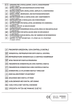
INDOOR-AIR
INLET
FILTERS
DISCHARGE
GRILLE
WIRE SCREEN
OUTDOOR
ORIFICE
COIL TUBE
SHEETS
INDOOR
COIL
PLUG TEST/
RESET BUTTONS
FRONT
PANEL
FIGURE
5 -- UNIT
COMPONENTS
BASEPAN
OLRDOOR
GRILLE
WALL
SLEEVE
•
COMPETITIVE
SLEEVE
PREPARATION
METAL CLIP
IMPORTANT:
Inspect the wall sleeve thoroughly
prior to installation.
Manufacturer
does not assume
responsibility
for costs or damages
due to defects in
the sleeve or improper
installation.
Disconnect
all power to unit to avoid
cal shock during installation.
possible
MOUNTIN(
electri-
Remove any existing
foam baffles that are installed
the outdoor
grille ff present.
See Figure 6.
GE Sleeves Only
on
FIGURE 7 -- REMOVE METAL CLIP ON
GE METAL SLEEVE
Metal Wall Sleeve -- Remove metal clip on mounting
rail located on left, inside bottom of metal sleeve and
discard. See Figure 7.
Plastic Sleeve -- Remove bottom seal from plastic
sleeve. See Figure 8.
•
INSTALLATION
OF A CARRIER WALL SLEEVE
USING A NON-CARRIER
GRILLE
This application
has become more common due to
pre-manufactured
windows
with built-in
grilles or renovations where a Carrier
sleeve is used with an existhag non-Carrier
grille.
Use of a Carrier
wall sleeve with a non-Carrier
grille
requires
installation
of an Accessory
Baffle Kit, which
ensures
a good seal between
the unit and exterior
grille and prevents
air recirculation.
(See Figures
9
and 10.) Air recirculation
is a large contributor
to
performance
loss and premature
damage to major
components.
BAFFLES
FIGURE 6 -- REMOVE
EXISTING BAFFLES
COMPETITIVE
OUTDOOR
GRILLES
BOITOM SEAL
FIGURE
8 --
REMOVE
BOTTOM
GE PLASTIC
SLEEVE
SEAL
FROM
FIGURE 9 -- ACCESSORY BAFFLE KIT
ON
FIGURE
10 -- INSTALLATION
COMPLETE
•
INSTALL CHASSIS IN SLEEVE (See Figures 11 to
13)
1. Inspect foam gaskets (top, bottom, both sides) on
chassis. Replace foam gaskets ff torn or missing.
SIDE
GASKET
TOP
GASKET
FACTORY*INSTALLED
FOAM SEALS
IMPORTANT:
The gaskets combine with the sleeve
face to create a weather
barrier.
If the chassis is
installed
in a non-Carrier
sleeve, this weather
barrier may not be effective.
Chassis weighs up to 150 lb, For personal
seek help when lifting the unit. Lift unit
unit basepan.
protection,
by holding
2.
If retrofitting
into a GE, Amana, Trane, or
Friedrich
wall sleeve/grille,
remove any ex!sting
foam seals from competitive
manufacturer
s grille
before installing
unit.
3. Remove shipping tape from vent door. See Figure 11.
Failure
to remove shipping
air vent door from opening
to the vent door cable.
COILTUBE
SHEETS
GASKET
FIGURE 12 -- UNIT GASKETS
AND TUBE SHEETS
tape will prevent
fresh
and may result in damag_
4.
Carefully
remove power cord packing
and discard.
5. Lift chassis level with wall sleeve.
material
6.
Slide chassis into wall sleeve until foam gaskets
rest firmly against
front of wall sleeve. See
Figure
12.
7. Screw chassis to wall sleeve with four 13/tin. long
screws taped to the control box. Screw holes are
located on both sides of the mounting
angles of the
chassis.
For Carrier
wall sleeves, use the top-mast
and bottom-most
screw holes, For competitive
wall sleeves, line up the correct attachment
holes
on the chassis with the holes in the sleeves. See
Figure
13.
MANUFACTURER
SLEEVE
ATFAGHMENT
HOLE
(CARRIER SLEEVE)
FIGURE 13 -- CHASSIS
VENT
DOOR
FIGURE
11 -- LOCATION
ON VENT
SHIPPING
TAPE
OF SHIPPING
DOOR
VENT DOOR
CABLE
TAPE
MOUNTING
WALL
THERMOSTAT
The following instructions
only.
NOTE: Carrier
thermostats
Accessories
section.
INSTALLATION
apply
to RC and laP units
are recommended.
See
IMPORTANT:
Only trained,
qualified
personnel
and service mechanics
should install electrical
accessories
on Carrier
52C and 52P series products
per Carrier's
installation
instructions.
Please contact your local electrical
contractor,
dealer, or distributor
for assistance.
4.
Reinstall
terminal
connector.
5. Restore power to unit.
NOTE: Refer to thermostat
installation
instructions
for details on installing
thermostat.
NOTE: Fan speed is userLselectable
from the control
panel on the unit.
• THERMOSTAT
WIRE ROUTING
-- Thermostat
wire is field supplied.
Recommended
wire gage is 18 to
20 gage solid thermostat
wire. Thermostat
wire should
always be routed around or under, NEVER through,
the wall sleeve. The wire should then be routed behind
the front panel to the easily accessible
terminal
conhector. See Figures
14 and 15.
• INSTALL
units.
I.
2.
THERMOSTAT
Check to be sure power
Pull terminal
connector
-- All remote
/
control
to unit is disconnected.
to remove.
NOTE: Terminal
connector
can be removed
and replaced to simplify thermostat
wiring.
3. Connect wires from terminals
on the thermostat
to terminals
on chassis terminal
board connector.
See Figures
15 and 16.
SELECTOR
SWITCH
FIGURE 15 -- TERMINAL
CONNECTOR
REMOVAL
AND REPLACEMENT
TERMINAL
CONNECTOR
m
..-(_ G
_Y
TYPICAL
WALL
THERMOSTAT
O _-SEE
NOTE #I
._
THERMOSTAT
WIRE (FIELD
SUPPLIED)
TERMINAL
BLOCK
NOTES:
1. Use terminal "O" for heat pump connection only.
2. Terminal C (common) Jstypically only required for digitalthermostats
3. See table below forterminal descriptions,
CORD
FIGURE 14 -- CONTROL BOX TERMINAL
CONNECTOR FOR WALL THERMOSTAT MODELS
C _--SEE
NOTE #2
TERMINAL
FIGURE
DESIGNATION
R
24 VAC
G
Fan
Y
Compressor
W
Electric Heat
O
C
Reversing Valve
Common
16 -- WIRING
CONNECTIONS
OPERATION
IMPORTANT:
When unit is first started,
high
humidity
conditions
can cause condensation
to form
on discharge
grille. Keep doors and windows closed.
Room humidity
decreases
and moisture
evaporates.
The temperature
limits are factory set to full range,
which is 60 F to 90 F. To set restricted
rotation
of the
temperature
control knob:
1. Remove front panel.
2.
COMFORT
CONTROLS
3.
• ADJUST AIRFLOW
DIRECTION
-- The discharge
air grille is mounted
on the front panel so that the air
discharges
forward.
If upward
discharge
is required,
remove the grille by removing
screws on back of front
panel. Rotate grille 180 degrees and reinstall
on the
front panel.
• ADJUST VENT -- The vent handle is on the left
side of the unit. Turn handle to open or close vent.
Vent will remain in last desired position until handle
is turned
again. Magnet will ensure positive closure.
See Figure
17.
4.
5.
6.
7.
Remove temperature
perature
limiter.
Remove standoff pins
cator holes.
Replace standoff pin
temperature.
Replace standoffpin
temperature.
Reinstall
temperature
Reinstall
front panel.
control
knob
to expose
from the 60 F and
90 F indi-
in bole for desired
minimum
in hole for desired
maximum
control
knob.
NOTE: Temperature
indicators
stamped
on temperature limiter are approximate
and represent
degrees E
• SETTING
TEMPERATURE
LIMITS -- Setting temperature
limits on the unit provides
the user a
restricted
range of temperature
control. See Figure
18.
NOTE: This adjustment
is optional
ble to remote control units.
o
and is not applicaTEMPERATURE_
CONTROL
STANDOFF
PJNS
FAN CYCLE-SWITCH
j"
©
i
®
i I
i
©
VENT HANDLE
SCHE,ATIC[
i
MAGNET
ELEC'_,__
SCREW
SET
\
OUTDOOR
THERMOSTAT
{HEAT PUMP
UNITS ONLY)
VENT
DOOR
FIGURE
J II !
VENT "
FILTER
17 -- VENT
DOOR
tem-
FIGURE
18 -- OPERATING
CONTROLS
OPERATING
CONTROLS
IMPORTANT:
If setscrew
on standard
heat pump
unit is set to electric heat mode operation,
the compressor is disabled
for both heating
and cooling
operations.
If setscrew
on heat pump unit with wall
thermostat
control is set to electric heat mode
operation,
the compressor
will be disabled
only for
heating
operation.
The following controls
are located on the front of the
control box door, under front panel. To obtain access to
operating
controls,
remove the unit front panel as
shown on page 2. See Figure 18.
• FAN CYCLE SWITCH -- (Typically
available
at
wall thermostat
on RC or RP units.) This allows the
fan to operate
in two modes:
CON (Continuous)
-- This setting
allows the fan to
run continuously,
circulating
air even when the temperature
setting has been satisfied.
This switch helps
to maintain
the room temperature
closer to the ther*
mostat setting.
Use this switch position
when maximum comfort is desired. This is the factory default
setting.
CY_C C(vcle) -- This setting allows the fan to cycle on
off with the compressor
during heating
or cooling.
The fan stops when the temperature
setting is satisfied. This results
in longer unit off-time and wider
variations
in room temperature
and humidity.
OPERATING
and
•
OFF -- The OFF
19
mode
terminates
unit
operation.
• HIGH HEAT OR HIGH COOL -- Select mode and
rotate temperature
knob to desired comfort level. This
function provides maximum heating or cooling, and is
recommended to raise or lower the room temperature
quickly.
• LOW HEAT OR LOW COOL -- Select mode and
rotate temperature
knob to desired comfort level. This
function
provides
minimum
heating
or cooling with
maximum
dehumidification
and quietest
operation.
• FAN SPEED CONTROL FOR 52P AND 52C WALL
THERMOSTAT MODELS -- For maximum comfort,
fan speed is user selectable at the unit. See Figure 20.
MODE
FAN
t.,_ 17 -,',
/t j/
WALL
_AR_ER
Figures
• FAN-- The FAN mode will circulate air in the space
at high speed and at high or low speed for cooling only
models.
_F
Premier
(See
• OUTSIDE AIR -- To bring outside air into occupied
space, turn the vent handle to the full open position.
See Figure 17.
• OUTDOOR
THERMOSTAT
(52CQ and 52PQ HEAT
PUMP UNITS ONLY) -- If the setscrew
is left at the
factory setting
(in the heat pump position),
the unit
will operate
in the reverse cycle heating
mode. See
Figure 18. When the temperature
of the outdoor coil
reaches
20 F (approximately
35 F outdoor air temperature), the compressor
will shut down as unit is no
longer capable of adequate
heating
in heat pump
mode. The electric heater then becomes
the primary
heating
source. The electric heater remains
on until
the temperature
of the outdoor coil reaches
40 F; then
the electric heater
is shut off and the compressor
is
energized.
Once the compressor
is energized,
the heat
pump again becomes the primary
heating
source.
To set unit to operate in electric heat mode only, turn
the setscrew
to the electric heat position. See Figure 18.
TEMPERATURE
MODES
g0.)
COOLER
]-aEAT
•
FAN
_
THERMOSTAT
a
IP|ED
-
COMFORT
COOL
Series
I
FIGURE
19 -- 52P UNIT CONTROLS
FIGURE 20 -- 52P UNIT WITH
WALL THERMOSTAT CONTROL SHOWN
(Blank Plate)
SHOWN
10
CARE AND MAINTENANCE
In order to maintain
proper performance
of your pack
aged terminal
air conditioner
or heat pump, it is very
important
that the fan and outdoor coil, the blower
wheel, blower scroll, electric heater, and all drain passages are thoroughly
cleaned at least once per year.
Carrier
recommends
that as a minimum,
the cleaning
should be conducted
prior to the start of each heating
season. The air inlet Filters should be cleaned
every
month.
Depending
on local conditions,
more frequent
cleaning
of the unit may be required
to ensure optimum performance and long operating
life. Examples
of these special conditions
include areas where construction
dust
or heavy airborne
dirt is found, or environments
that
promote
the growth of fungus.
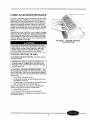
FIGURE 21 -- INDOOR-AIR
FILTER REMOVAL
Some local conditions
and environments
can cause
fungi to grow inside the air conditioner,
especially
on
indoor blower section. Dried fungi, dirt and other
foreign material
are fire hazards.
Be sure to clean
unit according
to the instructions
that follow.
INDOOR-AIR
• INDOOR-AIR
once each month.
INLET
INLET
FILTERS
FILTERS
should
be cleaned
IMPORTANT:
Filters may become clogged if not
cleaned properly.
Clogged filters will restrict
airflow which may lead to severe component
damage
and efficiency
loss,
• CLEANING
INDOOR-AIR
INLET FILTER -- Two
interchangeable
air filters are located on the backside
of the front panel. Each can be removed
and cleaned
one at a time. To remove and clean the filter, follow the
steps below:
1. Grasp Filter with both hands.
2. Gently pull the Filter up and away from the unit.
See Figures
5 and 21.
3. To clean filter, use a vacuum or soft bristle brush
with a small amount
of mild detergent.
NOTE: If detergent
is used, remove any detergent
residue with a gentle stream
of clean water.
4. Allow Filters to air dry.
5. Re-insert
dry filters back into front
Additional
Accessories
filters are available
section.
panel.
in multi-packs.
Refer to
11
INLET
EXTERNAL PARTS
VENT HANDLE
• EXTERNAL
PARTS include the polymer
sleeve and
grilles. The sleeve manufacturer
recommends
cleaning
the surface, including
the grilles, with household
detergent
and water.
MAGNEt
INTERNAL PARTS
• INTERNAL
PARTS should be cleaned at least once
during the year. The outdoor vent triter should be
cleaned at least once during a cooling or heating
season.
Internal
parts that should be cleaned include
lowing (see Figures 5, 22, and 23):
Outdoor
vent filter
Basepan
Outdoor
orifice and fan
Indoor and outdoor refrigeration
coils
Indoor blower wheel
Wire screen
Scroll
Wall sleeve internal
surfaces
Outdoor
grille
the fol-
VENT
DOOR
VENT.
FI_ER
FIGURE 22 -- OUTDOOR VENT FILTER
(Left Side of Chassis)
i
o
"b-SCROLL
WHEEL
FIGURE 23 -- BLOWER WHEEL AND SCROLL
12
PREVENTATIVE
MAINTENANCE
Preventative
maintenance
is essential
to proper unit
operation,
efficiency
and longevity. To assure
equipment operates
properly
it must be properly maintained. Equipment
operation
should be checked and
verified several times during each year.
During regular
unit inspection
and maintenance,
follow the guidelines
below:
Wash both sides of outdoor coil
Wash basepan
and outdoor vent filter
Wash the indoor coil
Clean the blower wheel and front panel
Clean or install new indoor-air
inlet filter(s)
Ensure knobs are secure and operable
Inspect cord and receptacle
Secure electrical
connections
Ensure front panel is properly
mounted
and not
damaged
• Ensure wall sleeve is installed
properly
• Ensure heat and cool cycles operate properly
• Check power cord protective
device by pressing
the
TEST button, then pressing
the RESET button.
13
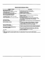
TROUBLESHOOTING
POSSIBLE CAUSES
UNIT DOES NOT START
• Unit may have become unplugged
• RESET button on cord or plug may have tripped
• Fuse may have blown
• Circuit breaker may have been tripped
• Unit mode dial may be set to the OFF position
UNIT NOT COOLING/HEATING ROOM
• Unit air discharge section is blocked
• Temperature setting is not high or low enough
• Unit air filters are dirty
• Room is excessively hot or cold when unit is started
• Vent door left open
UNIT MAKING NOISES
WATER DRIPPING OUTSIDE
WATER DRIPPING INSIDE
• Wall sleeve is not installedlevel
ICE OR FROST FORMS ON INDOOR COIL
• Low outdoor temperature
• Dirtyfilters
SOLUTIONS
•
•
•
•
•
Check that plug is securely in wall receptacle.
Check RESET button on cord or plug. See Note 1.
RepLacethe fuse. See Note 1.
Reset circuitbreaker. See Note 1.
Switch mode dial to an operating mode.
• Make sure that curtains, blindsor furniture are not restrictingor
blockingunit airflow.
- Reset to a lower or higher temperature setting.
- Remove and clean filters.
• Allow sufficientamount of time for unit to heat or cool the room.
Start heating or cooling early before outdoortemperature, cooking
heat or gatherings of people make room uncomfortable.
• Close vent door.
• Clicking, gurgling and whooshingnoises are normal duringoperation of
unit.
• If a drain kit has not been installed,condensation run-off during
very hot and humid weather is normal. See Note 2. If a drain kit
has been installedand is connected to a drain system, check
gaskets and fittingsaround drain for leaks and plugs.
• Wall sleeve must be installed level for proper drainage of condensation.
Check that installationis level and make any necessary adjustments.
• When outdoortemperature is approximately 55 F or below, frost
may form on the indoor coil when unit is in Cooling mode. Switch
unit to FAN operation until ice or frost melts.
• Remove and clean filters.
NOTES:
1. If circuit breaker is tripped, fuse is blown or RESET button on cord or plug is tripped more than once, contact a qualified electrician.
2. If unit is installed where condensation drainage could drip in an undesirable location, an accessory drain kit should be installed and connected to
drain system.
14
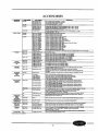
ACCESSORIES
ACCESSORY
Wall Si_'ves
FORM NUMBER
PART NUMBER
OIESCRIPTION
52S-48SI
WALL-SLEEVE-1 PK
WALL-SLEEVE-gPK
SLEEVE-INSUL=I PK
Non Insulated Polynmr Waft Srse_,_, 1 pe_ pad<
Non Insulated Polep_r wall Slee,,_, 9 per pack
Insulated Pol_ner Wall S_ee,,e, 1 Per pack
52S-50SI
SLEEVE-STEEL-1
Insulated Mebd Wall Siee'_, 1 per pack
52S-49SI
SLEEVE-EXT24-1 PK
SLEEVE-EXT26-1 PK
SLEEVE-EXT28-1 PK
SLE EVE _4OLDING
Extended Metal Wall Sleeve for Deep Wail Applications (24 in. deep), 1 per pack
52C,P-26SI
FR SLEEVE-EXT
Friedrioh wall sleeve extension to tet rord Career PTAC unit into Friedrich 111/2_deep
Series_ wall slee'_. 1 per pack
52S-5SSI
52S-65SI
GRILLE-ALU-STAMP
Stamped Aluminum Exterior Gdlle, Clear Fingsh
GRILLE-PLA-BROWN
GRILLE-FLA-BEIGE
52S_o0SI
G RILLE-ALU _,LEAR
GRILLE=ALU-WHITE
GRILLE-ALU_RONZ
GRILLE-ALU_fBRNZ
GRILLE-ALU_ROWN
GRILLE-ALU-BEIGE
GRILLE-ALU -ALPIN
GRILLE-ALU4_EACH
GRILLE-ALUMELON
GRILLE-ALU-LGREY
GRILLE-ALU-SGREY
GRILLE-ALU-RDBRK
GRILLE-ALU-BLUE
GRILLE-ALU_3REEN
Polymer Architeclural Rear Grille, Brown
Polymer Architectural Rear Grllio, Beige
Aluminum AtchRactural Exterior Grille, Clesr Finish
Aluminum Architectural Exterior Grille, White
Aluminum Architectural Exterior Grille, Light Bronze
Aluminum Architectural Exterior Gdlie, Medium Bronze
Aluminum Architectural Exterior Grille, Brown (Dark Bronze)
Aluminum Architectural Exiefior Grille, Rei_=gee
Aluminum Archit_:t LWal Exterior Gririe, AJlffne (matches Carrier Wall Slee_s)
Aluminum Architectural Exlerio¢ Grille. Poach
Aluminum Architectural Exterior Grilie, Melon
Aluminum Architectural Exterior Grille, Light Grey
Aluminum Architectural Extedor Grille, Slate Gray
Aluminum Architectural Extedor Grille, Red Brick
Aluminum ArctlitecturaJ Exlerior Gdlle, B_ue
Aluminum AndlitechJral Extedor Gdlle, Green
52C, P-31SI
BAFFLE KIT-I PK
52C, P-1SI
SUBBASEJqON-ELEC
52C, P-2SI
SUBBASE-23OV-15A
SUBBASE-23OV-20A
SU_ASE-230V-3OA
52C,P-17SI
SUBBASE-265V-15A
SU BBASE-265V-20A
SUBBASE-265V_3QA
52C.P_3SI
SUBBASE-HARDWIRE
52C,P-4SI
SUBBASE-SWITCH
52C,P-5SI
SUBBASE-FUSE-15A
SUBBASE-FUSE-20A
SUBBASE-FUSE-30A
52C,P-11SI
HARDWIRE-KIT-1 pK
52C,P-19SI
CON DU IT-INTF-4PK
Interface kit for F,eld-supplied conduit to provide perrnarmnt pov_r con_c_on
230/208V and 265V) to the unit. Witincludes Molex connector for easy connect/disconnect.
4 per pack
Condensm
Drain Kit
52S-53SI
DRAIN-KIT-4PK
Attaches to wall s_eevefor cent rc4ledinternal Oreedernal disposal of condensate 4 per pack
Wa|
Then'nostats
N/A
HHQ1AD045
TSTATCCBFC01 -B
TSTATCCBPH01 -B
TSTATCCPAC01 -B
TSTATCCPH P01-B
52C,P-30SI
RC_FIELDKIT230HC
Eiectro-mechan_aJ Wall Thermostat (Heat/Cool and Heat Pump)
"v_lue S.mie s Electronic Thenmostat w/Digital disptay (Heat/Cool Mode_s)
Value Redes Electro_io Thermostat w_Digital dispfoy (Heat Pump Modeio)
7 Day Programmable _eckonic Thermostat (H
Heat/Cool Models)
7-Day Programmepfo Bectronio Thermostat (Heat Pump Modets)
F]ald_nstalled v_ll therraostat retrofit kit to co*wed • standard 230V Heat/Coot unit to an
RC unit. Wall _ermostat sold separately (can be used to convert a cool only unit to RC).
F]eld-instalied wall thermostat reoofit Idt to co_lvert a stanc_'d 230V Heat Pump unit to an
RC uniL Wall thermostat sold separatel_
Fiald_nstalled wall thePmostat re_o_ kit to COT_ert a standard 265V Heat,_ool unit to an
RC unit. Wall thermostat sold separately (can be used to convert a cool only unit to RC).
F_eld_nstalled wall thermostat retrofit kit to convert a standard 265V Heat Pump unit to a
RC unit. Wall thermostat so_d separately.
Exterior Grilles*
SubbaSe
Subbsse
Field-installed
Kits
FJectdcal
Cmlnection$
WaB lltermost
at
interface
Retrofit lot
PK
RC-F}ELDKIT230HP
RC'FIELDKIT265HC
RC-FIELDKIT265HP
Exteflded Metal
Metal Wall
Woll Sleeve
Sleeve for
for Deep
Deep Wall
Wall App_ioations(28
Appti_tJons (26 in.
in. dsep,
deepl, 1
1 pe_
_ pack
pack
Extended
Maldir_j kit to tdm the wall slee_ to the wall
Ensures good air seal and prevents air recimulation when Carrier sle_e
Non-electrical Subbase
Eiec_cal
Electrical
Electrical
Electrical
Electrical
Electrical
is used with a non-Cartier grille.
sub/ease with Pactoq¢4natalled 208/230V, 15 amp m_ie
sut_ase with _actory_nstabed 20_230V, 20 amp receptacle
sut_ase with factor_4nstabed 20_/230V, 30 amp m4_p_de
sul_ase with factoP/-installed 265V, 15 amp receptacle
sutYoase with facforT-installed 265V, 20 amp mceptaale
su_oase with fac_or_-ins_alied 265V, 30 amp receptaole
Eleci_ical subbase with _actor_nstalled
hardY€irakit (230/208V and 265V)
Field-lnataliebfo Switch Idt for an eiecttioal subbase
Field-Installed Fuse
Fuse Kit
Kit ((15
ampl for
for electrical
electrical sut_ase
sol'case
Fleld-lnstalied
_0 amp
Field-Installed Fusm Wat(30 amp) for eleckical subbase
Permanent power connec_on to the unit (inctudes 36"of flex_oleconduit and urdFmounted
connector, 230/208V and 265V) 1 per pack
52C,P-34SI
N/A
2 SPE ED-TSTAT-KIT
Field_nstalled automaSc heat/ccol chan_eo'_r theneost,M with 2mpeed fan conilot at thermostat.
TSTAT-COV ER-6X7
C_ear I_astlc ioddng thermostat cover pm'_nts unauthorized asoess te thermostaL
Ca_r for u_e with non_)rogrammabfo and eioc_'o-mech_nioal thermostats.
Outside dimensions: 6_/=* • 71/2_ x 21s/is_. 1 per Peck
N/A
TSTA%COV ER-TX 10
N/A
AIR-FILTE R-10PK
C;ear p_astic Ioddng thermostat cover'pnm_ents unauihor _zedaccess to thermostat. Cover for
use with pro_mrnable
thermostats. Outside dimensions: 7V4" • 9_/4_ x 3_/e'. 1 pe_ Peck
RepLacement air fiitem in pac_.age of 10
Energy
Mana_
L_:_n 9 Security
Control Do_
52C,P-24SI
EM-KIT
Allows unit to be turned on and off from a rF,mot e location (includes treeze guard protection)
52C,P-23SI
SECURITY-DOOR
Keyqocking security door to prevent aco_ss to beating and cock ng controls
Later_ Duct K_
52C,P-25SI
LATEP,AL-D UCT
Ductwork to allow one unit to heat and cool two rooms (pks_um plu_ extension duct and re_isters)
Power Vent
Ret_t
K_t
52C,P-32SI
PWR -VE NT_)OOR230
Power vent with au_rnatio door that opens and closes when the fan turns on and off (230V).
PWR-VENT-DOOR265
Power vent with automa_c door that opens and closes when the fan turns on and off (265V)
Air_urtaln
Deflector
52C,P-9SI
Dt_FLECTOR-1 pK
52C,P-21 SI
CUR3_FL-52CP
Lateral air deflecfor, with lndividuall), adjustable louvers, to eoffanos air circulatton, 1 Per
CurteJn deflector fer 52C and 52P models -- pre_mn_ curt_ns from _owing into
discha
air stream. 1 per pack.
NOTE:rg_ur rain de_lsctor for previous models am also ax-aitabte. Contac_ Carder Repmsenta_'_.
N/A
CARRIER-TOUCH-UP
Repl=:ement
Filters
Touch-Up Paint
*Custom _iors
1PK
Touch up paint for repeir_ng scratches or chips.
are also available.
15
.3
Carrier
Packaged Terminal
Air Conditioner Warranty
FULL ONE-YEAR WARRANTY -- During the first year after purchase, CARRIER
wJll, through tts authorized iodependent servicing deaiors or sen/ice stations*, and
free of charge to the user or subsequent users, rep,alr or repioce any parts which
are detective in material or workmanship. The replacement part can be a new or
remanufacturod part as providod at CARRIER'S sole option.
FULL EXTENDED FOUR-YEAR WARRANTY ON SEALED REFRIGERATION
SYSTEM ONLY -- Dudng the second through fifth years after date of original purchase, CARRIER will, through its authorized servicing dealers and sen/ice stations*
and free of cha e to the end user or subsequent users, repair or replace the
conr_-_nser,u,=
evaporator or connecting tubing if defective in matadal or
compressOr,workmanship.
This includes system refr_eration charge. The replacement part can
CARRIER WILL NOT BE RESPONSIBLE FOR:
1. CLEANING REQUIRED PRIOR TO WARRANTY REPAIR,
2 Standard maintenance, cleanln
or damage rasuRing from failure to perform
normal maintenance as outlineuin the owner's manual.
3. Instruction on methods of control and use of air conditioning unit after initial
installation.
4. Damage or repairs needed as a consequence of faulty installation or appllcarich. This is the responsibility of the installer.
be new or a remanufactured part as prowdod at CARRIER'S sole option.
LIMITED EXTENDED FOUR-YEAR WARRANTY ON NON-SEALED REFRIOERATION SYSTEM ONLY -- During the second through fifth years after date of odglna! purchase, Carrier will, through its authorized sewicing dealers and service
stations and free of charge to the end user or subsequent users, repair or replace
any non-sealed system part motor, solenoid, thermistor, thermostat, reteys, switch,
capacitor, overload, drain ve]ve, bulb heater, fan, stator) if detective In material or
workmanship. The replacement part can be new or a remanufactured part at
CARRIER'S sole option. THIS LIMITED WARRANTY DOES NOT INCLUDE
LABOR, user ts responsible for labor, Includiog cost of diagnosis of probtem,
removal and transportation of the air conditioner to and from the service center, and
reiostallation charges necessary to accomplish repair.
LIMITATION OF WARRANTIES -- ALL IMPLIED WARRANTIES (INCLUDING
IMPLIED WARRANTIES OF MERCHANTABILITY) ARE HEREBY LIMITED IN
DURATION TO THE PERIOD FOR WHICH EACH LIMITED WARRANTY IS GIVEN
AND APPLIES. SOME STATEE DO NOT ALLOW LIMITATIONS ON HOW LONG
AN fMPLIED WARRANTY LASTS, SO THE ABOVE LIMITATION MAY NOT APPLY
TO YOU. THE EXPRESSED WARRANTIES MADE IN THIS WARRANTY ARE
EXCLUSIVE AND MAY NOT BE ALTERED, ENLARGED, OR CHANGED BY ANY
DISTRIBUTOR, DEALER, OR OTHER PERSON WHATSOEVER.
6. Damage or
repairs needed
as a consequence of anY mlsapplicafion , abuse ,
.
,
unauthonzed altoration, improper servicing or operation.
7. Damage as a result of floods, winds, fires, lightnio , accidents, corrosive
environment, or other conditions beyond the control ofgCARRIER.
ALL WORK UNDER THE TERMS OF THIS WARRANTY SHALL BE PERFORMED
DURING NORMAL WORKING HOURS. ALL REPLACEMENT PARTS, WHETHER
NEW OR REMANUFACTURED, ASSUME AS THEIR WARRANTY PERIOD ONLY
THE REMAINING TIME PERIOD OF THIS WARRANTY.
5. Failure to start due to voltage conditions, blown fuses, open circug breakers
or
any other damages due to the inadequacy or interruption of electrical
services,
EXCEPTION TO CORROSIVE ENVIRONMENT IN ABOVE PARAGRAPH -Packaged
terminal
(52
buntwith
protection
are exempt
Packaged
terminal units
units
(52 Series
Series)Environment."
buntwith corrosion
corrosion
protection
exempt
from the exclusion
exclusion
-- =Corrosive
=Corrosive
The unit
model are
model
number
iss
identified on the
with
a
CP
suffix.
the nameplate
nameplate
suffix.
8. Reimbursement for replacement parts or repair services which are not supplied or designated by CARRIER and which are specifically covered
covered under
this warranty.
products
9. CARRIER
CARRIER
products installed
instaliod outside
outside the
the confinente{
confinente{ U.S.A.,
U.S.A., Alaska,
Alaska, Hawaii
Hawaii
and
Canada.
10.
11.
12.
Shippin_ damage or damage as a result of transporting the unit. This is the
responsibility of the selling dealer or the authorized Room Air Conditioner
service station.
ANY SPECIAL, INDIRECT OR CONSEQUENTIAL PROPERTY OR COMMERCIAL DAMAGE OF ANY NATURE WHATSOEVER. Some states do not
allow the exclusion or limitation of incidental or conssquenfial damages, so
the above limitation or exclusion may not apply to you.
Warranty coverage of accessory items (wall thermostats, wallsleeves, ete.).
NOTE: Service and Maintenance Items excluded in this warranty may be covered by
a separate service agreement through the seller at time of purchase.
*Authorized independent dealers or service stations ere registered with Carrier Air Conditioning through its distributor organization.
This warranty
Catalog No. 530-122 (Rev. 3/02)
gives you Specific
legal
rights, and you may also have other
rights which vary from state to state.
.3
L
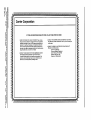
Carrier Corporation
IF YOUR AIR CONDITIONER
b-m
=8
DOES NOT WORK, FOLLOW THESE STEPS IN ORDER:
.o=_.
.===_
m
=.
3"m
eng.
1. CHECK THE THINGS YOU CAN DO YOURSELE These include
being sure the air conditioner is plugged in firmly in an appropdata
receptacle, checking the fuse or circuit breaker and ensudng its replacement or resetting, ff necessar/, and rereading the instruction
book to ensure that all controls are set properly. By doing this you
can save money. Many unnecessary service calls in the serviceman
doing what the owner can do for him or herself.
2. CONTACT YOU R DEALER OR THE RECOMMENDED CARRIER
AUTHORIZED SERVICE CENTER. They have been set up
to handle the great majority of all possible service problems, The
quickest, surest and best way to get your air conditioner back in
servkie Is to use this step before proceeding further.
3. CONTACT THE CARRIER DISTRIDUTOR SERVING YOUR AREA.
Your dealer can provide the distributor's name or you can consult your
yellow pages.
4. CONTACT CARRIER IF A SATISFACTORY SOLUTION IS NOT
REACHED IN STEPS 2 AND 3.
Carder Air Conditioning
Consumer Relations Depadment
Carrier Parkway, P.O. Box 4808
Syracuse, New York 13221
Telephone: 1-800-894-6449
3=
O_ _.
J
!00000000000000000000000=000000000000000000000000000000000
OOOOilOOOOOOOOOllOOOOOO
"o
o_
o
O°OOOOiO000O°|OOOl||°°°OOlOllll|lO
00!