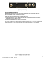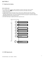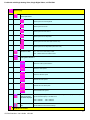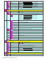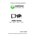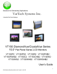
1
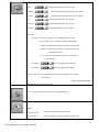
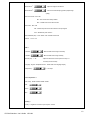
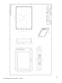
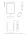
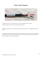
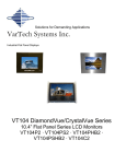
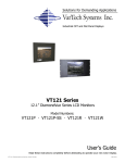
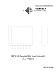
Solutions for Demanding Applications All Weather Series LCD Monitors VT150XB4 User’s Guide VT150 All Weather User’s Guide 150-184 1 Read these instructions completely before attempting to operate your new LCD Color Display. Table Of Contents Page Section 1 Introduction Page Section 4 Touchscreen 1.0 Overview 3 4.1 Touch Screen Introduction 14 1.1 VT150 General Features 3 4.2 Touch Screen Installation 14 1.2 Product Safety Precautions 3 Section 2 Display Setup Section 5 Troubleshooting 2.1 Inspection 4 2.2 Unpacking 4 2.3 Included Parts 4 2.4 Installation Guidelines 2.5 Video Input Connections 4-5 5.1 General 15 Section 6 Maintenance 6.1 Cleaning 16 Specifications 17 6 Section 3 Getting Started 3.1 Adjusting the display 3.2 OSD Adjustments 7 Mechanical Drawings 18-19 8-13 VT150 All Weather User’s Guide 150-184 2 INTRODUCTION SECTION 1 1.1 Overview VarTech All-Weather series includes waterproof, totally sealed, IP67 NEMA 6 LCD displays. These high resolution, sunlight readable LCD displays provide exceptional clarity, viewing angles, extensive operational temperatures (-40°C to +70°C), IP67 (NEMA 6) protection, and offer durable, 5-Wire, resistive touch screens. 1.2 VT150 General Features o o o o o o o o IP67 Fully Enclosed LCD Rugged Machined 6061 T6 Aluminum Enclosure Solid State LED Backlighting Optical Bonding (VBOND) front overlay (AR) Optional Resistive Touch Screens, standard and Armor VESA, Flush, RAM, and Panel Mounting Options Full Range Manual Dimming Push Button OSD (On-Screen Display) 1.3 Product Safety Precautions • • • • • • Ensure that sufficient space is available around the display to provide the circulation necessary for cooling. Ensure that the ambient air temperature will not exceed the specified maximum temperature. Do not attempt to service this display yourself. The rear chassis has a seal so that non qualified personnel will not expose themselves to dangerous voltages or other risks. To protect from electrical shock, unplug the display power supply from the wall before moving. Do not place any heavy objects on the power cords. Damage may cause electrical shock. Unplug the power supply from the wall or unit if one of the following conditions exists: Power cord or plug is damaged or frayed. The display does not operate normally when the operating instructions are followed. The display has been dropped or the enclosure has been damaged. The display exhibits a distinct change in performance, indicating a need for service. VT150 All Weather User’s Guide 150-184 3 DISPLAY SETUP SECTION 2 2.1 Inspection of your VT150 All Weather Display The Vartech VT150 All Weather display is supplied with different accessories depending on the model configuration purchased. Verify that the display and accessories are what were ordered. Contact your Vartech salesperson should there be any discrepancies. 2.2 Unpacking and setting up your VT150 All Weather Display Before unpacking the product, inspect the shipping carton for damage. If damage is visible, immediately contact VarTech and request assistance. Otherwise, proceed with unpacking. Keep the original packing material in case you need to return the product for repair or transport it to another location. Use both the inner and outer packing cartons to provide adequate protection for a unit returned for service. Your display monitor package will consist of all or some of the components listed below. Open shipping container and place all the components on a flat clean surface. 2.3 What is included with your VT150 All Weather Display Installation instructions and cutout template Panel Mount Screws Four VESA or RAM mounting screws Power cable and AC adapter if ordered Video cable for input ordered (VGA, DVI, BNC) Touch Interface Cable, Serial or USB (Optional when touch is installed) CDROM with Touch Screen Drivers (Optional when touch is installed) 2.4 Installation Guidelines Panel Mounting Guidelines Observe these guidelines when installing the monitor in a panel. Cut supporting panels to specifications before installation. Take precautions so metal cuttings do not enter components already installed in the panel. Supporting panels should be at least .125” thick in order to provide proper sealing against water and dust and to provide proper support. Install the monitor into the panel be careful not to cut hand on metal. Use .125” thick supplied gasket to ensure a watertight seal. Do not use an adhesive. Tighten the provided bolts. Do not over tighten as that can damage the helicoil inserts. VESA Mounting Guidelines VT150 All Weather User’s Guide 150-184 4 The VESA-mount option is used to install the monitor on an articulated arm using an optional bracket. For a list of available mounts, please contact your Vartech salesperson. Mounting Guidelines Observe these guidelines when installing the monitor on an arm. The mounting surface and the mounting arm must be strong enough to support both the monitor and the mounting hardware. The interface between the arm and the monitor must meet VESA FPMPMI 100 mm standards. The mounting location must provide adequate clearance for positioning and moving the adjustable unit and routing cables. Mount the Monitor on a VESA Interface Follow these steps to mount the monitor on a VESA interface. 1. Mount the arm to the VESA interface with screws, bolts, or clamps so the monitor cannot tip. 2. Align the monitor over the arm and insert four supplied screws through the arm bracket and into the monitor. RAM Mounting Guidelines RAM is the only universal ball-and-socket system that holds excessive amounts of weight in high vibration applications for military, commercial and private use. Mounting Guidelines Observe these guidelines when installing the monitor on the provided RAM. The mounting surface must be strong enough to support both the monitor and the RAM. The mounting location must provide adequate clearance for positioning and moving the adjustable unit and routing cables. Follow these steps to mount the monitor on a RAM. 1. Mount the Base plate to the mounting surface where the monitor is intended to be permanently mounted 2. Mount the Shaft to the RAM interface by prying open the socket and slipping over the mounting ball. 3. Align the RAM monitor plate, attach using the supplied screws into the 3 RAM mounting holes (triangular pattern) 4. Loosen the socket and slip the ball into the socket. Secure in place by tightening the socket. Mechanical Drawings Model Description VT150XB4 VESA/RAM Mount Drawing 18 VT150XB4 Flush Mount 19 Page(s) 2.5 Input Video Connections VT150 All Weather User’s Guide 150-184 5 Typical Input Assembly Connect to an Analog Video Source All of the monitors support analog video. Your monitor is shipped with a high-quality analog video cable. Use this video cable to connect a computer to the monitor. Follow these steps to connect the monitor to an analog video source. 1. Connect one end of the 3 m (10 ft), analog video cable to the circular, 10pin VGA video input connector on the monitor. Careful to align the red lines 2. Connect the other cable end to the VGA port of the computer. You can use a couple to join to another cable with a maximum combined length of 15 m (50 ft) at lower monitor resolutions, provided it is a high-quality video cable. Video amplifiers are available for longer distances. GETTING STARTED VT150 All Weather User’s Guide 150-184 6 SECTION 3 3.1 Adjusting the display Set the monitor type The VT150XB monitor is not plug n play compatible and require initial setup to begin operation 1. Ensure video and power cables are connected and secure and connected to the source 2. Power on the monitor 3. Toggle through the input select button until your video source is labeled and the video is showing 4. Adjust geometry of screen if necessary by using the advanced On-screen display. Activate the OSD By pushing the MENU button, move to the necessary sub menus by using the +/- keys and entering select 5. Make adjustments and save by exiting the menu 6. Once the initial setup is complete you will not be required to redo On/OFF Menu + - Select Input Select Dimming POT 3.2 OSD Adjustments VT150 All Weather User’s Guide 150-184 7 For Models with Single Analog Video, Single Digital Video, or NTSC/PAL Selection page Select input source Select input source to Analog RGB Select input source to DVI Select input source to S-Video 1 Select input source to Composite 1 Select input source to S-Video 2 (No function now) Select input source to Composite 2 (No function now) Auto Source Seek ON – Auto source select always enable OFF – Disable auto source select function Video system selection* Select Auto video system detection Select PAL video system Select PAL M video system Select NTSC video system Select NTSC 4.43 video system Select SECAM video system Wide screen mode information display# Select the input mode (1280 / 1360 / 1366 / 1368) to recognize and display the correct input signal information display on the OSD menu. 1280 : 1280x768 1360 : 1360x768 Exit 1366: 1366x768 1368: 1368x768 Exit the OSD menu and save the settings Brightness and Contrast VT150 All Weather User’s Guide 150-184 8 Brightness Contrast Saturation* Hue* Exit Increase/decrease brightness level. Press – or + (Increase/decrease panel contrast level. Press – or + (Increase/decrease hue level. Press – or + (Increase/decrease saturation level Press – or + (Exit the OSD menu and save the settings + ) Total : 256 steps + ) Total : 192 steps + ) Total : 256 steps + ) Total : 128 steps Color Auto RGB Calibration# Color Temperature Yes No (Adjust the warmness of the image displayed. The higher temperature the coolest image looks like. The lower temperature the warmest image looks like.) Adjust red color level Press – or + (+) Total :128 steps Adjust green color level Press – or + (+) Total : 128 steps Adjust blue color level Press – or + (+) Total : 128 steps Press SEL UP/DN button to select item Set the color temperature to 4200K Set the color temperature to 5000K Set the color temperature to 6500K Set the color temperature to 7500K Set the color temperature to 9300K Gamma adjustment Adjust Gamma settings (0.4 / 0.6 / 1.0 / 1.6 / 2.2) Select Gamma to 0.4 Select Gamma to 0.6 Select Gamma to 1.0 Select Gamma to 1.6 Select Gamma to 2.2 Exit Exit the OSD menu and save the settings Auto setup Auto adjust the positions, phase, frequency Frequency Yes No Adjust the image horizontal size Phase Fine tune the data sampling position (adjust image quality) Image Horizontal Position Use +/- to move the image horizontally Press – or + (Use +/- to move the image vertically Press – or + (Exit the OSD menu Position# Image Vertical Exit +) +) Utilities OSD setting VT150 All Weather User’s Guide 150-184 9 Load Factory Default Sharpness Exit OSD Timeout : 0 / 10 / 20 / 30 / 40 / 50 / 60 seconds (Always on when set to 0) Press – or + (+) OSD menu horizontal position Press – or + (+) OSD menu vertical position Press – or + (+) Initialize the setting stored in non-volatile memory Adjust sharpness level Press – or + (Exit the OSD menu + ) Total : 49 steps Exit the OSD menu * - Function in Video mode only # - Function in ARGB mode only Items marked have sub menus. Exit the OSD menu to save the setting chosen Adjust the Brightness Use the dimming potentiometer located on the front bottom right corner of the display to adjust the brightness level of the LED backlights. For Models with DUAL Video Inputs such as VGA or VGA and DVI-D VT150 All Weather User’s Guide 150-184 10 Picture : Volume Increase/decrease volume level, total 31 steps Brightness Increase/decrease panel brightness level, total: 100 steps Contrast Increase/decrease panel contrast level, total: 100 steps Hue * Increase/decrease Hue level, total: 100 steps Saturation * Increase/decrease saturation, total: 100 steps Sharpness Increase/decrease sharpness, total: 15 steps Aspect Size Aspect Ratio : Fill Screen / Fill Aspect / 1 to 1 (UNDER ARGB / DVI mode) Auto / Fill Screen / 1 to 1 / Anamorphic (UNDER VIDEO MODE) - Fill Screen : Enable full screen expansion for lower resolution Image - Fill Aspect : Enable fill screen expansion for lower resolution image according to aspect ratio - 1 to 1 : Display the exact image resolution on the screen without image expansion. Horz Position Move the image position horizontally Vert Position Move the image position vertically Blue Only : OFF / ON : Turn off the "Red" & "Green" channel (i.e output all zero to Red & Green channel) * : DISPLAY IN VIDEO MODE ONLY Main Source : Select the input video signal VGA 1 / Composite Video / S-Video / VGA 2 / DVI / HD/SD Component Utilities : Setup Auto Picture Setup# : Auto adjust the image position, phase and size Auto Color Gain# : Auto Color Calibration (Function in ARGB mode ONLY – See VT150 All Weather User’s Guide 150-184 11 appendix IV) Manual Clock# : Adjust the image horizontal size Manual Phase# : Fine tune the data sampling position (adjust image quality) Auto Source Seek : OFF / ON ON – Auto source select always enable OFF – Disable auto source select function Auto Power : OFF / ON ON – Enable soft power off function if absence of input signals OFF – Disable soft power function Video Standard (SD)** : Auto / NTSC / PAL / SECAM / NTSC 443 Gamma : 1.0 / 1.6 / 2.2 OSD H Position : Move the OSD menu image horizontally V Position : Move the OSD menu image vertically Timeout (sec) : 1 – 20 : Adjust the OSD menu timeout period in a step of 1 seconds (max 20 seconds) Language : English / Simplified Chinese : Select OSD menu language display Transparency : 0 – 100 steps Color Temperature Color Temp : 9300K / 8000K / 6500K / 5000K Red : Green : Blue : Hot Key Hot key 1 : Brightness / Contrast / Input / Aspect / Volume VT150 All Weather User’s Guide 150-184 12 Hot key 2 : Brightness / Contrast / Input / Aspect / Volume Reset to Factory Defaults Factory Defaults Reset Color Gain# DDC Updates ** : FUNCTION IN VIDEO MODE ONLY # : DISPLAY AND FUNCTION IN VGA MODE ONLY Adjust the Brightness Use the dimming potentiometer located on the front bottom right corner of the display to adjust the brightness level of the LED backlights. VT150 All Weather User’s Guide 150-184 13 TOUCHSCREEN SECTION 4 4.1 Introduction Touch screens are a common means to interface operator inputs to a system. The universal standard of Windows GUI (Graphical User Interface) has significantly increased the use of touch screens. The Vartech All Weather series offers two styles of 5 wire resistive technologies. The styles are standard resistive and the more durable Armor resistive touch. 4.2 Installation All Vartech Systems displays configured with a touch screen are supplied with a CDROM which includes user manuals, application software, and drivers for various operating systems. Insert the supplied CDROM into a CDROM drive and follow the installation instructions that will appear on the screen. Technical support is available by contacting Vartech Systems customer support at 800-223-8050. VT150 All Weather User’s Guide 150-184 14 TROUBLESHOOTING SECTION 5 5.1 General A general guide to troubleshooting a flat panel display system it is worth considering the system as separate elements, such as: Controller (jumpers, PC settings) Panel (controller, cabling, connection, panel, PC settings) Backlight (inverter, cabling,) Cabling Computer system (display settings, operating system) Through step by step cross checking with instruction manuals and a process of elimination to isolate the problem it is usually possible to clearly identify the problem area. No image: If the panel backlight is not working it may still be possible to just see some image on the display. A lack of image is most likely to be caused by incorrect connection, lack of power, failure to provide a signal or incorrect graphic card settings. Image position: If it is impossible to position the image correctly, i.e. the image adjustment controls will not move the image far enough, then test using another graphics card. This situation can occur with a custom graphics card that is not close to standard timings or if something is in the graphics line that may be affecting the signal such as a signal splitter (please note that normally a signal splitter will not have any adverse effect). Image appearance: A faulty panel can have blank lines, failed sections, flickering or flashing display and individual pixels, incorrect graphics card refresh rate, resolution or interlaced mode will probably cause the image to be the wrong size, to scroll, flicker badly or possibly even no image. Incorrect jumper settings on the controller may cause everything from total failure to incorrect image. CAUTION: Do not set the panel power input incorrectly. Sparkling on the display: faulty panel signal cable. Backlight: Items to check include: Power input, Controls, cables, and Inverter generally in this order. If half the screen is dimmer than the other half: Check cabling for the inverter. If adjusting brightness control has no effect the chances are that the VR rating or method of adjusting brightness is not compatible or correctly connected to the inverter. If system does not power down when there is a loss of signal Continued failure: If unit after unit keeps failing consider and investigate whether you are short circuiting the equipment or doing something else seriously wrong. Generally after common sense issues have been resolved we recommend step by step substitution of known working parts to isolate the problem. VT150 All Weather User’s Guide 150-184 15 MAINTENANCE SECTION 6 6.1 Cleaning Occasionally clean the display panel and cabinet with a soft cloth dampened (not soaked) with a mild (non-abrasive) glass cleaner. Keep turning a fresh side of the cloth toward the screen surface to avoid scratching it with accumulated grit. Note: The solvent should be applied only to the cloth, and not directly on the monitor screen. Do not use paper products as they may scratch the surface. To minimize the risk of abrasion, allow the screen to stand dry. Special care should be taken when cleaning a touch screen or polycarbonate shield that is installed over the screen. Abrasive and certain chemical cleaners can easily damage the surface. Never use alcoholic or ammoniac cleaners to clean the polycarbonate shield or a touch screen. Note: For best results cleaning a monitor with the optional antireflective tempered glass display shield, a solution of denatured alcohol is recommended to thoroughly clean the display. Replacing a Line Cord To avoid shock and fire hazards, the monitor’s power cord should be replaced if the insulation becomes broken or if it develops a loose internal connection. Other Maintenance Qualified service personnel should perform all maintenance, except for the power cord replacement described above. VT150 All Weather User’s Guide 150-184 16 SPECIFICATIONS ENGINEERING SPECIFICATIONS – VT150XB Panel Size 15.0” (38cm) Type Active Matrix Color Thin Film Transistor (TFT) Native Panel Resolution XGA Pixel Format 1024 (H) x 768 (V) Pixel Pitch 0.297 (H) x 0.297 (V) mm Pixel Arrangement RGB (Red dot, Green dot, Blue dot) vertical stripe Dot Pitch 0.099 (H) x 0.297 (V) mm Active Display Area 11.974” x 8.980” 304.128mm x 228.096mm Viewing Angle (Left/Right) 80/80 (typ.) Viewing Angle (Up/Down) 80/60 (typ.) Color Gamut 40% (typ.) Brightness 1950 Nits (typ.) Contrast Ratio 600:1 (typ.) Dimming Ratio 5000:1 (min.) Response Time 18ms (typ.) Back Lights 2 LED Rail rated 70,000 Hrs. Video Connectors LEMO IP67 Colors Supported 16,777,216 (8-bit input) Video Input Analog 0.7v p-p, TTL Sync Separate H & V, Combined, SOG Input Voltage 9 to 36VDC (12VDC typ.) Power consumption 55 Watts (63 Watts with heater) Temperature Operating: -20 to 70ºC (optional -40 to 70ºC) Storage: -40 to 75ºC Humidity Operating/Storage: 0 to 100 %NC Operating Altitude Operating: Up to 10,000 ft Storage: Up to 45,000 ft o o VT150 All Weather User’s Guide 150-184 17 VT150 All Weather User’s Guide 150-184 18 VT150 All Weather User’s Guide 150-184 19 Power Cable Diagram The RED wire with the +V would be connected to the +DC input voltage (like 12VDC or 24VDC) The BLACK wire with the –V would be connected to the DC input return. Considering a DC battery, the +V is the positive terminal on the battery while the –V is the negative terminal on the battery. The WHITE wire with the SHD would be connected to the chassis of the voltage source. This wire is connected to the cable SHIELD to help reduce noise from getting into the cable wires and causing any problems within the display. A customer could elect not to connect the SHIELD wire. VT150 All Weather User’s Guide 150-184 20 VARTECH SYSTEMS INC. HEADQUARTERS 6399 Amp Drive, Clemmons, NC 27012 Toll-Free: 800.223.8050 International Phone: 001.225.298.0300 Fax: 225.297.2440 E-mail: [email protected] www.vartechsystems.com VT150 All Weather User’s Guide 150-184 05.29.2013 21