1
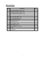
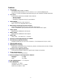
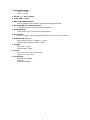
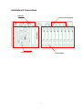
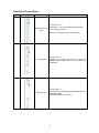
Digital Video Switcher
SE-900
INSTRUCTION MANUAL
(Preliminary)
www.datavideo-tek.com
Table of Contents
Warnings and Precautions ………………………………………………………………………
2
What's in the Box…………………………………………………………………………….……
3
Introduction………………………………………………………………….……………………
4
Features………………………………………………………………….…………………………
5
Installation & Connections …..…………………………………………………………….…….
7
Control Panel …..………………………………………………………………………………….
12
Install Video Interface cards ……………………………………………………………….…….
14
LCD Menu and Setting …………………………………………………………………….…….
16
Control Panel Operation………………………………………………………………………….
23
Multi-Camera Chroma-Key setup……………………………………………………………….
24
Transition Effects ………………………………………………………………………………….
27
Specification…………………………………………………………………………………………
28
Service & Support……………………………………………………………………………………
29
1
Warnings and Precautions
1. Read all of these warnings and save them for later reference.
2. Follow all warnings and instructions marked on this unit.
3. Unplug this unit from the wall outlet before cleaning. Do not use liquid or aerosol cleaners. Use a
damp cloth for cleaning.
4. Do not use this unit in or near water.
5. Do not place this unit on an unstable cart, stand, or table. The unit may fall, causing serious
damage.
6. Slots and openings on the cabinet top, back, and bottom are provided for ventilation. To ensure
safe and reliable operation of this unit, and to protect it from overheati ng, do not block or cover
these openings. Do not place this unit on a bed, sofa, rug, or similar surface, as the ventilation
openings on the bottom of the cabinet will be blocked. This unit should never be placed near or
over a heat register or radiator. This unit should not be placed in a built-in installation unless proper
ventilation is provided.
7. This product should only be operated from the type of power source indicated on the marking label
of the AC adapter. If you are not sure of the type of power available, consult your Datavideo dealer
or your local power company.
8. Do not allow anything to rest on the power cord. Do not locate this unit where the power cord will be
walked on, rolled over, or otherwise stressed.
9. If an extension cord must be used with this unit, make sure that the total of the ampere ratings on
the products plugged into the extension cord do not exceed the extension cord’s rating.
10. Make sure that the total amperes of all the units that are plugged into a single wall outlet do not
exceed 15 amperes.
11. Never push objects of any kind into this unit through the cabinet ventilation slots, as they may touch
dangerous voltage points or short out parts that could result in risk of fire or electric shock. Never
spill liquid of any kind onto or into this unit.
12. Except as specifically explained elsewhere in this manual, do not attempt to service this product
yourself. Opening or removing covers that are marked “Do Not Remove” may expose you to
dangerous voltage points or other risks, and will void your warranty. Refer all service issues to
qualified service personnel.
13. Unplug this product from the wall outlet and refer to qualified service personnel under the following
conditions:
a. When the power cord is damaged or frayed;
b. When liquid has spilled into the unit;
c. When the product has been e xposed to rain or water;
d. When the product does not operate normally under normal operating conditions. Adjust
only those controls that are covered by the operating instructions in this manual; improper
adjustment of other controls may result in damage to the unit and may often require
extensive work by a qualified technician to restore the unit to normal operation;
e. When the product has been dropped or t he cabinet has been damaged;
f. When the product exhibits a distinct change in performance, indicating a need for service.
2
What’s in the box?
Items
Description
Q’ty
1
SE-900 Main system and Control Panel
1
2
D-sub 9pin (M) to 9pin (F) cable L:1.2M
1
3
D-sub 9pin (M) to 9pin (M) cable L:1.2M
1
4
D-sub 15pin (M) to 15pin (F) cable L:1.2M
2
5
IEEE1394 6-6pin cable L:1.8M
1
6
YUV cable 4*BNC*4BNC L:3M
1
7
BNC to BNC c able L:1.2M
6
8
S-Video cable: 1.2M
1
9
2R to 2R cable L: 5 feet
1
10
Power supply 12V/1.2A
1
11
Switching Adaptor DC 12V/10A
1
12
AC cord
2
13
User’s Manual
1
3
Introduction
Datavideo SE-900 is an 8 inputs channel digital video switcher, featuring multi-format
inputs for each channel (choice of SDI, DV (DV25), Component YUV, S-video (Y/C),
Composite video and VGA) and an SDI Overlay port that will allow you to use your PC as
a character generator and/or graphics source. Equip with a 19” user friendly control panel
to connect with the Main unit thru RS-232 port for remote play back preset transitions and
effects instantly.
8 channels input TBC with YUV 4:2:2 frame synchronizers assures stable and high
quality video from virtually any source. Built in high quality Datavideo format converters
provide simultaneous analog and digital audio and video outputs.
A built in R.G.B. Color Processor and a Color Corrector for each input video, with settings
that are saved, allow you to fine tune your video. Programmable digital effects include
A/B Rolls, A/B Dissolves, Chroma-Keying, Mosaic, Picture in Picture, Strobe, Fades, and
Wipes. Digital audio delay interface for perfect lip-sync adjustment of Audio follow video
switching
4
Features
l
Video Formats
SDI (Support SMPTE 259M-C 270Mbps)
DV interface by DV25 format at Y.U.V. 4:1:1 NTSC or Y.U.V. 4:2:0 PAL 25Mbps bit rate
Analog Y.U.V. Video (Sony Betacam standard) Analog Y/C and Composite at CCIR601 NTSC/PAL
l
Video Inputs
8 input channels with three selectable video modules:
-. SDI input Module
-. DV input Module
-. Composite, Component & S(Y/C) input Module
l
Video Output
5-CH simultaneously video outputs of
SDI x 2, DV, YUV, Composite and S (Y/C)
l
Multi-image monitoring & Preview Output
Multi-image monitoring output for 8-CH video inputs source
Press on “PREVIEW” key to preview the next source effect on PST output.
l
Audio Inputs
Balanced and Unbalanced Audio Inputs
l
Audio Output
Balanced and Unbalanced Audio outputs
l
Audio Sync
Delay Time: - 16 Frames To + 1 Frames
l
8-CH 4:2:2 Frame Synchronizer at 13.5MHz
l
Chroma-Keyer (Optional Module)
Supports Chroma-key for up to four Cameras vs. four backgrounds in Sync. mode
l
Optional DSK interface
l
Digital Effects including
A/B Dissolve, PIP, Border lines, Chroma Key, Mosaic, Art Paint and more than 15 Wipe
effects With 6 Transition Speeds
l
Position Control With Mosaic Effect
Full Screen PIP Position Control by Joystick with 3 Mosaic size options
l
Instant Playback Keys:
F01 to F10, 10 Pre-program Keys
l Color Processing for each Input Video Channel
Brightness
+/-30%
Contrast
+/- 6dB
Color
+3/-10dB
l R.G.B. White Balance: +/- 10 Degrees
l Video Bandwidth
Component > 5.2 MHz
Composite and S (Y/C) > 5.0MHz
Audio 20 to 20 KHz +/-2dB
5
l Signal/Noise Ratio:
Video > 50 dB
Audio > 75 dB
l DG, DP +/- 3%, 3 degree
l Audio THD < 0.1%
l SDI CG Overlay Interface
SDI CG overlay in/out interface supports Blackmagic SDI cards
l RS-232 & RS-422 remote interface
For Remote Control Panel and Software Updating
l Tally Interface
Two D-SUB 15-pin connector for 8 tally outputs
l GPI Control
Remote Trigger Control Pre-program Effects from F01 to F10 in Sequence
l Dimension W x D x H
Rack system: 431mm * 438mm * 176mm
Control Panel: 431mm*314mm*92mm
l Weight:
Main unit: 11.4 Kg
Control Panel: 2.6Kg
l Power:
Input: AC 90 to 240V auto-sensing
Output: DC 12V/ 120W
l Accessories
AC/DC Power Adaptor
Cable set
Instruction Manual
6
Installation & Connections
Audio I/O
Control and Tally signal
Output interface
Input interface
7
Rear Panel Connections:
Item
1
Image
Part name
Analog Video Input
Card
Function Description
For Input slot 1~ 8.
Supports CV、YUV and S-VIDEO inputs terminal
1x CV monitoring output
Refer to menu “Video input format selecting”
2
DV Input Card
For Input slot 1~ 8
Supports DV Firewire input with DV signal deembedded audio output thru mini XLR connector for
Audio Mixer
SDI Input Card
For Input slot 1~ 8
SDI Video input card (Supports SMPTE259M without
Embedded Audio)
CV encode output for monitoring
3
8
4
SDI Input Card
(With Audio Deembedded output)
For Input slot 1~ 8
SDI Video input with de-embedded Audio output thru
Mini XLR connector
CV encode output for monitoring
5
CHROMA Key
Card
For slot 9
Dual Channel Chroma Key card
Preview Output
Card
For slot 11
Preview Output card, supports:
-. Multi-Image Preview output YUV or CV x 1
-. PGM output YUV x 1 or CV x 2
-. PST Output CV x 1
6
9
7
SDI CG Overlay
Card
For slot 12
CG Overlay card, supports:
- SDI CG Overlay input x 1 (From PC)
- SDI CG Overlay Output x 1 (To PC)
- SDI CG Output x 2
SDI PGM Output
Card
For slot 13
SDI PGM Outputs, support:
SDI PGM Output x 2
Gen-Lock BB output x 1
8
9
PGM Output Card
For Slot 14
Supports:
Y/C (S-Video) Output x 1
YUV output x 1
CV output x 1
DV output x 1
10
10
Remote Cont rol
Card
For slot 15
Supports:
GPI input x 1
RS-232 interface x 1
RS-422 interface x 1
11
Audio Input
Audio Input interface, supports:
Unbalance Audio input RCA x 2
Balance audio input XLR x 2
12
Audio Output
Audio Output interface, supports:
Unbalance Audio output RCA x 2
Balance audio output XLR x 2
11
Control Panel
Function and
Transition Effect
Joystick
Menu and Control
GPI
control
PRESET and SPD
Main/Sub Source
T-BAR
12
Control Panel:
Item
Image
Part name
Function Description
1
LCD Display
LCD Display for SE-900 system configuration and
setting
2
Menu and control
button
SE-900 Functions configuration and setting
3
T-BAR
Take bar for manual effects transition
4
Joystick
Adjust windows position for PIP
For RGB color correction
5
GPI Control and
Take-Key
Use GPI to trigger the function effect in sequence
Take-key for Auto-take the effect by preset speed
6
Video Source
Button
(Main/ SUB)
Selection of Main and Sub Video source
7
Function keys
10 function keys for presetting effects
8
SPEED Button
Selectable of 6 different speed for transition effect
9
Transition Buttons
15 effect keys
10
Effect Button
Selection of Effect functions:
PIP、CK(Chroma-Key)、LOGO、B/W,
STRB(Strobe)、BDR(Border) and Col or
13
Install video interface card
1.
Video Input card:
1-1. Install a video input card (SDI, DV, YUV/CV or VGA): Turn system power off,
install the card to one of the slot 1~ 8 as below
14
2.
Install a video output card
2-1 There are certain slot for certain function of video output cards, See the
printing
from rear panel to install video output cards accordingly.
2-2 Power on SE-900 and check from PGM、PVW output to ensure the installation
is correct.
15
System configuration
Press on the “SETTING” button for system configuration, turn the ADJUST Knob to select
an item and press down on the Knob to confirm the setting.
LCD Menu and Setting
1. CHROMA-KEY
Supports Green-Key, Blue-Key and Luma-key
Press on the “ADJUST” button to pop up the menu
as shown below, turn the “ADJUST” button and
select item 1 for Chroma-Key setting. There are two
pages of parameters (items 1-19) for Chroma Key
setting
1
2
3
4
5
6
7
8
9
10
11
CHROMA KEY NO.
CAM SOURCE
BKG SOURCE
KEY MODE
GREEN/BLUE Offset
LEVEL
DENSITY
DARK
BRIGHTNESS
SPILL
DARK DENSITY
TRANSPARENT LUMA
NEXT PAGE
1~ 4
1~ 8
1~ 8
GREEN, BLUE LUMA
-60~ +60
0~ 100
0~ 64
0~ 64
0~ 64
-32~ 64
0~ 64
0~ 100
1
2
3
4
5
6
7
8
9
10
11
12
CHROMA KEY
VIDEO IN
VIDEO OUT
LOGO (LUMA KEY)
CG INPUT
AUDIO DELAY
MULTI. IMAGE
EXT. GENLOCK
SYSTEM
CONTROLLER
STORE & RECALL
UPDATE FIRMWARE
ESCAPE
Chroma-Key adjustments:
- Select Chroma-key No.: To access the stored parameter
There are 4 sets (1~4) of memory to store different setting of Chroma-key
parameters, turn the knob to select a number of parameter set
- CAM. Source: Select the Foreground video input
There are 8 video inputs channel on SE-900, select any one of the 8 input as
Chroma-Key foreground. SE-900 supports simultaneous switching of foreground
and background video. Input CH1-4 is recommended as foreground input video.
16
- BKG. Source: Select the Background video input
Same as above foreground video setting, CH5-8 is recommended as background
video input.
- Key Mode: Green-Key/Blue-Key/Luma-key: Select the Key color Green/Blue or Luma
- Green/Blue Offset: To compensate the Camera’s white balance
- Level: Adjust key color level
- Density: Adjust the density of key object
- Dark: Adjust the shadow of object
0〜64, smaller number has less shadow effect, bigger number has more effect
- Bright: adjust the brightness of the object。
0〜64, smaller number has less brightness effect, bigger number has more effect
- Spill: To remove the reflecting key-color (green or blue) from object
–32〜64, smaller number has more green, bigger number has more red
- Dark Density: Adjust the density of shadow
0〜64,smaller number has less density, bigger number has higher density
- Transparent Luma: Adjust the transparent of Luma-Key
0 〜 100, smaller number has less transparent, bigger number has more
transparent
Next Page
- Shrink Left: Eliminate left edge of key object
0〜6 bigger number will eliminate more edge
- Shrink Right: Eliminate right edge of key object
0〜6 bigger number will eliminate more edge
- Matte Windows adjustment:
Window X Left:0〜720
Window X Right:0〜720
Window Y Top: 0〜576
Window Y Bottom:0〜576
- FG Brightness: Adjust brightness for Foreground vide
– 99〜 99, Smaller number will be darker, bigger number will be brighter
- FG Contrast:Adjust contrast for Foreground video
– 99〜 99, Smaller number will be softer, bigger number will be sharper
- FG Saturation: Adjust color Saturation for Foreground video
17
– 99〜 99, Smaller number has less saturation, bigger number has more saturation
- Pre. Page: Back to Previous page
- ESCAPE: Back to Main menu.
*. Some special features on Luma Key adjustment
- Dark Level:Adjust the black background level
- Dark Grad:Adjust density of black background and
level of black transparency and soft edge.
- Bright Level:Adjust the white level。
- Bright Grad:Adjust density of white background and
KEY MODE
(LUMA)
4
DARK LEVEL
0~100
5
DARK GRAD
0~100
6
BRIGHT LEVEL
0~100
7
BRIGHT GRAD
0~100
2. VIDEO IN:
An installed SDI and DV input Card will be autodetected and configured by system, however if the
installed video input card is an analog video input
card, it is required to select a correct input channel
of YUV, CV or Y/C from the LCD menu as below:
Select a correct video input
format of CV, S-VIDEO or
YUV if using an analog
video input card
LCD Menu and Setting
1
CHROMA KEY
2
3
4
5
VIDEO IN
VIDEO OUT
LOGO (LUMA KEY)
CG INPUT
6
7
8
9
AUDIO DELAY
MULTI. IMAGE
EXT. GENLOCK
SYSTEM
10
11
12
CONTROLLER
STORE & RECALL
UPDATE FIRMWARE
ESCAPE
Select Video Input Channel (1-8)
.
1
3
5
7
1
2
3
4
5
6
7
VIDEO_IN CH.
INPUT TYPE
BRIGHTNESS
CONTRAST
SATURATION
GBR CORRECTION
AGC
7.5 IRE
ALIAS
ESCAPE
1~ 8
CV, YUV, S-VIDEO, DV,SDI
-99~ +99
-99~ +99
-99~ +99
JOYSTICK CONTROL
ON, OFF
0, 7.5(NTSC)
CAM1…
18
2
4
6
Video input source calibration:
3.1.1- BRIGHTNESS adjustment: default at 0 adjustment range from - 99 to + 99
3.1.2- CONTRAST: default at 0 adjustment range from - 99 to + 99
3.1.3- SATURATIO: default at 0 adjustment range from - 99 to + 99
3.1.4- GBR CORRECTION: GBR correction by system Joystick as below:
Press on this
button to enable
GBR correction
3.1.5- AGC: Automatic Gain Control
3.1.6- 0/7.5 IRE: For NTSC video blanking setup
3.1.7- ALIAS: Assign name for input Camera, such as CAM1…
3. VIDEO OUT:
LCD Menu and Setting
-. Select the DV output mode and blanking setup for
analog video output from the LCD menu as below.
-. Set the SDI Gen-Lock output as BB or CV
VIDEO OUT SETTING
ANALOG & DV OUT
1
DV OUT MODE
1~4(default=1)
2
V. OUT – IRE
0 , 7.5 (NTSC ONLY)
SDI OUT
1
BLACK_BURST/ CV
BB, CV
ESCAPE
1
2
3
4
5
6
7
8
9
10
11
12
CHROMA KEY
VIDEO IN
VIDEO OUT
LOGO (LUMA KEY)
CG INPUT
AUDIO DELAY
MULTI. IMAGE
EXT. GENLOCK
SYSTEM
CONTROLLER
STORE & RECALL
UPDATE FIRMWARE
ESCAPE
4. LOGO (LUMA-KEY):
LCD Menu and Setting
(Function not available; to be upgraded by new firmware)
1
2
3
CHROMA KEY
VIDEO IN
VIDEO OUT
4
5
6
7
LOGO (LUMA KEY)
CG INPUT
AUDIO DELAY
MULTI. IMAGE
8
9
10
11
EXT. GENLOCK
SYSTEM
CONTROLLER
STORE & RECALL
12
UPDATE FIRMWARE
ESCAPE
LOGO LUMA KEY SETTING
1
2
3
4
SOURCE
KEY LEVEL MAX.
KEY LEVEL MIN
DARK GRAD
No,CH1~8,INTERNAL
0~255
0~255
0~100
5
6
7
LOGO POSITION X
LOGO POSITION Y
STORE LOGO DATA
ESCAPE
0~
0~
96x64 BMP file From SD card
19
5. CG INPUT:
Works with Datavideo CG-100 with Blackmagic Decklink
PCI cards (Decklink 2, Decklink Pro, Decklink SP and
Decklink Extreme…) for SDI CG overlay function.
CG CARD SETTING
1
MODE
EXTERNAL/INTERNAL
2
KEY LEVEL MAX
(INTERNAL)
0~255
3
KEY LEVEL MIN
(INTERNAL)
0~255
4
5
DARK GRAD
(INTERNAL)
VER. OFFSET OF SDI_IN
ESCAPE
0~100
0~32
6. AUDIO DELAY:
-. Adjust audio delay time by frame or mini-second
-. From 0 ~ 17 frames or
-. From 10 ms to 680 ms
-. Audio output gain adjustment from 0 ~ 60dB
-. Supports 1K/11K/22KHz tone output and
adjustable level 18 ~ -42dB for audio calibration
-. DV Audio output gain adjustment from +6 ~ -12dB
-. 0dB audio output calibration
AUDIO DELAY SETTING
1
AUDIO DELAY
2
DELAY TIME
3
TIME UNIT
4
AUDIO GAIN
5
TONE OUTPUT
6
TONE MODE
7
TONE LEVEL
8
DV OUTPUT GAIN
9
0dB OUT ADJ.
ESCAPE
OFF, ON
0~17 Frame or 0~700ms
Frame OR ms
0~ -60 dB
OFF, ON
MUTE/ 1K~
18~ - 42 dB
6~ -12 dB
1.5 ~ -1.5 dB
20
LCD Menu and Setting
1
CHROMA KEY
2
3
4
5
VIDEO IN
VIDEO OUT
LOGO (LUMA KEY)
CG INPUT
6
7
8
9
AUDIO DELAY
MULTI. IMAGE
EXT. GENLOCK
SYSTEM
10
11
12
CONTROLLER
STORE & RECALL
UPDATE FIRMWARE
ESCAPE
LCD Menu and Setting
1
2
3
4
5
6
7
8
9
10
11
12
CHROMA KEY
VIDEO IN
VIDEO OUT
LOGO (LUMA KEY)
CG INPUT
AUDIO DELAY
MULTI. IMAGE
EXT. GENLOCK
SYSTEM
CONTROLLER
STORE & RECALL
UPDATE FIRMWARE
ESCAPE
7. MULTI. IMAGE:
LCD Menu and Setting
-. Supports Multi-Image output from CV or YUV
-. Top/Bottom image position
-. Adjustable screen size 100%, 90% or 80%
-. Noise filter
MULTI. IMAGE SETTING
1
OUTPUT TYPE
2
IMAGE POSITION
3
SCREEN SIZE
4
NOISE FILTER
5
ESCAPE
YUV, CV,
TOP, BOTTOM
100% ,90% ,80%
BYPASS, LOW, MID, HIGH
1
2
3
4
5
6
7
8
9
10
11
12
CHROMA KEY
VIDEO IN
VIDEO OUT
LOGO (LUMA KEY)
CG INPUT
AUDIO DELAY
MULTI. IMAGE
EXT. GENLOCK
SYSTEM
CONTROLLER
STORE & RECALL
UPDATE FIRMWARE
ESCAPE
8. EXT. GENLOCK:
(Function not available; to be upgraded)
9. SYSTEM:
-
LCD Menu and Setting
System function setup
21
1
2
3
CHROMA KEY
VIDEO IN
VIDEO OUT
4
5
6
7
LOGO (LUMA KEY)
CG INPUT
AUDIO DELAY
MULTI. IMAGE
8
9
10
11
EXT. GENLOCK
SYSTEM
CONTROLLER
STORE & RECALL
12
UPDATE FIRMWARE
ESCAPE
LCD Menu and Setting
10. CONTROLLER:
-. LCD contras and backlight level control
-. RS-232 Remote mode setting
-. Switch light setting
CONTROLLER SETTING
1
LCD CONTRAST
2
LCD BACK LIGHT
3
REMOTE MODE
4
SWITCH COLOR
5
SWITCH BRIGHTNESS
ESCAPE
1~ 8 LEVEL
1~ 8 LEVEL
RS-232
SWAP, NO SWAP
1~ 4 LEVEL
1
2
CHROMA KEY
VIDEO IN
3
4
5
6
VIDEO OUT
LOGO (LUMA KEY)
CG INPUT
AUDIO DELAY
7
8
9
10
MULTI. IMAGE
EXT. GENLOCK
SYSTEM
CONTROLLER
11
12
STORE & RECALL
UPDATE FIRMWARE
ESCAPE
LCD Menu and Setting
11. STORE & RECAL L:
-
Function keys setting
10 sets of user’s setting and recall
Function key reset
STORE & RECALL
1
STORE FUNC. KEY
F1~ F10
2
RECALL FROM
USER 1~ 3
3
STORE TO
USER 1~ 3
4
RESET ALL
NO, YES
ESCAPE
1
2
3
CHROMA KEY
VIDEO IN
VIDEO OUT
4
5
6
7
LOGO (LUMA KEY)
CG INPUT
AUDIO DELAY
MULTI. IMAGE
8
9
10
11
EXT. GENLOCK
SYSTEM
CONTROLLER
STORE & RECALL
12
UPDATE FIRMWARE
ESCAPE
LCD Menu and Setting
11. FIRMWARE UPDATE:
-. System firmware update
UPDATE FIRMWARE
1
SELECT UPDATE MODE
NORMAL. DETAIL
ESCAPE
1
2
3
4
CHROMA KEY
VIDEO IN
VIDEO OUT
LOGO (LUMA KEY)
5
6
7
8
CG INPUT
AUDIO DELAY
MULTI. IMAGE
EXT. GENLOCK
9
10
11
12
SYSTEM
CONTROLLER
STORE & RECALL
UPDATE FIRMWARE
ESCAPE
22
CONTROL PANEL OPERATION
PIP, Mosaic and Paint effect
Chroma-key, CK w/sync and CG
Strobe, B/W effect and LOGO
Border, Border color and
Background color
PIP (Picture in Picture):
To enable the PIP preview function on SE-900
-. Set the PIP windows for output video
-. Press on PIP button to preview output on the windows
-. Use T-Bar to enable Program output
MOSAIC EFFECT:
- Enable Mosaic effect on the sub- source
- Press on POS Control button to enable Joystick control for Mosaic effect
Press to enable
position control for
Mosaic effect
- Push on T-BAR switch Mosaic effect to PGM output
- Press on “Mosaic” button for three different sizes of Mosaic effect
PAINT EFFECT:
- Enable “Paint” effect on the sub- source
- Push on T-BAR switch Paint effect to PGM output
- Press on “Paint” button for four different Paint effect
23
Setup example of Multi-Camera CHROMA-KEY operation in SYNC:
Equipments for Multi- Camera Chroma-Key Setup
-. 2 or more camera for FG source inputs
-. 2 or more BG video source inputs
Connection:
FG-2
FG-1
BG-1
Video in 1~ 4
Video in 5~ 8
SE-900
PGM OUT
Chroma Sync- 1
Chroma Sync- 2
Operating procedure:
1.
2.
3.
4.
Connecting FG video inputs to channel #1~ 4
Connecting BG video sources to channel #5~8
Press on CK button to activate Chroma key function
Check if “ CK SYNC” button is activated with RED light on
5. Push on T-Bar to switch FG from 1~ 4, BG will follow as below:
FG
BG
Channel# 1
Video in# 1
Video in# 5
Channel# 2
Video in# 2
Video in# 6
Channel# 3
Video in# 3
Video in# 7
Channel# 4
Video in# 4
Video in# 8
24
BG-2
CG (SDI CG OVERLAY)
- Connecting SDI Overlay In/Out from SE-900 to PC Decklink card SDI Out/In.
- Press on “CG” button to enable CG overlay
- Enable CG-100 software and run a VCG file
-. Click on the “Play” button for CG overlay output
STROBE: (Not available yet)
B/W (Black/White) Effect:
- Select the sub- source for B/W effect
- Press on “B/W” button to enable the effect
- Push on T-BAR switch B/W effect to PGM output
LOGO Insertion (Not available yet)
BDR (Border)
- Enable border for effect transition
- Press on “BDR” button for 3 different border
BDR CLR (Border color)
- Enable border color
- Supports 8 different colors
BGCL (Background color)
- Work with “BK” button
- Press on “BK” and push on “BKCL” button for different background colors
- Supports 8 different colors
25
Others Effect Keys
BG (Background)
- Press on “BG” button on the video sub-source line
- Push on T-Bar to switch PGM to background color output
FTB (FADE TO BLACK)
- Press on “FTB” button
- Press on T-Bar to fade out to black
FZ (Freeze)
- Press on “FX” button to freeze PGM output
- Press again to release
Speed Key Setting (Effect transition speed) (Not available yet)
-. Transition Speed setting
- Select from LCD MENU
- SPEED SETTING 1~ 5
-. Enable / Disable transition speed
- Press on “SPD” button
-. Select SPEED1~ 5
-. Press on TAKE key for Auto-take
Preset Memory (User setting) (Not Available yet)
-. Store or Re-call the user setting (refer to page 23 LCD menu)
26
Transition Effects:
1
9
Left High to Right Down
Left to Right
2
10
Right Down to Left High
Right to Left
3
11
Left Down to Right High
Bottom UP
4
12
Top to Bottom
5
Right High to Left Down
13
Middle extend U/D
6
Outside In
14
Inside Out
Squeeze
7
15
Middle extend U/D
Fade IN/OUT
8
Middle extend L/R
Remote Control Interface
-. RS-232 Remote: Proprietary Datavideo Protocols
-. RS-422 Remote: Sony Protocol
-. GPI Remote: Wired Remote Trigger Control as “Take key”
27
SPECIFICATION
Digital Video Input:
SDI(SMPTE 272M-C 270Mbps with Embedded Audio)
8-CH Video
inputs
Video Outputs
DV25, (25Mbps, Y.U.V. 4:1:1 NTSC or Y.U.V. 4:2:0 PAL)
Analog Video Input:
Y/C 和 Composite compliant to CCIR601 NTSC & PAL
Component Y.U.V Sony Betaca m Spec
VGA (Not available yet)
DV, YUV, Y/C & Composite, Optional SDI output
Bandwidth: > 5.0mHz
Video Spec
Preview
Differential of Gain(DG)<3%
Differential of Phase(DP)<3°
S/N: > 50 dB
Preview and Multi-Image output
Brightness: ±30%
Color correction Contrast: ±6dB
Hue: +3dB / -10dB
R.G.B & White Balance: ±10 Degrees
Audio Outputs
Audio Inputs
RCA & XLR (±12Vp-p)
RCA& XLR (Thru Audio Delay control, SDI/DV Audio Embedded)
Bandwidth: 20~20KHz ±2dB
Audio Spec
Distortion: < 0.1%
S/N: > 65 dB
Audio Delay
Delay control from +1 Frames to -16 Frames
Chroma-Key
4:2:2Dual graphic Processor Chroma-key Module (Optional item)
Video Effects
FTB, Wipes, Zoom, Fades, PIP, Mosaic, Paint, LOGO Insertion…
TALLY outputs
CG
Others
D-SUB 15PIN Interface x 2 for CH1-4 and CH5-8
SDI Text Overlay Interface, together with Datavideo CG-100 SDI CG overlay
Software and Blackmagic DeckLink SDI cards
Transition Speed setting, RS-232, RS-422, GPI Remote control…
Dimension and
Weight
CPU: 430mm (W) x 350mm (H) x 176mm (D);11.4Kgs
Control Panel:: 430mm(W) x 310mm (H) x 95mm(D); 2.6Kgs
Power
Input AC 100 ~ 240V Switching Adaptor, output DC 12V / 10A
28
Service and Support
It is our goal to make your products ownership a satisfying experience. Our supporting staff is
available to assist you in setting up and operating your system. Please refer to our web site
www.datavideo-tek.com for answers to common questions, support requests or contact your
local office below.
Datavideo Corporation (USA)
12300-U East Washington Blvd., Whittier, CA 90606 USA
Tel: +1 562 696 2324
[email protected]
www.datavideo.us
Datavideo Technologies Europe BV
Floridadreef 106, 3565 AM Utrecht, The Netherlands
Tel: +31 30 261 9656
[email protected]
www.datavideo.info
Datavideo UK Limited
Unit 2 Waterside Business Park, Hadfield, Glossop, Derbyshire SK13 1BE UK
Tel: +44 1457 851000
[email protected]
www.datavideo.info
Datavideo Technologies Co., Ltd.
10F, 176 Jian-Yi Rd, Chung Ho City, Taipei Hsien, Taiwan 235
Tel: +886 2 8227 2888
[email protected]
www.datavideo.com.tw
Datavideo Technologies China Co.
2F-D, 2 Lane 777, West Guangzhong Rd, Zhabei District, Shanghai, China
Tel: +86 21 5603 6599
[email protected]
www.datavideo.cn
Datavideo Technologies (S) PTE Ltd.
No. 22 Lorong 21A Geylang, #09-02 Prosper Industrial Building, Singapore 388431
Tel: +65 6749 6866
[email protected]
www.datavideo.sg
Datavideo Hong Kong Limited
G/F., 26 Cross Lane, Wanchai, HK
Tel: +852 2833 1981
[email protected]
All the trademark s are the properties of their respective owners.
Datavideo Technologies Co., Ltd. All rights reserved 2018.
29
www.datavideohk.com