1
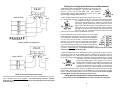
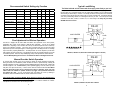
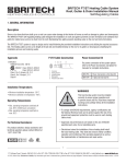
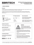
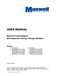
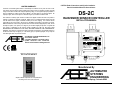
LIMITED WARRANTY
The DS-2C is warranted against defects in workmanship and materials for two years from date of sale.
This warranty does not apply to damage resulting from accident, misuse, or alteration nor where connected
voltage is more than 5% above the configured operating voltage, nor to equipment improperly installed or
wired or maintained in violation of this Owner’s Manual. No other written or oral warranty applies. No
employee, agent, dealer or other person is authorized to give any warranties on behalf of ASE.
Units returned for warranty repair cannot be modified from shipped condition and leads must protrude a
minimum of 6 inches from the base conduit hub. Repair costs of a modified unit will be quoted as the unit
must be returned to the original, unmodified condition prior to return shipping. The customer shall be
responsible for all costs incurred in the removal or reinstallation and shipping of the product for repairs.
Within the limitations of this warranty, inoperative units should be returned, freight prepaid, to ASE, and we
will repair or replace, at our option, at no charge to you with return freight paid by ASE. It is agreed that
such repair or replacement is the exclusive remedy available from ASE and that ASE IS NOT
RESPONSIBLE FOR DAMAGES OF ANY KIND, INCLUDING INCIDENTAL AND CONSEQUENTIAL
DAMAGE. Some states do not allow the exclusion or limitation of incidental or consequential damages so
the above exclusion may not apply to you. The warranty gives you specific legal rights, and you may also
have other rights which vary from state to state.
AUTOMATED SYSTEMS ENGINEERING, INC.
2519 E SAINT VRAIN ST
COLORADO SPRINGS, COLORADO 80909
PHONE: 719-599-7477 FAX: 719-599-7482
Visit us on the Internet at: www.goase.com
CAUTION: Read all instructions carefully before installation.
Save this Installation Manual for future reference.
DS-2C
RAIN/SNOW SENSOR CONTROLLER
INSTALLATION MANUAL
AUTOMATED
SYSTEMS
ENGINEERING
ENCLOSURE TYPE 3R
DS−2C
INDICATOR
OFF
POWER
ACTIVATED
RAIN/SNOW SENSOR CONTROLLER
DANGER
CM
C
CONFORMS TO UL STD 508
CERTIFIED TO CAN/CSA STD C22.2 NO. 14
INPUT
100−277V AC 0.15 A 50/60 Hz
CONTROL
30 A 277V AC, 20 A 28V DC
CM
C
LI S T E D
US
L I ST E D
US
Intertek
3175102
CONTROL SWITCH
MANUAL ON
AUTOMATIC
STANDBY/RESET
WARNING: THIS UNIT MAY BE SUPPLIED BY MORE THAN ONE BREAKER
AVERTISSEMENT: IL PEUT Y AVOIR UN CIRCUIT SECONDAIRE SOUS TENSION
Intertek
Need Indoor Monitoring & Control?
Take a Look at the ASE CDP-2
Manufactured By
Simple Installation & Operation at a Competitive Price
Visit www.goase.com for more information
AUTOMATED
SYSTEMS
ENGINEERING
2519 East Saint Vrain St Colorado Springs, Colorado 80909
General Safety Instructions
1. THIS UNIT SHOULD BE INSTALLED, OPENED, AND REPAIRED BY QUALIFIED PERSONNEL
ONLY!
CETTE UNITÉ DEVRAIT ÊTRE INSTALLÉE, OUVERTE, ET RÉPARÉE PAR LE PERSONNEL
QUALIFIÉ SEULEMENT!
2. To avoid shock hazard do not open the front cover with power connected to the DS-2C or any controlled
equipment.
Pour éviter la décharge électrique déconnectez toute la puissance avant d'ouvrir la couverture du DS2C.
Selecting a Mounting Location for the DS-2C
The interleaved grid on the top of the DS-2C is the precipitation or “moisture" sensor. The brass cylinder protruding from
the bottom of the enclosure is the temperature sensor. For reliable rain and snow detection the unit must be mounted in
a location that exposes the moisture sensor to a clear view of the sky. The unit should not be mounted directly under
eaves or overhangs. It should not be mounted so close to the ground that it may become buried in snow. For proper
temperature detection the DS-2C must be mounted outdoors, away from furnace vents, dryer vents, and other sources
of heat. Note that, when powered, the DS-2C moisture grid will always remain hot. This is normal. This allows the sensor
to continuously melt snow and evaporate both rain and snow from the grid.
The DS-2C can be mounted by screwing the base conduit hub onto an appropriate size free-standing conduit or by
using the mounting holes in each corner of the enclosure.
DO NOT DRILL HOLES THROUGH THE ENCLOSURE FOR MOUNTING!
NE FONT PAS LES TROUS DE FORET PAR LA BOÎTE POUR LE SUPPORT!
This can allow water into the enclosure causing a potential shock hazard. It is recommended that a weatherproof
junction box be mounted below the DS-2C for termination of the power and load pigtails to the building wiring.
Use Care When Replacing the Front Cover. Do Not Pinch the Gasket or Overtighten the Screws.
CONTROL/MONITOR JACK
CONFIGURATION SWITCH
GRID JACK
SWITCH JACK
TEMPERATURE ADJUST
DELAY OFF ADJUST
SENSITIVITY ADJUST
External Control/Monitor Operation
The DS-2C provides external control/monitor capability. Shielded
cable rated 300V or higher can be connected to TB2 to access
this feature. Connecting Black (4) to White (1) will activate the
“Manual On” function. Connecting Green (5) to White (1) will
activate the “Standby/Reset” function. See the “Manual Override
Switch Function” for a description of these modes. The
Red/Orange (2/3) leads are connected to an internal low power
monitor relay. This relay, rated at 24 VAC/VDC at 400 ma, will close with the load relay and can be used to
externally monitor activation of the sensor. This terminal block is also the connection point for installing a
CDP-2 interface cable.
Pin
1
2
3
4
5
Color
White
Red
Orange
Black
Green
Function
GND/Common
Deice On Mon A
Deice On Mon B
Manual On
Standby/Reset
Power & Activation Indicator
A green lamp shines through a lens on the cover of the DS-2C to indicate operational status. If this lamp is
OFF the DS-2C is not receiving power. If this lamp is steady ON the DS-2C is powered but not triggered.
If this lamp is FLASHING the DS-2C is powered on and triggered, the main relay is closed, and attached
equipment should be activated. Note that, even though snow or rain may have stopped, the DS-2C
indicator will continue to flash during the Delay-Off drying cycle.
Moisture Grid Maintenance & Replacement
It is recommended that the DS-2C be powered down and the grid wiped clean with clear water at least
once every 4 months. Heavy deposits may be removed using a non-metallic scouring pad (Scotch-BriteTM
or equivalent.) However, after a number of years, the corrosive elements left behind when water is
evaporated out of the moisture grid will eventually damage the grid rings. The moisture grid can be easily
replaced by ordering and installing an MG-5 “Moisture Grid Assembly” and following the procedure below:
THIS PROCEDURE SHOULD ONLY BE PERFORMED BY QUALIFIED PERSONNEL!
CE PROCÉDÉ DEVRAIT SEULEMENT ÊTRE EXÉCUTÉ PAR LE PERSONNEL QUALIFIÉ!
Open all power and load breakers connected to the DS-2C. Open the front cover and remove the cable
connector from the Grid Jack. While holding the reducing bushing, unscrew and remove the old moisture
grid. Install the supplied thread sealing tape, place the new grid through the sealing ring, into the top hole,
and screw the assembly into the reducing bushing. Tighten the grid hand tight plus ¼ turn. Reconnect the
new cable to the Grid Jack. Confirm that the four connector pins are properly aligned with the jack. Close
the front cover, confirming that the front cover gasket is properly sealed. Reapply power.
Use Care When Replacing the Front Cover. Do Not Pinch the Gasket or Overtighten the Screws.
Preseason Snow Detection Testing
LOAD
INPUT POWER
ALWAYS FOLLOW LOCAL AND NATIONAL ELECTRICAL CODES
TOUJOURS SUIVRE LES CODES ÉLECTRIQUES LOCAUX ET NATIONAUX
2
It is always a good idea to test the operation of the DS-2C prior to the winter season. Procure some clean
water and, if the outdoor temperature is above the trigger point, a can of spray component cooler (Radio
Shack Part #64-4321 or equivalent.) Clean the moisture grid following the procedure outlined above and
allow it to dry. Apply power to the DS-2C, drip some of the water onto the moisture grid, then spray the
temperature sensor protruding from the base of the enclosure with the component cooler. Once the
temperature sensor has reached the trigger point with water still present on the grid the DS-2C will activate.
The user should hear the internal control relay close and see the green lamp blink. Proper operation has
been confirmed. Allow the grid to dry completely. To clear the Delay-Off timer place the override switch
into “Standby/Reset”, and then back to the “Automatic” position.
7
Setting the Configuration Switches and Adjustments
DS−2C
POWER SUPPLY
YELLOW
YELLOW
BROWN
LOAD CENTER
BLUE
CB2
CB1
LOAD
The following paragraphs and table outline the operating modes for the DS-2C and
explain the functions of the adjustments. Trigger temp (TT) is adjustable from
34°F-44°F (1°C-6°C) using the TRIG TEMP control. When ambient air
temperature (AT) is below this setting precipitation is assumed to be snow. When
above this setting, precipitation is assumed to be rain.
The DEL configuration switch activates the Delay-Off drying cycle timer on the DS2C. The timer allows the DS-2C to continue to operate and dry the heated surface through evaporation
once precipitation has stopped. The drying cycle reduces the chance of
moisture left behind refreezing into ice. This timer is restarted by each
sensor trigger. Therefore, the DS-2C will continue to operate as long as it is
triggered, then for the Delay-Off period once the trigger clears. All "sensor"
modes (DEL off) provide a 2 minute Delay-Off time. When in "controller"
mode (DEL on) the Long Delay (LD) configuration switch determines the time
span of the drying cycle. The Delay-Off time can be adjusted from 30-90
minutes (LD Off) or 2-6 hours (LD On) using the DELAY OFF control.
The Low Temperature Cutoff (LTC) option is typically used on snow melting
systems with limited output capacity where melting cannot be maintained at
very low temperature. If selected, the snow sensor will clear a trigger below
5°F (-15°C) even if snow is still falling. It will resume normal operation
above 9°F (-13°C). However, the sensor will remember if it was triggered
before the drop below 5°F or if snow was detected during the cold period. If
so, the sensor will execute one Delay-Off cycle when the temperature rises
above 9°F in order to melt any snow left behind during the cold period. This
is referred to as RECOVER mode. Care should be exercised in using this mode as the potential
exists for ice to be formed on the melting surface.
NEUTRAL BUS BAR
120VAC In, 240VAC Load, Separate Feed
DS−2C
POWER SUPPLY
BROWN
LOAD CENTER
YELLOW
YELLOW
LOAD
CB
BLUE
240VAC In, Dry Contact for Boiler/Circulation Pump
These are just some of the possible wiring schemes that can be used to connect the DS-2C to your load for
control. Remember, these are only suggestions. You should always consult a qualified
electrician or inspector to assure conformance with applicable local and national
electrical codes!
The DS-2C precipitation sensor is very sensitive and can detect a single snow flake or rain drop. However,
if the DS-2C is mounted in an area susceptible to high winds, overhanging trees, or blowing ground snow,
nuisance triggering may occur. While proper placement is the best remedy, the SENSITIVITY control can
also be used to reduce nuisance triggering. An internal timer checks the precipitation sensor for moisture
and compares cleared time with triggered time. The highest sensitivity
setting (toward MORE) triggers on first detection. As the control is
adjusted clockwise precipitation must be detected for a longer period to be
considered valid. The lowest sensitivity setting (toward LESS) requires
120 seconds of detection before the unit triggers. If a trace amount of
snow blows onto the grid from a drift or overhang it will likely be melted
and evaporated in less than a minute. Similarly, a very light snowfall may also clear quickly from the grid.
If these conditions should be ignored by the sensor the SENSITIVITY control can be adjusted as required.
However, to prevent non-triggering during a true event, it is recommended that the user start at highest
sensitivity (MORE), then adjust while monitoring operation over time.
THE UNIT MUST BE IN STANDBY/RESET TO CHANGE CONFIGURATION SWITCHES
L'appareil doit être en mode STANDBY/RESET pour modifier commutateurs de configuration
3
6
Recommended Switch Settings by Function
Trigger
LD Off
LD On
LTC
DEL
RAIN SNOW
TT>AT
2 Min
2 Min
OFF
OFF
OFF
ON
TT>AT>5°F
2 Min
2 Min
ON
OFF
OFF
ON
TT>AT
30-90 Min
2-6 Hr
OFF
ON
OFF
ON
TT>AT>5°F
30-90 Min
2-6 Hr
ON
ON
OFF
ON
Precipitation sensor
Not Used
2 Min
2 Min
X
OFF
ON
ON
Precipitation controller
Not Used
30-90 Min
2-6 Hr
X
ON
ON
ON
Rain sensor
AT>TT
2 Min
2 Min
X
OFF
ON
OFF
Rain controller
AT>TT
30-90 Min
2-6 Hr
X
ON
ON
OFF
LT thermostat w\o LTC
TT>AT
2 Min
2 Min
OFF
X
OFF
OFF
Snow sensor w\o LTC
Snow sensor w\LTC
Snow controller w\o LTC
Snow controller w\LTC
LT thermostat w\LTC
TT>AT>5°F
2 Min
2 Min
ON
X
OFF
OFF
X = Do Not Care
Fine Adjustment for Efficient Operation
The DS-2C is shipped with the TRIG TEMP and DELAY OFF adjustments in the center position,
representing 39°F (3.9°C) and 60 minutes of Delay-Off time respectively. It is also set for highest
SENSITIVITY. Depending on local conditions the user may find that fine adjustment of the controls may
provide more satisfactory operation. If the sensor does not trigger during very wet snows the trigger
temperature may need to be adjusted higher. Constant triggers from snow falling from trees or overhangs
may be reduced by adjusting SENSITIVITY. The Delay-Off time can also be adjusted to provide clean
melt-off without excessive running time. Fine adjustment can both save operating expense and provide
more reliable operation. However, to keep reliability high, always make adjustments in small increments.
Use Care When Replacing the Front Cover. Do Not Pinch the Gasket or Overtighten the Screws.
The Yellow load leads are N.O. contacts and do not supply power directly to your load
The relay inside the DS-2C acts as a switch. While not as convenient as directly supplying power for the
load this allows you to operate the DS-2C from one voltage while controlling a load of a different voltage
without adding an external relay or contactor. For example, the DS-2C can be powered from 120VAC but
can directly control a 24VAC signal for a boiler system or 277VAC for heating wire. The following diagrams
show some possible wiring schemes for connecting the DS-2C to your load. Your load may be a direct
connection to heat cable, a heater, a contactor coil, or a control voltage. For clarity the green safety
GROUND leads are not shown.
DS−2C
POWER SUPPLY
BLUE
If the override switch is placed in MANUAL ON for less than 2 seconds, then switched back to
AUTOMATIC the controller will execute one Delay-Off cycle. This can be used to clear a frost, hail, or
drifted snow buildup without the danger of leaving the system in a continuous “Manual On” condition.
“Standby/Reset” can still be used to clear this Delay-Off cycle.
4
LOAD
SWITCHED 120VAC
NEUTRAL
NEUTRAL BUS BAR
120VAC In, 120VAC Load, Heat Cable or Similar (Also Applies To 277VAC)
DS−2C
Manual Override Switch Operation
POWER SUPPLY
BROWN
LOAD CENTER
BLUE
YELLOW
YELLOW
LOAD
SWITCHED 240VAC
CB
An override switch mounted on the side is provided for testing and special operational requirements.
Placing the switch in the AUTOMATIC position will allow the sensor to operate normally, activating the
controlled equipment as needed. Placing the switch in MANUAL ON will close the load relay, activating the
controlled equipment. The “STANDBY/RESET” position prohibits triggering of the unit, clears any active
delay timer, and opens the load relay. In order to reduce excessive runtime for the heater the “Manual
On” mode will remain in effect for up to 40 hours, then return to “Automatic” mode, even if the
switch is still in the “Manual On” position. However, any trigger of the system will restart the 40
hour “Manual On” timer. You may put the DS-2C back into “Manual On” mode by switching to
AUTOMATIC, then back to MANUAL ON. This will also restart the 40 hour timer.
YELLOW
YELLOW
BROWN
LOAD CENTER
CB
Function
Typical Load Wiring
240VAC In, 240VAC Load, Heat Cable or Similar
5