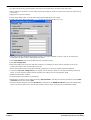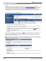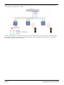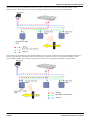
1
IP Office
IP DECT Installation
15-601085 Issue 04f - (11 June 2009)
© 2009 AVAYA All Rights Reserved.
Notice
While reasonable efforts were made to ensure that the information in this document was complete and accurate at the time of
printing, Avaya Inc. can assume no liability for any errors. Changes and corrections to the information in this document may be
incorporated in future releases.
Documentation Disclaimer
Avaya Inc. is not responsible for any modifications, additions, or deletions to the original published version of this
documentation unless such modifications, additions, or deletions were performed by Avaya.
Link Disclaimer
Avaya Inc. is not responsible for the contents or reliability of any linked Web sites referenced elsewhere within this
Documentation, and Avaya does not necessarily endorse the products, services, or information described or offered within
them. We cannot guarantee that these links will work all of the time and we have no control over the availability of the linked
pages.
License
USE OR INSTALLATION OF THE PRODUCT INDICATES THE END USER’S ACCEPTANCE OF THE TERMS SET FORTH
HEREIN AND THE GENERAL LICENSE TERMS AVAILABLE ON THE AVAYA WEBSITE AT
http://support.avaya.com/LicenseInfo/ (“GENERAL LICENSE TERMS”). IF YOU DO NOT WISH TO BE BOUND BY THESE
TERMS, YOU MUST RETURN THE PRODUCT(S) TO THE POINT OF PURCHASE WITHIN TEN (10) DAYS OF DELIVERY
FOR A REFUND OR CREDIT.
Avaya grants End User a license within the scope of the license types described below. The applicable number of licenses and
units of capacity for which the license is granted will be one (1), unless a different number of licenses or units of capacity is
specified in the Documentation or other materials available to End User. “Designated Processor” means a single stand-alone
computing device. “Server” means a Designated Processor that hosts a software application to be accessed by multiple users.
“Software” means the computer programs in object code, originally licensed by Avaya and ultimately utilized by End User,
whether as stand-alone Products or pre-installed on Hardware. “Hardware” means the standard hardware Products, originally
sold by Avaya and ultimately utilized by End User.
License Type(s): Designated System(s) License (DS).
End User may install and use each copy of the Software on only one Designated Processor, unless a different number of
Designated Processors is indicated in the Documentation or other materials available to End User. Avaya may require the
Designated Processor(s) to be identified by type, serial number, feature key, location or other specific designation, or to be
provided by End User to Avaya through electronic means established by Avaya specifically for this purpose.
Copyright
Except where expressly stated otherwise, the Product is protected by copyright and other laws respecting proprietary rights.
Unauthorized reproduction, transfer, and or use can be a criminal, as well as a civil, offense under the applicable law.
Third-Party Components
Certain software programs or portions thereof included in the Product may contain software distributed under third party
agreements (“Third Party Components”), which may contain terms that expand or limit rights to use certain portions of the
Product (“Third Party Terms”). Information identifying Third Party Components and the Third Party Terms that apply to them is
available on Avaya’s web site at: http://support.avaya.com/ThirdPartyLicense/
Avaya Fraud Intervention
If you suspect that you are being victimized by toll fraud and you need technical assistance or support, call Technical Service
Center Toll Fraud Intervention Hotline at +1-800-643-2353 for the United States and Canada. Suspected security
vulnerabilities with Avaya Products should be reported to Avaya by sending mail to: [email protected].
For additional support telephone numbers, see the Avaya Support web site (http://www.avaya.com/support).
Trademarks
Avaya and the Avaya logo are registered trademarks of Avaya Inc. in the United States of America and other jurisdictions.
Unless otherwise provided in this document, marks identified by “®,” “™” and “SM” are registered marks, trademarks and
service marks, respectively, of Avaya Inc. All other trademarks are the property of their respective owners.
Documentation information
For the most current versions of documentation, go to the Avaya Support web site (http://www.avaya.com/support) or the IP
Office Knowledge Base (http://marketingtools.avaya.com/knowledgebase/).
Avaya Support
Avaya provides a telephone number for you to use to report problems or to ask questions about your contact center. The
support telephone number is 1 800 628 2888 in the United States. For additional support telephone numbers, see the Avaya
Web site: http://www.avaya.com/support.
IP DECT Installation
IP Office
Page 2
15-601085 Issue 04f (11 June 2009)
Contents
.....................................................................
101
7.3 IP Signalling
and Media Stream
7.4 WML Tags
..................................................................... 104
7.5 IP DECT SAP
Codes
.....................................................................
105
Index ...............................................................................107
Contents
1. IP DECT
1.1 Base Stations
..................................................................... 9
..................................................................... 13
1.2 3701 IP DECT
1.3 3711 IP DECT
..................................................................... 14
1.4 Licensing ..................................................................... 15
1.5 System Capacities
..................................................................... 16
..................................................................... 17
1.6 Technical Specification
1.7 IP DECT Software
..................................................................... 18
2. Site Survey and Planning
2.1 Base Station
.....................................................................
Synchronization
22
2.2 IP DECT System
.....................................................................
Planning
23
3. Base Station Installation
3.1 TFTP Server
.....................................................................
Setup
3.2 Static Base.....................................................................
Station Configuration
.....................................................................
3.3 Using IP Office
DHCP
3.4 Create an IP
DECT Line
.....................................................................
3.5 ADMM Setup
.....................................................................
3.6 ADMM Licensing
.....................................................................
30
31
34
38
40
43
4. Handset Installation
47
4.1 Upgrading .....................................................................
the Phone Firmware
4.2 Adding Handsets
to ADMM
.....................................................................
51
4.3 IP Office User
Creation
.....................................................................
54
5. ADMM Web Access
5.1 System Menu
.....................................................................
............................................................................
5.1.1 System
| System Settings
5.1.2 System
| User Account
............................................................................
5.1.3 System
............................................................................
| Time Zone
5.1.4 System
| SNMP
............................................................................
............................................................................
5.1.5 System
| Backup
5.2 IP Regions.....................................................................
5.3 IP DECT Base
Stations
.....................................................................
5.4 IP Trunks .....................................................................
.....................................................................
5.5 IP DECT Handsets
5.6 System Features
.....................................................................
5.6.1 System
............................................................................
Features | Voice Mail
5.6.2 System
Features | Media Server Features
............................................................................
5.6.3 System
............................................................................
Features | Digit Treatment
5.6.4 System
............................................................................
Features | Directory
5.6.5 System
............................................................................
Features | WML
5.7 ADMM Licensing
.....................................................................
5.8 Restarting .....................................................................
the ADMM
60
61
63
64
66
67
68
69
72
73
75
76
77
79
80
83
84
85
6. Maintenance
6.1 Phone Maintenance
.....................................................................
6.2 DECT Monitor
.....................................................................
6.3 SMNP
.....................................................................
6.4 Syslog Output
.....................................................................
6.5 Base Station
.....................................................................
Telnet Interface
88
90
93
94
95
7. Appendix
7.1 DHCP Server
.....................................................................
Operation
98
7.2 802.1Q VLAN
.....................................................................
Support
99
IP DECT Installation
IP Office
Page 3
15-601085 Issue 04f (11 June 2009)
Chapter 1.
IP DECT
IP DECT Installation
IP Office
Page 5
15-601085 Issue 04f (11 June 2009)
IP DECT:
1. IP DECT
The DECT over IP system comprises the following components:
· IP DECT Base Stations
These are connected to the LAN. Up to 32 base stations are supported for IP Office, with each able to host up to 8
simultaneous calls. Different models of bases station are available for indoor and outdoor location usage, using
either mains outlet power or Power over Ethernet (PoE). The base stations use G711, G723.1 and G729ab on the
LAN side.
· Avaya DECT Mobility Manager (ADMM)
One base station is used as the management interface to the IP DECT network. This base station is referred to
as the ADMM. It is managed using network access from a web browser.
· Licensing
The IP DECT system is licensed through entry of a license key into the IP DECT system configuration. The
license controls the number of base stations supported.
· IP Office Control Unit
The IP Office, ADMM and the IP Base Stations communicate across the LAN infrastructure. The IP DECT Base
Stations and the IP DECT phones communicate wirelessly.
· Voice Compression Channels
The control unit must be fitted with voice compression channels. A channel is required for all calls between an
IP DECT phone and a non-IP device such as external trunks and non-IP phones. Calls between an IP DECT
phone and other IP devices typically only require a channel during call setup. Refer to the IP Office Installation
Manual for full details of fitting voice compression channels and when channels are used.
· TFTP Server
Whenever the IP DECT base stations restart, they need to upload IP DECT application software from a TFTP
server. The IP Office Manager application is not supported for this function. An IP Office control unit with an
embedded voicemail memory card is only recommended for a small number (3 to 5) of base stations. For higher
numbers a 3rd party TFTP server application is required.
· IP DECT Phones
A maximum of 120 IP DECT phones are supported, with up to a maximum of 100 simultaneous calls (subject to
available base stations and IP Office voice compression channels if required).
· GAP Compatible
In addition to supported Avaya IP DECT phones, basic call functionality is supported for GAP compatible DECT
phones.
IP DECT Installation
IP Office
Page 7
15-601085 Issue 04f (11 June 2009)
Additional Components
In addition to the components above, the IP DECT system can utilize the following additional services:
· LDAP or TFTP Server
A directory of telephone numbers can be retrieved from an LDAP or TFTP server and displayed on IP DECT
handsets. With IP Office, the IP Office control unit can act as the TFTP server source for its own user numbers and
external directory numbers.
· SysLog Server
The IP DECT base stations can output SysLog events to a SysLog server.
· SNMP
The IP DECT base stations support SNMP for system status and alarm event logging.
· SNTP Server
Used by the IP DECT system to obtain the time and date.
Regional Support
For areas outside North America where IP DECT is available, it is supported on IP Office 3.1 and higher. For North
America, IP DECT is supported on IP Office 4.0 May 2007 maintenance release and higher. Note however that IP DECT
Base stations and phones for different regions are not compatible. Additionally the optional directional beam aerials for
the RFP34 base station are not supported in North America.
IP DECT Installation
IP Office
Page 8
15-601085 Issue 04f (11 June 2009)
IP DECT:
1.1 Base Stations
When used with IP Office, the IP DECT supports up to 32 base stations. One base station is designated during installation
as the Avaya DECT Mobility Manager (ADMM) and is used to configure and control the IP DECT system. Note that a base
station is also called a Radio Fixed Part or RFP.
The following types of base station are supported for use with IP Office:
· RFP31: Indoor Base Station
No longer available and not supported in North America. This base station is for indoor use only. It has integral
aerials and can be powered by either a mains adapter or by 802.3af Power over Ethernet supply.
· RFP32: Indoor Base Station
This base station is for indoor use only. It has integral aerials and can be powered by either a mains adapter or by
802.3af Power over Ethernet supply. For Australia and New Zealand the mains adaptor is not currently supported.
· RFP33: Outdoor Base Station
No longer available and not supported in North America. This base station can be used outdoors or indoors. The
outdoor IP Base Station can only be powered by 802.3af Power over Ethernet.
· RFP34: Outdoor Base Station
This base station can be used outdoors or indoors. The outdoor IP Base Station can only be powered by 802.3af
Power over Ethernet.
Base Station Type
RFP31
RFP32
RFP33
RFP34
North America
Rest of World
Indoor
Outdoor
Mains Power Outlet
Adaptor
Power over Ethernet
Internal Aerials
External Aerials
TNC Aerial Connectors
Encryption
Each base station can handle simultaneous calls for up to 8 DECT phones at any time. Additional phones will connect to
the next nearest base station with sufficient signal strength if it has available capacity.
Groups of IP Base Station are called clusters. Within a Cluster, IP Base Stations are synchronized to enable a seamless
hand over when a user crosses from one IP Base Station’s zone of coverage to another. For synchronization, it is not
necessary for an IP Base Station to communicate directly with all other IP Base Stations in the system. Each IP Base
Station only needs to be able to communicate with the next IP Base Station in the chain. It is preferable for an IP Base
Station to see more than one IP Base Station to guarantee synchronization in the event that one of the IP Base Stations
fails.
Power over Ethernet Support
All the base stations can be used with Power over Ethernet (PoE). They are classified as Class 0 devices. Note that the
Avaya 1151 MidSpan Power Unit should not be used to provide power.
IP DECT Installation
IP Office
Page 9
15-601085 Issue 04f (11 June 2009)
Aerials
By default all the base stations are supplied with omni-directional aerials. For the RFP31 and RFP32 base stations the
aerials are integral and cannot be changed. For the RFP33 and RF34, the aerials are connected by TNC connectors and
can be replaced with beam or dipole aerials. The use of beam aerials is not supported in North America. The use of thirdparty aerials is not supported by Avaya.
RFP31
This base station is for indoor use only. It has integral omni-directional aerials and can be powered by either a mains
adapter or by 802.3af Power over Ethernet supply. The RFP31 has a single multi-colour LED that shows the different
states during startup and operation.
This type of base station is no longer available from Avaya and is not supported in North America.
IP DECT Installation
IP Office
Page 10
15-601085 Issue 04f (11 June 2009)
IP DECT: Base Stations
RFP32
This base station is for indoor use only. It has integral omni-directional aerials and can be powered by either a mains
adapter or by 802.3af Power over Ethernet supply. The RFP32 has 3 separate LEDs in red, orange and green showing the
different states during startup and operation.
RFP33
This base station can be used indoors and outdoors. It has two external omni-directional aerials. The base station can
only be powered using an 802.3af Power over Ethernet supply. Connection requires the base station to be opened and
the LAN cable to be connected to an internal IDC punch down connector block.
This type of base station is no longer available from Avaya and is not supported in North America.
RFP34
This base station can be used indoors and outdoors. It has two external omni-directional aerials. The base station can
only be powered using an 802.3af Power over Ethernet supply. Connection requires the base station to be opened and
the LAN cable to be connected to an internal RJ45 or IDC punch down connector block.
IP DECT Installation
IP Office
Page 11
15-601085 Issue 04f (11 June 2009)
The following technical specification is applicable to the currently available IP DECT base stations.
Dimension
RFP32
RFP34
Aerials
2 Internal.
2 External. TNC connectors.
Power over Ethernet
Class 0.
Class 0.
Ambient Temperature
-5°C to +45°C/23°F to 113°F.
-25°C to +55°C/-13°F to 131°F.
Relative Humidity
5 to 95% non-condensing.
5 to 95% non-condensing.
Current Consumption
120mA.
120mA.
Power
6W.
6W.
Type of Ingress Protection
IP20.
IP55.
Flame Resistance
UL94 V0-5VB.
UL94 V0.
Mounting
Wall.
Wall or mast.
Color
Ice grey.
Light grey.
Weight *
417g/15 ounces.
970g/ 34 ounces.
Width *
151mm/6 inches.
240mm/9.5 inches.
Height *
101mm/4 inches.
260mm/10.25 inches.
Depth *
32mm/1.26 inches.
60mm/2.4 inches.
*Dimensions exclude aerials (if external) and power supply adaptor is used.
IP DECT Installation
IP Office
Page 12
15-601085 Issue 04f (11 June 2009)
IP DECT: Base Stations
1.2 3701 IP DECT
This IP DECT phone is not supported in North America.
· Listen-only hands free speaker.
· SOS Emergency key for speed dialing an emergency number.
· Information key that can be used for:
· Phone number lists and voice mail indication.
· Information and speaker key flash when active.
· 50 phone book entries in every handset
· 10 possible ring tones with temporary mute.
· 4-level signal strength display.
· Speaker and handset volume, 3-levels and mute capability.
· Manual and automatic key lock (1 minute timer).
· Temporary ring tone muting.
· Silent charging.
· 12 menu languages: Czech, Danish, Dutch, English, Finnish, French, German, Italian, Norwegian, Portuguese,
Spanish and Swedish. However, in the Czech and Norwegian language mode some menu items may appear in the
English language.
· Illuminated 3-line graphic display (96 x 33 pixels), variable 3-level contrast.
· Stand-by time: up to 100 hours.
· Talk time: up to 10 hours.
· Charge time: max. 6 hours for empty batteries.
· Weight: 138 grammes / 5 ounces including 3 AAA (NiMH) batteries.
· Dimensions (Height x Width X Depth): 146 x 55 x 28 mm / 5.7' x 2.1' x 1.1'.
Optional telephone accessories include:
· Desktop charger.
· An adapter cord for use with headsets.
· Heavy-duty belt clip.
IP DECT Installation
IP Office
Page 13
15-601085 Issue 04f (11 June 2009)
1.3 3711 IP DECT
The 3711 phone supports the same features as the 3701 IP DECT handset but with the following differences:
· Full hands-free speakerphone operation.
· Headset connection (2.5 mm jack).
· Vibrating alarm.
· Personal phone book with 100 entries
· Access to system phone book.
· Voice Mail indication.
· Choice from 30 ring tones.
· Speaker and handset volume, 7-levels and mute capability.
· Automatic call pick-up using a headset.
· 10 menu languages: Danish, Dutch, English, Finnish, French, German, Italian, Portuguese, Spanish and Swedish.
· Illuminated 5-line graphic display, (96 x 60 pixels), variable 7-level contrast.
Optional handset accessories include:
· Desktop charger.
· An adapter cord for use with headsets.
· Heavy-duty belt clip.
IP DECT Installation
IP Office
Page 14
15-601085 Issue 04f (11 June 2009)
IP DECT: 3711 IP DECT
1.4 Licensing
The IP DECT solution requires a license entered into the main base station's (ADMM) configuration in order to operate.
This license is based on a number of factors:
· A transaction ID supplied when ordering the IP DECT system.
· A serial number generated from the MAC addresses of some of the base systems within the IP DECT system.
· The number of base station MAC addresses used for this varies with the total number of base stations needed
with the system.
· The base stations used for licensing must remain in the system. If any one should fail or be temporarily
remove, the capacity of the system may be reduced.
The following table summarizes the number of base stations licensed and the number required to validate the license.
Number of Base
Stations Licensed
Number of MAC Addresses
Required for Licensing
Minimum Number of Licensed
Base Stations to Remain
Operational
1
1
1
2
2
1
3 to 5
3
2
6 to 32
3
2
Plug and Play Licensing
For IP DECT firmware 1.1.9 and higher, a simplified method of licensing is supported using pre-licensed RFP32 and RFP34
base station kits. These kits allow easier installation and upgrades by removing the need to separately obtain and
licenses based on the MAC addresses of selected base stations.
For initial installation, a pre-licensed and ready to go two RFP32 base-station kit is available. Additionally pre-licensed
base station upgrade kits (RFP32 and RFP34) are available that can be added to the system. When up to 8 plug and play
base stations are present, the number of bases station supported in total is up to 32).
Both license mechanisms (manually obtained licenses based on base station MAC addresses and 'plug and play') can be
mixed.
IP DECT Installation
IP Office
Page 15
15-601085 Issue 04f (11 June 2009)
1.5 System Capacities
The maximum number of simultaneous calls is limited by the number of VCM channels of the IP Office and the channels
of the IP Base Stations. The maximum number of simultaneous calls can also be affected by the direct media
configuration in the IP Office Manager.
Base Stations
The IP DECT base stations have the following capacity.
· Up to a maximum of 32 base stations are supported.
· 1 base station must be set as the ADMM. This does not affect the base stations call handling. However this base
station must remain in the system at all time for the IP DECT system to be operational.
· Each base station can support up to 8 simultaneous calls to/from DECT phones.
· Additional calls are only possible if another base station with free capacity and with appropriate signal strength is
within range.
IP DECT Phones
The IP DECT system supports the following phone capacity when used with IP Office:
· Up to 120 IP DECT phones are supported.
· Up to 100 IP DECT phones can be active simultaneously.
· It is recommended that no more than 50 handsets are active simultaneously if the ADMM base station is also being
used for DECT wireless call connection. If necessary the DECT functions of the ADMM base station can be disabled.
· As detailed above, a maximum of 8 DECT phones can be connected via any single base station at any time.
· The IP DECT system supports GAP compatible DECT handsets. However only basic functions to make and answer
calls are supported on these devices.
IP DECT Installation
IP Office
Page 16
15-601085 Issue 04f (11 June 2009)
IP DECT: System Capacities
1.6 Technical Specification
Digital Enhanced Cordless Telecommunication (DECT)
The standard (ETS 300 175) essentially specifies the air interface, known as the radio interface. Voice and data can both
be transmitted via this interface.
DECT technical characteristics are:
· United States:
· Frequency Range: 1.920 to 1.930 GHz (10MHz bandwidth).
· Carrier Frequencies: 5 (1.728 MHz spacing) with 12 time slots each.
· Transmit Power: 20dBm.
· Maximum transmission power of 4 mW (100 mW peak).
· Europe, Middle East and Asia:
· Frequency Range: 1.880 to 1.900GHz (20MHz bandwidth).
· Carrier Frequencies: 10 (1.728 MHz spacing) with 12 time slots each.
· Transmit Power: 24dBm.
· Maximum transmission power of 10 mW (250 mW peak).
· Doubling the number of time slots using the TDMA process
· Net data rate per channel of 32 kbps for voice transmission using ADPCM.
· Voice coding using the ADPCM method.
Generic Access Profile (GAP)
· The GAP standard (ETS 300 444) is based on the same technology as DECT, but is limited to the most important
basic features. This standard was created in order to allow phones of different vendors to be used on any type of
DECT system. It thus represents the smallest common denominator of all manufacturer-specific variants of the
DECT standard.
· An important limitation in the GAP standard is that external handover is not possible. For this reason connection
handover is used, which is supported by GAP terminals.
· The operation of GAP-capable phones is comparable to that of analogue terminals. For example, features can be
called up via * and # procedures.
IP DECT Installation
IP Office
Page 17
15-601085 Issue 04f (11 June 2009)
1.7 IP DECT Software
The software for installation of an IP DECT system with IP Office is included on the IP Office Administrator Application CD.
The files are located in the folder IPDECT.
The files are as follows (note that the actual file names include version labels which may vary):
File
Description
ADM_Configurator.jar
This is a configuration tool for the static IP address setup of base stations. It requires
the PC to have JVM 1.1.4 (Java Virtual Machine) installed. The simplest way to meet
that requirement is to run the configurator on a PC that has had the IP Office System
Status Application (SSA) installed.
ADMM_RFP.tftp
This is the software file that needs to be uploaded by TFTP to each base station
whenever it restarts.
DECTNetmonitor.exe
This tool can be used to monitor the IP DECT system.
up_avaya_3701.exe
This tool is used to upgrade 3701 phones.
up_avaya_3711.exe
This tool is used to upgrade 3711 phones.
IP DECT Installation
IP Office
Page 18
15-601085 Issue 04f (11 June 2009)
Chapter 2.
Site Survey and Planning
IP DECT Installation
IP Office
Page 19
15-601085 Issue 04f (11 June 2009)
2. Site Survey and Planning
Coverage In Theory
Given ideal open field conditions, the range between a handset and base station can be up to 600 metres (approximately
2000 feet). However where obstacles absorb signal strength and reflected signals giving increased error rates, the range
is more realistically between 30 metres (98 feet) indoors and 300 metres (984 feet) outdoors.
Coverage In Practice
In practice, no rules or guarantees can be given for base station coverage. Coverage is affected by too many factors that
are unique to each site. The following is a guide to those factors that can affect coverage and should be considered
during any site survey.
· Obvious causes of signals problems:
· Metal surfaces.
· Concrete thickness greater than 1 metre (3 feet).
· Also beware of:
· Windows with Reflective Film or Specialized Glass.
These produce increased signal reflection and reduced signal pass-through.
· Wire Meshes and Grills with Apertures of Less than 4cm (1.5 inches).
These block signals as effectively as continuous metal sheet.
· Fire Doors
These block the signals. In multi-occupancy building such as hotels the high number of fire-doors may be a
problem.
· Stair Wells
In modern office buildings, stair wells frequently combine concrete building supports, fire doors and the
intervening floor material, making them a special problem.
· Screened Rooms
Typically found in offices involved with TV, video and radio production, but also possible in computer centers.
· Empty Sites
Do not perform a survey on a site that is not yet occupied. The survey results will differ from those of the
same site once occupied by the customer business.
· Be Aware of:
· Signal Direction
The signal from a base station does not propagate evenly in all directions. The signal typically propagates
strongest in the horizontal plane. However the ability for a base station to serve callers located on floors
above or below it should not be ignored. This may allow coverage to be extended to areas not frequently used
and so not meriting a dedicated local base station.
· By default all the base stations are omni-directional. For the RFP33 and RF34, the aerials are connected
by TNC connectors and can be replaced with beam or dipole aerials. The use of beam aerials is not
supported in North America. The use of third-party aerials is not supported by Avaya.
· Radio Signals
The ability to receive normal broadcast radio signals in an area is not an indication that DECT signalling will be
received.
IP DECT Installation
IP Office
Page 20
15-601085 Issue 04f (11 June 2009)
Site Survey and Planning:
Performing a Site Survey
We cannot give precise recommendations for a site survey as every site will vary. However a site survey is a prerequisite
to installation in all cases. The correct and effective placement of base stations will prevent problems and maximize
coverage.
Site survey kits are available from Avaya. These contain a specially adapted base station that is able to operate
independently. The kit also includes handsets and necessary chargers.
· While performing a survey you will require the following information:
· Building Layout
Accurate building plans are an essential aid to both the site survey and also for later fault analysis. Ensure
that you have an accurate plan of the customer premises, including the locations of mains power outlets and
network connection points.
· The area of coverage required?
Which areas within the plans the customer expects to be covered. Do they expect coverage outside the
building and or in buildings separate from the main building.
· The number of simultaneous users within different areas?
Each base station can support up to 8 simultaneous calls.
· Perform the survey during normal business hours. The movement of large items of machinery such as lifts will
then be observable during the survey.
· Ensure that you have read this documentation and understand the importance of base station clusters and the
need for wireless synchronization between base stations within a cluster, including the need for redundancy.
· As the survey takes place, note whether additional network connection points will be required and or mains power
outlets. Consider the use of Power over Ethernet, if possible in order to simplify base station installation.
· As a general objective, the signal strength from one base station location to another should not drop below -70
dBm.
Using DECT Handsets for a Site Survey
This function puts the phone in the 'site survey mode'. While in this mode the phone can also receive a call to allow
audible checking of the call quality as you move around the survey area. .
1.
Press Menu.
2.
Enter R***76#.
3.
Select Site Survey.
4.
Press OK.
5.
Press Esc.
6.
The phone displays the IP Base Stations and the actual field strength of the receiving signal in dBM.
7.
·
RFPI
This line shows the PARK number of the IP DECT system to which the phone is connected.
·
FE
This line shows the frame errors detected by the portable part (PP = the phone) and the fixed part (FP = the
base station to which it is connected). Occasional framing errors are acceptable.
·
-dBM and RPN
These two lines show the signal strength (-dBm) and the Base Station ID (RPN) of the base station providing
each signal. The Base Station ID's match those shown on the IP DECT Base Station screen when accessing the
ADMM web configuration. Note that the signal strength is in negative numbers, for example 70 is a weaker
signal than 50.
To leave site survey mode, switch the phone off and on again.
IP DECT Installation
IP Office
Page 21
15-601085 Issue 04f (11 June 2009)
2.1 Base Station Synchronization
To allow call handover when a caller moves from the coverage area of one base station to another, the base stations
need to exchange synchronization signals. They do this using wireless signalling between the base stations. This therefore
requires the base station coverage areas to overlap.
For one IP base station to synchronize to another IP Base Station, the signal strength cannot drop below –70 dBm. You
must consider this requirement during the site survey.
Within the IP DECT configuration, all base stations in the same physical area with overlapping coverage are configured
with the same 'cluster' number. During system start-up, these base stations exchange synchronization signals with others
in the same cluster until all base stations are synchronized.
If a base station loses the synchronization signal it will not accept new calls until it is able to synchronize again. If the
unsynchronized base station already has active calls, it will delay up to a maximum of 3 minutes before it tries to
synchronize again.
An IP DECT installation is more reliable if each base station can receive the synchronization signals from more than one
other base station in the same cluster. Clusters without multiple synchronization paths can cause problems if a single
base station loses the synchronization signal from its neighbour or needs to be switched off or restarted during
maintenance.
Unreliable Installation
With this layout, the loss of synchronization
signal causes the loss of the base station.
None of the base stations have backup
redundant signalling to other base stations.
Potentially this may cause loss of
synchronization within the whole cluster.
Reliable Installation
With this layout, each base station has
multiple synchronization signal paths to
other base stations in the cluster. The
interruption of any signal path does not
cause loss of synchronization within the
cluster.
Sometimes IP Base Stations do not or cannot be synchronized, for example if they are in different buildings. These base
stations should be configured into separate clusters. This is reasonable so long as users are aware that handover of calls
will not be possible when they move between areas covered by different clusters.
IP DECT Installation
IP Office
Page 22
15-601085 Issue 04f (11 June 2009)
Site Survey and Planning: Base Station Synchronization
2.2 IP DECT System Planning
Customer Details
Information
Details
Site Details
– Address
– Business Hours
– General Telephone Number
Customer
– Name
– Telephone Number
– Email
Network Administrator
– Name
– Telephone Number
– Email
Survey Date
– Survey Contact
– Installation Date
– Installation Contact
IP DECT Installation
IP Office
Page 23
15-601085 Issue 04f (11 June 2009)
System Details
Information
Details
Note
System Name
TAN
PARK ID
Obtained during installation.
Serial Number
Obtained during installation.
License Key
Obtained during installation.
TFTP Server IP Address
IP Address Method
¨ Station/ ¨ IP Office DHCP/ ¨ DHCP
IP Office LAN Address
DNS Server IP Address
Domain Name
NTP Server IP Address
Syslog Server IP Address
Optional
Syslog Port
Optional
VLAN ID
Optional
IP DECT Installation
IP Office
Page 24
15-601085 Issue 04f (11 June 2009)
Site Survey and Planning: IP DECT System Planning
Base Stations
Obtain a building plan to use for the site survey and record the locations of the base stations on that plan. Base station
not using PoE will require a power supply unit and access to a mains power outlet within 1 metre (3 feet) of the base
station.
ID
00
MAC Address
:
:
:
IP Address Type
:
:
Location
Cluster
PoE
ADMM
License
31/32/33/34
Yes/No
¨
¨
01
:
:
:
:
:
31/32/33/34
Yes/No
–
¨
02
:
:
:
:
:
31/32/33/34
Yes/No
–
¨
03
:
:
:
:
:
31/32/33/34
Yes/No
–
–
04
:
:
:
:
:
31/32/33/34
Yes/No
–
–
05
:
:
:
:
:
31/32/33/34
Yes/No
–
–
06
:
:
:
:
:
31/32/33/34
Yes/No
–
–
07
:
:
:
:
:
31/32/33/34
Yes/No
–
–
08
:
:
:
:
:
31/32/33/34
Yes/No
–
–
09
:
:
:
:
:
31/32/33/34
Yes/No
–
–
10
:
:
:
:
:
31/32/33/34
Yes/No
–
–
11
:
:
:
:
:
31/32/33/34
Yes/No
–
–
12
:
:
:
:
:
31/32/33/34
Yes/No
–
–
13
:
:
:
:
:
31/32/33/34
Yes/No
–
–
14
:
:
:
:
:
31/32/33/34
Yes/No
–
–
15
:
:
:
:
:
31/32/33/34
Yes/No
–
–
16
:
:
:
:
:
31/32/33/34
Yes/No
–
–
17
:
:
:
:
:
31/32/33/34
Yes/No
–
–
18
:
:
:
:
:
31/32/33/34
Yes/No
–
–
19
:
:
:
:
:
31/32/33/34
Yes/No
–
–
20
:
:
:
:
:
31/32/33/34
Yes/No
–
–
21
:
:
:
:
:
31/32/33/34
Yes/No
–
–
22
:
:
:
:
:
31/32/33/34
Yes/No
–
–
23
:
:
:
:
:
31/32/33/34
Yes/No
–
–
24
:
:
:
:
:
31/32/33/34
Yes/No
–
–
25
:
:
:
:
:
31/32/33/34
Yes/No
–
–
26
:
:
:
:
:
31/32/33/34
Yes/No
–
–
27
:
:
:
:
:
31/32/33/34
Yes/No
–
–
28
:
:
:
:
:
31/32/33/34
Yes/No
–
–
29
:
:
:
:
:
31/32/33/34
Yes/No
–
–
30
:
:
:
:
:
31/32/33/34
Yes/No
–
–
31
:
:
:
:
:
31/32/33/34
Yes/No
–
–
IP DECT Installation
IP Office
Page 25
15-601085 Issue 04f (11 June 2009)
Handsets
The number must be unique and within the requirements and restrictions of the IP Office system. Refer to the IP Office
Manager documentation.
Number
IP DECT Installation
IP Office
Name
Type
IPEI
Page 26
15-601085 Issue 04f (11 June 2009)
Chapter 3.
Base Station Installation
IP DECT Installation
IP Office
Page 27
15-601085 Issue 04f (11 June 2009)
3. Base Station Installation
This section does not cover the physical installation of the base stations, ie. wall mounting and connection of power
supplies. That should be done in accordance with the information provided with the base stations. This section covers the
software configuration of the base stations.
Installation Stages
· TFTP Server Setup
Required to provide software to the IP DECT base stations.
· Base Station IP Address Configuration
The basic settings of IP address and location of the TFTP server are input into the base stations using one of the
following methods.
· Static IP Addressing
· Dynamic (DHCP) IP Addressing using IP Office
· Dynamic (DHCP) IP Addressing using a 3rd Party DHCP Server
· IP DECT Line Creation
An IP DECT line is required in the IP Office configuration. If the IP Office is providing DHCP support for the base
station, this will have been setup as part of the DHCP configuration above.
· ADMM Configuration
Basic configuration of the IP DECT system is required in order for the base stations to connect to each other.
· ADMM Licensing
Once basic ADMM configuration has been completed and all the base stations are connected, the system license
can be obtained and entered.
Prerequisites
· ¨ Site Survey
A site survey must be performed. This may be done as part of the installation or prior to installation. Regardless a
site survey is necessary as most DECT problems will center on base station coverage.
· ¨ Product Knowledge
Ensure that you have read this documentation fully before starting installation.
· ¨ Handset Charging
Handset installation, though performed after base station installation, requires the handset to be charged.
Therefore while base station installation is being performed, ensure that the IP DECT phones are placed into their
charging cradles and are charging.
Information Required
1.¨ TAN (Transaction ID Number)
This number is provided with the IP DECT system when ordered.
2.¨ Base Station MAC Addresses
MAC Addresses of the base stations selected for license validation.
3.¨ Licensing Site URL
http://licence.aastra-detewe.de/Avaya.
4.¨ IP Office Details
The IP address of the LAN connection to the IP Office.
5.¨ IP Office Login
Service user name and password with Administrator or Manager security group rights for the IP Office. Those
rights are required in order to create new extensions.
6.¨ ADMM Details
The IP address and MAC address of the base station acting as the ADMM.
7.¨ Base Station MAC Addresses
8.This is printed on a label on each base station.
9.¨ Base Station Clusters
10.¨ Base Station IP Address Details
As follows:
· ¨ IP Address for each base station (Mandatory).
· ¨ Subnet Mask (Mandatory).
IP DECT Installation
IP Office
Page 28
15-601085 Issue 04f (11 June 2009)
Base Station Installation:
· ¨ TFTP Server IP Address (Mandatory).
· ¨ TFTP File Name (Mandatory).
· ¨ ADMM Base Station IP Address (Mandatory).
· ¨ Default Gateway IP Address (Optional).
· ¨ DNS Address (Optional).
· ¨ DNS Domain (Optional).
· ¨ Broadcast Address (Optional).
· ¨ NTP Server Address (Optional).
· ¨ Syslog IP Address (Optional).
· ¨ Syslog Port (Optional).
· ¨ VLAN ID (Optional).
Tools Required
· ¨ IP Office Manager
PC with IP Office Manager.
· ¨ Web Browser
The browser used for service access has to be at least Microsoft Internet Explorer 6.0 or Mozilla Firefox 1.0 and
must have frame support, javascript and cookies enabled. If either javascript is missing, or cookies are not
allowed, a warning message will be displayed.
· ¨ Internet Web Access
IP DECT Installation
IP Office
Page 29
15-601085 Issue 04f (11 June 2009)
3.1 TFTP Server Setup
Follows a base station restart or loss of power, each base station retains only its IP address settings (if it has been
statically configured). If not statically configured the base station needs to obtain its IP address settings via DHCP.
In either case the base stations then need to upload from a TFTP server the IP DECT base station software before they
become operational again. Therefore there is a requirement for the IP DECT system to have permanent access to a TFTP
server.
· While the IP Office Manager application can act as a TFTP server it is not recommended for scenarios such as this
where it needs to be left running permanently.
· IP Office control units fitted with Embedded Voicemail memory cards can also act as TFTP servers. However due to
the boot time this is only supported for 3 base stations connected to a Small Office Edition or 5 base stations
connected to an IP406 V2 or IP Office 500 control unit.
· If no existing TFTP server is available, TFTP server software can be downloaded from the Avaya support web site
at http://support.avaya.com.
TFTP Server Setup
1. Check that the PC chosen to run the TFTP server has a fixed IP address.
2. Install and configure the TFTP software as per the software manufacturers instructions.
3. From the IPDECT folder on the IP Office Administrator Applications CD or DVD, copy the file ADMM_RFP_1_1_5.
tftp (version number may vary) to the root directory configured for the TFTP server. If using the Avaya provided
TFTP server software:
· Select System | Setup and select the Outbound tab.
· Set the Outbound file path to the folder location where you placed the software file.
4. From another PC on the LAN test operation of the TFTP server.
· Select Start and then Run.
· Enter cmd.
· In the command line window enter tftp -i 192.168.42.203 get ADMM_RFP_1_1_5.tftp, substituting the IP
address of the TFTP server and the file name that matches the .tftp file placed on the TFTP server.
· The response should be Transfer successful. Note: Transfer will fail with can't write to local file if the
transfer file is already present in the folder part from which the command is being executed.
5. Proceed to base station installation.
· If using static IP address installation see Static Base Station Configuration
31
.
· If using dynamic IP address installation see Dynamic Base Station Configuration
IP DECT Installation
IP Office
34
.
Page 30
15-601085 Issue 04f (11 June 2009)
Base Station Installation: TFTP Server Setup
3.2 Static Base Station Configuration
This stage covers configuring the IP address settings of the base stations. This is best done before the base stations are
mounted in position.
· This process uses static IP address setup. If DHCP address setup is required see Dynamic Base Station
Configuration 34 .
Prerequisites
· The TFTP Server must be running and tested. See TFTP Server Setup
30
.
Information Required
· ¨ Base station MAC address
This is printed on a label on each base station.
· ¨ Base Station IP Address Details
As follows:
· ¨ IP Address for each base station (Mandatory).
· ¨ Subnet Mask (Mandatory).
· ¨ TFTP Server IP Address (Mandatory).
· ¨ TFTP File Name (Mandatory).
· ¨ ADMM Base Station IP Address (Mandatory).
· ¨ Default Gateway IP Address (Optional).
· ¨ DNS Address (Optional).
· ¨ DNS Domain (Optional).
· ¨ Broadcast Address (Optional).
· ¨ NTP Server Address (Optional).
· ¨ Syslog IP Address (Optional).
· ¨ Syslog Port (Optional).
· ¨ VLAN ID (Optional).
Tools Required
· ¨ IP Office System Status Application
PC with IP Office Manager and IP Office System Status Application (SSA) Installed. Installation of this application
also installs the necessary Java components to use the ADMM Configurator tool.
· ¨ IP Office Administrator Application CD or DVD
The software tool required is the ADM_Configurator.jar file located in the IPDECT folder. This tools needs Java
Runtime Environment version 1.4 or higher installed on the PC. That can be achieved by installing the IP Office
System Status Application (SSA).
IP DECT Installation
IP Office
Page 31
15-601085 Issue 04f (11 June 2009)
Process
1. For this process the PC, the base station and TFTP server should all be connected to the same LAN.
2. If the TFTP server provides any view of file requests and transfers, it will be useful to have that view visible during
this process.
3. Apply power to the base station.
4. Locate the IP DECT folder on the IP Office Administrator Applications CD or DVD.
5. Double-click on the ADM_Configurator_1_1_5.jar file (the version number may vary).
6. This tools needs Java Runtime Environment version 1.4 or higher installed on the PC. That can be achieved by
installing the IP Office System Status Application (SSA).
7. In the MAC Address field enter the MAC address of the base station.
8. Click List configuration.
9. If the base station has never been statically configured, no settings are shown but the message list ok at the
bottom-left confirms that communication occurred.
10.If the base station has previously been statically configured, the previous settings should be displayed.
11.Check that Use local configuration is set to yes. This set the base station to use static addressing rather than
DHCP. To return the base station to DHCP operation, this setting must be changed back to no.
12.Enter the parameters required.
13.The parameters shown above are mandatory.
14.Parameters not shown can be added by clicking Add parameter, selecting the required parameter from the New
Parameter list and then clicking Add.
15.The base station assigned the same IP Address as entered for the ADMM IP Address becomes the ADMM base
station. Any base station can be used for this function, however there must only be one ADMM base station.
IP DECT Installation
IP Office
Page 32
15-601085 Issue 04f (11 June 2009)
Base Station Installation: Static Base Station Configuration
16.Click Send Configuration. The response at the bottom left should be send ok. Click Reset Configuration and
then List Configuration to confirm the settings sent to the base station.
17.If the settings are correct, the base station will request the base station software file from the TFTP server.
Depending on how long this static configuration has taken, it may be necessary to remove and then reapply power
to the base station in order to trigger the download.
18.Make a note of the base stations MAC address, the IP address assigned to it and which one of the base station IP
addresses was used for the ADMM base station.
19.Repeat this process for any other base stations, ensuring that only one base station is given the same IP address
as the ADMM IP Address.
20.Proceed to Create an IP DECT Line
IP DECT Installation
IP Office
38
.
Page 33
15-601085 Issue 04f (11 June 2009)
3.3 Using IP Office DHCP
The IP DECT base stations can be installed using DHCP if a DHCP server is available. This can include using the IP Office
as the DHCP server if no other DHCP is present on the network. The process below covers use of the IP Office. If a 3rd
party DHCP server is to be used, refer to the DHCP Server Operation 98 notes in the appendix.
Prerequisites
· The TFTP Server must be running and tested. See 2. TFTP Server Setup
30
.
Warning
· Adding a line requires the IP Office to be rebooted. That will end any current calls and services on the IP Office.
Information Required
· ¨ IP Office Login
Service user name and password with Administrator or Manager security group rights for the IP Office. Those
rights are required in order to create new extensions.
· ¨ ADMM Details
The IP address and MAC address of the base station that will act as the ADMM.
· ¨ Base Station Details
The MAC addresses of the IP DECT base stations.
Tool Required
· ¨ IP Office Manager
PC with IP Office Manager.
IP DECT Installation
IP Office
Page 34
15-601085 Issue 04f (11 June 2009)
Base Station Installation: Using IP Office DHCP
DHCP Using IP Office
1. Note that this process require the IP Office to reboot and so will end all currently connected calls and services.
2. Start IP Office Manager and click
3. In the left hand pane select
to receive the configuration from the IP Office system.
System.
4. On the System tab, ensure that the TFTP Server IP Address is set correctly. Click OK.
· Select either the LAN1 or LAN2 tab, depending on which LAN the IP DECT base stations are to be connected.
· Select the LAN Settings sub-tab.
· The DHCP Mode should be set to Server.
· Set the Number of DHCP IP Addresses as required. The range should be sufficient to allow for all devices
that will be using DHCP. The dynamic addresses are issued from the IP Address set for the LAN upwards.
· Click OK.
5. Right-click on Line. Select New and then IP DECT Line.
6. The IP DECT Line option is greyed out if the configuration already contains an IP DECT line.
7. An existing IP DECT line is shown with a
icon and the Line Type of IP DECT.
8. The Line tab is for information only. All the fields are greyed out and cannot be altered. The information shown on
this tab is described below.
· Line Number
Auto-populated on IP DECT line creation, starting at 240.
· Number Of Channels, Outgoing Channels and Voice Channels Will change to indicate the number of IP DECT extensions associated with the IP DECT Line.
· Incoming and Outgoing Group ID
Auto-populated on IP DECT line creation, starting at 240. This value should NOT be used for outgoing call
routing as trunks calls to an IP DECT line will not be successful.
· Extensions
Shows the DECT extensions created within the IP Office configuration.
IP DECT Installation
IP Office
Page 35
15-601085 Issue 04f (11 June 2009)
9. Click on the Gateway tab.
· In the Gateway IP Address field, enter the IP address that the DHCP server should reserve for the base
station that will act as the ADMM. Ensure that this address is within the range of dynamic addresses the IP
Office can assign.
· The remaining fields should only be changed from their defaults if required. Their functions are described
below:
· Compression Mode
Select the compression mode from the drop down list.
· Gain
This field allows the audio signal strength for calls between the IP Office and IP DECT extension to be
adjusted.
· Silence Suppression
When selected, H.323 terminals will not send data if they are silent, this is useful when optimizing data
traffic.
· Allow Direct Media Path
When disabled, the media (voice) path always passes through the IP Office Unit. When enabled, the
remote end may be told of a new IP address for the media path if, for example, the call is transferred to
a H.323 extension. Enabling this option may cause some vendors problems with changing the media path
mid call.
· Auto-Create Extension
If enabled, when an IP DECT handset is subscribed to the ADMM, extension and user entries are
automatically created in the IP Office configuration.
· Select Enable DHCP Support.
· In the Boot File field enter the name of the .tftp file copies from the IP DECT folder on the IP Office
Administrator Application CD to the TFTP server. The TFTP server IP address is taken from that set on the
IP Office's System | System tab. Up to 31 characters can be entered. The location is relative to the TFTP
server root directory.
· In the ADMM MAC Address field enter the MAC address of the base station selected to become the
ADMM. That base station will then be issued with the IP address set in the Gateway IP Address field.
The value should be hexadecimal with comma, dash or period separators.
· If VLAN is being used, enter the VLAN ID that will be used for all the IP DECT base stations. A decimal
value between 0 and 4095 may be entered. Note that in normal operation a VLAN ID of zero is not
supported by the Base Station.
· The Base Station Address List is used to enter the MAC addresses of all the base stations other than
the one selected as the ADMM. The values should be hexadecimal with comma, dash or period separators.
10.When completed click OK.
to save the configuration back to the IP Office. Note that this will require the IP Office to reboot and
11.Click on
so will end all currently connected calls and services.
IP DECT Installation
IP Office
Page 36
15-601085 Issue 04f (11 June 2009)
Base Station Installation: Using IP Office DHCP
12.Depending on which application is performing TFTP, it should show the base stations requesting and downloading
their application software.
13.The LED or LED's on the base stations should show their status. Check these. Power cycle the base stations if
necessary to restart them.
· RED On
Wait for link up.
· RED Flashing 0.5 Hz
Launching a DHCP request and waiting for a DHCP offer.
· RED Flashing 2.5 Hz
Downloading the application image.
· ORANGE On
Launching DHCP request and waiting for DHCP reply.
· GREEN Flashing 0.5 Hz
IP Base Station initialising its internal components.
· GREEN Flashing 1 Hz
IP Base Station trying to connect to ADMM.
· GREEN Flashing 2 seconds On, 0.5 seconds Off
Attempting configuration and DECT synchronization.
· GREEN On
IP Base Station is up and running.
14.Proceed to ADMM Setup
IP DECT Installation
IP Office
40
.
Page 37
15-601085 Issue 04f (11 June 2009)
3.4 Create an IP DECT Line
It is not possible to create more than one IP DECT Line.
Warning
· Adding a line requires the IP Office to be rebooted. That will end any current calls and services on the IP Office.
Information Required
· ¨ IP Office Login
Service user name and password with Administrator or Manager security group rights for the IP Office. Those
rights are required in order to create new extensions.
· ¨ ADMM Details
The IP address and MAC address of the base station acting as the ADMM.
· ¨ Base Station Details
The MAC addresses of the IP DECT base stations.
Tool Required
· ¨ IP Office Manager
PC with IP Office Manager.
Process
1. Start IP Office Manager and click
2. In the left hand pane select
to receive the configuration from the IP Office system.
Line.
3. Right-click on Line. Select New and then IP DECT Line.
4. The IP DECT Line option is greyed out if the configuration already contains an IP DECT line.
5. An existing IP DECT line is shown with a
icon and the Line Type of IP DECT.
6. The Line tab is for information only. All the fields are greyed out and cannot be altered. The information shown on
this tab is described below.
· Line Number
Auto-populated on IP DECT line creation, starting at 240.
· Number Of Channels, Outgoing Channels and Voice Channels
Will change to indicate the number of IP DECT extensions associated with the IP DECT Line.
· Incoming and Outgoing Group ID
Auto-populated on IP DECT line creation, starting at 240. This value should NOT be used for outgoing call
routing as trunks calls to an IP DECT line will not be successful.
· Extensions
Shows the DECT extensions created within the IP Office configuration.
IP DECT Installation
IP Office
Page 38
15-601085 Issue 04f (11 June 2009)
Base Station Installation: Create an IP DECT Line
7. Click on the Gateway tab.
· In the Gateway IP Address field, enter the IP address of the ADMM base station.
· The remaining fields should only be changed from their defaults if required. Their functions are described
below:
· Compression Mode
Select the compression mode from the drop down list.
· Gain
This field allows the audio signal strength for calls between the IP Office and IP DECT extension to be
adjusted.
· Silence Suppression
When selected, H.323 terminals will not send data if they are silent, this is useful when optimizing data
traffic.
· Allow Direct Media Path
When disabled, the media (voice) path always passes through the IP Office Unit. When enabled, the
remote end may be told of a new IP address for the media path if, for example, the call is transferred to
a H.323 extension. Enabling this option may cause some vendors problems with changing the media path
mid call.
· Auto-Create Extension
If enabled, when an IP DECT handset is subscribed to the ADMM, extension and user entries are
automatically created in the IP Office configuration.
· Enable DHCP Support
The IP Office can be used to provide DHCP. If that is the case for a customer network, the IP Office can
also provide DHCP support for IP DECT base stations.
8. When completed click OK.
9. Click on
to save the configuration back to the IP Office. Note that this will require the IP Office to reboot and so
will end all currently connected calls and services.
10.Proceed to ADMM Setup
IP DECT Installation
IP Office
40
.
Page 39
15-601085 Issue 04f (11 June 2009)
3.5 ADMM Setup
This sequence is applicable only to a simple IP DECT system with all base stations in the same IP region and the same
cluster.
Information Required
· ¨ Base Station Details
The base station MAC addresses and the clusters.
· ¨ IP Office Details
The IP address of the LAN connection to the IP Office.
Tools Required
· ¨ Web Browser
Used for web access to the ADMM configuration.
Process
1. Start the web browser.
2. Enter http:// followed by the IP address of the ADMM base station.
3. Enter the User Name and Password for the ADMM base station. The default user name and password are craft
and crftpw.
4. If login is successful the ADMM configuration Home menu is displayed. You can return to this menu from any submenu by clicking on Home.
5. Select System and then System Settings.
· Enter a System Name that describes the system's location.
· Change the Regulatory Domain from None to either EMEA (ETSI) or US (FCC/IC) as appropriate.
· Adjust the Local Time and Local Date. The time zone cannot be changed at this point but not adjusting the
date will cause an error message.
· Click OK.
IP DECT Installation
IP Office
Page 40
15-601085 Issue 04f (11 June 2009)
Base Station Installation: ADMM Setup
6. Click IP Regions.
· Click New.
· Set the ID to 1.
· Enter a Name such as IP Office.
· Select the correct Time Zone.
· Click OK.
7. Select IP DECT Base Stations.
· Click New.
· Add the MAC Address of the base station.
· In Location enter a note of its physical location.
· Set the IP Region to match the ID of the one just created, for example 1.
· Select the tick box next to DECT Settings.
· Enter the cluster number for the DECT cluster, for example 1.
· Click OK.
· It may take up to 5 minutes but the Active and Synchronous settings of the base station should change to
green.
· Repeat this part of the process for the other base stations. Ensure that the cluster settings accurately reflect
the groupings of the base stations that can synchronize with each other.
8. Select IP Trunks.
· Click New.
· Enter a Name for the trunk, for example IP Office.
· In CS IP Address enter the IP address of the IP Office LAN to which the IP DECT system is connected (LAN1
or LAN2).
· In IP Region enter the IP region ID previously set, for example 1.
9. Select System Features.
· Select Voice Mail.
· For the Voice Mail Number enter *17 (or the matching IP Office system short code if it has been changed
from this default).
· Click OK.
10.Select MSSF or Media Server System Features.
· Select those features that you want active for users and enter the matching system short codes configured on
the IP Office. The following are the default IP Office system short codes.
· Call Pickup: *30
· Directed Call Pickup: *32*
· Send All Calls Enable: *08
· Send All Calls Cancel: *09
· Call Forward All: *01
· Call Forward Busy/No Reply: *03 or *05
· Call Forward Cancel: *00
· Call Unpark: *38*
· Transfer: Not supported by short code.
· Enquiry: Not supported by short code.
· Conference: *47
· Call Park: *37*
· Click OK.
11.Select Directory.
· Set the Type to TFTP.
IP DECT Installation
IP Office
Page 41
15-601085 Issue 04f (11 June 2009)
· For Server Name enter the IP address of the IP Office LAN to which the IP DECT system is connected (LAN1
or LAN2).
· For Internal List enter nasystem/user_list7.
· For Extenal List enter nasystem/dir_list.
· Click OK.
12.Select System and then System Settings.
· The Time Zone should now reflect that selected for the IP Region.
· Set the Local Time and the Locale Date correctly.
13.Click OK.
14.For most systems that completes the general setup.
15.Proceed to ADMM Licensing
IP DECT Installation
IP Office
43
.
Page 42
15-601085 Issue 04f (11 June 2009)
Base Station Installation: ADMM Setup
3.6 ADMM Licensing
This process enters the license key required by the ADMM to enable IP DECT operation. It used the web server interface
of the ADMM.
Information Required
· ¨ TAN (Transaction ID Number)
This number is provided with the IP DECT system when ordered.
· ¨ Base Station MAC Addresses
MAC Addresses of the base stations selected for license validation.
· ¨ Licensing Site URL
http://licence.aastra-detewe.de/Avaya. This is not necessary if using "Plug and Play" RFP32 and RFP34 base
stations.
Tools Required
· ¨ Web Browser
The browser used for service access has to be at least Microsoft Internet Explorer 6.0 or Mozilla Firefox 1.0 and
must have frame support, javascript and cookies enabled. If either javascript is missing, or cookies are not
allowed, a warning message will be displayed.
· ¨ Internet Web Access
Process
1. Start the web browser.
2. Enter http:// followed by the IP address of the ADMM base station.
3. Enter the User Name and Password for the ADMM base station. The default user name and password are craft
and crftpw.
4. If login is successful the ADMM configuration Home menu is displayed. You can return to this menu from any submenu by clicking on Home.
5. Click on Missing License.
IP DECT Installation
IP Office
Page 43
15-601085 Issue 04f (11 June 2009)
6. Under 1st Step, click New.
· Enter the MAC address or addresses of the base stations chosen for licensing.
· Click OK. The MAC address should be listed with a green tick indicating that the base station is connected to
the ADMM.
7. The menu now contains a Serial Number. Using this serial number and the TAN transaction ID number from the
IP DECT delivery note you will now be able to obtain a license key for the IP DECT system from http://licence.
aastra-detewe.de/Avaya.
8. When the license key has been obtained, under the 3rd Step, click New.
9. Enter the License Key and PARK provided and click OK.
10.If the License Key and PARK are correct, the ADMM base station will restart.
11.Login to the ADMM again and return to the Licensing page. The system name and the number of supported base
stations should be listed.
12.You can now proceed to the C. Handset Installation
IP DECT Installation
IP Office
46
.
Page 44
15-601085 Issue 04f (11 June 2009)
Chapter 4.
Handset Installation
IP DECT Installation
IP Office
Page 45
15-601085 Issue 04f (11 June 2009)
4. Handset Installation
This section is divided into the following sections:
· Upgrade the Phone Firmware. 47
It may be necessary to upgrade the existing firmware on the supplied IP DECT handsets to match the software
being used by the IP DECT base stations. The necessary software to do this firmware upgrade are included on the
IP Office Administrator Applications CD or DVD. A special serial or USB cable is required for the PC to handset
connection required during the firmware upgrade.
· Add Handset to the ADMM 51
Details of the handset need to be added to the ADMM configuration before the handsets can subscribe to the IP
DECT system.
· IP Office User Creation 54
If the auto-create extension facility has been enabled (on the IP Office IP DECT line), this stage is only required for
editing the IP Office user entries if required.
Information Required
· ¨ Handset User Details
User extension numbers and name.
· ¨ ADMM Details
IP address, name and password for ADMM web access.
· ¨ IP Office Login
Service user name and password with Administrator or Manager security group rights for the IP Office. Those
rights are required in order to create new extensions.
Tools Required
· ¨ IP Office Manager
PC running the IP Office Manager application.
· ¨ PC Web Browser
Used for web access to the ADMM base station.
· ¨ IP DECT Phone Upgrade Cable
Two types of cable are available, serial and USB. For North America only the USB cable is available.
· ¨ IP DECT Phone Upgrade Serial Cable
This is a serial cable that plugs into the side of the 3701 and 3711 phone being upgraded.
· ¨ IP DECT Phone Upgrade USB Cable
The is a USB cable that plugs into the side of the 3711 phone being upgraded.
· ¨ IP Office Administrator Applications CD or DVD
Contains the software required for this process.
IP DECT Installation
IP Office
Page 46
15-601085 Issue 04f (11 June 2009)
Handset Installation:
4.1 Upgrading the Phone Firmware
The firmware on the 3701 and 3711 phones can be upgraded. This is done by connecting a special serial or USB cable to
the phone.
You should upgrade the firmware on all phones to that provided on the same IP Office Administrator Applications CD or
DVD from which the software for the IP DECT base stations was also taken.
Tools Required:
· ¨ IP DECT Phone Upgrade Cable
Two types of cable are available, serial and USB. For North America only the USB cable is available.
· IP DECT Phone Upgrade Serial Cable
This is a serial cable that plugs into the side of the 3701 and 3711 phone being upgraded.
· IP DECT Phone Upgrade USB Cable
The is a USB cable that plugs into the side of the 3711 phone being upgraded.
· ¨ PC
A PC with a serial (COM) port or USB port as appropriate to the type of cable being used.
· ¨ IP Office Administrator Applications CD or DVD
Contains the software required for this process.
Checking the Phone Firmware Version
1. Press Menu.
2. Enter R***76#.
3. Select Version Number.
4. Press OK.
5. The display will show the software and the hardware level of the phone.
6. Press OK.
7. Press Esc twice.
IP DECT Installation
IP Office
Page 47
15-601085 Issue 04f (11 June 2009)
Upgrading 3701 Phone Firmware (Serial Cable)
1. Connect the 3701 phone to your PC’s serial interface using the serial cable.
2. Open the IP Office Administrator Applications CD or DVD and locate the IP DECT folder.
3. Double-click on the up_avaya3701_xx.xx.xx.exe file (the version number may vary).
4. Click Continue.
5. Select the port to which the download adaptor is connected.
6. The process can be logged to a file. If required select Log update procedure box and specify the logfile path and
name.
IP DECT Installation
IP Office
Page 48
15-601085 Issue 04f (11 June 2009)
Handset Installation: Upgrading the Phone Firmware
7. Click Continue.
8. When the update has completed, either exit the program or insert the next phone that requires upgrading to the
cradle and restart the upgrade process.
IP DECT Installation
IP Office
Page 49
15-601085 Issue 04f (11 June 2009)
Upgrading 3711 Phone Firmware (Serial Cable)
1. Connect the 3711 phone to your PC’s serial interface using the serial cable.
2. Open the IP Office Administrator Applications CD or DVD and locate the IP DECT folder.
3. Double-click on the up_avaya3711_v3_and_v2_xx.xx.xx.exe file (the version number may vary).
4. Click Next. The application will search for the phone and then display its details.
5. If the connected 3711 is identified by the Installer, the 3711 is switched off.
6. Press c-key and the up part of the
key.
7. When the update has completed, either exit the program or insert the next phone that requires upgrading to the
cradle and restart the upgrade process.
IP DECT Installation
IP Office
Page 50
15-601085 Issue 04f (11 June 2009)
Handset Installation: Upgrading the Phone Firmware
4.2 Adding Handsets to ADMM
This process below is divided into a number of stages. These are:
1. Obtaining the unique IPEI serial number of an IP DECT handset.
2. Creating an entry for the handset in the ADMM configuration.
3. Enabling handset subscription on the ADMM.
4. Subscribing handsets.
5. Disabling further handset subscription on the ADMM.
Pre-Requisites
1.
¨ Base Station Installation
The processes detailed in Section B: Base Station Installation should be completed.
2.
¨ Handsets Charged
The handsets must be charged before starting this process.
Information Required
1.
¨ User Details
User extension numbers and name. These must be unique and should not overlap with any existing IP Office
extensions.
2.
¨ ADMM Details
IP address, name and password for ADMM web access.
Tools Required
1.
¨ PC Web Browser
Used for web access to the ADMM base station.
IP DECT Installation
IP Office
Page 51
15-601085 Issue 04f (11 June 2009)
Process
1.
Stage 1: Obtaining the Handset IPEI
The IPEI is a serial number unique to each handset. An entry for the handset with the matching IPEI must exist in
the ADMM configuration before the handset can subscribe to the IP DECT system. For 3701 and 3711 handsets the
IPEI can be obtained as follows:
1.1. Power on the handset.
1.2. Press Menu.
1.3. Select System | Subscription | IPEI. Note the number displayed.
1.4. Press Esc to return the phone to the normal standby menu.
2.
Stage 2: Adding Handset Details to the ADMM Configuration
An entry must be created that matches the IP Office extension and user
2.1. Using a web browser connect to the ADMM base station.
2.2. Select IP DECT Handsets.
2.3. Select New.
2.3.1.For 3701 and 3711 handsets leave the Type as Auto.
2.3.2.Enter the Name for the user as set in the IP Office configuration.
2.3.3.Enter the Number that matches the extension number set in the IP Office configuration.
2.3.4.Enter the IPEI number as it is shown on the handset.
2.3.5.The Authentication Code is used during the subscription of the phone to the IP DECT system.
2.3.6.Ensure that you have a note of the Name, Number, IPEI and Authentication Code.
2.3.7.Click OK.
2.4. Repeat the above steps for any other handsets being added.
3.
Stage 3: Enabling Handset Subscription on the IP DECT system.
This stage of the process enables phone subscription:
3.1. Click Subscribe. A green tick mark icon is displayed while handset subscription is enabled.
4.
Stage 4: Subscribing Handsets
This stage describes the sequence for 3701 and 3711 phones. For other GAP compatible phone types to subscribe
refer to the phone manufacturers documentation.
4.1. On the 3701/3711 phone press Menu.
4.2. Select System and press OK. No Subscription is displayed.
4.3. Press New.
4.4. Enter the PARK number of the IP DECT system and then press go on.
4.5. Enter the authentication code enter for the handset in the ADMM configuration.
4.6. Press OK.
4.7. If subscription is successful, the name and number as set in the ADMM configuration are displayed.
4.8. It should be possible to make test calls between the handset and other IP Office extensions.
4.9. Repeat for another other phones that need to be subscribed.
IP DECT Installation
IP Office
Page 52
15-601085 Issue 04f (11 June 2009)
Handset Installation: Adding Handsets to ADMM
5.
Stage 5: Disable Phone Subscription
We recommend that you disable the subscription of further phones.
5.1. Using the web browser to access the ADMM configuration, on the IP DECT Handset page the subscribed handsets
should now be listed.
5.2. Click Stop to disable further subscriptions.
5.3. Logout of the ADMM configuration.
6.
If the Auto-create extension option was selected for the IP DECT line in the IP Office configuration, the above
actions will have automatically created new extension and user entries within the IP Office configuration. Those
entries can be edited as per any normal IP Office user. If Auto-create extension was not enabled, proceed to 4. IP
Office User Creation 54 in order to manually create entries for the IP DECT handsets within the IP Office
configuration.
IP DECT Installation
IP Office
Page 53
15-601085 Issue 04f (11 June 2009)
4.3 IP Office User Creation
For each IP DECT handset, matching extensions have to be created within both the IP Office configuration and the ADMM
configuration. This section covers the creation of IP DECT extensions (and their associated users) within the IP Office
configuration.
The DECT Extension menu will only be active if at least one IP DECT Line has been configured. Up to 120 IP DECT
extensions may be created.
· Important: Auto-Create Extension
If Auto-create extension is enabled on the IP DECT line settings, much of this process can be ignored. The IP
Office will automatically create an extension and user entry when the handset configured in the ADMM is
subscribed. The user entry can then be configured as per any normal IP Office user.
Warning
1. Adding extensions to the IP Office configuration manually requires the IP Office to be rebooted. This will end any
current calls and services on the IP Office.
Information Required
· ¨ Handset User Details
User extension numbers and name.
· ¨ IP Office Login
Service user name and password with Administrator or Manager security group rights for the IP Office. Those
rights are required in order to create new extensions.
Tools Required
· ¨ IP Office Manager
PC running the IP Office Manager application.
Process
1. Start IP Office Manager and click
2. In the left hand pane click on
to receive the configuration from the IP Office system.
Extension.
3. Right-click on Extension and select New and then IP DECT Extension.
4. The extension details are shown in the main right-hand pane.
5. In Base Extension enter the extension number that the IP DECT extension should use. This must be a unique
number not used by any other IP Office extension or hunt group. Allowable numbers are up to 9 digits. Refer to
the IP Office Manager help for full details on number ranges usable.
6. The remaining fields on the Extn tab are for information only.
IP DECT Installation
IP Office
Page 54
15-601085 Issue 04f (11 June 2009)
Handset Installation: IP Office User Creation
7. Select the IP DECT tab.
· The DECT Line ID should already show the ADMM base station IP address.
· Select the Message Waiting Lamp Indication Type to either On or None.
· Click OK.
8. If the extension number is new, IP Office Manager will prompt Do you wish to create an associated user?.
Select Yes.
9. Manager will automatically jump to the
User entries section and show the details for the new user.
10.On the User tab, the following fields must be set:
· Name
Enter a short (less than 15 characters) name. This name must match that which will be entered for the same
extension in the ADMM configuration.
· Full Name
Enter a full name of up to 32 characters for the user. This is the main name that will be seen in most IP Office
applications and on phone displays.
· Extension
This should match the extension number of the extension just added to the IP Office configuration.
· Other settings can be adjust as normal for any IP Office user. Note that IP DECT phones do not support
button programming so entries made there will not be used.
· Click OK.
11.Repeat this process for any other IP DECT extensions that need to be added.
12.Click on
to save the configuration back to the IP Office. Note that this will require the IP Office to reboot and
so will end all currently connected calls and services.
IP DECT Installation
IP Office
Page 55
15-601085 Issue 04f (11 June 2009)
Chapter 5.
ADMM Web Access
IP DECT Installation
IP Office
Page 57
15-601085 Issue 04f (11 June 2009)
5. ADMM Web Access
The ADMM base station acts as an HTTP web server. This allows it to be accessed and configured across the network
using a web browser.
· The web server uses the ADMM's IP address and port 80.
· Access is restricted to one active session at a time with an idle time out (5 minutes).
· The browser used for service access has to be at least Microsoft Internet Explorer 6.0 or Mozilla Firefox 1.0 and
must have frame support, javascript and cookies enabled. If either javascript is missing, or cookies are not
allowed, a warning message will be displayed.
Logging on to the ADMM Web Server
1. Start the web browser.
2. Enter http:// followed by the IP address of the ADMM base station. If necessary add : followed by the port
number that has been configured.
3. Enter the User Name and Password for the ADMM base station. The default user name and password are craft
and crftpw.
4. The ADMM only allows one user access at a time to configure the system. If the ADMM configuration is already
being accessed you will receive the message "ADMM Locked The Avaya IP Dect Mobility Manager is already
in use by another user".
5. Once logged in the user name and password can be changed through the System | User Account
IP DECT Installation
IP Office
63
menu.
Page 58
15-601085 Issue 04f (11 June 2009)
ADMM Web Access:
6. If login is successful the ADMM configuration Home menu is displayed. You can return to this menu from any submenu by clicking on Home.
7. If this interface is idle for 5 minutes you will be automatically logged off.
8. To exit the system manually, click Logout.
· If the browser is closed without logging out first, the service access will be blocked for 5 minutes.
IP DECT Installation
IP Office
Page 59
15-601085 Issue 04f (11 June 2009)
5.1 System Menu
This option is used to access a series of menus for various system settings.
1. Using a web browser login to the ADMM base station.
2. From the Home menu select System.
3. Select the required sub-menu.
IP DECT Installation
IP Office
Page 60
15-601085 Issue 04f (11 June 2009)
ADMM Web Access: System Menu
5.1.1 System | System Settings
The system settings cover global settings of the ADMM such as the system name.
1. Using a web browser login to the ADMM base station.
2. From the Home menu select System.
3. Select System Settings.
· Restart
This command allows you to restart the ADMM base stations and also to erase the current configuration if
required. See Restarting 85 .
· General Settings
· System Name
This is an information field that can be useful to identify system when comparing configuration files
offline.
· Authentication Code
· DECT Settings
· Encryption
This option can only be used on systems consisting of RFP32 and or RFP34 base stations. If encryption is
enabled and an RFP31 or RFP33 base station is present, its DECT wireless interface will not be activated.
Note that enabling/disabling encryption causes all base stations to restart.
· DECT Monitor
This check box is used to enable or disable output of information to the DECT Monitor application. This
option should only be enable when required as DECT Monitor imposes a load on the ADMM base station.
See Maintenance | DECT Monitor 90 .
· Regulatory Domain
To define where the IP DECT is used the parameter regulatory domain has to be configured. Existing
installations are updated to the default value “EMEA (ETSI)”. To setup an FCC compliant installation the
value has to be set to “US (FCC/CI)”. ETSI compliant IP Base Stations are inactive and can not be
activated if the regulatory domain is set to “US (FCC/CI)” and vice versa.
IP DECT Installation
IP Office
Page 61
15-601085 Issue 04f (11 June 2009)
· Syslog
The IP DECT base stations can output RFC 3164 syslog messages. Those messages can be viewed using
standard Syslog tools (not part of the IP Office or IP DECT software suite).
· IP Address
Enter the IP address of the Syslog server.
· Port
Enter the port on which the Syslog server is configured to receive Syslog messages.
· Date and Time
The time and date are shown on the display of 3711 phones when idle. If SNTP is not being used to obtain the
date and time, the current values can be entered through this menu. The date and time has to be configured
after every restart of the ADMM base station.
· Time Zone
The time zone is shown here but is configured through the IP Regions menu.
· Local Time
Enter the current time.
· Locale Date
Enter the current date.
IP DECT Installation
IP Office
Page 62
15-601085 Issue 04f (11 June 2009)
ADMM Web Access: System Menu
5.1.2 System | User Account
This menu is used to set the name and password used for web access to the ADMM.
1. Using a web browser login to the ADMM base station.
2. From the Home menu select System.
3. Select User Account.
4. Enter the User Name and Password required. Note that the values are case sensitive.
IP DECT Installation
IP Office
Page 63
15-601085 Issue 04f (11 June 2009)
5.1.3 System | Time Zone
The local time and date displayed on the 3711 phone, depend on the IP region the IP DECT phones are located in. Each
IP region is configured to a certain time zone. Based on this, the local time can be calculated individually (depending on
the current date and the daylight savings time rule).
In the time zone section, the ADMM provides all available time zones. They are set per default with their known daylight
savings time rules adjusted to the Universal Coordinated Time (UTC). The difference to the UTC time is shown in the
“UTC Difference” column. In case of a daylight savings time rule, this is also marked for each time zone.
It is possible to change the time zone rules for up to five time zones.
1. Using a web browser login to the ADMM base station.
2. From the Home menu select System.
3. Select Time Zones.
4. The Default button sets all time zones back to the default values and deletes the changed time zone rules in the
configuration file.
5. The standard time and the daylight savings time (DST) settings of a time zone can be changed. Changed rules are
marked with a bold time zone name in the table. The changes are saved in the configuration file and are restored
after each ADMM boot up.
6. Locate the time zone that needs to be adjusted.
7. Click on the icon to the left.
8. Edit the time zone as required.
IP DECT Installation
IP Office
Page 64
15-601085 Issue 04f (11 June 2009)
ADMM Web Access: System Menu
9. If the time zone has no DST only the UTC difference can be configured. For the DST, both points of time (begin of
standard time and begin of daylight savings time) have to be specified exactly. A certain day in the month or a
certain week day in a month can be used, as shown in the following figure:
10.Click OK.
IP DECT Installation
IP Office
Page 65
15-601085 Issue 04f (11 June 2009)
5.1.4 System | SNMP
Each base station can act as an SNMP agent. If SNMP is enabled through the ADMM, the base stations will give alarm
information to an SNMP server at the specified address and allows SNMP management software such as HP OpenView to
view the network.
The base station SNMP agent supports SNMPv1 and SNMPv2c. The agent does not support MIB-II write access, SNMPv2MIB read/write access, NET-SNMP-MIB read/write access, NET-SNMP-AGENT-MIB read/write access and SNMPv3. For
further details see SNMP 93 in the Maintenance section.
1. Using a web browser login to the ADMM base station.
2. From the Home menu select System.
3. Select SNMP.
· General Settings
· Read-only community
The SNMP management software must belong to the same community in order to be able to view the IP
DECT base stations.
· System Contact
This is a general information field.
· Trap Handling
Selecting this option enables the base station to send SNMP alarms.
· Trap Community
The SNMP community name that must be matched by the SNMP server.
· Trap Host IP Address
The IP address to which base stations should send SNMP alarm events if Trap Handling is enabled.
4. Click OK.
IP DECT Installation
IP Office
Page 66
15-601085 Issue 04f (11 June 2009)
ADMM Web Access: System Menu
5.1.5 System | Backup
The ADMM web interface allows copies of the configuration to be save and loaded to the browser PC.
1. Using a web browser login to the ADMM base station.
2. From the Home menu select System.
3. Select Backup.
· Save
This option will start a dialogue to save a copy of the current configuration to a file on the browser PC.
· Restore Configuration
Restoring a previously saved configuration. Use of this option causes the ADMM base station to restart. The
first field is used to locate the configuration file to upload to the ADMM base station.
· Restore
Clicking this button uploads the indicted file and resets the ADMM.
IP DECT Installation
IP Office
Page 67
15-601085 Issue 04f (11 June 2009)
5.2 IP Regions
An IP Region is used to define a relation between a IP Base Station and the IP Trunks which have to be used to
communicate with the Avaya communication server. For IP Office only one IP region should be created. The IP region
must be created before IP DECT base stations or an IP trunk can be added.
1. Using a web browser login to the ADMM base station.
2. From the Home menu select IP Regions.
· To view the settings of an existing region click on the
· To delete a region click on the
icon.
icon.
· A crossed-out icon
indicates that the IP region contains IP trunks and base stations. All related IP trunks
and base stations must be deleted before an IP region can be deleted.
3. To add a region click New.
4. The IP Region settings shown when editing or adding a region appear in a separate window.
· The National CPN Prefix and International CPN Prefix fields are not supported for IP Office
IP DECT Installation
IP Office
Page 68
15-601085 Issue 04f (11 June 2009)
ADMM Web Access: IP Regions
5.3 IP DECT Base Stations
This menu lists all configured IP DECT base stations including the ADMM base station.
· Clusters
To ensure the hand over of a phone between base stations during a call, all base in a physical area need to
synchronize with each other by exchanging wireless signals. See Base Station Synchronization 22 . This is achieved
by placing the IP Base Stations sufficiently close to each other that each base station is in range of at least one
other base station. There may be cases where the base stations on one part of the LAN network are not in
synchronization range of the other base stations. Each group of base stations needs to be given a cluster number.
The ADMM will then not try to synchronize groups of base stations that are not within range of each other.
1. Using a web browser login to the ADMM base station.
2. From the Home menu select IP DECT Base Stations
3. The base stations are grouped into their configured clusters and sorted by their Ethernet addresses.
· The IP DECT Station running ADMM is displayed in bold font.
· Each IP Base Station is identified by its Ethernet address (6 byte hex format, colon separated). The Ethernet
address is unique and can be found on the back of the chassis.
· The
icon indicates a base stations whose MAC address has been entered into the Licensing 84 menu as
part of the IP DECT systems licensing. Removal or loss of communication with such a base station will affect
operation of the whole IP DECT system.
· The Active and Synchronous fields are used to indicate the state of operation of base stations. See the
table below.
4. A base station can be deleted by pressing the trash icon
. However, the IP Base Station running ADMM cannot
be deleted. Caution should be taken not to delete base stations that have been used as part of the systems
licensing or which are providing a synchronization signal to another base station that does not have a alternate
base station with which to synchronize.
5. New base stations are added by clicking on New. Similarly existing base stations can be edited by clicking on the
icon. Note that base stations cannot be added until the IP Regions
68
have been added to the configuration.
· MAC Address
This is normally printed on a label on the base station. The MAC address of existing connected base stations
cannot be changed.
· Location
This is used for information only. It allows you to note where the base station is physically located. The string
be up to 20 characters.
IP DECT Installation
IP Office
Page 69
15-601085 Issue 04f (11 June 2009)
· IP Region
The IP region with which the base station operates. The regions need to be created before the base station
can be assigned.
· DECT Settings
This option can be used to disable the DECT service of a base station. This option is used chiefly for the ADMM
base station. If the ADMM is used for DECT, up to 50 simultaneous calls are supported on the IP DECT
system. If the ADMM base station is not providing DECT, up to 100 simultaneous calls are supported on the IP
DECT system.
· DECT Cluster
This is the physical area cluster to which the base station belongs. All the base station in the cluster should be
given the same number. The ADMM base station uses this value to determine which base station should
synchronize with each other.
6. Click OK.
IP DECT Installation
IP Office
Page 70
15-601085 Issue 04f (11 June 2009)
ADMM Web Access: IP DECT Base Stations
IP DECT Base Station States
For each IP Base Station the state of the DECT subsystem is displayed. The states are:
· Synchronous
The IP Base Station is up and running. The IP Base Station recognises and is recognised by other IP Base Stations
in its cluster through its air interface and delivers a synchronous clock signal to the phones.
· Asynchronous but active
The IP DECT Base Station has not been able to synchronize to its neighbours yet. No DECT communication is
possible, nevertheless the IP Base Station has already been able to connect the ADMM. This phase should only last
for a few seconds after starting up the IP Base Station or the ADMM. If this state lasts longer, it maybe an
indication of a hardware or network failure.
· Searching
The IP Base Station has lost synchronization to its neighbours. No DECT communication is possible. This phase
should only last for a few seconds after starting up the IP Base Station or the ADMM. If this state lasts longer or is
re-entered after being in a synchronous state, it maybe an indication of a bad location of the IP Base Station.
· Inactive
The IP Base Station is connected to the ADMM but the air interface has not been switched on yet. For any IP Base
Station with activated DECT functionality, this phase should last only for a few seconds after starting up the IP
Base Station. If this state lasts longer, it may indicate a hardware failure.
· Not connected
The IP Base Station was configured but has not connected to the ADMM yet.
The IP address column displays the current IP address of an IP Base Station.
ADMM/Base Station Software Version Check
All base stations within the IP DECT system must run the same version of software as the ADMM base station. When the
Base Stations connect to the ADMM they submit their software version. If this version differs from the ADMM software
version the Base Station connection attempt is rejected.
This could happen when using several DHCP servers with different IP DECT software versions. In this case the Base
Station is marked with an error message. Moreover a global error message is displayed on the IP Base Station list web
page if at least one version mismatch has been found.
Upgrading the ADMM\Base Station Software
The latest version of the software can be found on the Administration CD.
1. Backup the ADMM configuration using the System | Backup
67
menu.
2. Install the upgrade software on the TFTP server.
3. If using DHCP amend the DHCP settings to match the new software file name. If the base stations were statically
configured, use the ADMM Configurator tool to amend the file name stored by each base station.
4. Restart the ADMM. The TFTP server will upgrade the ADMM at startup.
5. Restart any existing IP Base Stations.
6. Through the IP DECT Base Stations menu check that there are no software version conflicts.
IP DECT Installation
IP Office
Page 71
15-601085 Issue 04f (11 June 2009)
5.4 IP Trunks
An IP trunk must be defined for the signalling between the ADMM base station and the IP Office. The same trunk is also
defined in the IP Office configuration. Only one trunk is supported for IP DECT with IP Office.
IP trunks can be added to the system by clicking New. A pop up window appears, providing the configuration of a new
trunk. Before a trunk can be added, the associated IP region has to be already configured.
· Name
Enter a name that will help identify the connection.
· ADMM Port.
For IP Office operation this is 1720.
· CS IP Address
This is the IP address of the H.323 Gatekeeper. For IP Office operation this is the LAN1 or LAN2 IP address of the
IP Office.
· CS Port
For IP Office operation this is 1720.
· IP Region
Enter the number assigned for the IP Region.
The same pop up window can be opened for an existing IP Trunk by pressing the tool
An IP trunk can be deleted by pressing the trash
current configuration of this IP Trunk.
IP DECT Installation
IP Office
icon of the appropriate trunk.
icon . A similar pop up window asks for confirmation showing the
Page 72
15-601085 Issue 04f (11 June 2009)
ADMM Web Access: IP Trunks
5.5 IP DECT Handsets
This page shows all the know IP DECT extensions and allows subscription
51
of those phones to the system.
· New
This option is used to add the details of a new handset prior to its subscription, see below.
· Subscribe
Click this option to allow the subscription of currently unsubscribed handsets. When that action is no longer
required click Stop to disable any further subscriptions.
· If the Auto-create extension option is enabled on the IP DECT line in the IP Office configuration, subscribing
a new handset will create new extension and user entries in the IP Office configuration.
· Search
Displays a menu that allows you to search for a particular handset in the list of handset by using either its number
or IPEI.
· Update
To force an update of date/time, voicemail number or the changes to Media Server System Features (MSSF) items
immediately on handsets, click Update.
IP DECT Installation
IP Office
Page 73
15-601085 Issue 04f (11 June 2009)
A new phone can be added to the system by pressing New. The following pop up window appears allowing the
configuration of a new phone:
· Type
The type of phone will be automatically detected (in the case of the 3701 and 3711 phones). If the type of phone
cannot be detected, it will automatically be set to WT9620.
· If the type (WT9620, 20DT, GAP) of phone is configured before subscription and the type cannot be detected
then the configured type will be used.
· Name
This name is displayed on the handset when idle. This field is optional. If the handset is subscribed, changes to the
phone will not take effect until the phone is subscribed again.
· Number
This is the extension number to assign to the handset. The number used must conform to the dialing plan rules
required by the IP Office.
· IPEI
This is a serial number unique to the handset. For 3701 and 3711 it can be displayed as follows. For other types of
DECT handsets refer to the manufacturers instructions. Enter the number including spaces, as shown on the
phone.
· Power on the handset.
· Press Menu.
· Select System | Subscription | IPEI. Note the number displayed.
· Press Esc to return the phone to the normal standby menu.
· Authentication Code
This code is used during handset subscription. It is optional. If not set, when the Authentication Code is requested
on the handset press OK without entering a code. The Authentication Code can only be changed if the phone is not
subscribed.
A similar pop up window appears when configuring an existing phone by pressing the tool icon
the delete subscription checkbox. If this option is selected, the phone will be un-subscribed.
. The only difference is
Deleting a phone can be done by pressing the trash
icon. A pop up window appears and asks for confirmation. When
an IP DECT handset is deleted from ADMM web interface, the subscription should also be removed from the phone at the
same time, otherwise the phone may appear to be subscribed and have an extension number when that is not the case.
IP DECT Installation
IP Office
Page 74
15-601085 Issue 04f (11 June 2009)
ADMM Web Access: IP DECT Handsets
5.6 System Features
This set of menus provide options that may need to be changed to maximize IP DECT system feature interaction with the
telephone system, in this case IP Office.
1. Using a web browser login to the ADMM base station.
2. From the Home menu select System Features.
3. Select the required sub-menu.
IP DECT Installation
IP Office
Page 75
15-601085 Issue 04f (11 June 2009)
5.6.1 System Features | Voice Mail
This menu can be used to configure the number that handsets should use to access the switches voicemail. For IP Office
operation this number should be a system short code that routes to the IP Office's voicemail server.
1. Note: Changes to these settings are not shown on handsets until Update is selected on the IP DECT Handsets
73 menu. Handset user can also set this number themselves using Menu | Telephone Option | Voice Box no
on the handset.
2. Using a web browser login to the ADMM base station.
3. From the Home menu select System Features.
4. Select Voice Mail.
· Voice Mail Number
The voice mail number can be administered in the ADMM web service which will be common for all subscribed
DECT users. If the voice mail number for the DECT users is not a common number, it should be left blank in
the ADMM web service and has to be set on the DECT handsets. For IP Office the default is *17.
5. Click OK.
IP DECT Installation
IP Office
Page 76
15-601085 Issue 04f (11 June 2009)
ADMM Web Access: System Features
5.6.2 System Features | Media Server Features
This menu allows you to configure the media server feature available to the IP DECT phones and the associated signalling
to the media server (IP Office) necessary for those features. The settings are is sub-divided into those available to the
phone when idle and those available when active.
These are features available through the display menus on the phones. The use of normal DTMF dialing to activate IP
Office user and system short codes is not affected by this menu.
On the phone the options configured on this menu and set as Active are accessed as follows. Press either Menu in idle
state or Option in active state to show menu items on the display. Features are not configured and set as Active are not
displayed.
1. Note: Changes to these settings are not shown on handsets until Update is selected on the IP DECT Handsets
73 menu.
2. Using a web browser login to the ADMM base station.
3. From the Home menu select System Features.
4. Select Media Server System Features.
· Active
For items where a Feature Access Code has been configured, this control enables or disables display of the
feature on IP DECT phones.
· Mute
For some features, select this option if it is required to mute the phone when the feature is being used.
· Feature Access Code
The active flag for a feature can only be set if the Feature Access Code field is configured. The field should
be configured with the appropriate digits (0 to 9, * and #) necessary to active the feature on the IP Office.
These should match the system short code for the feature.
· When configuring the Media Server System Features, the ADMM options may not be the same as the
Media Server. For example; the Call Forward Busy/No reply has a combined option in the ADMM. On
IP Office, this is two separate options. You can choose either option by entering the relevant Feature
Access Code.
· The following are the default IP Office system short codes.
· Call Pickup: *30
· Directed Call Pickup: *32*
· Send All Calls Enable: *08
· Send All Calls Cancel: *09
IP DECT Installation
IP Office
Page 77
15-601085 Issue 04f (11 June 2009)
· Call Forward All: *01
· Call Forward Busy/No Reply: *03 or *05
· Call Forward Cancel: *00
· Call Unpark: *38*
· Transfer: Not supported by short code.
· Enquiry: Not supported by short code.
· Conference: *47
· Call Park: *37*
5. Click OK.
IP DECT Installation
IP Office
Page 78
15-601085 Issue 04f (11 June 2009)
ADMM Web Access: System Features
5.6.3 System Features | Digit Treatment
This menu allows you to configure the IP DECT system to alter the dialing resulting from numbers received via the
directory and WML features. The digit treatment takes place before the number is transmitted to the handset menu. The
digits are treated in two steps:
· First all invalid characters like space or hyphens are removed from the number. For example +49 (30) 6104 4492
will be substituted by +493061044492.
· Next the best match is searched for within the prefixes listed in the Digit Treatment table. When a match is found,
the prefix is substituted by the indicated substitute from the table. For example, if the best match for
+493061044492 is the prefix +49306104 with the substitute ' ' (blank); the result is 4492.
For IP Office installations this menu is unlikely to be required, necessary digit translation being performed for all types of
phones by the IP Office.
1. Using a web browser login to the ADMM base station.
2. From the Home menu select System Features.
3. Select Digit Treatment.
4. To delete an existing entry click on the
5. To edit an existing entry click on the
icon next to the entry.
icon next to the entry.
6. To add an entry click on New.
· Up to 128 entries.
· Each prefix may be composed of the digits 0 to 9 and the characters * and #. In conformance to LDAP
standards the first character of prefixes may be +. Up to 15 digits per prefix are possible. Spaces are not
allowed.
· Each substitute may be composed of the digits 0 to 9 and the characters * and #.
· Entries may be valid for several regions. The region numbers have to be separated by , (comma), for
example 1,2,3 or may be defined as range by - (hyphen), for example 1-3.
IP DECT Installation
IP Office
Page 79
15-601085 Issue 04f (11 June 2009)
5.6.4 System Features | Directory
The IP DECT system can provide the IP DECT phones with access to a directory of numbers, obtained either using TFTP
or LDAP.
For IP Office installations, the desirable option is to configure TFTP access to obtain the directory of IP Office users and
the IP Office external number directory.
1. Note: Changes to these settings are not shown on handsets until Update is selected on the IP DECT Handsets
menu.
73
2. Using a web browser login to the ADMM base station.
3. From the Home menu select System Features.
4. Select Directory.
5. The Type setting indicates the method to be used to obtain the directory. The options are None (no directory),
TFTP or LDAP. The other settings available will adjust according to the selected Type.
IP DECT Installation
IP Office
Page 80
15-601085 Issue 04f (11 June 2009)
ADMM Web Access: System Features
TFTP Based Directory
The following fields for obtaining a TFTP based directory can be edited, if the Type is set as TFTP.
· Server Name
Set this to the IP address of the IP Office control unit.
· Server Port: Default = 69.
The default is the port on which the IP Office control unit listens for TFTP requests.
· Internal List: Default = nasystem/user_list7
This is the path and file. It can be up to 127 characters. The default is the IP Office user list (nasystem/user_list7).
· If a source other than the IP Office is selected, the expected format for each line is User Name, Extension
Number, Full Name.
· External List: Default = nasystem/dir_list
This is the path and file. It can be up to 127 characters. The default is the IP Office directory (nasystem/dir_list).
If a source other than the IP Office is selected, the expected format for each line is Name, Number with entries
separated by \n.
· Update Interval
This sets the frequency with which the lists are requested from the server. A value of zero indicates not to update
the lists after the first update. Clicking the OK and then Update initiates an immediate reading from server.
IP DECT Installation
IP Office
Page 81
15-601085 Issue 04f (11 June 2009)
LDAP Based Directory
The following fields for obtaining an LDAP based directory can be edited, if the Type is set as LDAP.
· Server Name and Port
The LDAP server name or IP address.
· Server Port: Default 389.
The LDAP port on that server. Note SSL is not supported.
· Search Base
The LDAP query string to retrieve the names from the company database and store the information on the ADMM
base station. For example ou=people,o=avaya.com.
· User Name and Password
A user name and password if required. The default blank entries assume anonymous binding.
· Search Type: Default = First Name
The search attribute, select from either Surname (sn) and First Name (default) or Full Name (cn).
· Display Attributes: Default = First Name
You can select from either Surname (sn) and First Name (default) or Full Name (cn).
· Server Search Timeout: Default = 10 seconds
The set time in the range 1 to 99 seconds, at which the search will be terminated.
IP DECT Installation
IP Office
Page 82
15-601085 Issue 04f (11 June 2009)
ADMM Web Access: System Features
5.6.5 System Features | WML
The 3711 phone supports WAP WML web site browsing. This menu can be used to enable WML support and to add up to
9 pre-set WML web site URL's to the phone's directory.
1. Note: Changes to these settings are not shown on handsets until Update is selected on the IP DECT Handsets
menu.
73
2. Using a web browser login to the ADMM base station.
3. From the Home menu select System Features.
4. Select WML.
5. The WML active option is used to enable or disable all WML support. The default is disabled.
6. To delete an existing entry click on the
7. To edit an existing entry click on the
icon next to the entry.
icon next to the entry.
8. To add an entry click on New.
9. Each pre-configured URLs is administered by filling the following fields:
· Name
This is the name to be shown in the phone menu.
· URL
The URL of the WAP WML web site. http//172.17.4.64/waptest.
· Active Flag
This control can be used to enable/disable the entry. The default is disabled.
10.Click OK.
11.Click OK.
IP DECT Installation
IP Office
Page 83
15-601085 Issue 04f (11 June 2009)
5.7 ADMM Licensing
The ADMM web interface can be used to view and manage the IP DECT system licenses. The license is both based on and
controls the number of base stations supported
1. Note: Making changes to the license settings causes the IP DECT system to restart and disconnects all calls in
progress.
2. Using a web browser login to the ADMM base station.
3. From the Home menu select Licensing. This screen shows the status of the licenses entered with the ADMM
configuration.
· The red cross means that one of the base stations whose MAC address is being used for licensing is not
communicating with the ADMM base station. Check that the base station is running and the ADMM's IP
address is correct.
· A green tick indicates that the base station being used for licensing is communicating with the ADMM base
station.
IP DECT Installation
IP Office
Page 84
15-601085 Issue 04f (11 June 2009)
ADMM Web Access: ADMM Licensing
5.8 Restarting the ADMM
This menu can be used to manually restart the ADMM if required. Doing this will terminate all current calls on the IP DECT
system.
1. From the Home menu select System.
2. Select System Settings
3. Click Restart.
4. The Discard All Settings option can be used to reset the configuration. Only select this option if absolutely
necessary.
5. Click OK.
6. The following message is displayed:
7. The ADMM web login page is displayed after the ADMM restarts.
IP DECT Installation
IP Office
Page 85
15-601085 Issue 04f (11 June 2009)
Chapter 6.
Maintenance
IP DECT Installation
IP Office
Page 87
15-601085 Issue 04f (11 June 2009)
6. Maintenance
6.1 Phone Maintenance
The IP DECT 3701 and 3711 handsets provide a number of maintenance and diagnostics functions. These are accessed
by pressing Menu and then dialing the sequence R***76#.
Checking the 3701 Phone Firmware Version
1. Press Menu.
2. Enter R***76#.
3. Select Version Number.
4. Press OK.
5. The display will show the software and the hardware level of the phone.
6. To stop the test, switch the phone off and on again.
3711 Phone Auto Call Test Mode
In this mode, the phone calls a specified number cyclically. You can use this feature to generate traffic for test purposes.
This mode is also active if the phone is on the charger.
1. Press Menu.
2. Enter R***76#.
3. Select Auto Call Test and press OK.
4. Enter the phone number to call and press OK.
5. Enter a number of seconds between two calls and press OK.
6. Enter a number of seconds a call shall be active and press OK. The test will be started automatically.
7. To stop the test, switch the phone off and on again.
3711 Phone Auto Answer Test Mode
In this mode, the phone answers incoming calls automatically. You can use this feature for test purposes. This mode is
also active if the phone is on the charger.
1. Press Menu.
2. Enter R***76#.
3. Select Auto Answer and press OK.
4. Enter a number of seconds the phone shall ring before it will answer the call and press OK.
5. Enter a number of seconds a call shall be active and press OK. The test will be started automatically.
6. To stop the test, switch the phone off and on again.
Phone Master Reset
Erase all the phone settings.
1. Press Menu.
2. Enter R***76#.
3. Select Master Reset and press OK.
4. Press OK again.
IP DECT Installation
IP Office
Page 88
15-601085 Issue 04f (11 June 2009)
Maintenance: Phone Maintenance
Change the Phone Security PIN
1. Press Menu.
2. Enter R***76#.
3. Select Change PIN and press OK.
4. Enter the new PIN and press OK.
5. Enter the new PIN again and press OK.
Site Survey Mode
This function puts the phone in the 'site survey mode'. While in this mode the phone can also receive a call to allow
audible checking of the call quality as you move around the survey area. .
1. Press Menu.
2. Enter R***76#.
3. Select Site Survey.
4. Press OK.
5. Press Esc.
6. The phone displays the IP Base Stations and the actual field strength of the receiving signal in dBM.
· RFPI
This line shows the PARK number of the IP DECT system to which the phone is connected.
· FE
This line shows the frame errors detected by the portable part (PP = the phone) and the fixed part (FP = the
base station to which it is connected). Occasional framing errors are acceptable.
· -dBM and RPN
These two lines show the signal strength (-dBm) and the Base Station ID (RPN) of the base station providing
each signal. The Base Station ID's match those shown on the IP DECT Base Station screen when accessing the
ADMM web configuration. Note that the signal strength is in negative numbers, for example 70 is a weaker
signal than 50.
7. To leave site survey mode, switch the phone off and on again.
IP DECT Installation
IP Office
Page 89
15-601085 Issue 04f (11 June 2009)
6.2 DECT Monitor
DECT Monitor is an Windows program that gives a real time overview of the IP DECT system including the operation of
phones and base stations.
This tool imposes a processing load on the ADMM and so should only be used when absolutely required. It operation is
enabled/disabled though the DECT monitor setting within the ADMM configuration.
DECT Monitor Software
1.
The DECT Monitor software (DECTNetmonitor.exe) is located in the IPDECT folder on the IP Office Administration
Applications CD and DVD. The files does not need to be installed.
Enabling Use of DECT Monitor
1. Using a web browser login to the ADMM base station.
2. From the Home menu select System.
3. Select System Settings.
4. Select DECT Monitor in order to allow use of the DECT Monitor application.
· Important
Only enable this option when required and always disable it after monitoring is complete. The outputting of
information for the DECT monitor application imposes a processing load on the ADMM.
Running DECT Monitor
1. Enable DECT Monitor in the ADMM configuration as described above.
2. Double-click on DECTNetmonitor.exe.
3. Click OK.
4. Enter the IP address of the ADMM base station and click OK.
IP DECT Installation
IP Office
Page 90
15-601085 Issue 04f (11 June 2009)
Maintenance: DECT Monitor
5. On DECT monitor has established communication with the ADMM base station, information about the IP DECT
system is displayed. The level of detail can be adjusted and details can be recorded to a log file is required.
6. When use of DECT Monitor is completed, close the application.
7. Disable the DECT Monitor setting within the ADMM base station configuration.
IP DECT Installation
IP Office
Page 91
15-601085 Issue 04f (11 June 2009)
DECT Monitor Notes
When all links have been established, the DECT data of the system are automatically read out and entered in the tables
RFP-Table and PP-Table. This procedure is called Config Request.
Next, the defined trace options (Event Mask) are sent to the ADMM. The options which are sent to the ADMM are always
those which were active the last time the program was exited.
If the trace option Transaction establish/release is activated, the ADMM will deliver all existing transactions.
The ADMM system delivers the desired trace data. The user can either communicate with the program interactively (see
below) or activate a log file in which to record the data.
Following this initialization, the user can carry out the following modifications:
· The trace settings can be modified using the menu item Options-Event Mask. Transmission to the ADMM takes
place after confirmation of the settings with OK.
· A Config Request can be sent again to the ADMM.
· A log file can be activated.
· By means of various dialogues, the configuration data of the PPs, RFPs and control modules can be displayed and
stored in ASCII files.
The following information is displayed dynamically in the tables:
· Transactions between PP and PABX system. These are displayed in both tables. Simple transactions are displayed
in black on a white background; during hand over, both transactions involved are displayed in white on a red
background.
· The Location Registration and Detach events are displayed in the tables for approximately 1-2s after their
occurrence (light green background), if possible. There is no display in the FP table if there is no column free for
display. If the event has already been displayed, it can be overwritten at any time. The events are not displayed if
they occur during an on-going transaction. Irrelevant of whether the events are displayed in the tables, they are
always entered in the FP/PP-events window and in the log file (provided that this is open).
The following colour scheme is used for display of the RFP in the RFP table:
· RFP grey-blue
RFP is not active (not connected or disturbance).
· RFP black
RFP is active.
The data of an RFP is displayed in a dialogue box after clicking on the respective RFP field in the RFP table. The statistics
data of the RFP can be called up from this dialogue box.
The following colour scheme is used for display of the PP in the PP table:
· PP black
PP is enrolled. It is assumed that the PP can be reached.
· PP blue
PP can presumably not be reached. Detach was received, or when an attempt was made to reach a PP, the PP did
not answer.
· PP grey-blue
PP not enrolled.
The data of a PP is displayed in a dialogue box after clicking on the respective PP field in the PP table.
The Sync Info child window contains all IP Base Stations and shows their synchronization and relation states to each
other. Selecting the IP Base Stations with the right mouse button the user can change visibility views and can even force
a re-synchronization of an IP Base Station.
There are several optional child windows selectable. They are all listed below and give some more information about the
IP DECT systems. Mostly they are statistics and for internal use only.
IP DECT Installation
IP Office
Page 92
15-601085 Issue 04f (11 June 2009)
Maintenance: DECT Monitor
6.3 SMNP
In order to manage a large network of IP DECT Base Stations, an SNMP agent is offered in each IP DECT Base Station.
· The SNMP agent responds to SNMPv1 and SNMPv2c read requests for the standard MIB-II objects.
· The agent supports both SNMPv1 and SNMPv2c traps ('coldStart', 'nsNotifyShutdown', 'authenticationFailure’ and
'nsNotifyRestart').
· Decoding SNMP messages with your network management system or MIB browser always requires the publicly
available IETF MIB definitions which can be downloaded.
SNMP Management Information
The SNMP agent responds to SNMPv1 and SNMPv2c read requests for the standard MIB-II objects. The MIB-II contains
11 object groups, see MIB_II.
· sysLocation corresponds to the location configured via web service. If this location is not configured sysLocation is
set to “Location”.
· sysName is composed of MAC address and “IP Base Station” or “ADMM IP DECT Base Station” if the ADMM is
running on this IP Base Station.
· sysUpTime - This value indicates the running time of the IP Base Station application software. It does not indicate
the running time of the operating system which does not correspond to the operational IP Base Station state. This
value does not make a statement about the DECT network.
SNMP Traps
The agent supports both SNMPv1 and SNMPv2c traps.
· It sends a 'coldStart' trap when it first starts up.
· It sends an enterprise-specific trap 'nsNotifyShutdown' when it stops.
· It send an 'authenticationFailure' trap when it receives an SNMP request using an unknown community name.
· It send an enterprise-specific trap 'nsNotifyRestart' after being reconfigured. This is instead of the standard
'coldStart' or 'warmStart' traps.
Decoding SNMP messages with your network management system or MIB browser always requires the publicly available
IETF MIB definitions.
· RFC1213-MIB
· RFC1212-MIB
· RFC1155-SMI
· SNMPv2-MIB
· SNMPv2-CONF
· SNMPv2-TC
· SNMPv2-SMI.
Enterprise-specific traps can be decoded using the definitions in:
· NET-SNMP-MIB
· NET-SNMP-AGENT-MIB.
IP DECT Installation
IP Office
Page 93
15-601085 Issue 04f (11 June 2009)
6.4 Syslog Output
The ADMM and the IP Base Stations are capable of propagating syslog messages conforming to RFC 3164. This feature
together with the IP address of a host collecting these messages can be configured.
The output of Syslog events is enabled using one of the following methods:
· DHCP using public option 227 and 228.
· Local configuration via the ADMM Configurator tool.
· Setting syslog daemon server and port via ADMM base station web access.
Setting Syslog via DHCP or ADMM Configurator has the advantage that Syslog output is available in earlier states of IP
Base Station start up.
The level of syslog messages in the default state allows the user, to have information on the general state of the system
and major failures. To increase the level for diagnostic reasons, it can be done via telnet user shell by increasing the SPY
level of subsystems.
You can also read syslogs if you type the command logread within Telnet user shell.
IP DECT Installation
IP Office
Page 94
15-601085 Issue 04f (11 June 2009)
Maintenance: Syslog Output
6.5 Base Station Telnet Interface
Each IP Base Station, including the ADMM, can be accessed using Telnet. This allows for diagnostics and various actions
when OMM is not available.
General Telnet Access
1. Open a Telnet session to the IP Base Station.
2. Username is iprfp.
3. Password is crftpw.
Welcome to IP RFP OpenMobility Avaya Version x.y.z
Fr Apr 29 12:34:06 CEST 2005
Release
(BUILD 0)
172.30.111.232 login: iprfp
Password:
Welcome to the system usershell!
172.030.111.232 > help
4. Type help to get a command overview.
Checking the IP DECT Base Station Booter Version
You can display the version information of the IP Base Station booter using the base station telnet interface.
1.
Start a Telnet session using the IP address of the IP Base Station.
2.
Enter login: iprfp and password: crftpw.
3.
Enter flash.
4.
The display will show the software and the hardware level of the IP Base Station:
> flash
version of initial booter
Version of booter 1
Version of booter 2
Hardware Revision
MAC address
>
:
:
:
:
:
2.0.12
3.2.8
3.2.8
51
00:30:42:08:31:A4
Manually Updating an IP Base Station Booter
If automatically updating the booter is not possible you can update the IP Base Station booter manually.
1.
Start a telnet session using the IP address of the IP Base Station.
2.
Enter login: iprfp and password: crftpw
3.
Enter flash_update.
4.
Enter flash_update a second time for two booters.
Checking the Local Configuration
You can display the local configuration settings of the IP Base Station, using the telnet interface of an IP Base Station.
1. Start a telnet session using the IP address of the IP Base Station.
2. Enter login: root and password: avaya12.
3. Enter local_db.
4. The display will show the local configuration settings of the IP Base Station:
>local_db
use_local_cfg=1
ip=172.30.111.234
subnet=255.255.0.0
siaddr=172.30.206.20
boot_file=/omm_avaya.tftp
ommip=172.30.111.234
IP DECT Installation
IP Office
Page 95
15-601085 Issue 04f (11 June 2009)
Removing the Local Configuration
You can remove the local configuration settings of the IP Base Station using the telnet interface of an IP Base Station.
1. Start a telnet session using the IP address of the IP Base Station.
2. Enter login: root and password: avaya12.
3. Enter local_db -c.
4. All local network settings are removed.
> local_db -c
> local_db
IP DECT Installation
IP Office
Page 96
15-601085 Issue 04f (11 June 2009)
Chapter 7.
Appendix
IP DECT Installation
IP Office
Page 97
15-601085 Issue 04f (11 June 2009)
7. Appendix
7.1 DHCP Server Operation
A third-party DHCP server can be used to provide the IP address information required by the IP DECT base stations. The
table below indicates the information that can be provided through DHCP.
Option
Usage
Notes
–
IP Address
Mandatory
The IP address is taken from the yiaddr field in the DHCP
message.
–
Netmask
Mandatory
The IP netmask is taken from the subnet mask option (code 1).
–
Gateway
Mandatory
The default gateway is taken from the router option (code 3).
–
Boot file name
Mandatory
The boot image filename is taken from the file field in the DHCP
message. If this field is empty, the default filename iprfp.bin is
used.
–
TFTP server
Mandatory
The TFTP server IP address is taken from the siaddr field in the
DHCP message.
6
Domain Name Server
Optional
This option specifies the Domain Name System Servers available
to the client in order of preference. The minimum length for this
option is 4 octets, and the length must always be a multiple of 4.
15
Domain Name
Optional
This option specifies the domain name that the client should use
when resolving hostnames via the Domain Name System. The
minimum length is 1.
42
Network Time Protocol
Server
Optional
This option specifies by IP address the NTP servers available to
the client in order of preference. The minimum length is 4 octets
and the length must always be a multiple of 4.
224
Magic String
Mandatory
The value of this option must be OpenMobility.
225
VLAN ID
Optional
Public option 225 (code 225) with a length of 2 bytes is
interpreted as VLAN ID. If this option is present the booter will
start over with releasing the current lease and issuing a new
DHCP REQUEST, now using VLAN.
226
ADMM IP Address
Mandatory
The value is interpreted as ADMM IP address; the length must be
4 bytes.
227
Syslog Server IP Address Optional
The value is interpreted as the IP address of the syslog server,
the length must be 4 bytes.
228
Syslog Server Port
The value is interpreted as the port the syslog server is
monitoring. The length must be 2 bytes.
Optional
The DHCP client request its own IP address using code 50. The DHCP client will select the DHCP server that offers the
currently used IP address. Additionally, the mandatory options must be offered otherwise the DHCP OFFER is ignored by
the DHCP client.
The DHCP client selects the DHCP server according to the following rules:
· The public option (224) has a value equal to the string OpenMobility.
or
· The file field in the DHCP message has a sub string equal to ip_rfp.cnt.
If no matching reply is received, the DHCP client resends the request twice more after 1 second. The DHCP client will wait
for 1 minute before resending 3 requests again. If the DHCP client cannot accept a DHCP offer within 3 minutes, the IP
DECT Base Station reboots.
Each application software comes with the latest released booter software. The application software will update the booter
automatically as long as the major release number of the booter software has not changed, e.g. booter software 2.1.2
will not be automatically updated by booter SW 3.x.y, but booter software 3.0.0 will be automatically updated by booter
software 3.1.0.
The booter update of booters with major release number change, will be performed automatically when the DHCP client
in the application receives an DHCP OFFER with the public option 254 with a value UPDATE. This feature is currently not
supported by the IP Office DHCP server.
IP DECT Installation
IP Office
Page 98
15-601085 Issue 04f (11 June 2009)
Appendix: DHCP Server Operation
7.2 802.1Q VLAN Support
The IP Base Stations support VLANs according to IEEE 802.1Q.
VLAN can be administered either:
· On a per port basis of the LAN switch assuming that the IP Base Stations are connected to a single port of a
switched Ethernet environment.
or
· By setting a VLAN ID on the IP Base Station corresponding to the VLAN they should be operating in. In this case
VLAN tagging has to be set to the IP DECT base station. The following sections refer to this case only.
The benefit of VLAN tagging by the IP DECT Base Station, is to set 802.1p priority within Ethernet frames. The scope of
the following description comprises VLAN tagging and obtaining the VLAN ID. Quality of Service mechanisms like 802.1p
priority and DiffServ are not covered in this section.
· IP DECT base stations are not be able to support VLAN ID 0 as described later in this section. Any other valid
VLAN ID can be configured.
· If 802.1Q tagging is enabled and a VLAN ID is configured, all traffic from an IP Base Station will be tagged with
this VLAN ID.
· Once a VLAN ID is set on the IP Base Station, incoming frames are only accepted if they are tagged as well.
Therefore the switch port has to be configured as a tagged trunk for this VLAN.
· VLAN configuration can be done using DHCP or via OM Configurator.
· The usage of VLAN does influence the boot up process of the IP Base Station because VLAN configuration takes
place during the boot phase.
802.1Q VLAN tagging is enabled if the VLAN ID is set, either through Public Option 225 is using DHCP or through the
ADMM Configurator tool if using static addressing. If no VLAN ID is set, 802.1Q is disabled.
VLAN ID 0 means that the IP Base Station’s traffic belongs on the port/native VLAN. The Ethernet switch port to which
the IP Base Station is connected must be configured to accept 802.1Q tagging for this to work, and the switch must
interpret VLAN ID 0 as the port/native VLAN ID, as per the IEEE 802.1Q standard.
The packets from the IP Base Station are tagged with VLAN ID 0 and the packets send to the IP Base Station are tagged
with the port/native VLAN ID. This scenario does not work, because the IP Base Station supports only one VLAN
ID in both directions. That means the VLAN ID in the receive direction must be the same as the send
direction.
IP DECT Installation
IP Office
Page 99
15-601085 Issue 04f (11 June 2009)
VLAN and the Boot Phase of an IP Base Station
DHCP
Because the IP Base Station is not VLAN active during the beginning the start up two DHCP scopes are required (This
procedure applies regardless of the Ethernet switch being used):
The following scenario with arbitrary VLAN IDs details the steps an IP Base Station would go through in a typical dualVLAN implementation.
Step A. DHCP scope within the native VLAN:
1. IP Base Station boots up and obtains an address on the native VLAN.
2. The data VLAN DHCP Public option 225 directs the IP Base Station to go to voice VLAN.
Step B. DHCP scope within the voice VLAN:
1. IP DECT Base Station releases the data VLAN address and obtains an address on the voice VLAN and all other
parameters.
2. The voice VLAN does not have the DHCP Public option 225, because an IP Base Station already on the voice VLAN
does not need to be directed to go there.
3. IP Base Station is operational on the voice VLAN.
If a reboot or power cycle occurs, the IP DECT Base Station returns to step A.
If an IP Base Station cannot obtain an address on the voice VLAN, due to network or DHCP problems, it falls back
automatically to untagged frames (native VLAN).
· Note: The IP Office DHCP server cannot be used for VLAN environments, only for native VLAN. Therefore, it can
only be used for step A, not step B.
Local Configuration of the IP DECT Base Stations
The ADMM Configurator has to be a member of the native VLAN for the first configuration.
IP DECT Installation
IP Office
Page 100
15-601085 Issue 04f (11 June 2009)
Appendix: 802.1Q VLAN Support
7.3 IP Signalling and Media Stream
To establish a call between an IP phone and a DECT phone, the following IP streams must be established:
1. A signalling channel to and from the IP phone.
2. A signalling channel to and from the ADMM.
3. A control interface between the ADMM and the IP Base Station that has a connection to the DECT phone (known as
the primary IP Base Station).
4. A Real Time Protocol (RTP)/Real Time Control Protocol (RTCP) connection between the IP phone and the IP Office
and then a RTP/RTCP connection between the IP Office and the IP Base Station.
· If Direct Media is active for the IP Office IP DECT line configuration, RTP/RTCP connection is directly between
the IP phone and the IP Base Station.
IP DECT Installation
IP Office
Page 101
15-601085 Issue 04f (11 June 2009)
To establish a call between two DECT phones, the same IP streams must be established as in the scenario before, except
the IP phone is not involved. If Direct Media is active, the RTP/RTCP connection is directly between that IP Base Station.
The following figure illustrates this scenario:
A call from one DECT phone to another that resides on the same IP Base Station will loop back within the IP Base Station,
if no IP Office is involved. So the call will not pass through to the local area network (LAN). Although the voice packets
will not impact LAN traffic, signal packets will.
IP DECT Installation
IP Office
Page 102
15-601085 Issue 04f (11 June 2009)
Appendix: IP Signalling and Media Stream
If the DECT phone user is moving, the phone detects that another IP Base Station has a better signal strength and starts
the handover process. The media stream from the IP phone cannot move to the secondary IP Base Station, so the
primary uses the LAN to direct the voice to the secondary IP Base Station, as shown in the following figure.
As the phone user moves into the next IP Base Station zone of coverage, the phone detects that the IP Base Station has
a better signal strength. The media stream from the IP phone cannot move to the secondary IP Base Station, so the
primary IP Base Station uses the LAN to direct the voice to the new secondary IP Base Station, as shown below.
IP DECT Installation
IP Office
Page 103
15-601085 Issue 04f (11 June 2009)
7.4 WML Tags
The ADMM and 3711 supports WML version 1.1 with the following major exceptions:
· WML images.
· The “multiple” attribute for the <select> tag.
· Softkeys, given the small display of the 3711 phone.
· WTAI click-to-dial applications are supported using the <a>, <anchor>, <onevent> and <do> tag.
The following are the WML tags and tag attributes supported for IP DECT usage.
Tag
Attributes
<a>
href, title, id
<anchor>
Title, id
<br>
id
<card>
newcontext, onenterbackward, onenterforward. ontimer, ordered, title, id
<do>
label, name, optional, type (except x-*), id
<go>
accept-charset, href, method, sendreferer, id
<input>
emptyok, format, maxlength, name, title, type, value, id
<onevent>
id
<p>
align, id
<prev>
id
<select>
ivalue, name, title, value, id
<setvar>
name, value, id
<template>
onenterbackward, onenterforward, ontimer, id
<timer>
name, value, id
<wml>
id
IP DECT Installation
IP Office
Page 104
15-601085 Issue 04f (11 June 2009)
Appendix: WML Tags
7.5 IP DECT SAP Codes
This is not a definitive listing. The availability and support for particular items must be confirmed with the local Avaya
distributor or reseller. In addition various IP DECT bundles may be available in different locales.
IP DECT Handsets and Handset Accessories
Handsets are supplied with 3 AAA rechargeable batteries and a charger. Region specific power adaptor for the charger
must be ordered separately.
Item
Region
SAP Code
IP DECT 3701 Handset
EMEA
700346802
IP DECT 3711 Handset
EMEA
700346810
North America
700430267
Belt Clip
700346885
Phone Charger for 3701/3711
Requires power adaptor below.
Global
700346828
Power Adaptor for Charger
European
700346836
United Kingdom
700346844
Australia
700378318
North America
700430309
Global
700346851
Power Adaptor for Rack Mount Charger
Global
Require region specific IEC60320 C13/C14 power cord ordered separately.
700346869
Power Cord IEC60320 C13
Europe
700289762
United Kingdom
700289747
North America
700289770
IP DECT Phone Firmware Upgrade RS232 Serial Cable
EMEA
700379688
IP DECT Phone Firmware Upgrade USB Cable
North America
700436603
Leather Case for 3711
Global
700436629
IP DECT Headset for 3701/3711
Global
700346950
Rack mount 8-phone charger
Requires power adaptor below.
IP DECT Installation
IP Office
Page 105
15-601085 Issue 04f (11 June 2009)
IP DECT Base Stations
Item
Region
SAP Code
RFP32 Indoor Base Station
North America
Requires power adaptor or PoE. Note: These are not pre-licensed 'plug and
EMEA
play' base stations, see below for those items.
700430275
Power Adaptor for RFP32
North America
700430291
Europe
700346901
United Kingdom
700346919
Australia
700378326
RFP34 Outdoor Base Station
PoE only. Note: These are not pre-licensed 'plug and play' base stations,
see below for those items.
North America
700430283
EMEA
700420797
Outdoor Base Station Wall Mounting Kit
Global
700378334
Outdoor Base Station Mast Mounting Kit (65mm)
Global
700347156
Outdoor Base Station Mast Mounting Kit (>65mm)
Global
700347172
External Dipole Aerial (pair)
EMEA
700346935
External Beam Aerial (pair)
EMEA
700346943
Mounting Kit for External Aerials
EMEA
700347149
External Aerial Connection Cable (0.5m)
EMEA
700347115
Item
Region
SAP Code
IP DECT Starter Kit
Includes 2 RFP32 base stations.
North America
700436538
EMEA
700378995
RFP32 Upgrade Kit
North America
700436579
EMEA
700436561
North America
700436595
EMEA
700436587
Item
Region
SAP Code
IP DECT Survey Kit with Tripod
Includes custom RFP, 2 handsets, charger, charger power adaptor and
tripod.
North America
700436512
IP DECT Survey Kit without Tripod
Includes custom RFP, 2 handsets, charger, charger power adaptor.
Europe
700378284
United Kingdom
700378292
Tripod for IP DECT Survey Kit
Global
700378300
Item
Region
SAP Code
IP DECT License for 1 RFP
All
700379027
IP DECT License for 2 RFP's
All
700379035
IP DECT License for 3 to 5 RFP's
All
700379043
IP DECT License for 6+ RFP's
All
700379050
IP DECT License for upgrade from 1 to 2 RFP's
All
700379068
IP DECT License for upgrade from 2 to 3-5 RFP's
All
700379076
IP DECT License for Upgrade to 6+ RFP's
All
700379084
IP DECT License Conversion from IP Office to CM
All
700379167
700420789
Plug and Play IP DECT Kits
RFP34 Upgrade Kit
IP DECT Site Survey Kits
IP DECT Licenses
IP DECT Installation
IP Office
Page 106
15-601085 Issue 04f (11 June 2009)
Index
R
Index
Restarting
ADMM
8
802.1Q VLAN Support 99
A
About
IP DECT Base Stations 9
IP DECT Wireless Solution
Adding
Handsets 51
ADMM 51
Restarting 85
ADMM Licensing 43, 84
ADMM Setup 40
Attributes Supported 104
7
B
Backup 67
Base Station Coverage 20
Base Station Telnet Interface 95
C
Create
IP DECT Line
38
D
DECT Monitor 90
DHCP Server Operation 98
Digit Treatment 79
Directory 80
H
Handsets
Adding
85
S
SMNP 93
SNMP 66
Static Base Static Address Configuration 31
Syslog Output 94
System 63, 64, 66, 67
System Capacities 16
System Features 75, 76, 77, 79, 80, 83
System Menu 60
System Settings 61
T
Technical Specification 17
TFTP Server Setup 30
Time Zones 64
U
Upgrading
Phone Firmware 47
User Account 63
Using IP Office DHCP 34
V
Voice Mail 76
W
WML 83
WML Tags 104
51
I
In
Logging 58
Installation Requirements 28
IP 101
IP Base Station Synchronization 22
IP DECT 13, 14
IP DECT Base Station Configuration 69
IP DECT Base Stations
About 9
IP DECT Handsets 73
IP DECT Licensing 15
IP DECT Line
Create 38
IP DECT SAP Codes 105
IP DECT Software 18
IP DECT System Planning 23
IP DECT Wireless Solution
About 7
IP Office User Creation 54
IP Regions 68
IP Trunks 72
L
Logging
In 58
M
Media Server Features 77
Media stream 101
P
Phone Firmware
Upgrading 47
Phone Maintenance 88
IP DECT Installation
IP Office
Page 107
15-601085 Issue 04f (11 June 2009)
IP DECT Installation
IP Office
Page 109
15-601085 Issue 04f (11 June 2009)
Performance figures and data quoted in this document are typical, and must be
specifically confirmed in writing by Avaya before they become applicable to any
particular order or contract. The company reserves the right to make alterations
or amendments to the detailed specifications at its discretion. The publication of
information in this document does not imply freedom from patent or other
protective rights of Avaya or others.
Intellectual property related to this product (including trademarks) and registered
to Lucent Technologies have been transferred or licensed to Avaya.
All trademarks identified by the ® or ™ are registered trademarks or trademarks,
respectively, of Avaya Inc. All other trademarks are the property of their
respective owners.
This document contains proprietary information of Avaya and is not to be
disclosed or used except in accordance with applicable agreements.
Any comments or suggestions regarding this document should be sent to
"[email protected]".
© 2009 Avaya Inc. All rights reserved.
Avaya
Unit 1, Sterling Court
15 - 21 Mundells
Welwyn Garden City
Hertfordshire
AL7 1LZ
England.
Tel: +44 (0) 1707 392200
Fax: +44 (0) 1707 376933
Web: http://marketingtools.avaya.com/knowledgebase
IP DECT Installation
IP Office
Page 110
15-601085 Issue 04f (11 June 2009)