1
INSTALLATION GUIDE
PELLET STOVE
DUO HYDRO-AIR
Instructions in English
EN
TABLE OF CONTENTS
TABLE OF CONTENTS................................................................................................... II
INTRODUCTION...........................................................................................................1
1-WARNINGS AND WARRANTY CONDITIONS..................................................................2
2-FUEL........................................................................................................................7
3-INSTALLATION..........................................................................................................8
4-FLUE........................................................................................................................9
5-DRAWINGS AND TECHNICAL FEATURES.....................................................................16
6-INSTALLATION AND ASSEMBLY................................................................................18
7 - HYDRAULIC CONNECTION.......................................................................................29
8-ELECTRICAL CONNECTION.......................................................................................32
8-PRECAUTIONS BEFORE START-UP............................................................................33
9 - CONTROL PANEL....................................................................................................34
10 - FIRST START-UP..................................................................................................35
11 - MENU STRUCTURE...............................................................................................38
12 - INFORMATION MENU...........................................................................................42
13 - SETTINGS MENU..................................................................................................45
14 - TECHNICAL MENU................................................................................................59
15 - SAFETY DEVICES AND ALARMS..............................................................................60
16 - CLEANING AND MAINTENANCE.............................................................................65
17-FAULTS/CAUSES/SOLUTIONS..................................................................................71
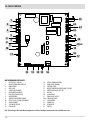
18-CIRCUIT BOARD....................................................................................................74
II
INTRODUCTION
Dear Customer,
our products are designed and manufactured in compliance with European reference Standards for construction products (EN13240
wood-burning stoves, EN14785 pellet-burning appliances, EN13229 fireplaces/wood-burning inserts, EN 12815 wood-burning cookers),
with high quality materials and extensive experience in the transformation processes. The products also meet the essential requirements
of Directive 2006/95/EC (Low Voltage) and Directive 2004/108/EC (Electromagnetic Compatibility).
To get the best performance, we suggest you read the instructions in this manual carefully.
This installation and use manual forms an integral part of the product ensure that the manual is always supplied with the appliance, even
if it changes owner. If the manual is lost, you can request another copy from the local technical service or download it directly from the
company website.
All local regulations, including those regarding national and European regulations, must be observed when the appliance is installed.
In Italy, for the installation of systems with biomass below 35KW, refer to ministerial decree D.M. 37/08, and the qualified installation
technician with the appropriate requisites must issue a certificate of compliance for the system installed. (By system one means
Stove+Chimney+Air inlet).
REVISIONS TO THE PUBLICATION
The content of this manual is strictly technical and the property of MCZ Group Spa.
No part of this manual may be translated into other languages and/or adapted and/or reproduced, even in part, in other mechanical or
electronic forms, photocopies, recordings or other, without the prior written authorisation from MCZ Group Spa.
The company reserves the right to make changes to the product at any time without prior notice. The proprietary company reserves its
rights according to the law.
CARE OF THE MANUAL AND HOW TO CONSULT IT
•
•
•
•
•
Take care of this manual and keep it in an easily accessible place.
Should the manual be misplaced or ruined, request a copy from your retailer or directly from the authorised Technical Assistance
Department. It can be downloaded from the company website.
The "text in bold" must be read with particular care.
“The "text in italics” draws attention to other sections in this manual or clarifications.
“NOTE” provides the reader with additional information.
SYMBOLS USED IN THE MANUAL
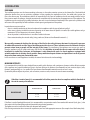
CAUTION:
read the relative message carefully as failure to observe the information provided could result in serious
damage to the product and put the persons who use it at risk.
INFORMATION:
failure to comply with these provisions will compromise the use of the product.
OPERATING SEQUENCES:
sequence of buttons to be pressed to access the menus or change settings.
MANUAL
carefully read this manual or the relative instructions.
Technical Dept. - All rights reserved - Reproduction is prohibited
1
1-WARNINGS AND WARRANTY CONDITIONS
SAFETY PRECAUTIONS
• Installation, electrical connection, function test and maintenance must only be carried out by authorised and
qualified personnel.
• Install the product in accordance with all local and national legislation and regulations in force in the region or state.
• Only use the fuel recommended by the manufacturer. The product must not be used as an incinerator. It is strictly forbidden to use
liquid fuel.
• Do not put any fuel other than wood pellets in the hopper.
• The instructions provided in this manual must always be complied with to ensure the product and any electronic appliances
connected to it are used correctly and accidents are prevented.
• The user, or whoever is operating the product, must read and fully understand the contents of this installation guide before
performing any operation. Errors or incorrect settings can cause hazardous conditions and/or poor operation.
• Do not climb on or lean on the product.
• Do not put linen on the product to dry. Any drying racks or the like must be kept at a safe distance from the product. Fire hazard.
• All liability for improper use of the product is entirely borne by the user and relieves the Manufacturer from any civil and criminal liability.
• Any type of tampering or unauthorised replacement with non-original spare parts could be hazardous for the operator's safety and
relieves the company from any civil and criminal liability.
• Many of the surfaces of the product get very hot (door, handle, glass, smoke outlet pipes, etc.). Avoid coming into contact with
these parts, without adequate protective clothing or suitable implements, such as gloves with thermal protection or
"cold handle" operating systems.
• It is forbidden to operate the product with the door open or the glass broken.
• The product must be powered by an electrical system that is equipped with an effective earthing device.
• Switch the product off in the event of a fault or malfunction.
• Accumulated unburned pellets in the burner after each "failed start-up" must be removed before lighting again. Check that the
burner is clean and positioned properly before lighting again.
• Do not wash the product with water. Water could get inside the unit and damage the electrical insulation and cause electric shocks.
• Do not stand for a long time in front of the product in operation. Do not overheat the room you are in and where the product is
installed. This could cause injuries and health problems.
• Install the product in a location that does not present a fire hazard and is equipped with power and air supplies and smoke extractors.
• In the event of fire in the chimney, turn off the device, disconnect it from the mains electricity and do not open the hatch. Then
contact the competent authorities.
• The product and the cladding must be stored in a dry place and must not be exposed to weathering.
• It is recommended not to remove the feet that support the product in order to guarantee adequate insulation, especially if the
flooring is made of flammable materials.
• In the event of a malfunction of the ignition system, do not force it to light by using flammable materials.
• Special maintenance must only be performed by authorised and qualified personnel.
• Assess the static conditions of the surface on which the weight of the product will rest and provide suitable insulation if it is made of
flammable material (e.g. wood, fitted carpet or plastic).
2
1-WARNINGS AND WARRANTY CONDITIONS
INFORMATION:
Please contact the retailer or qualified personnel authorised by the company to resolve a problem.
• You must only use the fuel specified by the manufacturer.
• When the product is switched on for the first time it is normal for it to emit smoke due to the paint overheating for the first time.
Therefore make sure the room in which it is installed is well ventilated.
• Check and clean the smoke extraction pipes regularly (connection to the chimney).
• The product is not a cooking appliance.
• Always keep the cover of the fuel hopper closed.
• Store this installation and use manual with care as it must accompany the product for the duration of its useful life. If the product is
sold or transferred to another user, ensure the manual is also handed over.
INTENDED USE
The product only works with wood pellets and must be installed indoors.
WARRANTY CONDITIONS
The company guarantees the product, with the exception of elements subject to normal wear listed below, for a period of 2 (two)
years from the date of purchase attested by:
• a document to serve as proof of purchase (invoice and/or receipt) that shows the name of the vendor and the date on which the
purchase was made;
• forwarding of the completed certificate of guarantee within 8 days of purchase.
Furthermore, in order for the guarantee to be valid, the device must be installed and calibrated by qualified personnel, and where
necessary, the user must be issued with a declaration of conformity and correct functioning of the product.
We recommend testing the product before completion with the relative finishes (claddings, painting of walls, etc.).
Installations that do not meet the current standards, improper use and lack of maintenance as expected by the manufacturer, void the
product warranty.
The guarantee is valid on the condition that the instructions and warnings contained in the use and maintenance manual are observed,
and therefore the product is used correctly.
The replacement of the entire appliance or the repair of one of its components does not extend the warranty period, and the original
expiry date remains unchanged.
The warranty covers the replacement or free repair of parts recognised as faulty at source due to manufacturing defects.
To benefit from the warranty, in the event of a fault, the customer must have the warranty certificate and show it with the proof of
purchase document to the Technical Assistance Office.
Technical Dept. - All rights reserved - Reproduction is prohibited
3
1-WARNINGS AND WARRANTY CONDITIONS
EXCLUSIONS
The guarantee does not cover malfunctions and/or damage to the appliance that arise due to the following causes:
• Damage caused during transportation and/or handling
• all parts that develop faults due to negligence or improper use, incorrect maintenance, installation that does not comply with the
manufacturer's instructions (always refer to the installation and use manual provided with the appliance)
• incorrect sizing with regard to the use or faults in the installation or failure to adopt the necessary devices to guarantee proper
execution
• improper overheating of the equipment, use of fuels not conforming to the types and quantities indicated in the instructions provided
• further damage caused by incorrect user interventions in an attempt to fix the initial fault
• worsening of the damage caused by the user continuing to operate the appliance even after the fault has been noticed
• in presence of a boiler, any corrosion, incrustations or breakages caused by water flow, condensation, hardness or acidity of the water,
improperly performed descaling treatments, lack of water, mud or limescale deposits
• inefficiency of chimneys, flues or parts of the system affecting the appliance
• damage caused by tampering with the appliance, atmospheric agents, natural disasters, vandalism, electric shocks, fires, faults in
the electric and/or hydraulic system.
Also excluded from this guarantee are:
• parts subject to normal wear such as gaskets, glass, claddings and cast iron grids, painted, chrome-plated or gilded parts, handles
and electric cables, bulbs, indicator lights, knobs, all parts which can be removed from the hearth.
• Variations in colour of the painted or ceramic/serpentine parts and craquelure ceramics as they are natural characteristics of the
material and product use.
• masonry work
• plant parts (if present) not supplied by the manufacturer
Any technical interventions on the product to eliminate the defects mentioned above and consequent damages must be agreed upon with
the Technical Assistance Centre, who reserves the right to accept the relative appointment or not. However, said interventions will not be
carried out under the guarantee but as technical assistance to be granted as part of any eventual and specific agreed conditions and in
accordance with the fee applicable for the work to be carried out.
The user will also be charged for any costs incurred to remedy the incorrect technical interventions, tampering or damage to the appliance,
not attributable to original faults.
With the exception of the legal or regulatory limits, the warranty does not cover the reduction of atmospheric and acoustic pollution.
The company declines all liability for any damage which may be caused, directly or indirectly, to persons, animals or objects as
a consequence of non compliance with any provision specified in the manual, especially warnings regarding installation, use
and maintenance of the appliance.
4
1-WARNINGS AND WARRANTY CONDITIONS
SPARE PARTS
In the event of a malfunction, consult the retailer who will forward the call to the Technical Assistance Service.
Only use original spare parts. The retailer or service centre can provide all necessary information regarding spare parts.
We do not recommend waiting for the parts to get worn out before having them replaced. It is important to perform regular maintenance.
The company declines all liability if the product and any other accessory is used improperly or modified without
authorisation.
All parts must be replaced with original spare parts.
PRECAUTIONS FOR CORRECT DISPOSAL OF THE PRODUCT IN ACCORDANCE WITH THE EUROPEAN DIRECTIVE
2002/96/EC AND ITS SUBSEQUENT AMENDMENT 2003/108 EC.
At the end of its working life, the product must not be disposed of as urban waste.
It must be taken to a special differentiated waste collection centre set up by the local authorities or to a retailer that provides this service.
Disposing of the product separately prevents possible negative consequences for the environment and health deriving from inappropriate
disposal and allows its materials to be recovered in order to obtain significant savings in energy and resources.
As a reminder of the need to dispose of appliances separately, the product is marked with a crossed-out wheeled dustbin.
Technical Dept. - All rights reserved - Reproduction is prohibited
5
1-WARNINGS AND WARRANTY CONDITIONS
RULES FOR INSTALLATION
The product in question is a stove that uses wood pellets.
Below is a list of European regulations regarding the installation of the product:
EN 12828 Heating systems design.
IEC 64-8 Electrical systems with rated voltage not exceeding 1000 V AC and 1500 V DC.
EN 1443 General chimney regulation
EN 1856-1 metal smoke ducts
EN 1856-2 metal smoke extraction channels
EN 1457 chimneys - Interior terracotta / ceramic flues
EN 13384-1 Chimneys - Thermal and dynamic fluid calculation methods - Part 1: Chimneys connected to a single appliance
Below are some applicable regulations for Italy:
UNI 10683:2012 Heat generators fuelled by wood or other solid bio-fuels - Test, installation, control and maintenance (for thermochemical
power at the firebox lower than 35kW)
UNI/TS 11278 general technical regulation for the choice of smoke duct/flue
UNI 10847:2000 Smoke extractor systems for liquid and solid fuelled generators - Maintenance and control - Guidelines and procedures
UNI 8065 water treatment in civil plants.
UNI 9182 Hot and cold (sanitary) water supply and distribution systems.
Installation must be carried out with reference to the diagram of the heating system prepared in accordance with the
standards and local recommendations in force:
In any case, respect:
For the heating appliance Local requirements concerning the chimney connection.
Local requirements for fire-fighting standards.
For electrical parts - EN 60335 ''Safety of electrical household appliances and similar"
Part 1 - General requirements
Part 2 - Special regulations for appliances with gas, gas oil and solid fuel burners with electrical connections.
6
2-FUEL
The instructions contained in this chapter explicitly refer to the regulations of the Italian installation Standard UNI 10683. In any case,
always comply with the regulations in force in the country of installation.
PELLETS
Wood pellets are manufactured by hot-extruding compressed sawdust which is produced during the working of natural dried wood. The
compactness of the material is guaranteed by the lignin contained in the wood itself and allows pellets to be produced without glue or
binders.
The market offers different types of pellets with characteristics that vary according to the wood mixtures used. The diameter varies
between 6 and 8 mm, with a standard length ranging from 5 to 30 mm. A good quality pellet has a density of between 600 and 750 or
more kg/metres cubed and a water content that accounts for 5 to 8% of its weight.
Pellets have technical advantages besides being an ecological fuel, as the wood residue is used completely, thereby achieving cleaner
combustion than that of fossil fuels.
While good-quality wood has a calorific value of 4.4 kW/kg (15% moisture, after about 18 months of seasoning), whereas that of pellets
is around 4.9 kW/kg. To ensure good combustion, the pellets must be stored in a dry place and protected from dirt. Pellets are usually
supplied in 15 kg bags, therefore, storing them is very convenient.
15 Kg BAG OF FUEL
Good quality pellets guarantee good combustion, thereby decreasing harmful emissions into the atmosphere.
The poorer the quality of the fuel, the more often the internal parts of the brazier and combustion chamber must
be cleaned.
The main quality certifications for pellets currently available on the European market guarantee that the fuel complies with class A1/A2
according to EN14961-2. An example of these certifications are the ENPlus, DINplus, Ö-Norm M7135, and they guarantee that they are
followed according to these characteristics:
•
•
•
•
•
•
•
calorific value: 4,6 ÷ 5.3 kWh/kg.
Water content: max 10% of weight.
Percentage of ashes: max 1.5% of weight.
Diameter: 5 ÷ 6 mm.
Length: max 40 mm.
Content: 100% untreated wood without the addition of binding substances (max 5% bark).
Packaging: in sacks made from ecologically compatible or bio-degradable material.
The company strongly recommends using certified fuel for its products (ENplus, DINplus, Ö-Norm M7135).
Poor quality pellets or others that do not comply with the characteristics specified previously may compromise the
operation of your product and can therefore make the guarantee and product liability invalid.
Technical Dept. - All rights reserved - Reproduction is prohibited
7
3-INSTALLATION
FOREWORD
The installation position must be chosen according to the room, to the smoke extraction system, to the chimney flue. Check with local
authorities whether there are any restrictive regulations in force regarding the combustion air inlet, the smoke outlet system, the
flue or the chimney cap. The manufacturer declines all responsibility in the event of installations that do not comply with the laws in
force, incorrect room air exchange, electrical connection non-compliant with the standards and inappropriate use of the appliance. The
installation must be carried out by a qualified technician, who must issue a declaration of conformity of the system to the purchaser and
will assume full responsibility for final installation and consequent good operation of the product.
In particular one must ensure that:
• there is a suitable combustion air inlet and smoke outlet in compliance with the type of product installed
• other stoves or devices installed do not cause depression in the room where the product is installed (for sealed appliances only, a
maximum of 15 Pa of depression in the room is allowed)
• when the product is switched on there is no reflux of smoke in the room
• fumes extraction takes place in total safety (sizing, smoke seal, distances from flammable materials..).
We especially recommend checking the data tags of the flue for the safety distances that must be observed in presence
of combustible materials and the type of insulating material to be used. These indications must be followed strictly to
prevent serious harm to people and the integrity of the home. The installation of the appliance must ensure easy access to
clean the appliance itself, the smoke outlet pipes and the flue. It is forbidden to install the stove in rooms with a fire hazard.
Installation in studio flats, bedrooms and bathrooms is only allowed with sealed or closed appliances equipped with
suitable combustion air ducting directly outside. Always maintain adequate distance and protection in order to prevent
the product from coming into contact with water.
In the event there are several appliances installed, the external air inlet must be sized accordingly.
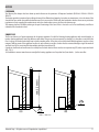
MINIMUM DISTANCES
It is recommended to install the stove detached from any walls and/or furniture, with a minimum clearance to allow effective aeration
of the appliance and a good distribution of heat in the room. Observe the distances from flammable or heat-sensitive objects (sofas,
furniture, wood panelling, etc..) as specified. The front distance from flammable materials must be at least 1 metre.
If particularly delicate objects are present, such as furniture, curtains or sofas, increase the stove clearance accordingly.
If the floor is made of wood, it is recommended to fit a floor protection sheet in compliance with the Standards in
force in the country of installation.
A
Non-flammable walls
Flammable walls
A = 5 cm
B = 5 cm
A = 10 cm
B = 10 cm
DUO HYDRO AIR
B
If the floor is made of combustible material, it is recommended to use protection made of non-combustible material (steel, glass...) that
also protects the front from falling combusted material during cleaning operations.
The appliance must be installed on a floor with adequate load capacity.
If the existing construction does not meet this requirement, one must take appropriate measures (for example a load distribution plate).
8
4-FLUE
FOREWORD
The Chimney Flue chapter has been drawn up with reference to the provisions of European Standards (EN13384 - EN1443 - EN1856 EN1457).
The chapter provides instructions for installing a chimney flue efficiently and properly, but under no circumstances is it a substitute of the
Standards in force, which the qualified technician must be in possession of. Check with local authorities whether there are any restrictive
regulations in force regarding the combustion air inlet, the smoke outlet system, the flue or the chimney cap.
The company declines all liability relating to the poor functioning of the stove if this is due to the use of an insufficiently sized flue in
violation of the Standards in force.
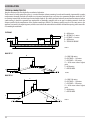
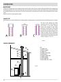
SMOKE FLUE
min.3,5 metri
The flue or chimney is of great importance for the proper operation of a solid fuel-burning heating appliance with natural draught, as
modern heating appliances have high efficiency with cooler flue gasses and consequently less draught, it is therefore essential that the
flue is built up to standard and always kept in perfect working order. A flue that serves a pellet/wood fuelled appliance must be at least
category T400 (or greater if the appliance requires so) and resistant to soot fires. Smoke must be extracted through a single flue made of
insulated steel (A) or an existing flue that complies with the intended use (B).
A simple air shaft made of cement must be suitably lined. In both solutions there must be an inspection cap (AT) and/or inspection hatch
(AP) - FIG.1.
It is forbidden to connect more than one wood/pellet-burning appliance or of any other kind (vent hoods... ) to the same flue.
AP
(A)
AT
(B)
FIGURE 1 - SMOKE FLUE
Technical Dept. - All rights reserved - Reproduction is prohibited
9
3-INSTALLATION
TECHNICAL CHARACTERISTICS
Have the efficiency of the flue checked by an authorised technician.
The flue must be sealed against flue gasses, in a vertical direction without narrowing, be made with materials impermeable to smoke,
condensation, thermally insulated and suitable to resist normal mechanical stress over time (we recommend fireplaces made of A/316
or refractory material with insulated round section double chamber). Be suitably insulated externally to avoid condensation and reduce
smoke cooling. It should be separated from combustible or flammable materials with an air gap or insulating materials: check the
distance specified by the manufacturer of the fireplace according to EN1443. The chimney opening must be in the same room as the
appliance, or at most in the adjoining room, and have a soot and condensation collection chamber beneath the opening, and be accessible
via a watertight metal hatch.
FLAT ROOF
D
A
B
C
E
A = 0.50 metres
B = DISTANCE > 2 metres
C = DISTANCE < 2 metres
D = 0.50 metres
E = TECHNICAL VOLUME
FIGURE 2
ROOF AT 15°
B
C
D
A
F
E
15°
A = MIN. 1.00 metres
B = DISTANCE > 1.85 metres
C = DISTANCE < 1.85 metres
D = 0.50 metres above highest
point
E = 0.50 metres
F = REFLUX AREA
FIGURE 3
ROOF AT 30°
B
A = MIN. 1.30 metres
B = DISTANCE > 1.50 metres
C = DISTANCE < 1.50 metres
D = 0.50 metres above highest
point
E = 0.80 metres
F = REFLUX AREA
C
D
A
30°
E
F
FIGURE 4
10
3-INSTALLATION
ROOF AT 60°
ROOF AT 45°
B
B
C
C
D
D
E
A
F
60°
A = MIN. 2.60 metres
B = DISTANCE > 1.20 metres
C = DISTANCE < 1.20 metres
D = 0.50 metres above highest point
E = 2.10 metres
F = REFLUX AREA
FIGURE 5
A
E
45°
A = MIN. 2.00 metres
B = DISTANCE > 1.30 metres
C = DISTANCE < 1.30 metres
D = 0.50 metres above highest point
E = 1.50 metres
F = REFLUX AREA
F
FIGURE 6
SIZING
The depression (draught) of a flue depends on its height. Check the depression with the values indicated in the technical characteristics.
The minimum height of the chimney is 3.5 meters.
The interior cross-section of the flue can be round (best), square or rectangular (the ratio between the internal sides must be ≤1.5) with
the sides joined with a minimum radius of 20 mm. The dimension of the cross-section must be minimum Ø100mm.
The cross sections/lengths of chimneys must be correctly sized in accordance with the general method of calculation of UNI EN13384-1 or
other methods of proven efficiency.
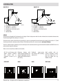
Below is a list of some flues available on the market:
AISI 316 steel chimney with
double chamber insulated
with ceramic fibre or
equivalent resistant up to
400°C.
Refractory chimney with Traditional
square-section Avoid products with an
double insulated chamber and clay chimney with insulating internal rectangular section
external lightweight concrete empty inserts.
where the larger side is 1.5
cladding with cellular material
times the smaller side (e.g.
such as clay.
20x40 or 15x30).
EXCELLENT
GOOD
Technical Dept. - All rights reserved - Reproduction is prohibited
POOR
VERY POOR
11
3-INSTALLATION
MAINTENANCE
The flue must be kept clean, since the deposit of soot or unburned oils reduces the cross-section reducing the draft and thus compromising
the efficient operation of the stove and, if large build-ups accumulate, can catch fire. The flue and chimney must be cleaned and checked
by a qualified chimney sweep at least once a year. Once maintenance has been performed, request a written declaration that the system
is safe.
Failure to clean the system jeopardises safety.
CHIMNEY CAP
The chimney cap is a crucial element for the heating appliance to work properly: we recommend a wind proof chimney cap (A), see Figure
7.
The area of the openings for smoke
extraction must be at least double the
cross-section of the smoke duct/flue
system, and arranged so that smoke
extraction is ensured even in strong wind.
The chimney must prevent rain, snow or
animals from entering the chimney. The
height of outflow into the atmosphere
must be beyond the reflux area due to the
shape of the roof or any obstacles near the
outlet (see Figures 2-3-4-5-6).
FIGURE 7
CHIMNEY COMPONENTS
1
3
4
KEY:
(1) CHIMNEY CAP
(2) REFLUX CHANNEL
(3) SMOKE DUCT
(4) THERMAL INSULATION
(5) OUTSIDE WALL
(6) CHIMNEY CONNECTION
(7) SMOKE CHANNEL
(8) HEAT GENERATOR
(9) INSPECTION ACCESS PANEL
2
9
5
6
7
FIGURE 8
8
9
9
12
3-INSTALLATION
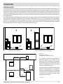
EXTERNAL AIR INLET
It is mandatory to provide an adequate external air intake that supplies the combustion air required for the product to work properly. The
flow of air between the outside and the installation room may be direct, through an inlet in an external wall of the room; or indirect, via
air intake from adjoining rooms and connecting permanently with the installation room (see Figure 9 b). Adjoining areas may not include
sleeping areas, garages or general areas with a fire hazard. During installation one must check the minimum clearances required for air
intake from outside. Take into account the presence of doors and windows that could interfere with the proper flow of air to the stove
(see diagram below).
The air intake must have a minimum total net area of 80 cm2: the surface must be increased accordingly if within the room there are other
active generators (for example: electric fan for stale air extraction, kitchen hood, other stoves, etc...), which could cause a depression in
the room. One must verify that, with all the equipment on, the pressure drop between the room and the outside does not exceed a value
of 4 Pa. If necessary increase the intake section of the air inlet, which must be made at floor level and always protected with a bird-proof
outer protection grid and in such a way that it cannot be obstructed by any object.
B
B
C
A
FIGURE 9 A - DIRECTLY FROM OUTSIDE
MIN.1,5 m
A
FIGURE 9 B - INDIRECTLY FROM THE ADJACENT ROOM
MIN.1,5 m
MIN.0,3 m
MIN.1,5 m
A=AIR INLET
B=ROOM TO BE VENTILATED
C=INCREASE OF THE GAP UNDER THE DOOR
It is possible to connect the air required for
combustion directly to the outside air inlet,
with a pipe of at least Ø50mm, with maximum
length of 3 linear metres; each pipe bend shall be
considered equivalent to a linear metre. To attach
the pipe see the back of the stove.
For stoves installed in studio flats, bedrooms and
bathrooms (where allowed), it is mandatory to
connect the combustion air outside. In particular
for sealed stoves the connection must be sealed
in order not to compromise the overall sealed
characteristic of the system.
FIGURE 10
Technical Dept. - All rights reserved - Reproduction is prohibited
13
3-INSTALLATION
DISTANCE (metres)
The air inlet must be at a distance of:
1.5 m
UNDER
Windows, doors, smoke outlets, cavities, ....
1.5 m
HORIZONTALLY
Windows, doors, smoke outlets, cavities, ....
0.3 m
ABOVE
Windows, doors, smoke outlets, cavities, ....
1.5 m
AWAY
from smoke outlet
CONNECTION TO THE FLUE
The connection between the flue and the appliance must be via a smoke duct that complies with EN 1856-2. The connecting section must
extend no more than 4 m horizontally, with a minimum slope of 3% and with a maximum of 3 90% bends (accessible for inspection - do
not count the T fitting at the appliance outlet).
The diameter of the smoke duct must be equal to or greater than that of the appliance outlet (Ø 80 mm).
TYPE OF SYSTEM
SMOKE DUCT
Minimum vertical length
1.5 metres
Maximum length
(with 1 accessible 90° bend)
6.5 metres
Maximum length
(with 3 accessible 90° bends)
4.5 metres
Maximum number of accessible 90° bends
3
Horizontal sections
(minimum slope 3%)
4 metres
Use a smoke duct according to current regulations in the country of installation that is compatible to product and installation characteristics.
The temperature class of the smoke duct must exceed operating temperatures of the appliance.
It is forbidden to connect several appliances to the same smoke duct, or the outlet from the overhead hoods. It is forbidden to extract the
combustion products directly through the wall, whether into indoor spaces or outdoors.
With flammable or heat-sensitive structures present, the smoke duct must respect the safety distances specified in the data plate.
14
3-INSTALLATION
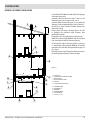
EXAMPLES OF CORRECT INSTALLATION
1
U
F
E
V
I
1. Installation of Ø120mm flue with hole for the passage
of the pipe increased by:
minimum 100 mm around the tube if next to non
flammable parts such as cement, brick, etc.; or
minimum 300mm around the pipe (or as required by
data tags) if next to flammable parts such as wood etc.
In both cases, install suitable insulation between the
flue and the ceiling.
Always check and respect the data tags on the flue,
in particular the minimum safety distances from
combustible materials.
The previous rules also apply for holes made in walls.
2. Old flue, minimum pipe Ø100mm with the inclusion
of an external access door for chimney cleaning.
3. External flue made of insulated stainless steel pipes,
i.e. with double walls minimum Ø100mm: all securely
mounted on the wall. With wind-proof chimney cap. See
fig. 7 type A.
4. Ducting system using T fitting that allows easy access
for cleaning without having to remove the pipes
2
3
D
FIGURE 11
B
U
I
I
A
U
C
I
4
S
T
P
U = INSULATING
V = ANY REDUCTION FROM 100 TO 80 MM
I = INSPECTION CAP
S = INSPECTION ACCESS PANEL
P = AIR INLET
T = T JOINT WITH INSPECTION CAP
A = MINIMUM 40 MM
B = MAXIMUM 4 M
C = MINIMUM 3°
D = MINIMUM 400 MM
E = HOLE DIAMETER
F = SEE FIG.2-3-4-5-6
I
Technical Dept. - All rights reserved - Reproduction is prohibited
15
5-DRAWINGS AND TECHNICAL FEATURES
DRAWINGS AND CHARACTERISTICS
043
1213
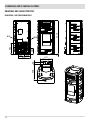
DUO HYDRO - AIR STOVE DIMENSIONS
187 226
413
558
64
417
080 048
582
16
10
202
382
080
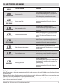
5-DRAWINGS AND TECHNICAL FEATURES
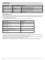
TECHNICAL CHARACTERISTICS
Nominal output power
Nominal output power (H2O)
Minimum output power
Minimum output power (H2O)
Efficiency at Max
Efficiency at Min
Temperature of exhaust smoke at Max
Temperature of exhaust smoke at Min
Particles/OGC/Nox (13%O2)
CO at 13% O2 at Min and at Max
CO2 at Min and at Max
Smoke mass
Max operating temperature
Recommended draught at Max power
Recommended draught at Min power
Hopper capacity
Type of pellet fuel
Pellet hourly consumption
Autonomy
Heatable volume m3
Combustion air inlet
Smoke outlet
Air inlet
Rated electrical power (EN 60335-1)
Supply voltage and frequency
Net weight
Weight with packaging
Distance from flammable material (back)
Distance from flammable material (side)
DUO HYDRO-AIR
22.3 kW (19,178 kcal/h)
18.0 kW (15,480 kcal/h)
4.4 kW (3,784 kcal/h)
3.0 kW (2,580 kcal/h)
92,5%
95,0%
160°C
71°C
2 mg/Nm3 - 0.2 mg/Nm3 - 132 mg/Nm3
0,040 – 0,012%
7,03% - 12,49%
12.6 g/sec
2.5 bar - 250 kPa
0.10 mbar - 10 Pa
0.05 mbar - 5 Pa
44 litres
Pellet diameter 6-8 mm and size 5/30 mm
Min ~ 0.9 kg/h* - Max ~ 4.9 kg/h*
At min ~ 28 h* - At max ~ 5 h*
481/40 – 550/35 – 642/30 **
Ø 50 mm
Ø 80 mm
80 cm2
120 W (Max 420 W)
230 Volt / 50 Hz
190 kg
200 kg
100 mm
100 mm
* Data that may vary depending on the type of pellets used
** Volume that can be heated, according to the power requirement per m3 (respectively 40-35-30 Kcal/h per m3)
Tested according to EN 14785 in accordance with European regulation for Construction Products (UE 305/2011)
Technical Dept. - All rights reserved - Reproduction is prohibited
17
6-INSTALLATION AND ASSEMBLY
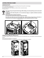
PREPARATION AND UNPACKING
The packaging consists of a recyclable cardboard box according to RESY standards, recyclable EPS foam inserts, wooden pallets. All
packaging materials can be reused for similar use or eventually disposed of as urban solid waste, in compliance with the regulations in
force.
After having removed the packaging make sure the product is intact.
Handle the product with suitable means paying attention to the applicable safety regulations in force. Do not turn the
packaging over and handle the ceramic parts with care.
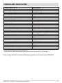
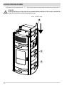
The DUO stove is delivered with two overlapping packaging:
• the first contains the stove structure (fig. 1).
• the second (fig.2) contains the box with the ceramic cladding (1 top, 2 front panels, 6 side panels)
Open the packaging, remove the two screws on the right and the two screws on the left (see figure 4) that secure the base of the stove to
the pallet, and position the stove in the selected place, ensuring that it is complies with the above instructions.
FIGURE 2 - CERAMIC PANEL
PACKAGING
FIGURE 1 - REMOVING PACKAGING
SCREWS
18
6-INSTALLATION AND ASSEMBLY
The stove body or unit must always be kept in a vertical position when handled, and handled using carts only. Pay particular attention to
the door and its glass, protecting them from mechanical knocks that would compromise their integrity.
The product must always be handled with care. If possible, unwrap the stove near the chosen area of installation.
The packaging materials are neither toxic nor harmful, therefore no particular disposal measures are required.
Therefore, the end user is responsible for product storage, disposal or possible recycling in compliance with the relative applicable laws in
force. Do not store the unit/stove or its cladding without their packaging.
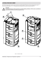
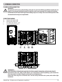
Position the stove and connect it to the flue pipe. Use the four adjustable feet (J) to get the stove correctly levelled so that the smoke
outlet (S) is lined up with the connecting pipe (H).
If the stove needs to be connected to an outlet pipe which goes through the rear wall (to connect to the flue), take utmost care to make
sure that the joint is not forced.
If the stove smoke outlet is forced or used improperly to lift it or position it, the operation of the stove can be
damaged irreparably.
J
H
S
J
1. TURN THE FEET CLOCKWISE TO LOWER THE STOVE
2. TURN THE FEET COUNTER CLOCKWISE TO LIFT THE STOVE
Technical Dept. - All rights reserved - Reproduction is prohibited
19
6-INSTALLATION AND ASSEMBLY
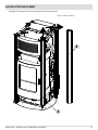
ASSEMBLING THE FRONT AND SIDE CLADDING
The stove is delivered with all ceramic parts packaged and therefore, before installing the side tiles and the top, it is necessary to insert
the front panels.
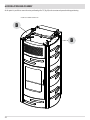
In order to insert the front panel it is necessary to work on the right side of the stove (handle side) and proceed as follows:
• Remove the micro-perforated sheet metal grille "B" removing the two screws "c" (fig.3).
• Remove the two screws “d”, lift and remove the bracket“E” (fig.4)
c
d
B
E
A
FIGURE 3 - REMOVAL OF GRILLE B
20
FIGURE 4 - REMOVAL OF E BRACKET
6-INSTALLATION AND ASSEMBLY
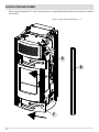
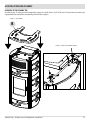
•
Lift profile “A” to remove it from the base and place it in a safe position (fig.5)
FIGURE 5 - REMOVAL OF PROFILE A
A
A
Technical Dept. - All rights reserved - Reproduction is prohibited
21
6-INSTALLATION AND ASSEMBLY
•
Take the two front ceramic pieces “F” and “G” and insert them on the right (handle side) towards the left so that they fit exactly in
the seat (fig.6)
FIGURE 6 - ASSEMBLY OF FRONT CERAMIC PANELS “F” - “G”
G
A
F
22
6-INSTALLATION AND ASSEMBLY
•
After inserting ceramic pieces “F” and “G”, reinsert profile “A”, bracket “E” tightening the two screws “d” (fig.7).
FIGURE 7 - ASSEMBLY OF PROFILE “A” AND BRACKET “E”
d
E
G
F
A
Technical Dept. - All rights reserved - Reproduction is prohibited
23
6-INSTALLATION AND ASSEMBLY
• At this point insert side ceramic pieces “R”, “S”, “T” (fig.8) sliding them from the top towards the bottom on the guide of profile “A”.
ATTENTION!
On the top and lower part of the ceramic tile we recommend placing small pieces of felt in order to avoid that the
ceramic tiles break and also to level the spacing if necessary.
FIGURE 8 - SIDE PANEL ASSEMBLY
R
S
T
24
6-INSTALLATION AND ASSEMBLY
On the left side (opposing the handle - fig.9) remove the micro-perforated grille "B" from the structure removing the two screws "c".
Insert the three ceramic pieces “U”, “V”, “Z” sliding them from the top towards the bottom on the guide of profile “A”.
ATTENTION!
On the top and lower part of the ceramic tile we recommend placing small pieces of felt in order to avoid that the
ceramic tiles break and also to level the spacing if necessary.
c
U
B
V
Z
A
A
FIGURE 9 - SIDE PANEL ASSEMBLY
Technical Dept. - All rights reserved - Reproduction is prohibited
25
6-INSTALLATION AND ASSEMBLY
At this point it is possible to screws the micro-perforated grilles "B" (fig.10) to the structure and proceed with top positioning.
FIGURE 10 - ASSEMBLY OF GRILLES “B”
B
B
26
6-INSTALLATION AND ASSEMBLY
ASSEMBLY OF THE CERAMIC TOP
Assemble the top "K" resting it on the four top rubber supports (see details below - fig.12) of the stove. The part under the ceramic top is
equipped with four small cavities corresponding with the rubber supports.
FIGURE 11 - TOP ASSEMBLY
K
FIGURE 12 - DETAIL OF TOP RUBBER SUPPORTS
Technical Dept. - All rights reserved - Reproduction is prohibited
27
6-INSTALLATION AND ASSEMBLY
LOADING THE PELLETS
Fuel is loaded from the upper part of the stove by lifting the door. Pour the pellets into the hopper.
This is easier if performed in two steps:
Pour half of the contents into the hopper and wait for the fuel to settle on the bottom.
Then pour in the rest.
Never remove the protection grid inside the hopper. When loading, do not let the pellet bag come into contact with
hot surfaces.
No other type of fuel other than pellets is to be inserted into the hopper, in compliance with above-mentioned
specifications.
Store the spare fuel at an adequate safe distance.
Do not pour pellets directly onto the brazier but only into the hopper.
Most of the stove surfaces are very hot (door, handle, glass, smoke outlet pipes, hopper door etc.), therefore it is
recommended to avoid coming into contact with these parts without appropriate protective clothing.
LOADING THE PELLETS
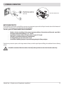
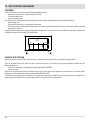
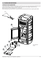
CONDUIT FOR THE AUXILIARY TANK (optional)
It is possible to purchase conduit to be fastened, using four screws, to the back of the stove, in correspondence of the knock-out panel,
first the
square and then the round piece is to be removed.
This conduit makes it possible to insert pellets into the tank through an auxiliary tank (not supplied).
1
28
2
7 - HYDRAULIC CONNECTION
PLUMBING SYSTEM CONNECTION
IMPORTANT!
The connection of the stove to the plumbing system must be carried out ONLY by specialized personnel who are
capable of carrying out installation properly, in compliance with current standards in the country of installation.
The manufacturer will not be held responsible for damage to persons or things in the event of failed operation if the
aforementioned warning is not complied with.
CONNECTION DIAGRAM
A1
A2
C
E
Heating water supply 3/4”M
Heating water return 3/4”M
3 bar safety shut off valve– 1/2”F
System emptying device 1/2”F
C
E
A1
A2
67
50
169
55 60
106
187
IMPORTANT!!!
CLEAN THE ENTIRE SYSTEM BEFORE CONNECTING THE STOVE, IN ORDER TO REMOVE ALL RESIDUE AND DEPOSITS.
Upstream from the stove, always install shutters so as to disconnect it from the plumbing system should it be
necessary to move it, or when it requires routine and/or special maintenance.
Connect the stove using hoses so that the stove is not too strictly connected to the system, and to allow slight
movements.
Technical Dept. - All rights reserved - Reproduction is prohibited
29
7 - HYDRAULIC CONNECTION
CONNECTING THE SYSTEM
Make the connections to the corresponding fittings shown in the diagram on the previous page. Make sure the pipes are not placed under
tension or undersized.
IT IS STRONGLY RECOMMENDED TO WASH THE ENTIRE SYSTEM BEFORE CONNECTING THE STOVE IN ORDER TO GET RID
OF RESIDUES AND DEPOSITS.
Upstream from the stove, always install shutters so as to disconnect it from the plumbing system should it be
necessary to move it, or when it requires routine and/or special maintenance. Connect the stove using hoses so that
the stove is not too strictly connected to the system, and to allow slight movements.
The pressure discharge valve (C) is always connected to a water drain pipe. The pipe must be adequate to support the
water's high temperature and pressure.
CLEANING THE SYSTEM
It is mandatory for the connections to be easy to disconnect by way of unions with rotating connection.
Install suitable shutters to cut off the tubes from the heating system. Assembling the safety valve on the system is compulsory.
In order to protect the heating system from damage caused by corrosion, incrustation or deposit build-up, it is important to clean the
appliance before installation, using suitable products, in compliance with Standard UNI 8065 (water treatment of thermal plants for civil
use).
The use of FERNOX PROTECTOR F1 (available at our authorised centres) product is recommended, this provides long term protection
against corrosion and calcium build-up for heating systems. It prevents the corrosion of the metal parts of the appliance, i.e. the ferrous
metals, copper and copper and aluminium alloys. It also reduces the noise produced by the boiler. Refer to the instructions on the product.
Cleaning should be performed by a qualified technician.
We also recommend the use of FERNOX CLEANER F3 and LEAK SEALER F4, always available from our authorised distribution centres.
FERNOX F3 is a neutral product for rapid and efficient cleaning of heating appliances. It has been designed to eliminate residues, oily
deposits and incrustations from existing appliances of all ages. It can help restore the heating efficiency of the boiler and reduce the noise
it generates.
FERNOX F4 is intended to be used with all heating appliances to seal micro fractures that cause small and inaccessible leaks.
FILLING THE SYSTEM
To fill the system, the stove can be equipped with an end piece (optional) with a non-return valve (D), for manual filling of the heating
system (if the option is not installed, the filling tap on the main boiler will be used). During this operation, any air in the system is released
from the automatic vent valve located under the top.
To ensure the valve vents, it is advisable to loosen the grey cap one turn and leave the red cap blocked (see figure). The filling pressure
of the system WHEN COLD must be 1 bar. During operation, if the system pressure drops (due to evaporation of dissolved gases in the
water) to values lower than the minimum indicated above, the user must use the filling tap to bring the pressure back up to its normal
pressure.
For proper operation of the stove WHEN HOT, the pressure in the boiler must be 1.5 bar.
To monitor system pressure, the end piece (optional) is equipped with a pressure gauge (M).
Upon completion of this operation, always close the tap.
30
7 - HYDRAULIC CONNECTION
END PIECE WITH A FILLING TAP
(D) AND PRESSURE GAUGE (M)
(ACCESSORY)
VENT VALVE UNDER THE TOP
WATER CHARACTERISTICS
The characteristics of the water used to fill the system are very important to prevent the build-up of mineral salts and the formation of
incrustations along the pipes, in the boiler and in the heat exchangers.
Therefore, please GET YOUR PLUMBER'S ADVICE CONCERNING:
•
•
•
•
•
Hardness of water circulating in the system, to prevent problems of incrustation and limescale, especially in
the domestic water heat exchanger. (> 25° French).
Installation of a water softener (if water hardness exceeds 25° French).
Filling the system with treated water (demineralised).
Possibly providing an anti-condensation circuit.
Installation of plumbing bumpers to prevent banging along the fittings and pipes.
If you have very extensive systems, with a large amount of water, or which require frequent refilling, the installation of water softening
systems.
It should be remembered that incrustations drastically reduce performance due to low thermal conductivity.
Technical Dept. - All rights reserved - Reproduction is prohibited
31
8-ELECTRICAL CONNECTION
ELECTRICAL CONNECTION
First connect the power cable to the back of the stove and then to a wall socket.
The main switch must only be activated to switch the stove on; otherwise, it is advisable to keep it switched off.
It is recommended to disconnect the power cable when the stove is not used.
ELECTRICAL STOVE CONNECTION
STOVE POWER SUPPLY
After connecting the power cable to the back of the stove, turn the switch at the back to position (I).
The luminous switch button will light up.
The switch on the back of the stove is used to power the system.
On the rear of the stove there is a fuse holding compartment which is located underneath the supply socket. Use a screwdriver to open the
STOVE POWER SUPPLY
FUSE HOLDER COMPARTMENT
STOVE SWITCH
fuse-holder compartment and if necessary replace them (3.15 A delayed)
32
8-PRECAUTIONS BEFORE START-UP
GENERAL PRECAUTIONS
Remove any objects that may burn from the brazier (manual, various adhesive labels or any polystyrene).
Check that the brazier is positioned correctly and rests properly on the base.
The first start-up may not be successful as the feed screw is empty and does not always manage to load the required
amount of pellets in time to light the flame.
CANCEL THE FAILED IGNITION ALARM. REMOVE THE PELLETS LEFT IN THE BRAZIER AND REPEAT THE START-UP.
If after repeated attempts, the flame fails to ignite, despite a regular flow of pellets in the brazier, which must rest snugly against the
slots and be clean without any ash incrustations. If no anomaly is found during this inspection, there may be a problem with the
product components or installation may not be correct.
REMOVE THE PELLETS FROM THE BRAZIER AND CONTACT AN AUTHORISED TECHNICIAN.
Do not touch the boiler during the first lighting, as it is during this phase that the paint sets. If you touch the paint,
you may expose the steel surface.
If necessary, touch up the paint with the spray can of the specific colour. (See "Pellet stove accessories").
It is good practice to ensure effective ventilation in the room during the initial start-up, as the boiler will emit some
smoke and smell of paint.
Do not stand close to the stove and, as mentioned, air the room. The smoke and smell of paint will disappear after about an hour of
operation, however, they are not harmful in any case.
The boiler will be subject to expansion and contraction during the lighting and cooling down stages, and may therefore make slight
creaking noises.
This is absolutely normal as the structure is made of laminated steel and must not be considered a defect.
It is extremely important to make sure the boiler does not reach high temperatures straight away, but to increase the temperature
gradually using low power at first.
This will prevent damaging the ceramic or serpentine stone tiles, the welds and the steel structure.
DO NOT EXPECT HEATING EFFICIENCY IMMEDIATELY!!!
Technical Dept. - All rights reserved - Reproduction is prohibited
33
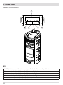
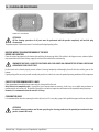
9 - CONTROL PANEL
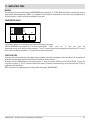
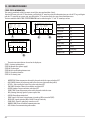
CONTROL PANEL DISPLAY
A
MENU
B
C
D
E
KEY
A - DISPLAY; indicates a series of information on the stove, as well as the identification code of any malfunction.
B - Function selection key indicated by the upper display (i.e. start-up/shutdown)
C - Function selection key indicated by the upper display (i.e. increase/scrolling)
D - Function selection key indicated by the upper display (i.e. decrease/scrolling)
E - Function selection key indicated by the upper display (i.e. menu)
34
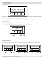
10 - FIRST START-UP
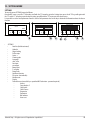
INITIAL START-UP
REV.SOFTWARE
NUM BANCA DATI
At initial start-up, after connecting the power cable and pressing the I/O button, the stove display will show wording for the software
version and database number (after a few seconds it will move on to the next screen).
If the language has already been set, the next screen will be OFF, otherwise one enters the following parameter.
SELECT LANGUAGE
At initial start-up, if it has never been set, the LANGUAGE choice screen appears.
The system displays all possible languages.
Using the arrow keys (C, D) scroll the languages and confirm the desired language using the “E” (OK) key.
LANGUAGE
ITALIANO
ENGLISH
ESPANOL
OK
D
C
E
SETTING TIME AND DAY
The keys that are active for this function: “C”, “D”, “E”. The C-D keys are used to choose time or day while the E key is used to confirm.
OGGI È LUNEDÌ E SONO LE
OGGI È LUNEDÌ E SONO LE
21.25
MODIFICA
GIORNO
C
MODIFICA
ORA
OGGI È LUNEDÌ E SONO LE
21.25
OK
D
21.25
OK
E
C
Technical Dept. - All rights reserved - Reproduction is prohibited
D
OK
E
C
D
E
35
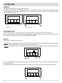
9 - CONTROL PANEL
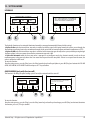
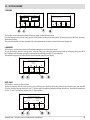
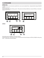
SCREEN OFF
If a LANGUAGE has already been set, the display will go to OFF.
Pressing any one of the keys (B, C, D, E) will result in the first screen showing OFF to be displayed. From this screen, pressing keys "B" and
"E" (respectively corresponding to ON and MENU) it is possible to access the panel or the menu. If no key is pressed, the display will once
again show OFF after 5 seconds.
ECO
OFF
ON
MENU
E
B
OFF-DISPLAY OFF
OFF-DISPLAY ACTIVE
PRELIMINARY OPTIONS
Hydro Air stoves are characterised by the presence of a heating hydraulic circuit and a room air fan for distributing hot air.
The possibility of deviating the hydraulic circuit towards a finned copper exchanger based on user request or automatically to double the
amount of heat distributed to the room air (also see HYDRO AIR SETTINGS MENU).
Room fan
The speed can be set manually or automatically.
In manual mode the speed, from 0 to 5, is chosen by the user from the control panel. The fan is only activated if the air output temperature
exceeds 42°C and is deactivated when it goes below 40°C; while at speed 0 the fan is off.
In automatic the stove adjusts fan speed in order to obtain stable output air temperature (approximately 55°C in Hydro Air On mode and
IMPOSTA VENTILAZIONE
B
ESCI
OK
C
D
E
45°C in Hydro Air Off mode), optimising acoustic comfort with an equal power provided. Even in this case the fan is only activated if air
temperature exceeds 42°C.
For greater comfort, maximum fan speed in automatic mode corresponds to 3 and shuts off only if the temperature falls below 40°C.
IMPOSTA VENTILAZIONE
AUTO
ESCI
B
36
OK
E
9 - CONTROL PANEL
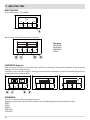
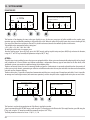
Lighting the stove
To switch on the stove, keep the "B" (ON) key on the panel pressed. The stove starts an ignition procedure that brings the flame to a
suitable level to Supply Power.
OFF
ON
ECO
MENU
B
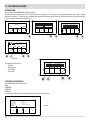
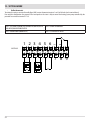
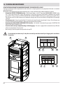
Supplying power
The stove's power supply is signalled by "power level bars": one bar corresponds to minimum power, 5 bars to maximum power, this level
is determined by the heating system heat requirements, the stove adjusts pellet loading parameters, fumes extraction and combustion
air flow to comply with this requirement.
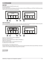
1
10:13
B
TIMER1
25°
23°
AUTO
OFF
TEMP
VENT
C
TOP BAR: active requirements, active programs, power bar, functions
CENTRAL BAR: room temperature, room set, room fan bar
BOTTOM BAR/KEYS: shut-off "B", temperature set modify "C" and fan set "D", menu "E"
1 = power level bars
ECO
MENU
D
E
Technical Dept. - All rights reserved - Reproduction is prohibited
37
11 - MENU STRUCTURE
MENU STRUCTURE
To enter MENU press the "E" key (MENU).
ECO
OFF
ON
MENU
E
Next, this screen with the following functions is displayed:
TEMPERATURE PROGRAMMI
INFORMAZIONI IMPOSTAZIONI
ESCI
B
Sub-menu
TEMPERATURE
PROGRAMMES
INFORMATION
SETTINGS
OK
D
C
E
TEMPERATURE (hydro air)
When accessing this function, the main screen makes it possible to set heating and sanitary water temperature (if boiler with probe
configured - see menu settings input aux).
Select what is to be set and then using the C and D keys increase/decrease the temperature, use the E key to confirm while the B key is
used to exit and return to the main MENU.
TEMPERATURA ACCUMULO
TEMPERATURA
TEMPERATURE
71°
ESCI
B
ESCI
OK
C
PROGRAMMES
D
OK
50°
ESCI
E
In this case it is possible to choose the programme to be set.
Programme selection makes it possible to choose between one of the following options (one choice excludes the other):
TIMER 1
TIMER 2
MANUAL
TEMP. LEVELS
SLEEP FUNCT.
38
OK
11 - MENU STRUCTURE
SELEZIONE PROGRAMMA
TEMPERATURE PROGRAMMI
INFORMAZIONI IMPOSTAZIONI
ESCI
OK
D
C
B
TIMER 1 TIMER 2 MANUALE
LIVELLI TEMP
FUNZ. SLEEP
ATTIVA
ESCI
ENTRA
E
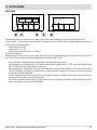
In the MENU screen, move the cursor with arrows "C"-"D" and select PROGRAMS, press ok "E" to confirm. Next select the programme you
wish to set.
Once completed, always press “ACTIVATE” to confirm the choice of programme.
The TIMER 1 and 2 programmes are freely programmable for each 1/2 hour of the day on three different temperature indicators (T1-T2-T3)
and in different ways for each day of the week. The OFF level requires that the stove is switched off in that interval.
TIMER 1
0
LUNEDI’
ESCI
B
T3
TIMER 1
6
12
18
24
0
MARTEDI ‘ MERCOLEDI’
COPIA
OK
D
C
LUNEDI’
6
SALVA
12
10:00
18
24
20°C
6
12
10:00
T2
T1
E
Example of temperature programming for Monday.
Select the TIMER 1 item from the PROGRAM menu and press the ENTRA (ENTER) “E” key, using arrow “D” highlight Monday and press OK
(“E”) to enter programming.
Using the centre arrow keys “C” and “D” select the half hour interval to be selected and use the “E” key to set temperature T1-T2-T3
(depending on whether the key is pressed 1-2-3 times the corresponding temperature can be read in the bottom right of the display).
Once temperature programming for Monday is complete press the "B" SALVA (SAVE) key. If the same temperature scale of Monday is
desired for other week days, after saving ("E" key) press the "C" key (COPIA-COPY), select the day where the program is to be copied using
the "D" key and press the "C" key (INCOLLA-PASTE). Repeat the same procedure until the programmes for all the days of the week are
complete. At this point the stove is programmed according to your temperature needs, which can be modified at any time.
CAUTION:
In order to make stove use easier, MCZ supplies Timer 1 with preset weekly temperatures and times (according to the table below), while
Timer 2 is available. In any case, it is possible to change times and temperatures of Timer 1 at any time.
PANEL OFF DISPLAY FROM TIMER
When timer 1 (for example) has no set temperature, the panel highlights that the stove is in OFF position.
03:33
TIMER 1
16° OFF
OFF
MENU
Technical Dept. - All rights reserved - Reproduction is prohibited
If the stove is off by MANUAL command, the timer will
have no effect.
For the stove to come on with the timer, the panel
must display the image shown on the side; if this
should not be the case, it may be necessary to press
the ON (“B”) key.
39
11 - MENU STRUCTURE
23:00
22:00
21:00
20:00
19:00
18:00
17:00
16:00
15:00
14:00
Time table
13:00
12:00
11:00
10:00
09:00
08:00
07:00
06:00
05:00
04:00
03:00
02:00
01:00
* T1=16°C
40
T2=20°C
T3=22°C
OFF=switched off
T1
OFF
T2
T3
Saturday
T1
OFF
T2
T3
Friday
T1
OFF
T2
T3
Thursday
T1
OFF
T2
T3
Wednesday
T1
OFF
T2
T3
Tuesday
T1
OFF
T2
T3
Monday
T1
OFF
T2
T3
Sunday
Temperatures *
Days
Weekly programmes
00:00
11 - MENU STRUCTURE
MANUAL
This function can be activated from the menu PROGRAMME by pressing the key "C" ACTIVE. When this function is activated the stove no
longer follows time programming of TIMER 1 or 2 programmes, but it keeps the temperature set in the main screen throughout the 24
hour time period. It is possible to switch to programmes at any time.
TEMPERATURE LEVELS
LIVELLI TEMPERATURA
T1
T2
T3
16°
20°
22°
OK
It is possible to change the 3 temperature levels referenced by timers in this menu.
From the PROGRAMS menu use arrow key "D" to move and select T EMP LEVELS, press the "E" keys and enter the
temperature settings screen. With the centre arrow keys "C" and "D" increases/decreases the temperature value, while the "B" is used to
move to the next temperature. With the "E" key (OK) the set values are confirmed.
SLEEP FUNCTION
The sleep is only activated when the stove supplies power and makes it possible to programme a stove shut off time. The shut off can be
delayed for a maximum of 8 hours from current time and with a 10 minute resolution.
To activate, enter the PROGRAM menu, scroll using arrow key "D" up to the Function. SLEEP press the ATTIVA (ACTIVATE) "C" key. In the
next screen, using keys "C" and "D", increase or decrease the minutes (10 minutes each time the key is pressed) and press OK ("E" key) to
confirm the stove shut off time.
NOTE: If the stove is not supplying power the display shows the wording "NOT AVAILABLE".
Technical Dept. - All rights reserved - Reproduction is prohibited
41
12 - INFORMATION MENU
INFORMATION
To enter the menu INFORMATION proceed as follows:
from the main/initial screen, press the "E" Menu button, scroll using the "D" arrow key, up to the Information item, press the "E" ok key,
scroll again using the "D" arrow key up to software/data memory/all.memory/stove state and select the desired item, press OK using the
"E" key to enter the chosen information menu.
ON
MENU
ESCI
OK
E
10:13
B
INFORMAZIONI
TEMPERATURE PROGRAMMI
INFORMAZIONI IMPOSTAZIONI
OFF
TIMER1
25°
23°
AUTO
OFF
TEMP
VENT
D
SOFTWARE
MEMORIA DATI
MEMORIA ALL.
STATO STUFA
ESCI
OK
E
D
ECO
MENU
D
C
E
MAIN SCREEN
INFORMAZIONI
The available information is:
• Software
• Data memory
• All. memory
• Stove state
SOFTWARE INFORMATION
SOFTWARE
MEMORIA DATI
MEMORIA ALL.
STATO STUFA
ESCI
B
OK
C
The available data in this function are:
CODE
FIRMWARE
DATABASE
INTERFACE
It is information that can be used to identify the electronic part of the stove.
INFORMAZIONI-SOFTWARE
CODICE
FIRMWARE
BANCA DATI
PANNELLO
ESCI
42
= MDUO
= 140.7.08.08 [07]
= 000.022
= 14040613A/1000313B
EXAMPLE
D
E
E
12 - INFORMATION MENU
DATA MEMORY-INFORMATION
INFORMAZIONI-MEMORIA DATI
ORE FUNZIONAMENTO = 100
NUMERO ACCENSIONI = 20
DATA COLLAUDO
= 15/01/2013
ESCI
The available data in this function are:
WORKING HOURS
TOTAL IGNITIONS
TEST DATE
ALARM MEMORY-INFORMATION
It gives information about the last alarms detected.
INFORMAZIONI-MEMORIA ALL.
ALLARME 02 - 28/06/13
ALLARME 02 - 21/06/13
ALLARME 02 - 21/06/13
ALLARME 02 - 21/06/13
ESCI
13:44
08:03
08.02
09.46
1
2
3
4
Technical Dept. - All rights reserved - Reproduction is prohibited
43
12 - INFORMATION MENU
STOVE STATE-INFORMATION
This menu is particularly useful if one wants to verify the stove work condition (State).
From the OFF screen, press the "E" Menu button, scroll with the "D" arrow key, up to the Information item, press the ok "E" key, scroll again
with the "D" arrow key up to stove state, press OK with the "E" key and one enters the stove State-information menu.
The items available within STOVE-STATE INFORMATION can be viewed using the "C" and "D" arrow keys and are:
INFORMAZIONI-STATO STUFA
STATO
TEMP.ACQUA
ACTIVE+
VENT.FUMI
ESCI
= 0-OFF
= -43°C
= 471
= 0
INFORMAZIONI-STATO STUFA
COCLEA
TEMP.FUMI
VENT ARIA
VAL.3-VIE
SET = 70°C
SET = 400
SET = 0
ESCI
C
=0
= 30°C
= 0%
= NO HY.
C
INFORMAZIONI-STATO STUFA
MODBUS COM. = OFF
IND.=4
ESCI
SET
REQ
POMP.
CAND.
=0
= BOLL
= OFF
=OFF
state
D
water temp.
set
aux sensor
set
active+
set
fumes fan
set
auger
set
fumes temp.
req
air fan
pump
relay aux
spark plug
modbus com
add.
D
• The main stove states that can be read on the display are:
STATE 1-9 various ignition phases
STATE 20-40 work state (power supply)
STATE 60-79 alarm state
STATE 80-84 shut off/cooling/autoeco state
STATE 85-93 auxiliary functions
STATE 94-95 cleaning state
•
•
•
•
•
•
•
•
•
•
•
•
•
44
WATER TEMP.: Water temperature detected by the probe inside the stove and related SET
AUX SENSOR: detects the value measured by the aux sensor (external/boiler/puffer)
ACTIVE+.: Value read by the Active Plus system and related SET
FAN FUMES: Number of fumes fan revolutions and related SET
AUGER: Number of auger revolutions and related SET
FUMES TEMP: fumes temperature value read by the probe inside the stove
REQ: (Heating/Sanitary) signals if system requires heat
AIR FAN: Room fan operation level
PUMP: signals if the stove's internal pump is turned on (ON) or turned off (OFF)
RELAY AUX: signals activation (ON) or the OFF state of Auxa relay
SPARK PLUG: Signals if spark plug is turned on or off
MODBUS COM: External interface communication state
ADD.: Address for communicating with modbus
13 - SETTINGS MENU
SETTINGS
To enter the menu SETTINGS proceed as follows:
from the OFF screen , press the "E" Menu key, scroll with the "D" arrow key, up to the Settings item, press the ok "E" key, scroll again with
the "D" and/or "C" arrow key up to the chosen setting, press OK with the "E" key to enter the chosen menu.
It is possible to set the listed parameters from this screen. Each parameter has an info key to obtain brief information about the chosen
function.
ON
MENU
ESCI
E
•
IMPOSTAZIONI
TEMPERATURE PROGRAMMI
INFORMAZIONI IMPOSTAZIONI
OFF
AUTOECO
CARICO COCLEA
RICETTA ARIA
ESCI
OK
D
E
B
HYDRO-AIR
RICETTA PLT
CICLO PULIZIA
OK
C
D
E
SETTINGS
•
Auto Eco (default activated)
•
Hydro Air
•
Auger loading
•
Pellet recipe
•
Active +
•
Cleaning cycle
•
Language
•
date - time
•
Aux Input
•
aux output
•
Room Input
•
T. on Pump
•
Pump Pwm
•
Antifreeze function
•
Plt sensor (not available)
•
Modbus com.
•
Display
•
Technical menu (accessible by a specialized MCZ technician - password required)
•
Active +
•
Fume Analysis F
•
Calib.Active
•
Calib.S.fumes
•
Diagnostics
•
Parameters
•
Boll advance
•
Hour reset
Technical Dept. - All rights reserved - Reproduction is prohibited
45
13 - SETTINGS MENU
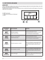
AUTOECO (Factory activated)
IMPOSTAZIONI-AUTOECO
DISATTIVA
AUTOECO
INFO
B
SE ATTIVI L’AUTOECO, LA STUFA SI
SPEGNERA’ QUANDO NON CI SONO
PIU’ RICHIESTE DI CALORE
ATTIVA
AUTOECO
OK
ESCI
D
C
E
B
The Auto eco mode turns the stove off when the heating system does not require heat depending on the menu-settings-input aux
configuration.
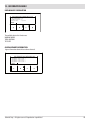
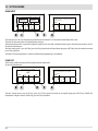
AUTO ECO ACTIVE
The AutoEco active parameter (factory settings) is shown on the top right on the control panel display in the main screen. If heat is not
required, the stove turns off after the set time, switching to Auto Eco (State 84 - it is possible to see Auto eco in the Information Menu,
stove state).
NOTE: With the stove off, if set T is less than T room, or other heat request settings are satisfied the stove does not turn on.
2
1
15:28
B
22°
18°
AUTO
OFF
TEMP
VENT
C
1 = no heat request (T room > T set)
2 = T set
if set temperature is increased > T room (therefore in this
case > 22°C) the stove with start-up after a few seconds due
to the heat request.
ECO
MENU
D
E
AUTO ECO DEACTIVATED
With the stove on, if Auto eco is deactivated and there are no heat requests (different based on menu-settings-aux input settings) the
stove operates at minimum power.
The required condition for restarting is for there to be a heat request for at least 10" consecutively; it is possible to restart if:
• at least 5' have elapsed from when shutdown began
• the TH2O in the stove is < T set H2O
To modify the function:
from the settings menu - using the arrow keys, select the AUTOECO function, press ok (E key) and press D or C key (arrow key) and select:
Activate = to modify the set time from 0 to 30 minutes (factory default 5 minutes)
Deactivate = to deactivate Auto Eco
46
13 - SETTINGS MENU
HYDRO AIR
IMPOSTAZIONI-HYDRO-AIR
HYD-AIR
AUTO
HYD-AIR
ON
INFO
B
ON = MAX POTENZA ALL’AMBIENTE
OFF=MAX POTENZA ALL’IMPIANTO
AUTO=GESTIONE AUTOMATICA
HYD-AIR
OFF
OK
ESCI
D
C
E
B
The Hydro Air function can be activated/deactivated manually or managed automatically (factory default setting).
In Hydro-Air On mode the internal three-way valve is switched so that the water, before going towards the system, passes through the
front radiator, transferring heat to the environment through the fan up to 6 kW (at maximum power with water temperature at 70°C).
In Hydro-Air Off mode the internal three-way valve is switched so that stove water goes directly to the system, without passing through
the front radiator. In this case power released to the environment may reach 3 kW.
In Hydro-Air Automatic mode the three-way valve is managed in an intelligent way by the electronic control in order to release
maximum power to the room only when there is an actual heat request from the stove probe. If there is no request from the room, the
valve is switched as in OFF mode.
To enter the function:
from the settings menu - press ok (E key), press the D key (arrow key) and scroll up to Hydro-air, press OK (E key) and activate the HYD-AIR
AUTO / HYD-AIR ON / HYD-AIR OFF function and press ok "E" key to confirm.
AUGER LOADING (only with the stove off)
This function is for filling the pellet loading system. Can only be activated with the stove off.
IMPOSTAZIONI-CARICO COCLEA
DISATTIVA
CARICO
INFO
B
C
USA IL “CARICO COCLEA” QUANDO LA
COCLEAE’ RIMASTA VUOTA E LA DEVI
CARICARE VELOCEMENTE
ATTIVA
CARICO
OK
D
ESCI
E
B
To enter the function:
from the settings menu - press ok (E key), press the D key (arrow key) and scroll up to load auger, press OK (E key) and activate/deactivate
the function, press ok ("E" key) to confirm.
Technical Dept. - All rights reserved - Reproduction is prohibited
47
13 - SETTINGS MENU
PELLET RECIPE
IMPOSTAZIONI-RICETTA PLT
VARIA PERCENTUALMENTE LA VELOCITA’
DELLA COCLEA PER ADATTARE LA STUFA
AL TIPO DI PELLET
+15%
INFO
B
OK
ESCI
D
C
E
B
This function is for adapting the stove to the type of pellet in use. As there are many types of pellet available on the market, stove
operation can vary considerably according to the quality of the fuel. When the pellets clog up the brazier due to excess loading of fuel,
vice-versa if the flame has a tendency to shut-off, it is possible to decrease/increase the amount of pellets in the brazier:
The available values compared to factory settings are:
+15% +10% + 5%; 0%; -10% -20% -30%
To modify the pellet recipe, in sequence, press:
from the Settings menu- press ok (E key), press the D KEY (arrow) scroll up to pellet recipe and press OK (E key) and enter the function,
using the "C" and "D" keys to modify the parameter and press Ok ("E" key).
ACTIVE +
The pellet type is not a problem because the stoves are equipped with the Active system and automatically adapt to pellet of any length
with a diameter of 6-8 mm. Effective and efficient combustion is independent from any type of connection to the flue which, with
traditional systems, may constitute a problem during the installation phase.
Thanks to an internal sensor, the stove is extremely reliable and precise. Combustion air is constantly adjusted based on the quantity of
pellets present in the brazier, guaranteeing an effective and efficient combustion this way that translates into decreased consumption,
emissions and less frequent cleaning.
Thanks to Active plus, it is possible to control and communicate with the stove, even by way of Smartphone and tablet. Since it is possible
to manage more evolved gear motors (with continuous operation), and the new pellet stoves equipped with active plus are more silent.
IMPOSTAZIONI-ASPIRAT.
CORREGGI LA PORTATA
DELL’ARIA COMBURENTE
0%
INFO
B
OK
D
ESCI
E
B
This function is used to adjust combustion air if the flame is too high or too low.
It can be activated from the SETTINGS menu, scroll using the “D” arrow key up to the “Ricetta Aria” (Air recipe) function, press OK using the
“E” key, and, using the “D” arrow key modify the parameter and press “ok”“E” key.
The fixed parameters that can be set are: +10; +5; -5; -10
48
13 - SETTINGS MENU
CLEANING
IMPOSTAZIONI-CICLO PULIZIA
DISATTIVA
CICLO PUL.
INFO
B
ATTIVA SUBITO UN CICLO DI
PULIZIA DEL BRACIERE
ATTIVA
CICLO PUL.
OK
ESCI
E
C
B
This function can only be activated while the power supply is in the following mode:
from the Settings menu- press ok (E key), press the D key (arrow), scroll up to the “ciclo pulizia” (cleaning cycle) press OK (E key)- Activates/
deactivates cleaning.
This procedure activates the fume extraction fan at the maximum level in order to clean the brazier and expel soot.
LANGUAGE
This function is used to choose the desired language among those set in the control panel.
To enter the function, from the Settings menu - press ok (E key), press the D key (arrow key) and scroll up to language item, press OK (E
key) and choose the language among the various ones set and finally press Ok ("E" key) to confirm.
The available languages are: Italian/English/French/German/Spanish/Dutch/Danish
IMPOSTAZIONI-LINGUA
ITALIANO
ENGLISH
FRANCAIS
OK
D
C
B
E
DATE-TIME
This function is used to set date and time.
To enter the function, from the Settings menu - press ok (E key), press the D key (arrow key) and scroll up to the date-time item, press OK
(E key) to enter the function. Next, press the "E" (ok) key again to modify day/month/year/hour and minutes. To modify the parameters,
use the “C” and “D” (arrow) keys and press the "E" key to confirm.
IMPOSTAZIONI-DATA-ORA
OGGI E’ LUNEDI’
E SONO LE
ESCI
B
24/06/13
14:14
OK
C
D
Technical Dept. - All rights reserved - Reproduction is prohibited
E
49
13 - SETTINGS MENU
AUX INPUT (using one of the following parameters excludes the other)
The auxiliary input allows choosing the system configuration type based on which the stove is connected.
To enter the function press:
from the Settings menu- press ok (E key), press the D (arrow) key and scroll up to the Aux Input item and press OK (E key). Using the “C”
and “D” keys select the desired heating system type and press ok with the “E” key.
IMPOSTAZIONI-INGRESSO AUX
TERMOST AMB 2
SONDA ESTERNA
SONDA BOLLIT.
TERMOST BOLL.
SONDA PUFFER
TERM. PUFFER
INFO
B
C
OK
D
E
It is possible to connect the following to the auxiliary input:
Room thermostat 2
External probe
Boiler probe
Boiler thermostat
Puffer probe
Puffer Thermostat
Note: The boiler probe/thermostat choice implies the three-way aux output designation.
The puffer probe/thermostat choice implies the pump aux output designation.
• Room Therm.2
The stove heat request may take place from any part of the room probe or from the “Termostato Amb 2” (Room thermostat 2) installed
in a room that is different from the one where the stove is positioned and is connected to terminals 1 and 2 of the back terminal board.
Contact closing the terminal kicks off the heat request.
Notes: Installation of this thermostat is optional, the stove can also operate without it. Since the contact is N.O., the room probe is the
only heat request command.
Possible active weekly programming does not act on Room Thermostat 2 but rather on the probe on board the stove.
50
13 - SETTINGS MENU
• External probe
It makes it possible to work with system temperature adjustment. If installing an external probe on terminals 1 and 2 (NTC 10KOhm at
25°C b=3435) water temperature is automatically calculated by the electronics based on the external temperature according to the curves
shown below.
The external probe must be installed on an external wall exposed towards North or North-West. If necessary, it is possible to correct the
value read by the probe of + 5 -5°C.
• Boiler probe
To activate this option, connect a probe (NTC 10KOhm at 25°C b=3435) to points 1 and 2 of the back 9 pole terminal board.
The heat request occurs when the boiler probe reads a temperature that is 2°C below the one set by the accumulation temperature marked
by a tap in the temperature menu.
In this configuration the aux output is configured as a potential free contact to control the 3-way valve (contact 7-8-9 of the back 9 pole
terminal board)
• Boiler thermostat
To activate this option, connect a Normally Open (N.O.) contact thermostat to points 1 and 2 of the back 9 pole terminal board.
The heat request occurs when boiler thermostat closes the contact.
Even with this configuration the Aux output is configured as a potential free contact to control the 3-way valve (contact 7-8-9 of the back
9 pole terminal board).
• Puffer probe
To activate this option, connect a probe (NTC 10KOhm at 25°C b=3435) to points 1 and 2 of the back 9 pole terminal board.
The heat request occurs when the boiler probe reads a temperature that is 2°C below the one set by the accumulation temperature marked
by a radiator in the temperature menu.
During the installation with puffer, stove operation is only and exclusively determined by the puffer probe and not by the room probe. The
purpose of the room probe on the stove is only to control the heating system pump controlled by the potential free contact N.O.: (max 5
ampere, not suitable for brushless pumps with upper start-up current) on terminals 8-9.
Example of operation with Hydro Air On or Auto:
• if the puffer is satisfied but the room probe is not, with eco stop active the stove shuts off (continuing to disburse heat through the
room fan up until shut-off)
• if the puffer is satisfied but the room probe is not, with eco stop deactivated, the stove remains on at minimum power. In this case
hot water from the puffer is used through the pump to heat the front radiator
• if the puffer calls for heat and the room probe does not, the fan behaves based on “Hydro Air” and “Ventilatore” (Fan) settings.
Technical Dept. - All rights reserved - Reproduction is prohibited
51
13 - SETTINGS MENU
• Puffer thermostat
To activate this option, connect a Normally Open (N.O.) contact thermostat to points 1 and 2 of the back 9 pole terminal board.
Even with this configuration the purpose of the room probe on the stove is only to control the heating system pump controlled by the
potential free contact on terminals 7-8-9.
POS.1-2 EXTERNAL THERMOSTAT/THERMOSTAT/BOILER/PUFFER
(AUX INPUT) BOILER PROBE/PUFFER
POS.5-6 HOME AUTOMATION
POS.3-4 ROOM PROBE (ROOM INPUT)
POS.7-8-9 AUX OUTPUT RELAY
1 2 3 4 5 6
NC
NO
C
INPUT AUX
7 8 9
52
13 - SETTINGS MENU
HYDRO AIR STOVE PRINCIPLE DIAGRAMS
The following diagrams are to be used only as a guideline. For proper connection, always follow the notes for
the plumbing and heating installer. The plumbing system must meet local, regional or national requirements.
Installation and verification of operation is to be performed only by specialized, authorized personnel. The
manufacturer will not be held liable for noncompliance with the provisions listed above.
HEATING ONLY CONFIGURATION
BOILER CONFIGURATION
POS.1-2 = BOILER
PROBE/THERMOSTAT
1 2 3 4 5 6
NC
NO
C
7 8 9
Technical Dept. - All rights reserved - Reproduction is prohibited
53
13 - SETTINGS MENU
HYDRO STOVE WITH PUFFER CONFIGURATION
1 2 3 4 5 6
POS.1-2 =
THERMOSTAT
54
PUFFER
NC
NO
C
PROBE/
7 8 9
13 - SETTINGS MENU
OUTPUT AUX
IMPOSTAZIONI-USCITA AUX
ALLARME
REMOTO
INFO
B
C
CALDAIA
AUX
IMPOSTA L’INGRESSO AMBIENTE:
SONDA O TERMOSTATO.
MORSETTI 3-4
USCITA
IN TEMP
OK
D
ESCI
E
B
The AUX output makes it possible to use a relay contact, based on the system configuration type chosen in the Aux Input menu.
It acts on contact 7-8-9 of the external terminal board. The functions can only be selected if boiler or puffer configuration has not been
chosen in the Aux Input menu and are:
• Remote alarm (9-8=C-NO)
• Auxiliary boiler (9-7=C-NC)
• Auxiliary output in temperature (9-8-7=C-NO-NC)
To enter the function press:
from the Settings menu- press ok (E key), press the D (arrow) key and scroll up to the Aux Output item and press OK (E key). Using the “C”
and “D” keys to select the Remote Alarm(Aux boiler/Output in temp and press OK ("E" key).
•
•
•
•
•
If the Aux output is set on Remote Alarm, the NO contact is closed when an alarm is present.
If the Aux output is set to Auxiliary Boiler, the NC contact remains closed in all alarm states, in = "OFF" state, in 80 “Shutdown” state
and in 51 “COOL” state. Under all conditions it remains open.
Output at temperature: the NO contact closes when Boiler temperature exceeds the value set by the user. It can be set from 30 to 60,
it is used, for example, to disconnect the aux boiler above a certain temperature (using the NC contact) or to start an external pump
at temperature (using the NO contact)
If the boiler configuration has been chosen, the Aux contact is fixed at “Valvola tre vie bollitore” (Three-way boiler valve): the contact
switches when a heat request is received from the boiler.
If the Puffer configuration has been chosen, the Aux contact is fixed at “Comando pompa” (Pump Control): the NO contact closes
when a heat request is received from the Room PROBE
Technical Dept. - All rights reserved - Reproduction is prohibited
55
13 - SETTINGS MENU
ROOM INPUT
IMPOSTAZIONI-INGRESSO AMB
SONDA
AMBIENTE
INFO
OK
D
C
B
IMPOSTA L’INGRESSO AMBIENTE:
COME SONDA O COME TERMOSTATO.
(MORSETTI 3-4)
TERMOSTATO
AMBIENTE
ESCI
E
B
The room input is used to set the probe or the thermostat at terminals 3-4 of the back terminal board of the stove.
The stove has the room probe set as default factory settings.
Selecting the thermostat it is possible to replace the probe on the stove with a thermostat that requests heat when the contact is closed.
To enter the function press:
from the settings menu - press ok (E key), press the D key (arrow) and scroll up to Room Input, press OK (E key) and select room thermostat,
press E key to confirm.
Attention!!! If room temperature is selected, weekly hourly programming is not available.
PUMP ON T
This function enables adjustment of the pump activation temperature.
To enter the function press:
IMPOSTAZIONI-T ON POMPA
TEMPERATURA MINIMA DELL’ACQUA
PER LA PARTENZA DELLA POMPA
DI CALDAIA
60°
INFO
B
C
OK
D
ESCI
E
B
from the Settings menu- press ok (E key), press the C-D key (arrow) and scroll up to temp.On pump, press OK (E key)- Modify the
temperature using the central C and D keys, press the E key to confirm.
56
13 - SETTINGS MENU
PWM PUMP
This function is used to set high efficiency pump speed.
To enter the function press:
from the Settings menu- press ok (E key), press the C-D key (arrow) and scroll up to PWM Pump, press OK (E key)- Modify the percentage
using the central C and D keys, press the E key to confirm.
IMPOSTAZIONI-POMPA PWM
IMPOSTA LA VELOCITA’
DELLA POMPA PWM AD
ALTA EFFICIENZA
AUTO
INFO
B
OK
D
C
ESCI
E
B
FUNCT. ANTI-FREEZE
It consists of activating the pump (level 1) or the stove (level 2) and is automatically activated by the temperature read by the stove probe
and the temperature read by the external probe (if present and connected to the aux input).
IMPOSTAZIONI-FUNZ ANTIGELO
DISATTIVA
FUNZ ANTI.
INFO
B
C
IMPOSTA LA TEMPERATURA
DI ATTIVAZIONE DELLA FUNZIONE
ANTIGELO
ATTIVA
FUNZ ANTI.
OK
D
ESCI
E
B
The level 1 anti-freeze activation conditions (PUMP ON) are:
boiler temp < anti-freeze set +3°C
The level 2 anti-freeze activation conditions (PUMP and FLAME ON) are:
boiler temp = anti-freeze set
Anti-freeze activation conditions on external probe (if present) are:
ext_filtered temp < anti-freeze set -3℃
To enter the function, press and adjust anti-freeze set:
from the Settings menu- press ok (E key), press the C-D key (arrow) and scroll up to Antifreeze function and press OK (E key)- Activate and
set (from 1 to 5°C) or deactivate the function and press the E key to confirm.
PELLET SENSOR
Optional Function.
Technical Dept. - All rights reserved - Reproduction is prohibited
57
13 - SETTINGS MENU
MODBUS COM.
Is a communication system that makes it possible for the stove to receive commands from a Smartphone/tablet through a Web/Wi-fi
interface.
To enter the function press:
from the settings menu - press ok (E key), press the C-D key (arrow) and scroll up to Modbus com. and press OK (E key)- Set the address
and press E key to confirm.
IMPOSTAZIONI-MODBUS COM.
INFO
B
IMPOSTA L’INDIRIZZO MODBUS SLAVE
BAUD RATE 19.200 1 STOP BIT EVEN PARITY - 19200 8N1
3
INDIRIZZO
OK
D
C
ESCI
E
B
DISPLAY
IMPOSTAZIONI-DISPLAY
CONTRASTO
LUMINOSITA’
OK
B
C
D
E
Adjust display contrast and brightness. This function is found in:
from the Settings menu- press ok (E key), press the C-D key (arrow) and scroll up to Display, press OK (E key)- Modify the settings using
the B - C - D keys and press the E key to confirm.
58
14 - TECHNICAL MENU
TECHNICAL MENU
To access the technical menu you must contact the assistance centre as it requires a password.
To make changes in the technical menu, enter the SETTINGS menu, press the "E" (OK) key, scroll using the “C”-”D” arrows and select
Technical menu and press OK (E key)- Enter the password and press the E key to confirm.
IMPOSTAZIONI-MENU TECNICO
DIGITA PASSWORD
0000
ESCI
B
C
OK
D
E
To enter the password:
using the C and D keys, set the numbers (1-2-3....9) with the E (OK) key and move on to the next digit, once the four digits have been
entered, press the E key to enter the technical menu.
The technical menu displays the following parameters:
• ACTIVE +
• FUMES ANALYSIS F.
• CALIB.ACTIVE
• CALIB.S.FUMES
• DIAGNOSTIC
• PARAMETERS
• BOLL ADVANCE
• RESET HOURS
Technical Dept. - All rights reserved - Reproduction is prohibited
59
15 - SAFETY DEVICES AND ALARMS
SAFETY DEVICES
The product is fitted with the following safety devices
ACTIVE +
Besides adjusting the stove operation, it also guarantees that the pellet loading auger is blocked if unloading or there is significant back
pressure.
SMOKE TEMPERATURE PROBE
Detects the temperature of the smoke, thereby enabling start-up or stopping the product when the temperature drops
below the preset value.
CONTACT THERMOSTAT IN THE FUEL HOPPER
If the temperature exceeds the preset safety level, it immediately shuts down the running of the stove.
WATER THERMOSTAT
If the temperature exceeds the preset safety level, it immediately shuts down the running of the stove.
WATER TEMPERATURE SENSOR
When the water reaches the stop temperature (85°C) the probe automatically instructs the boiler to carry out
automatic "OFF Stand-by" shut-off.
ELECTRICAL SAFETY
The stove is protected against violent changes in current by a general fuse located in the control panel at the back of the
stove. Other fuses that protect the circuit boards are located on the latter.
SMOKE FAN
If the fan stops, the electronic board shuts off the supply of pellets in good time, and an alarm message is displayed.
GEAR MOTOR
If the reduction motor stops, the stove will continue to run until the flame goes out due to lack of fuel and until
a minimum level of cooling is reached.
TEMPORARY POWER CUT
When a power cut is less than 10" the stove returns to its previous operating state; if it is more, it executes a
cooling/re-ignition cycle.
FAILED START-UP
If during ignition no flame develops, the stove will go into alarm condition.
ANTI-FREEZE FUNCTION
If the probe in the boiler detects a water temperature of less than 5°C, the circulation pump is automatically activated to keep the system
from freezing.
PUMP ANTI-SEIZURE FUNCTION
If the pump is not used for prolonged periods, it is activated periodically for a few seconds to keep it from
seizing up.
60
15 - SAFETY DEVICES AND ALARMS
TAMPERING WITH THE SAFETY DEVICES IS PROHIBITED
If the stove is NOT used as described in this instruction booklet, the manufacturer refuses to accept any responsibility
for damage to persons and property that may arise. The manufacturer furthermore refuses to accept responsibility
for damage to persons and property arising from the failure to observe all the rules contained in the manual and
in particular:
• All the necessary measures and/or precautions must be adopted when performing maintenance, cleaning and
repairs.
• Do not tamper with the safety devices.
• Do not remove the safety devices.
• Connect the stove to an efficient smoke extraction system.
• First, check that the environment where it is to be installed is properly ventilated.
Only after eliminating the cause of the intervention of the safety system is it possible to re-ignite the stove and thus
restore its automatic operation. This manual will help you understand which anomaly has occurred, and explain
how to intervene according to the alarm message displayed on the stove.
Technical Dept. - All rights reserved - Reproduction is prohibited
61
15 - SAFETY DEVICES AND ALARMS
ALARM ALERTS
If there is an operational anomaly, the stove enters the alarm phase displaying the problem that has taken place through a code, a brief
description of the alarm type and an acoustic warning.
The following table describes the possible alarms indicated by the stove, associated to the respective code that appears on the panel and
helpful tips to solve the problem.
A05
B = RESET (cancels alarm)
C = INFO (provides information on the alarm type)
E = MENU
RESET
B
WRITTEN ON THE
DISPLAY
INFO
C
MENU
E
TYPE OF PROBLEM
SOLUTION
The fire does not ignite.
(without acoustic alarm)
Check the level of pellets in the tank.
Check that the brazier rests correctly in its seat and
has no visible deposits of unburned pellets.
A02
NO FLAME
The fire goes out abnormally.
(without acoustic alarm)
Check the level of pellets in the tank.
Check that the brazier rests correctly in its seat and
has no visible deposits of unburned pellets.
A03
PLT SAFETY
Pellet tank temperature is too high
A04
FUME TEMP
Fume temperature is too high
A01
NO IGNITION
A05
OBSTRUCTION
62
OSTRUZIONE CANNA
FUMARIA
Chimney flue clogged
Wait for the cooling phase to end, cancel the alarm
and reduce pellet loading (SETTINGS MENU - Pellet
recipe). If the alarm persists, contact the service
centre.
Wait for the cooling phase to end, cancel the alarm
and reduce pellet loading (SETTINGS MENU - Pellet
recipe). If the alarm persists, contact the service
centre.
Verify brazier clogging, smoke duct, lower
compartment and door closing. If the alarm persists,
contact the service centre.
15 - SAFETY DEVICES AND ALARMS
WRITTEN ON THE
DISPLAY
TYPE OF PROBLEM
SOLUTION
A08
Faulty smoke fan.
Check that the lower compartment is clean (see
dedicated stove cleaning pages) and verify that it is
not obstructed, is clean and cancel the alarm.
If the alarm persists, contact the service centre.
A09
Smoke sensor fault.
Contact an authorised service centre to have the
component replaced and, if needed, replace the
component.
Auger gear reducer fault.
The component is not working regularly.
Contact an authorised service centre to have the
component replaced and, if needed, replace the
component.
Electronic board overheating
Wait for the cooling phase to end, cancel the alarm
and reduce pellet loading (SETTINGS MENU - Pellet
recipe). If the alarm persists, contact the service
centre. .
Active sensor anomaly
Active Plus sensor operation anomaly. Contact an
authorised service centre to have the component
replaced and, if needed, replace the component.
Water thermostat intervention
Water temperature is too high or thermostat
operational anomaly. If the alarm persists, contact the
service centre.
Fault with water sensor
Possible fault in the safety component. Contact an
authorised service centre to have the component
replaced and, if needed, replace the component.
Auxiliary probe fault
Possible component fault.
Check that the probe inserted in the system respects
the characteristics specified in the instructions (see
external probe).
Contact an authorised service centre to have the
component replaced and, if needed, replace the
component.
FLUE GAS FAN
SMOKE TEMPERATURE PROBE
A11
GEAR REDUCER
A13
BOARD TEMP
A14
ACTIVE SENSOR
A18
WATER SIC
A19
WATER PROBE
A20
AUX PROBE
Exiting the alarm conditions
When the stove enters an alarm state, an automatic cooling/shut-off phase begins, at the end of which the cause of the alarm is displayed
on the small panel.
Before resetting the alarm, follow the controls indicated in the previous table, and then press the RESET key for a few seconds (or remove
power to the stove using the main ON/OFF switch on the back of the stove).
If the indicated actions do not resolve the problem, the alarm condition will occur once again with different timing based on the alarm
type: in this case, contact technical assistance.
Technical Dept. - All rights reserved - Reproduction is prohibited
63
15 - SAFETY DEVICES AND ALARMS
SHUT DOWN
If the shut down key is pressed or one of the following conditions occurs:
• power request ends (Power = 0) for Ecostop, Timer, Sleep
• an alarm condition occurs
• water overheating occurs
the stove enters the shut down and thermal cooling phase that includes automatically executing the following phases:
• pellet loading stops
• the room fan maintains the set speed until it cools down
• the fumes extractor is activated at maximum speed and remains on for a fixed period of 5 minutes, at the end of which the stove off
temperature is reached.
During the shut down phase the small panel displays the wording OFF (see screen) but if it is in shut down due to an alarm condition, the
small panel displays the related code (See alarms table)
OFF
ON
B
ECO
MENU
E
BLACKOUT WITH STOVE ON
If power is lost for less than 10" from stove start-up, it is repositioned in the phase where it was before the power failure.
If the loss of power exceeds 10", when the stove is powered once again, it goes back to the previous operational condition with the
following procedure it
• carries out a cooling phase, during which the panel displays OFF BLACKOUT
• restarts the stove
If the stove is in ignition phase when the blackout occurs, it will not turn back on once the power is restored (there is a risk that residual
pellets are present in the brazier) and the panel will display OFF BLACK-OUT.
If the ON key is pressed during the cooling phase, the stove stops executing the blackout restore state and it proceeds with ignition as
requested by the command. In the same way, pressing OFF is interpreted as a shut off command.
64
16 - CLEANING AND MAINTENANCE
EXAMPLE OF A CLEAN BRAZIER
EXAMPLE OF A DIRTY BRAZIER
ATTENTION!
All the cleaning operations of all parts must be performed with the product completely cold and the plug
disconnected.
The product requires little maintenance if used with certified good quality pellets.
DAILY OR WEEKLY CLEANING PERFORMED BY THE USER
BEFORE EACH IGNITION
Clean the ash and any deposits in the brazier that could clog the air passage holes. If the pellets in the hopper run out, unburned pellets
may accumulate in the brazier. Always empty the residue in the brazier before each start-up.
REMEMBER THAT ONLY A CORRECTLY POSITIONED AND CLEAN GRATE CAN GUARANTEE THE OPTIMAL LIGHTING AND
OPERATION OF YOUR PELLET STOVE.
For the brazier to be cleaned properly, remove it from its housing completely and thoroughly clean all the holes and the grate on the
bottom.
If good quality pellets are used, you will normally only need to use a brush to restore the optimal operating conditions of the component.
CHECKS TO BE PERFORMED EVERY 2/3 DAYS
Clean compartment around brazier to remove any ash, being careful of hot ash.
Only if the ash is completely cold, is it possible to use a vacuum cleaner to remove it. In this case, use a suitable vacuum cleaner to
remove particles of a certain size. The quality of the pellets used and user experience will determine the required cleaning frequency.
However, it is recommended not to exceed 2 or 3 days.
CLEANING THE GLASS
It is recommended to clean the ceramic glass with a dry brush, or if it is very dirty, spray a little specific detergent and clean with a cloth.
ATTENTION!
Do not use abrasive products and do not spray the glass cleaning product on the painted parts and on the door
gaskets (ceramic fibre cord).
Technical Dept. - All rights reserved - Reproduction is prohibited
65
16 - CLEANING AND MAINTENANCE
CLEAN THE EXCHANGER AND THE COMPARTMENT BENEATH THE BRAZIER EVERY 2/3 DAYS
Cleaning the exchanger and the compartment beneath the brazier is a simple operation but very important if the boiler is to maintain
optimal performance.
We therefore recommend cleaning the internal exchanger every 2-3 days, performing these simple operations in sequence:
• Activate the “PULIZIA” (CLEANING) function – with the stove on press - menu (“E” key), select “IMPOSTAZIONI” (SETTINGS) using
the “C” and “D” key and press OK (“E” key), scroll using the “C” and “D” keys and select “CICLO PULIZIA” (CLEANING CYCLE), confirm
pressing “OK” (“E” key), activate the “ATTIVA CICLO DI PULIZIA” (ACTIVATE CLEANING CYCLE) function, confirm by pressing OK (“E” key).
This procedure starts the smoke extractor on the maximum setting to expel the soot that becomes dislodged when the exchanger
is cleaned.
• Clean the pipe unit - Using the provided hook ”A”, shake the rods located beneath the top firmly 5-6 times. This will remove any
soot that has deposited on the exchanger's smoke ducts during normal stove operation.
• Deactivate the “CICLO PULIZIA” (CLEANING CYCLE) function – this function is deactivated by pressing the “DISATTIVA CICLO
PULIZIA” (DEACTIVATE CLEANING CYCLE).
• Clean the smoke conveyor compartment (fig. in following page) - The stove is equipped with a removable ash tray “G” which
collects any accumulations of soot and ash.
• Once cleaning is finished reposition the top and the ash tray“G”.
If such cleaning is not done every 2-3 days the stove could go into alarm caused by ash clogging after several hours
of operation.
A
A
TEMPERATURE PROGRAMMI
INFORMAZIONI IMPOSTAZIONI
ESCI
OK
D
C
B
E
IMPOSTAZIONI
AUTOECO
CARICO COCLEA
RICETTA ARIA
ESCI
B
66
HYDRO-AIR
RICETTA PLT
CICLO PULIZIA
OK
C
D
E
16 - CLEANING AND MAINTENANCE
CLEANING THE LOWER COMPARTMENT
Clean around the brazier “C”. Remove the tray “D” and the brazier “C”. Loosen the screws and remove the fumes plug “E” and using the
nozzle of a vacuum cleaner, remove any ash and soot that may have built up in the lower exchanger indicated by the arrow.
Before putting the cap “E” back, changing gasket “F” is recommended
Before removing ash using a vacuum cleaner, it is recommended to clean the internal walls of the stove using the supplied scraper.
SCRAPER
B
D
F
E
C
LOWER COMPARTMENT
CLEANING
G
Technical Dept. - All rights reserved - Reproduction is prohibited
67
16 - CLEANING AND MAINTENANCE
PERIODIC CLEANING PERFORMED BY A QUALIFIED TECHNICIAN
CLEANING THE EXCHANGER AND PIPE UNIT
In order to clean the exchanger and the pipe unit, while the stove is cold, proceed in the following manner:
1
2
2
3
5
8
3
5
6
8
12
11
8
7
15
16 14
9
8
11
15
12
14
13
17
1
16
18
4
1
1
10
68
16 - CLEANING AND MAINTENANCE
•
•
•
Remove the top “1”
Remove the 4 screws “2”
Remove the two profile supports “3”
To avoid removing the entire cladding, block the two front profiles with two clamps “4”.
• Remove the four screws “5” and as a result remove the two plates of the turbulator rods “6”
• Loosen the two screws “7”, remove the two screws “8” and remove the entire fan block “9”
• Remove the exchanger “10”
• Loosen the two screws “11”, remove the two screws “12” and remove the exchanger support “13”
• Loosen the two screws “14” and remove the rods “15”
• Remove the two screws with shims “16” and the stove cover “17”
• Remove the turbulators “18”
At this point, using a rod or a brush for cleaning bottles, clean inside the pipe unit and the pipes, removing any ash deposits.
Check the cover seal “17” and replace it if necessary.
CAUTION: the exchanger must be cleaned at the end of the season by an authorised and qualified technician so that
any worn seals may be replaced.
CLEANING THE SMOKE DUCT AND GENERAL CHECKS
Clean the smoke extractor duct, especially around the “T” joints, bends and any horizontal sections.
For information on cleaning the flue, contact a chimney sweep.
Check the seal of the ceramic fibre gaskets on the door of the stove. If necessary, order new replacement gaskets from the retailer or
contact an authorised service centre to carry out the operation.
CAUTION:
The frequency with which the smoke outlet system is cleaned depends on the use of the boiler and the type of
installation.
We recommend relying on an authorised service centre for end-of-season cleaning and maintenance, as they will
carry out all of the previously mentioned work and inspect the stove components.
SHUTDOWN (end of season)
At the end of each season, before switching the product off, it is recommended to remove all the pellets from the hopper with a vacuum
cleaner with a long pipe.
When not in use the appliance must be disconnected from the mains power supply. It is recommended to remove the
power cable for additional safety, especially in the presence of children.
The service fuse may have to be replaced if the control panel display does not switch on when the product is switched on again by pressing
the main switch on its side.
There is a fuse compartment on the back of the product, under the power socket. After having disconnected the plug from the socket, use
a screwdriver to open the cover of the fuse compartment and if necessary, replace them (3.15 A delayed).
Technical Dept. - All rights reserved - Reproduction is prohibited
69
16 - CLEANING AND MAINTENANCE
CHECKING THE INTERNAL COMPONENTS
ATTENTION!
The internal electromechanical components must only be checked by qualified personnel whose technical expertise
includes combustion and electricity.
We recommend that an annual maintenance service is carried out (with a scheduled service contract). This service is essentially a visual
and functional inspection of the internal components. The following is a summary of the checks and/or maintenance that are essential
for the correct operation of the product.
PARTS/INTERVAL
1 DAY
Brazier
Ash pan
·
Glass
Lower compartment
Complete exchanger
Smoke duct
Door gasket
2-3 DAYS
·
7 DAYS
30 DAYS
60-90 DAYS
1 YEAR
·
·
·
Internal parts
Flue
Circulation pump
A plate heat exchanger
Plumbing components
Electro-mechanical components
·
·
·
·
·
·
·
·
CLEANING THE CONTROL PANEL DISPLAY
ATTENTION!!
THE PANEL DISPLAY IS VERY DELICATE, IT IS SUPPLIED WITH A PROTECTIVE FILM.
RECOMMENDATIONS FOR CLEANING:
Clean using a soft cotton cloth, dry or slightly moist.
Do not use aggressive detergents or polyester materials.
Do not use abrasive sponges or powder detergents nor solvents such as alcohol and petrol, since they may damage the surface of the
device.
70
17-FAULTS/CAUSES/SOLUTIONS
CAUTION:
All repairs must be carried out exclusively by a specialised technician, with the stove completely cold and the electric
plug pulled out.
ANOMALY
POSSIBLE CAUSES
The pellets are not fed into the combustion The pellet hopper is empty
chamber.
Sawdust has blocked the feed screw
SOLUTIONS
Fill the hopper with pellets
Empty the hopper and remove the sawdust
from the feed screw by hand
Faulty gear motor
Replace the gear motor
Faulty electronic board
Replace the circuit board
The fire goes out or the stove stops The pellet hopper is empty
automatically
The pellets are not fed
Fill the hopper with pellets
See the previous anomaly
The pellet temperature safety probe has Let the stove cool down, reset the
been triggered
thermostat until the problem is
resolved and switch the stove back on.
If the problem persists contact Technical
Assistance.
Chrono active
Check if the chrono setting is active
The door is not closed properly or the Close the door and replace the gaskets
gaskets are worn
with original ones
Unsuitable pellets
Change the type of pellets with those
recommended by the manufacturer
Low pellet supply
Check the flow of fuel following the
instructions in the booklet.
The combustion chamber is dirty
Clean the combustion chamber, following
instructions in the manual
Clogged outlet
Clean the smoke duct
Faulty smoke extraction motor
Check the motor and replace it, if necessary
Water tank temperature too high
Check correct operation of the water
circulation pump and the hydraulic system
in general.
Technical Dept. - All rights reserved - Reproduction is prohibited
71
17-FAULTS/CAUSES/SOLUTIONS
ANOMALY
POSSIBLE CAUSES
The stove runs for a few minutes and then Start-up phase is not completed
goes out
Temporary power cut
Clogged smoke duct
SOLUTIONS
Repeat start-up
Wait for the automatic restart
Clean the smoke duct
Faulty or malfunctioning temperature Check and replace the probes
probes
Pellets accumulate in the brazier, the glass Insufficient combustion air
of the door gets dirty and the flame is
weak
Damp or unsuitable pellets
Change the type of pellets
Faulty smoke evacuation motor
Check the motor and replace it, if necessary
The smoke evacuation motor does not No electrical supply to the stove
work
The stove does not run
72
Make sure that the air inlet in the room is
fitted and clear. Check that the combustion
air filter on the Ø 5 cm air inlet pipe is not
clogged. Clean the brazier and check that
all the holes are clear. Perform a general
cleaning of the combustion chamber and
the smoke duct. Check the condition of the
door gaskets
Check the mains voltage and the
protection fuse
Motor block caused by clogging.
Perform a general cleaning of the
combustion chamber and the smoke duct.
The motor is faulty
Check the motor and capacitor and
replace them, if necessary
Defective motherboard
Replace the electronic board
Control panel broken
Replace the control panel
No power supply
Check that the plug is inserted and the
main switch is in the “I” position
Pellet or water probe fault
Wait for the pellet or water tank to cool
down and restart the stove
Blown fuse
Replace the fuse
Faulty spark plug
Check the spark plug and replace it, if
necessary
17-FAULTS/CAUSES/SOLUTIONS
ANOMALIES RELATED TO THE HYDRAULIC CIRCUIT
ANOMALY
POSSIBLE CAUSES
No increase in temperature with stove in Incorrect combustion adjustment
operation
Boiler / system dirty.
Condensation in boiler
Radiators cold in winter
Hot water is not provided
SOLUTIONS
Check recipe
Check and clean the boiler
Insufficient stove power
Check that the stove is properly sized for the
requirements of the system
Poor pellet quality
Use pellets from the producer
Incorrect boiler or pump temperature
setting
Set the stove or the pump to a higher
temperature
Insufficient fuel consumption
Check recipe
Room thermostat (local or remote) set
too low. If remote thermostat, check if it
is defective.
Set to higher temperature or replace. (if
remote)
Circulator does not run because it is
blocked
Free up the circulator by removing
the plug and turning the shaft with a
screwdriver
Circulator does not run
Check the electrical connections of the
circulator; replace if necessary
Radiators have air in them
Vent the radiators
Circulator (pump) blocked
Free the circulator (pump)
If the stove is NOT used as described in this instruction booklet, the manufacturer refuses to accept any responsibility
for damage to persons and property that may arise. The manufacturer furthermore refuses to accept responsibility
for damage to persons and property arising from the failure to observe all the rules contained in the manual and
in particular:
• The operations in italics must be carried out by specialised personnel from the manufacturer
• All the necessary measures and/or precautions must be adopted when performing maintenance, cleaning and
repairs.
• Do not tamper with the safety devices.
• Do not remove the safety devices.
• Connect the stove to an efficient smoke extraction system.
• First, check that the environment where it is to be installed is properly ventilated.
Technical Dept. - All rights reserved - Reproduction is prohibited
73
18-CIRCUIT BOARD
25
1
2
4
6
8
10
24
3
22
21
5
20
7
9
19
18
11
12
13 14 15
16
MOTHERBOARD WIRING KEY
1.
2.
3.
4.
5.
6.
7.
8.
9.
10.
11.
12.
13.
AUX RELAY (C-NO-NC)
HOME AUTOMATION CONTACT
ROOM PROBE
INPUT AUX
SMOKE FAN ENCODER
GEAR MOTOR ENCODER
PRESSURE TRANSDUCER
WATER PROBE
SMOKE TEMPERATURE PROBE
PELLET LEVEL SENSOR (OPTIONAL)
AIR FAN PROBE
SOFTWARE UPDATE
EXPANSION
14. SERIAL COMMUNICATION
15. PWM PUMP CONTROL
16. CONTROL PANEL
17. WATER TEMPERATURE OVERLOAD CUT-OUT
18. HOPPER OVERLOAD CUT-OUT
19. AIR FAN
20. 3-WAY VALVE
21. PWM PUMP SUPPLY
21bis. STANDARD PUMP
22. GEAR MOTOR
23. SMOKE FAN
24. SPARK PLUG
25. SWITCH
N.B. The wiring of the individual components is fitted with pre-wired connectors of different sizes.
74
23
21 bis
17
Via La Croce n°8
33074 Vigonovo di Fontanafredda (PN) – ITALY
Telephone: +39 0434/599599 r.a.
Fax: 0434/599598
Internet: www.mcz.it
www.mcz.it e-mail: [email protected]
8901306300
REV 0
12/09/13