1
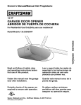
Owner's Manual/Manual Del Propietario
112 HP
GARAGE DOOR OPENER
ABRIDOR DE PUERTA DE COCHERA
For Residential Use Only/S61o para uso residencial
Model/Modelos
139.53960SRT
139.53971SRT
• 139.53968SRT
• 139.53973SRT
• 139.53970SRT
m
f.n
.-r-
Zt
CAUTION:
Read and follow all safety rules
and operating instructions before
first use of this product.
PRECAUCION:
Leer y seguir todas las reglas de
seguridad y las instrucciones de
operaci6n antes de usar este
producto por primera vez.
Fasten the manual near the garage
door after installation.
Guardar este manual cerca de la
puerta del garaje.
regul_ons
er{Bcbve
Comphes _ w=thUL
January
19_3 325
C_
US
Cump_e con las
Regl_menta_ones UL 325
en vlgenc_a (lesde el 1 (_e
enero d6 1993
Sears, Roebuck and Co., Hoffman
www.sears corn/craftsman
Estates,
IL 60179
U.S.A
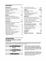
TABLE
OF CONTENTS
Introduction
2-7
Safety symbol and signal word review
.....
Preparing your garage door .................
Tools needed ........................
Planning
..........
Adjustment
28.30
2
Adjust the travel limits...
... 26
3
3
Adjust the force .......
• 29
30
Test the safety reversal system.
Test the safety reversing sensor
4-5
Carton inventory ..............
6
Operation
Hardware inventory
7
Operatton safety instructions
................
Assembly
8.11
Assemble the rail and install trolley
Fasten rail to motor unit and install idler pulley
31.34
8
9
32
32
33
34
10
Tighten the chain .............
11
Having a problem'_
11-27
35-36
Programming
To add a hand-held remote control .
To erase all codes
. .
11
12-13
35
35
Install the header bracket .........
14
3-Function Remotes
Attach the rail to the header bracket .........
15
To add or change a Keyless Entry PIN
Position the opener
.......
Hang the opener ........
Install the door control ..............
16
17
18
Repair
Install the light and lens
19
...............
......
Instalt the safety reversing sensor .
Fasten the door bracket ......
21-23
24-25
Connect the door arm to the trolley ....
26-27
37.38
37
....
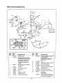
Motor unit assembly parts..
20
35
36
...
Parts
Rail assembly parts
Installation parts ....
Attach the emergency release rope and handle ..... 19
Electncal requirements
31
...31
Using the wall-mounted Door Control
Install chain/cable and attach sprocket cover
Installation safety instructions .......
Determine the header bracket location .....
..
Ustng your garage door opener
To open the door manually
Care of your garage door opener
Installation
30
37
......
38
Accessories
39
Warranty
39
Service
Numbers
Back
cover
INTRODUCTION
Safety Symbol
and Signal Word Review
This garage door opener has been designed and tested to offer safe service prowded it _sinstalled, operated,
maintained and tested in strict accordance with the instructions and warnings contained in this manual
!
4tI WARNING
When you see these Safety Symbols and Stgnal
Words on the following pages, they will alert you to
the possiblhty of serious injury or death ff you do
not comply whththe warnings that accompany them.
The hazard may come from something mechanical
or from electnc shock Read the warnings carefully
Mechanical
[
AWARNING
l
Electrical
[
CAUTION
When you see th_sSignal Word on the following
pages, _tw_ll alert you to the posstbdlty of damage to
your garage door and/or the garage door opener ff
you do not comply wTth the cautionary statements
that accompany [t Read them carefully
l
2
Preparing
your
garage
door
WARNING
Before you begin"
• Disable locks
To preventposs_b]eSERIOUSINJURY013DEATH
• ALWAYScall a traJneddoor systemsteohmcian_f
garagedoor brads,st_cks,or is out of balance An
unbalancedgaragedoor may not reversewhen
required
• NEVERtry to loosen, move or adjust garagedoer,door
spnngs, cables pulleys, bracketsor theLrhardware,all
of which are under EXTREMEtension
• DisableALL locks and removeALL ropesconnectedto
garagedoor BEFOREinstalling and operatinggarage
door openerto avoid entanglement
• Remove any ropes connected to garage door
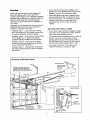
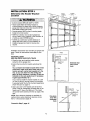
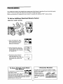
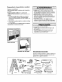
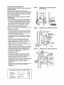
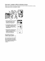
• Complete the following test to make sure your
garage door _sbalanced and _snot sbckmg or
binding
1 Lift the door about halfway as shown Release
the door If balanced, it should stay in place
supported entirely by its springs.
2. Raise and lower the door to see If there is any
binding or sticking.
If your door binds, sticks, or is out of balance, call
a trained door systems techmcian.
CAUTION
To preventdamageto garagedoor and opener
• ALWAYSd_sablelocks beforeJnstalhng
and operating
the opener
• ONLYoperategaragedoor openerat 120V,60 Hzto
avoid malfunctionand damage
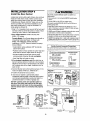
Sectional Door
One-Piece Door
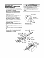
Tools
needed
During assembly,mstallabon and adjustment of the
opener, instructions w_llcall for hand tools as
dlustratedbelow
Pencil
Level
Hack Saw
Tape Measure
Wire
Drill
Stepladder
3/16", 5/16'and
5!32" DrLII Bits
CutLers
_--_
PherS
Screwdriver
AdluStable
Encl Wrench
Do you have an access door in addition to the
garage door? If not, Model 53702 Emergency Key
Release is required. See Accessories page.
Planning
Identify the type and height of your garage door.
Survey your garage area to see if any of the
conditions below apply to your installation. Additional
materials may be required. You may find it helpful to
refer back to this page and the accompanying
illustrations as you proceed with the installation of
your opener.
Depending on your requirements, there are several
installation steps which may call for materials or
hardware not included in the carton.
• Installation Step 1 - Look at the wall or ceiling
above the garage door. The header bracket must
be securely fastened to structural supports.
• Installation Step 5 - Do you have a finished ceiling
in your garage? If so, a support bracket and
additional fastening hardware may be required.
• Installation Step 10 - Depending upon garage
construction, extension brackets or wood blocks
may be needed to install sensors.
• Installation Step 10-Alternate floor mounting of
the safety reversing sensor will require hardware
not provided.
Look at the garage door where it meets the floor.
Any gap between the floor and the bottom of the
door must not exceed 1/4". Otherwise, the safety
reversal system may not work properly. See
Adjustment Step 3. Floor or door should be
repaired.
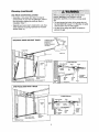
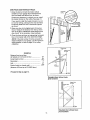
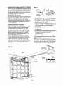
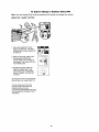
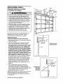
SECTIONAL DOOR INSTALLATIONS
• Do you have a steel, aluminum, fiberglass or glass
panel door? If so, horizontal and vertical reinforcement is required (Installation Step 11).
• The opener should be installed above the center of
the door. If there is a torsion spring or center
bearing plate in the way of the header bracket, it
may be installed within 4 feet to the left or right of
the door center. See Installation Steps 1 and 11.
• If your door is more than 7 feet high, see rail
extension kits listed on Accessories page.
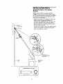
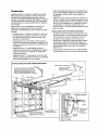
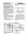
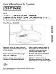
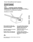
SECTIONAL DOOR INSTALLATION
FINISHED
Horizontal and vertical reinforcement
CEILING
is requited.
See page 17.
(fiberglass, steel, aluminum, door with
Rail
Header Wall
Motor unit
Header
Bracket
Trolley
Stop Bolt
CLOSED POSITION
Trolley
Chain
Emergency
Release
Rope & Handle
3ap between
floor
and bottom of door
must not exceed
1/4".
Safety
Reversing
Sensor
Door
Arm
Door
Bracket
Planning
(continued)
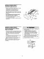
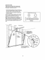
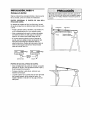
ONE-PIECE DOOR INSTALLATIONS
Without a properlyworkingsafetyreversalsystem,
persons(particularly small children) could be
SERIOUSLY
INJUREDor KILLEDby a closing garage
door
• The gap betweenthe bottomof the garagedoorand
the floor MUSTNOTexceed1/4". Otherwise,the safety
reversalsystem may not work properly.
• The floor or the garagedoor MUSTbe repairedto
eliminatethe gap.
• Generally, a one-piece door does not require
reinforcement. If your door is lightweight, refer to
the information relating to sectional doors in
Installation Step 11.
• Depending on your door's construction, you may
need additional mounting hardware for the door
bracket (Step 11).
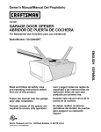
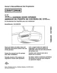
ONE-PIECE DOOR WITHOUT TRACK
FINISHED CEILING
Support bracket
& fastening
hardware is required.
See page 17
Header Wall
Motor unit
Rail
Wall-mounted
Door Control
Access
CLOSED POSITION
I /
Door
Trolley Stop Bolt
I
['t]
Cable
Trolley
ol
Bracket
Rail
Door Bracket
Emergency
- Release
Rope & Handle
Cu_ed
Sensor
Gap between floor
and bottom of door must not exceed 1/4".
Door
Arm
}eader
Safety Reversing Sensor
Vail
Door
Arm
Garage Door
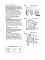
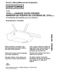
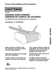
ONE-PIECE DOOR WITH TRACK
CLOSED
Trolley
Access
Stop Bolt
POSITION
Cable
Chain
I
Door
Curved
I
Bracket
Rail
Ol
Emergency
Bracket
feb
Safety
Reversing Sensor
Floor must be level
ss width of door
Door
Reversing
Sensor
5
Straight
Release
Door
Arm
Handle
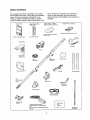
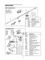
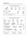
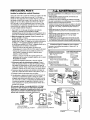
Carton
Inventory
Your garage door opener is packaged in one carton
which contains the motor unit and the parts illustrated
below. Note that accessories will depend on the
model purchased. If anything is missing, carefully
check the packing material. Parts may be stuck in the
Models 53971
Models 53960, 53968,
foam. Hardware for assembly and installation is
shown on the next page. Save the carton and
packing material until installation and adjustment is
complete.
Models 53970 (1), 53973 (1)
Models 53960 (1), 53968 (2),
53970 (1)1 53971 (2), 53973 (1)
Compact 3-Function Remote Control
Three-Function Remote Control
with Visor Clip
Premium Control Console
Door Control Button
Model 53973
Light Lens
Trolley
©
/
Multi-Function
Keyless Entry
Rail
Center/Back
Sections
Chain
Idler Pulley
Sprocket Cover
Hanging Brackets
J
Rail
Front (header)
Section
Curved Door
Arm Section
Door Bracket
Header Bracket
2-Conductor
Bell Wire
White & White/Red
Safety Sensor
Bracket
(2) Safety Reversin9 Sensors
(1 Sending Eye and 1 Receiving Eye)
with
2-Conductor White & White/Black Bell Wire
attached
Safety Labels
and
Literature
Straight Door
Arm Section
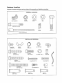
Hardware
Inventory
Separate all hardware and group as shown below for the assembly and installation procedures.
ASSEMBLY HARDWARE
Lock Nut
1/4"-20 (2)
Chain Spreader (2)
Lock Washer
3/8" (1)
Nut
3/8" (1)
i
)//))//)///)
_,
Bolt 1/4"-20 x 1-3/4" (2)
:,Ji,li,lli,i
!_l,
!,,!dii,,,,,_,i:li,,,i:il,
:i
I¸¸
i:,i,,
il,,
i
,;,
i!,ii,,i,,li,
;i,
¸
i,i,';',illl,
,
Master
Link (2)
,
l,i,;_,li,_l',_,ii, I
Idler Bolt(1)
Trolley Threaded Shaft (1)
INSTALLATION HARDWARE
0
Carriage Bolt
1/4"-20xl/2" (2)
Wing Nut
1/4"-20 (2)
©
Ring
Fastener (3)
©
_llLIlll_lllllllllll_
Lag Screw
5/16"-9xl-5/8"
Hex Screw
5/16"-18x7/8"
(2)
Handle
Nut 5116"-18 (8)
(4)
Lock Washer 5/16" (7)
Insulated
Staples (30)
i
IllllllLIIIIl!lL_llll[_
Lag Screw
Screw 6-32x1" (2)
5116"-18xl-7/8" (2)
(_
i!lLIIllLillllllllLlilllllllll[!lll_
Rope
Carriage Bolt
5116"-18x2-1/2" (2)
Dry Wall Anchors (2)
oll
Clevis Pin
5116"x1-112"(1)
Spacer (2)
o_
Clevis Pin
5/16"x1-114_ (1)
J
Clevis Pin
5/18"x1" (1)
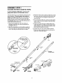
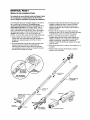
ASSEMBLY
Assemble
STEP
the
Rail
1
& Install
the
Trolley
To avoid installation difficulties, do not run the
garage door opener until instructed to do so,
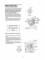
The front rail has a cut out "window" at the door end
(see illustration). The hole above this window Is
larger on the top of the rail than on the bottom. A
smaller hole 3-112" away is close to the rail edge.
Rotate the back rail so it has a similar ho/e close to
the opposite edge, about 4-314" from the far end. A
3-piece rail uses two back rails.
3. Place the motor unit on packing material to protect
the cover, and rest the back end of the rail on top.
For convenience, put a support under the front
end of the rail.
4. As a temporary trolley stop, clamp a locking pliers
onto the rail, 8" from the center of the idler pulley
hole, as shown.
1. Remove the straight door arm and clevis pin
packaged inside the front rail and set aside for
Installation Step 12.
5. Check to be sure there are 4 black plastic wear
pads inside the inner trolley. If they became loose
during shipping, check all packing material. Snap
them back into position as shown.
2. Align the rail sections on a flat surface exactly as
shown and slide the tapered ends into the larger
ones. Tabs along the side will lock into place.
6. Connect the inner and outer trolleys as shown.
7. Slide the trolley assembly along the rail from the
back end to the locked pliers.
Trolley
End
Back Rails
(TO MOTOR UNIT)
Inner TrolLey
Wear Pads
8
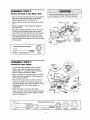
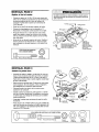
ASSEMBLY
STEP 2
Fasten the Rail to the Motor Unit
To avoid seriousdamageto garagedoor opener,use
only those screws mounted in the top of the opener.
• Insert a 1/4"-20xl-3/4 bolt into the cover protection
bolt hole on the back end of the rail as shown.
Tighten securely with a 1/4"-20 lock nut.
• Remove the two screws from the top of the motor
unit.
Screws
• Attach spreaders to the U bracket by snapping
them into place.
Motor Unit
Sprocket
"U" Bracket
• Place the U bracket, flat side down, on the motor
unit and align the bracket holes with the screw
holes. Fasten with the previously removed screws.
Bolt
I
Cover
• Align the rail assembly with the top of the motor
unit. Slide the rail end onto the U-bracket, all the
way to the steps that protrude on the top and sides
of the bracket.
into Back Slots1
then Snap Tab
Into FrontSIot
SLIDE RAIL TO STOP
ON TOP AND SIDES
OF BRACKET
Lock Nut
HARDWARE SHOWN ACTUAL SIZE
_'_'1
Bolt 1/4"-20 x 1-3/4
ASSEMBLY
Install
the
STEP
Idler
1/#-20
3
Pulley
Chain and
Cable
• Lay the chain/cable beside the rail, as shown.
Grasp the end with the cable loop and pass
approximately 12" of cable through the window.
Allow it to hang until Assembly Step 5.
• Remove the tape from the idler pulley. The inside
center should be pre-greased. If dry, regrease to
ensure proper operation.
Bolt --_
TrcJIley
St_p HoIe
I
• Place the idler pulley into the window as shown.
• Insert the idler bo?tfrom the top through the rail
and pulley. Tighten with a 3/8" lock washer and nut
underneath the rail until the lock washer is
compressed.
Inside
• Rotate the pulley to be sure it spins freely.
• Insert a 1/4"-20xl-3/4 bolt into the trolley stop hole
in the front of the rail as shown. Tighten securely
with a 1/4"-20 lock nut.
Pulley
i
Idler
Grease
Pulley
3/8"Lock
Washer_
• Cable
_
Loop
Idler Pulley
HARDWARE SHOWN ACTUAL SIZE
Idler B01t
Bolt1/4"-20 x 1-3/4
9
L0ckNut 1/4"-20
Nut 3/8"
LockWasher 3/8"
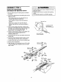
ASSEMBLY
STEP 4
Install the Chain/Cable
and Attach the Sprocket
Toavoid possible serious injury to fingers from moving
garagedoor opener:
• ALWAYSkeephand clear of sprocket while operating
opener.
• Securelyattach sprocket cover BEFOREoperating.
Cover
1. Pull the cable around the idler pulley and toward
the trolley.
2. Connect the cable loop to the retaining slot on the
trolley, as shown:
• From below, push pins of master link bar up
through cable loop and trolley slot.
• Push master link cap over pins and past pin
notches.
Dispensing Carton
• Slide clip-on spring over cap and onto pin
notches until both pins are securely locked in
place.
Leave Chain and Cable
Inside Dispensin9
3. With the trolley against the pliers, dispense the
remainder of the cable/chain along the rail toward
the motor unit and around the sprocket. The
sprocket teeth must engage the chain.
4. Check to make sure the chain is not twisted, then
connect it to the threaded shaft with the
remaining master link.
5. Thread the inner nut and lock washer onto the the
trolley shaft.
6. Insert the trolley threaded shaft through the hole
in the trolley. Be sure the chain is not twisted.
7. Loosely thread the outer nut onto the trolley shaft.
Carton
to Prevent
Keep Chain and Cable
Taut When Dispensing
8. Remove the locking pliers.
I
9. Align the tabs on the sprocket cover with the slots
in the mounting plate. Squeeze cover and insert
tabs in slots.
i
i
<
Master
Link Cap
Cable
Loop
Pin
Notch
Sha_
Link Bar
Idler
Hole
Hole
Master
Link Bar
Cable
10
Sprocket
Cover ---{r't
_"
;
Front
Tab Slot
',
[-'].,J
_,
Motor Unit
Sprocket
Back
Tab Slot
Kinking,
iii
ASSEMBLY
Tighten
the
STEP
5
Chain
Figure 1
• Spin the inner nut and lock washer down the
threaded shaft, away from the trolley.
Outer Lock
TroLley
Nut
Washer Shaft
• To tighten the chain, turn outer nut in the direction
shown (Figure 1).
To Tigh,en Outer Nut ---i_-1
[
• When the chain is approximately 1/2" above the
base of the rail at its midpoint, re-tighten the inner
nut to secure the adjustment.
/
'T°nTI_Nh
rutn
Sprocket noise can result if chain is too loose.
When installation is complete, you may notice some
chain droop with the door closed. This is normal. If
the chain returns to the position shown in Figure 2
when the door is open, do not re-adjust the chain.
NOTE.: During future maintenance, ALWAYS pull the
emergency release handle to disconnect trolley
before adjusting chain.
Figure 2
,,
Chain
I
I
tIJI
i
II ,1 ,,i,_
/
Base _)fRail
i
1111 il II
II/2
Inch
Mid length of Rail
NOTE: You may notice loosening of chain after
Adjustment Step 3 (Test the Safety Reversal
System). Check for proper tension and readjust
chain if necessar_ Then repeat Adjustment Step 3.
You have now finished assembling your garage
door opener. Please read the following warnings
before proceeding to the installation section:
I NSTALLATION
IMPORTANT INSTALLATION INSTRUCTIONS
To reduce the risk of severe injury or death:
1. READAND FOLLOWALL INSTALLATION
WARNINGS
AND INSTRUCTIONS.
8. NEVERwearwatches,rings or looseclothing while
installing or servicingopener.Theycould be caughtin
garagedoor or openermechanisms.
9. Installwall-mountedgaragedoor control:
• within sight of the garagedoor
• out of reachof children at minimumheightof 5 feet
• awayfrom all moving parts of the door.
10. Placeentrapmentwarninglabelon wall nextto garage
door control.
11. Placemanualrelease/safetyreversetest label in plain
view on inside of garagedoor.
12. Uponcompletionof installation,test safety reversal
system. DoorMUSTreverseon contactwith a oneinch high object(or a 2x4 laid flat) on the floor.
2. Install garagedoor opener only on properlybalanced
and lubricatedgarage door.An improperly balanced
door may not reversewhen requiredand could result in
severeinjury or death.
3. All repairsto cables,spring assembliesand other
hardwareMUSTbe macleby a traineddoor systems
technicianbeforeinstalling opener.
4. Disableall locks and remove all ropesconnectedto
garagedoor beforeinstalling openerto avoid
entanglement.
5. Install garagedoor opener 7 feet or more abovefloor.
6. Mount emergencyreleasehandle 6 feet abovefloor.
7. NEVERconnectgaragedoor openerto powersource
until instructed to do so.
11
INSTALLATION
Determine
Location
the
STEP
Header
1
Bracket
Vertical
Centerline
__
FinishedCeiling
2x4
StrucJural
To preventpossible SERIOUSiNJURYor DEATH:
• HeaderbracketMUSTbe RIGIDLYfastenedto
structural support on headerwall or ceiling, otherwise
garage door might not reversewhen required.DO NOT
install headerbracketover drywall
• Concreteanchors MUST be used if mounting header
bracketor 2x4 into masonry,
• NEVERtry to loosen, move or adjust garagedoor,
springs, cables,pulleys, brackets,or their hardware,all
of which are under EXTREMEtension.
• ALWAYScall a trained door systemstechnicianif
garagedoor binds, sticks, or is out of balance.An
unbalancedgaragedoor might not reversewhen
required.
Installation procedures vary according to garage door
types. Follow the instructions which apply to your
door.
Ceiling
I
Header Wall
SECTIONAL DOOR
AND ONE-PIECE DOOR WITH TRACK
1. Close the door and mark the inside vertical
centerline of the garage door.
2. Extend the line onto the header wall above the
door.
._L--_2"
Highest
of Travel
You can fasten the header bracket within 4 feet
of the left or right of the door center only if a
torsion spring or center bearing plate is in the
way; or you can attach it to the ceiling (see
page 14) when clearance is minimal. (It may be
mounted on the wall upside down if necessary,
to gain approximately 1/2".)
If you need to install the header bracket on a 2x4
(on wall or ceiling), use lag screws (not provided)
to securely fasten the 2x4 to structural supports as
shown here and on page 13.
--
3. Open your door to the highest point of travel as
shown. Draw an intersecting horizontal line on the
header wall 2" above the high point, This height
will provide travel clearance for the top edge of the
door.
Track
Point
Sectional door
with curved
track
DoOr
Header Wall
Track
'--2"
NOTE: Door clearance brackets are available for
sectional doors when headroom clearance is less
than 2". See accessory page 39.
One-piece
door with
horizontal
track
Proceed to Step 2, page 14.
12
of Travel
ONE-PIECE DOOR WITHOUT TRACK
Unfinished
Ceiling
1. Close the door and mark the inside vertical
centerline of your garage door. Extend the line
onto the header wall above door, as shown.
Header Wall
If headroom clearance is minimal, you can install
the header bracket on the ceiling. See page 14.
Vedical
Centerline
If you need to install the header bracket on a 2x4
(on wall or ceiling), use lag screws (not provided)
to securely fasten the 2x4 to structural supports
as shown.
CEILING
MOUNT
FOR
HEADER
BRACKET
2. Open your door to the highest point of travel as
shown. Measure the distance from the top of the
door to the floor. Subtract the actual height of the
door. Add 8" to the remainder. (See Example).
3. Close the door and draw an intersecting horizontal
line on the header wall at the determined height.
NOTE: If the total number of inches exceeds the
height available in your garage, use the maximum
height possible, or refer to page 14 for ceiling
installation.
Header Wall
/
Highest Point
of Travel
EXAMPLE
Distance from top of door
(at highest point of travel) to floor ......................
Actual height of door..........................................
Remainder ..........................................................
Add .....................................................................
92"
-88"
4"
"7
+8"
Bracket height on header wall............................ =12"
Q
(Measure UP from top of CLOSED door.)
Proceed toStep _ page 14.
One-piece door without track:
jamb hardware
Floor
13
One-piece door without track:
pivot hardware
INSTALLATION
STEP 2
Install the Header Bracket
Wall Mount
You can attach the header bracket either to the wall
above the garage door, or to the ceiling. FoUow the
instructions which will work best for your particular
requirements. Do not install the header bracket
over drywall. If installing into masonry, use
concrete anchors (not provided).
WALL HEADER BRACKET INSTALLATION
• Center the bracket on the vertical centerline with
the bottom edge of the bracket on the horizontal
line as shown (with the arrow pointingtoward the
ceiling).
• Mark the vertical set of bracket holes, Drill 3/16"
pilot holes and fasten the bracket securely to a
structuralsupportwith the hardware provided.
Optional
Mounting Holes
-
Ve_ical
Centerline
Header
Wall
Lag Scows
5/16"x9x1-518"
2x4
Structural
Suppo_
-Door Spring
HARDWARE
/
SHOWN ACTUAL SIZE
/
-
LIl l llllllLlilLIl
Garage
Door -
Highest Point of
Garage
Door Travel
Centerline
Lag Screw
5/16"-9xl-5/8"
CEILING HEADER BRACKET INSTALLATION
• Extend the vertical centerline onto the ceiling as
shown.
• Center the bracket on the vertical mark, no more
than 6" from the wall. Make sure the arrow is
pointing away from the wall. The bracket can be
mounted flush against the ceiling when clearance
is minimal.
- Finished
• Mark the side holes. Drill 3/16" pilot holes and
fasten bracket securely to a structural support with
the hardware provided.
Reader
Ceiling
-
_
B_acket
6" Maximum
Door
Ceiling Mounting Holes
--
Lag Screws
5/16"xgxl-5/8"
- Header Wall-
Centerline
14
INSTALLATION
Attach
Bracket
the
STEP 3
Rail
to the
Header
NOTE: (Opbonal) With an exlsbng Craftsman
mstallabon, you may re-use the old header bracket
with the two plastic spacers included fn the hardware
bag Place the spacers reside the bracket on each
side of the rail, as tllustrated
• Position the opener on the garage floor below the
header bracket Use packing material as a
protective base NOTE: If the door spnng ts m the
way you'll need help Have someone hold the
opener securely on a temporary support to allow
the rail to clear the spnng
• Position the front rail end within the header bracket
and join with a 5/16"x1-1/2" clevis pin as shown
• Insert a nng fastener to secure
Header Bracket
0
Spring
Mounting
Hole
Header
Bracket
0
HOle
3PTION
WITH
EXISTING
CRAFTSMAN
INSTALLATION
Garage
Door
__
HARDWARE SHOWN ACTUAL SIZE
O
Clev=s P=n5/16"xl-1/2'
Ring fastener
15
OpenerCaKonor
Tempora_
Suppo_
iii
INSTALLATION
Position
the
STEP
4
Opener
Follow instructions which apply to your door type as
illustrated.
SECTIONAL DOOR OR ONE-PIECE DOOR WITH
TRACK
A 2x4 laid flat is convenient for setting an ideal doorto-rail distance.
Outer Trolley
• Raise the opener onto a stepladder. You will need
help at this point if the ladder is not tall enough.
• Open the door all the way and place a 2x4 laid flat
on the top section beneath the rail.
• If the top section or panel hits the trolley when you
raise the door, pull down on the trolley release arm
to disconnect inner and outer sections. Slide the
outer trolley toward the motor unit. The trolley can
remain disconnected until Installation Step 12
is completed.
ENGAGED
RELEASE_D
ONE-PIECE DOOR WITHOUT TRACK
• With the door fully open and parallel to the floor,
measure the distance from the floor to the top of
the door.
i
• Using a stepladder as a support, raise the top of
the opener to this height.
• The top of the door should be level with the top of
the motor unit. Do not position the opener more
than 2" above this point.
16
Inner Trolley
INSTALLATION
STEP
5
Hang the Opener
To avoid possibleSERIOUSINJURYfrom a falling
garagedoor opener,fasten it SECURELY
to structural
supports of the garage.Concreteanchors MUSTbe used
if installingany brackets into masonry.
Two representatLve installations are shown. Yours
may be different. Hanging brackets should be angled
(Figure 1) to provide rigid support. On finished
ceilings (Figure 2), attach a sturdy metal bracket to
structural supports before installing the opener. This
bracket and fastening hardware are not provided.
(See Accessories.)
Figure 1
Str'Jctural
1. Measure the distance from each side of the motor
unit to the structural support.
Lag Screws
5/16"-18xl-7/8"
2, Cut both pieces of the hanging bracket to required
lengths.
Measure
Distance
\,
',
3. Drill 3/16" pilot holes in the structural supports.
4. Attach one end of each bracket to a support with
5/16"-18xl-7/8" lag screws.
5. Fasten the opener to the hanging brackets with
5/16"-18x7/8" hex screws, lock washers and nuts.
6. Check to make sure the rail is centered over the
door (or in line with the header bracket if the
bracket is not centered above the door).
5/16"-!8×718"Screw
5/16" Lock Washer
5/16"-18 Nut
7. Remove the 2x4. Operate the door manually. If
the door hits the rail, raise the header bracket.
Figure 2
NOTE: Do NOT connect power to opener at this
time.
Hidden
..-
.-_
5/16"-18xl-718"
Bracket
(Not Provided)_"'_
"-5/16"-18x718"$crew
_.--_
_ . .-
:::..-"_'_
_._._J
_
(NotProvided)
5/16"-18x7/e" Screw
5/16" Lock Washer
5/16"-18 Nut
HARDWARESHOWNACTUALSIZE
5/165/16"
Lock
Washer18_i_,
Ll,l llLlllltI,LIlllll.
Lag Screw
5116"-18x1-7/8"
5/16"- 18x7/8"
Nut 5/16"-18
Lock Washer 5/16"
17
.TI::]_ !_;'_'
INSTALLATION
Install
the Door
STEP
Control
6
TopreventpossibleSERIOUSINJURYor DEATHfrom
electrocution:
Locate door control within sight of door, at a minimum
height of 5 feet where small children cannot reach,
away from moving parts of door and door hardware.
If installing into drywall, drill 5/32" holes and use the
anchors provided. For pre-wired installations (as in
new home construction), it may be mounted to a
single gang box (Figure 2).
• Besurepoweris not connectedBEFORE
installingdoor
control.
• ConnectONLYto 24 VOLTlow voltagewires.
TopreventpossibleSERIOUS
INJURYor DEATH
from a
closinggaragedoor:
• Installdoor control within sight of garagedoor,out of
reachof childrenat a minimumheightof 5 feet,andaway
from all movingparts of door.
• NEVERpermitchildrento operateor playwithdoorc0ntrol
pushbuttonsor remotecontroltransmitters.
• Activatedoor ONLYwhenit canbe seenclearly,is properly
adjusted,andthereareno obstructionsto door travel.
ALWAYS
keepgaragedoor in sight untilcompletelyclosed.
NEVERpermit anyoneto crosspathof closinggaragedoor.
1. Strip 1/4" of insulation from one end of bell wire and
connect to the two terminal screws on back of door
control by color: white to 2 and white/red to 1.
2. Door Control Button: Fasten securely with
6ABx1-l/2" screws.
Console Model: Pry off cover along one side with a
screwdriver blade (see Figure 1). Fasten with
6ABx1-1/4" self-tapping screws (standard
installation) or 6-32x1" machine screws (into gang
box) as follows:
Outside Keylock Accessory Connections
To opener terminal screws: white to 2; white/red to 1
• Install bottom screw, allowing 1//8" to protrude
above wall surface.
• Position bottom of door control on screw head and
slide down to secure. Adjust screw for snug fit.
• Drill and install top screw with care to avoid
cracking plastic housing. 13o not overtighten.
• Insert top tabs and snap on cover.
ACTUAL SIZE
6AB x 1-1/2" Screw
Door Control Button
H; IAI212Il1111/12,,t
iSIcl'el/VJ_
_
3. (For standard installation only) Run bell wire up
wall and across ceiling to motor unit. Use insulated
staples to secure wire in several places. Be careful
not to pierce wire with a staple, creating a short or
open circuit.
4. Connect the bell wire to the terminal screws on the
motor unit panel: white to 2; white/red to 1.
5. Position the antenna wire as shown.
Control Console (std installation)
Control Console (pre-wired)
Figure 1
REMOVE
& REPLACE
PRE-WtRED
INSTALLATION
Insert Top
Twist
DO NOT connect power and operate opener at
this time, The trolley will travel to the full open
position but will not return to the close position
until the sensor beam is connected and properly
aligned.
Tabs
__._._.
First
Here
To Remove,
Lighted
Push Button
.
/
Screws
Terminal
Bell
Wire
Top
Mounting
DOOR CONTROL BUTTON
Hole
> Terminal
Sorews
Bottom
Ben
Wire
(BACK V_EW)
_
Mounting
_
(BACK
Hole
VIEW)
PREMIUM
CONTROL
CONSOLE
Back Panel
of Opener
18
Dry Wall Anchors
Figure 2
COVER
6. Use tacks or staples to permanently attach
entrapment warning label to wall near door control,
and manual release/safety reverse test label in a
prominent location on inside of garage door.
-
nsulated
Staples
I 116!; I21
IxII ,! ': Ictr
le!; II
TO Replace,
:_F==_===_==
_v
HARDWARE SHOWN
_] I_!ll_illlllliltltl Illliillllil_>
24 Volt
2-Conductor
Bell Wire in
Gang Box
INSTALLATION
Install
STEP
7
the Light and Lens
• Install a 75 watt maximum light bulb in the socket.
The light will turn ON and remain lit for
approximately 4-1/2 minutes when power is
connected. Then the light will turn ore
• Apply slight pressure on the sides of the lens and
slide the tabs into the slots in the end panel. (See
illustration .)
Light
Lens
I
I*"
" .
• For convenience, the lens may be installed
after Adjustment Step 4 on page 30.
Lens
Guide
_g._
• To remove, reverse the procedure. Use care to
avoid snapping off lens tabs.
• Use standard neck Garage Door Opener bulbs for
replacement.
INSTALLATION
STEP
Attach
the Emergency
Rope and Handle
ens
Tab
Lens
Light Bulb
8
Release
• To preventpossibleSERIOUSINJURYor DEATHfrom
a falling garagedoor:
- If possible,useemergencyreleasehandleto
disengagetrolley ONLYwhen garagedoor is
CLOSED.Weakor brokensprings or unbalanced
door couldresult in an open door fallingrapidly
and/or unexpectedly.
- NEVERuseemergencyreleasehandleunlessgarage
doorway is clearof personsand obstructions.
• NEVERuse handleto pull door open or closed,If rope
knot becomesuntied,you could fall.
• Thread one end of the rope through the hole in the
top of the red handle so "NOTICE" reads right side
up as shown. Secure with an overhand knot at
least 1" from the end of the rope to prevent
slipping.
• Thread the other end of the rope through the hole
in the release arm of the outer trolley.
• Adjust rope length so the handle is 6 feet above
the floor. Secure with an overhand knot,
NOTE: flit is necessary to cut the rope, heat seal
the cut end with a match or lighter to prevent
unraveling.
Trolley
Trolley
Eme_genc
Release Handle
19
Overhand
Knot
INSTALLATION
Electrical
STEP
9
Requirements
Toprevent possible SERIOUSINJURYor DEATHfrom
electrocutionor fire:
• Be sure power is notconnectedto the opener,and
disconnectpowerto circuit BEFOREremoving coverto
establishpermanentwiring connection.
• Garagedoor installationand wiring MUSTbe in
compliancewith all localelectricaland building codes.
• NEVERuse an extensioncord, 2-wire adapter,or
changeplug in any way to make it fit outlet. Besure
the openeris grounded.
To avoid installation difficulties, do not run the
opener at this time.
To reduce the risk of electric shock, your garage door
opener has a grounding type plug with a third
grounding pin. This plug will only fit into a grounding
type outlet. If the plug doesn't fit into the outlet you
have, contact a qualified electrician to install the
proper outlet.
PERMANENT WIRING
CONNECTION
If permanent wiring is required by your local
code, refer to the following procedure.
To make a permanent connection through the 7/8"
hole in the top of the motor unit:
• Remove the motor unit cover screws and set the
cover aside,
Ground Tab
Green
Ground Screw
• Remove the attached 3-prong cord.
• Connect the black (line) wire to the screw on the
brass terminal; the white (neutral) wire to the
screw on the silver terminal; and the ground wire
to the green ground screw. The opener must be
grounded.
• Reinstall the cover.
White /
2O
INSTALLATION
STEP
Install
Reversing
The Safety
10
Sensor
• Be sure poweris not connectedto the garagedoor
openerBEFOREinstalling the safety reversingsensor.
• Toprevent SERIOUSINJURYor DEATHfrom a closing
garagedoor:
- Correctlyconnectand align the safety reversing
sensor.This required safetydevice MUSTNOTbe
disabled.
- Installthe safety reversing sensor so beam is NO
HIGHERthan 6"above garagefloor.
The safety reversing sensor must be connected
and aligned correctly before the garage door
opener will move in the down direction,
IMPORTANT INFORMATION ABOUT
THE SAFETY REVERSING SENSOR
When properly connected and aligned, the sensor
will detect an obstacle in the path of its electronic
beam. The sending eye (with an orange indicator
light) transmits an invisible light beam to the
receiving eye (with a green indicator light). If an
obstruction breaks the light beam while the door is
closing, the door will stop and reverse to full open
position, and the opener lights will flash 10 times.
The units must be installed inside the garage so that
the sending and receiving eyes face each other
across the door, no higher than 6" above the floor.
Either can be installed on the left or right of the door
as long as the sun never shines directly into the
receiving eye lens.
The mounting brackets are designed to clip onto the
track of sectional garage doors without additional
hardware.
If it is necessary to mount the units on the wall, the
brackets must be securely fastened to a solid
surface such as the wall framing. Extension brackets
(see accessories) are available if needed. If
installing in masonry construction, add a piece of
wood at each location to avoid drilling extra holes in
masonry if repositioning is necessary.
The invisible light beam path must be unobstructed.
No part of the garage door (or door tracks, springs,
hinges, rollers or other hardware) may interrupt the
beam while the door is closing.
!i
Invisible Light Seam
Protection Area
Facing the door from inside the garage
21
SensorBeam
6"maximum
above floor
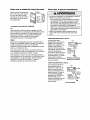
INSTALLING THE BRACKETS
Figure 1
DOOR TRACK MOUNT (RIGHT SLOE)
Be sure power to the opener is disconnected.
Install and align the brackets so the sensors will face
each other across the garage door, with the beam no
higher than 6" above the floor.They may be installed
in one of three ways, as follows.
Door
Track
indicator
Light
Garage door track installation (preferred):
• Slip the curved arms over the rounded edge of
each door track, with the curved arms facing the
door. Snap into place against the side of the track.
it should lie flush, with the lip huggingthe back
edge of the track, as shown in Figure 1.
_ensor
Bracket
If your door track wilt not supportthe bracket
securely, wall installationis recommended.
Wall installation:
WALL MOUNT (RIGHT SIDE)
Figure 2
• Place the bracket against the wall with curved arms
facing the door. Be sure there is enough clearance
for the sensor beam to be unobstructed.
Extension
Bracket
(See
Accessories)
• if additional depth is needed, an extension bracket
(see Accessories) or wood blocks can be used.
(Provided
Extension
with
Bracket)
• Use bracket mounting holes as a template to locate
and drill (2) 3/16" diameter pilot holes on the wall at
each side of the door, no higher than 6" above the
floor.
• Attach brackets to wall with lag screws
(not provided).
• If using extension brackets or wood blocks, adjust
right and left assemblies to the same distance out
from the mounting surface. Make sure all door
hardware obstructions are cleared.
(Provided
Extension
Bracket)
Sensor
Bracket
with
-_"
Indicator
Light
Lens
Floor installation:
FLOOR MOUNT (RIGHT SIDE)
Figure 3
• Use wood blocks or extension brackets (see
Accessories) to elevate sensor brackets so the
lenses will be no higher than 6" above the floor.
Lens
Indicator
Sensor
Bracket
Light
(Provided with
Extension Sracket)
"*'
• Carefully measure and place right and left
assemblies at the same distance out from the wall.
Be sure all door hardware obstructions are cleared.
Attach with
Concrete Anchors
not provided)
• Fasten to the floor with concrete anchors as shown,
, i**e°sie°
]
Bracket
See Accessones)
t i
Q
HARDWARE SHOWN ACTUAL SIZE
Carriage Bolt
1/4"-20x1/2"
Wing Nut
1/4"o20
Staples
22
MOUNTING AND WIRING THE SAFETY SENSORS
Figure 4
• Slide a 1/4"-20x1/2" carriage bolt head into the slot
on each sensor. Use wing nuts to fasten sensors to
brackets, with lenses pointing toward each other
across the door. Be sure the lens is not obstructed
by a bracket extension. See Figure 4.
114"-20xl/2"
• Finger tighten the wing nuts.
_
Wing nut
Cardage bolt
• Run the wires from both sensors to the opener. Use
insulated staples to secure wire to wall and ceiTing.
TROUBLESHOOTING THE SAFETY SENSORS
• Strip 1/4" of insulation from each set of wires.
Separate white and white/black wires sufficiently to
connect to the opener terminal screws: white to 2
and white/black to 3.
1. If the sending eye indicator light does not g/ow
steadily after installation, check for:
• Electricpower to the opener.
• A short in the white or white/black wires. These
can occur at staples, or at screw terminal
connections.
ALIGNING THE SAFETY SENSORS
• Plug in the opener. The indicator lights in both the
sending and receiving eyes will glow steadily if
wiring connections and alignment are correct.
• Incorrectwiring between sensors and opener.
• A broken wire.
The sending eye orange indicator light will glow
regardless of alignment or obstruction. If the green
indicator light in the receiving eye is off, dim, or
flickering (and the invisible light beam path is not
obstructed), alignment is required.
2. If the sending eye indicator light g/ows steadily but
the receivingeye indicatorlight doesn't:
• Check alignment.
• Loosen the sending eye wing nut and readjust,
aiming directly at the receiving eye. Lock in place.
3. If the receivingeye indicatorlight is dim, realign
either sensor.
• Loosen the receiving eye wing nut and adjust
sensor until it receives the sender's beam. When
the green indicator light glows steadily, tighten the
wing nut.
NOTE: When the invisib/ebeam path is obstructed
or misa/igned while the door is c/osing, the door wi//
reverse. /f the door is a/ready open, it wi// not dose.
The opener /ights willflash 10 times. See page 21.
• Check for an open wire to the receiving eye.
Figure 5
Connect Wire to
Opener Terminals
Bell Wire
__
Finished __
Ceiling
Bell Wire
Door Control
Sensor
Connections _
(dotted line)
Connections
J
.' -
%
OPENER TERMINAL SCREWS
Sellsot"
Invisible Light Seam
Protection Area
23
INSTALLATION
STEP
Fasten the Door Bracket
11
' ONili,'ii!i! ii ii!!
Toprevent damageto garagedoor, reinforce insideof
Follow instructions which apply to your door type
as illustrated below or on the following page,
door with angle iron both vertically and hot z0ntaly.
A horizontal reinforcement brace should be long
enough to be secured to two vertical supports. A
vertical reinforcement brace should cover the
height of the top panel.
HARDWARE SHOWN ACTUAL SIZE
The illustration shows one piece of angle iron as the
horizontal brace. For the vertical brace, two pieces of
angle iron are used to create a "U"-shaped support
(Figure 1). The best solution is to check with your
garage door manufacturer for an opener installation
door reinforcement kit.
LltlLilitlt!l!l!i!,!illtltll!lJ
NOTE: Many vertical brace installations provide for
direct attachment of the clevis pin and door arm. In
this case you will not need the door bracket; proceed
to Installation Step 12.
5/16"-18×2-1/2"
SECTIONAL DOORS
• Center the door bracket on the previously marked
vertical centerline used for the header bracket
installation. Note correct UP placement, as
stamped inside the bracket (Figure 2).
• Position the bracket on the face of the door within
the following limits:
• Mark and drill 5/16" left and right fastening holes.
Secure the bracket as shown in Figure 1 if there is
vertical reinforcement.
if your installation doesn't require vertical reinforcement but does need top and bottom fastening holes
for the door bracket, fasten as shown in Figure 2.
A) The top edge of the bracket 2"-4" below the top
edge of the door.
B) The top edge of the bracket directly below any
structural support across the top of the door.
_dHeader
Bracket
.÷-°'_°
. .. ° ° °""
Horizontal and vertical reinforcement
...--" is needed
° """""""for ° lig
°"""
"÷" garage doOrs
h_eight
r
5/16"
Figure 2
24
"_
Nut
'
ONE-PIECE DOORS
Please read and comply with the warnings and
reinforcement instructions on the previous page.
They apply to one-piece doors also.
• Center the door bracket on the top of the door, in
line with the header bracket as shown. Mark either
the left and right, or the top and bottom holes.
• Drill 5/16" pilot holes and fasten the bracket with
hardware supplied.
HARDWARE
SHOWN ACTUAL SIZE
©
If the door has no exposed framing, drill 3/16" pilot
holes and fasten the bracket with 5/16"x1-1/2" lag
screws (not provided) to the top of the door.
NOTE: The door bracket may be installed on the top
edge of the door if required for your installation.
(Refer to the dotted line optional placement drawing.)
Drill 3/16" pilot holes and substitute 5/16"x1-112" lag
screws (not provided) to fasten the bracket to the
door.
Nut
5,16Hii
Bo,t
L 5,
kwas
6"r
IIIIIIIIIIIIIIIIIIII!IIIIIII!IIIIII
5116"-18x2-1i2"
Header Wall
2x4SuppoH
--Finished
Ceiling--
Horizontal and vertical
reinforcement is needed for
lightweight garage doors
(fiberglass, aluminum, steel,
doer with glass panel etc.)
(not provided),
For a door with no exposed framing,
or for the optional installation, use
5/16"x1-1/2" lag screws (not provided)
to fasten door bracket,
25
INSTALLATION
Connect
Door
STEP
Arm
12
to Trolley
Pulley
Follow instructions which apply to your door type as
illustrated below and on the following page.
SECTIONAL
Ii(
8" MIN.
._::
DOORS ONLY
• Make sure garage door is fully closed. Pull the
emergency release handle to disconnect the outer
trolley from the inner trolley. Slide the outer trolley
back (away from the pulley) for 8" minimum as
shown in Figures 1, 2 and 3.
Stop Bolt
Inner
Ring j
Fastener
"
Trolley
Oute
_
Clevis Pin
5/16"x1"
I
_
• Figure 1:
Release
0
- Fasten straight door arm section to outer trolley
with the 5/16"x1" clevis pin. Secure the
connection with a ring fastener.
- Fasten curved section to the door bracket in the
same way, using the 5/16"x1-1/4" clevis pin.
Door
:
,J_-
Door Arm
-- Straight
Curved Door Arm
Clevis Pin
5/16"x1-1/4
Figure 1
- Bring arm sections together. Find two pairs of
holes that line up and join sections. Select holes
as far apart as possible to increase door arm
rigidity.
'
• Figure 3, Hole alignment alternative:
- If holes in curved arm are above holes in straight
arm, disconnect straight arm. Cut about 6" from
the solid end. Reconnect to trolley with cut end
down as shown.
y
8" MIN.
)'
Trolley
Stop Bolt
Lock
Washers
Nuts
5/16"
o
o
_
- Bring arm sections together.
- Find two pairs of holes that line up and join with
screws, lock washers and nuts.
• Pull the emergency release handle toward the
opener at a 45 ° angle so that the trolley release
arm is horizontal. Proceed to Adjustment Step 1,
page 28. Trolley will re-engage automatically when
opener is operated.
Figure 2
Pulley
8" MIN. -.
):
HARDWARE SHOWN ACTUAL SIZE
© ©0
Nut 5/16"-18
Pin
5,16"x1" (Trolley)
Lock Washer 8,16"
Clevis
Pin
Nuts
Ring Fastener
Stop Bolt
Lock
Washers
5,16"
/ /
o1-
5/16"x1-1,4" (Door Bracket)
Hex Screw
5/16"-18x7/8"
Cut this end
Figure 3
26
H_ndle
Bracket
• Figure 2:
Clevis
Emergency
ALL ONE-PIECE
DOORS
1.Assemble the door arm, Figure 4:
• Fasten the straight and curved door arm sections
together to the tongest possible length (with a 2
or 3 hole overlap).
• With the door closed, connect the straight door
arm section to the door bracket with the
5/16"xl -1/4" clevis pin.
Door Bracket
_
Ring
Fastener
5/16"
Clevis Pin
Arm
• Secure with a ring fastener.
2. Adjustment procedures, Figure 5:
Washers
On one-piece doors, before connectingthe door
arm to the trolley,the travel limits must be
adjusted. Limit adjustment screws are located on
the left side panel as shown on page 28. Follow ,
adjustment procedures below.
rigi=_:-ur-
4
5/16"-18x7/8
Curved Door Arm
- Press the Door Control push button. The trolley
will travel to the fully closed position.
• Open door adjustment: decrease UP
travel limit
- Manually close the door and lift the door arm to
the trolley. The arm should touch the trolley just
ahead of the door arm connector hole. Refer to
the fully closed trolley/door arm positions in the
illustration. If the arm is behind the connector
hole, adjust the limit further. One full turn
equals 2" of trolley travel.
3. Connect the door arm to the trolley:
- Turn the UP limit adjustment screw counterclockwise 5 1/2 turns.
- Press the Door Control push button. The trolley
will travel to the fully open position.
- Manually raise the door to the open position
(parallel to the floor), and lift the door arm to
the trolley. The arm should touch the trolley just
in back of the door arm connector hole. Refer
to the fully open trolley/door arm positions in
the illustration. If the arm does not extend far
enough, adjust the limit further. One full turn
equals 2" of trolley travel.
• Closed door adjustment: decrease DOWN
travel limit
• Close the door and join the curved arm to the
connector hole in the trolley with the remaining
clevis pin. It may be necessary to lift the door
slightly to make the connection.
• Secure with a ring fastener.
• Run the opener through a complete travel cycle. If
the door has a slight "backward" slant in full open
position as shown in the illustration, decrease the
UP limit until the door is parallel to the floor.
- Turn the DOWN limit adjustment screw
clockwise 5 complete turns.
I
Nuts
5/16"-16
Lock
FULLY CLOSED POSITION
Inner Trolley
Outer Trolley
FULLY OPEN POSITION
Outer Trolley
Door
Figure 5
27
Arm
ADJUSTMENT
Adjust
Limits
the
STEP
UP and DOWN
1
Travel
Without a properly installed safety reversalsystem,
persons (particularlysmall children) couldbe
SERIOUSLY
INJUREDor KILLEDby a closing garage
door.
Limit adjustment settings regulate the points at which
the door will stop when moving up or down.
• Incorrect adjustmentof garagedoor travel limits will
interferewith proper operation of safety reversal
system.
• If one control (force or travel limits) is adjusted,the
other control may also needadjustment.
• After any adjustmentsare made,the safety reversal
system MUSThe tested. Door MUSTreverseon
contact with one-inchhigh object (or 2x4 laid flat) on
floor.
To operate the opener, press the Door Control push
button. Run the opener through a complete travel
cycle.
• Does the door open and close completely?
• Does the door stay closed and not reverse
unintentionally when fully closed?
If your door passes both of these tests, no limit
adjustments are necessary unless the reversing test
fails (see Adjustment Step 3, page 30).
Adjustment procedures are outlined below. Read the
procedures carefully before proceeding to
Adjustment Step 2. Use a screwdriver to make limit
adjustments, Run the opener through a complete
travel cycle after each adjustment.
NOTE: Repeated operation of the opener during
adjustment procedures may cause the motor to
overheat and shut off. Simply wait 15 minutes and
try again.
To preventdamageto vehicles,be sure fully opendoor
,] providesadequateclearance.
i
Limit
Adjustment
Screws
NOTE: If anything interferes with the door's upward
travel, it will stop. ff anything interferes with the
door's downward travel (including binding or
unbalanced doors), it will reverse.
ooo
7;
HOW AND WHEN TO ADJUST THE LIMITS
_J
• If the door does not open completely but opens
at least five feet:
Cover
Protection
Bolt
Left Side Panel
Increase up travel. Turn the UP limit adjustment
screw clockwise. One turn equals 2" of travel.
NOTE: Toprevent the trolley from hitting the cover
protection bolt, keep a minimum distance of 2-4"
between the trolley and the bolt.
Adjustment Label
• If door does not open at least 5 feet:
Adjust the UP (open) force as explained in
Adjustment Step 2.
If the door reverses when closing and there is
no visible interference to travel cycle:
• If the door does not close completely:
Increase down travel. Turn the down limit
adjustment screw counterclockwise. One turn
equals 2" of travel.
If door still won't close completely and the trolley
bumps into the trolley stop bolt (see page 4 or 5),
try lengthening the door arm (page 26) and
decreasing the down limit.
• If the opener reverses in fully closed position:
Decrease down travel. Turn the down limit
adjustment screw clockwise. One turn equals 2"
of travel.
If the opener lightsare flashing,the Safety
Reversing Sensors are either not installed,
misaligned,or obstructed. See Troubleshooting,
page 23.
Test the door for binding:Pull the emergency
release handle. Manually open and close the door.
If the door is binding, call a trained door systems
technician. If the door is not bindLeg or unbalanced,
adjust the DOWN (close) force. See Adjustment
Step 2.
28
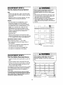
ADJUSTMENT
Adjust
the
STEP
2
Force
Without a properly installedsafety reversalsystem,
persons(particularly small children) could be
SERIOUSLY
INJUREDor KILLEDby a closing garage
door.
Force adjustment controls are located on the back
panel of the motor unit. Force adjustment settings
regulate the amount of power required to open and
close the door.
• Too much force on garagedoor will interfere with
properoperation of safety reversalsystem.
• NEVERincreaseforce beyondminimum amount
requiredto close garagedoor.
• NEVERuse force adjustmentsto compensatefor a
binding or sticking garagedoor.
• If one control (force or travel limits) is adjusted,the
othercontrol may also needadjustment.
• After anyadjustmentsare made,the safety reversal
systemMUSTbe tested. Door MUSTreverseon
contactwith one-inch high object (or 2x4 laid fiat) on
floor.
If the forces are set too light, door travel may be
interrupted by nuisance reversals in the down
direction and stops in the up direction. Weather
conditions can affect the door movement, so
occasional adjustment may be needed.
The maximum force adjustment range is about
3/4 of a complete turn. Do not force controls
beyond that point. Turn force adjustment controls
with a screwdriver.
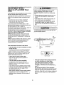
NOTE: If anything interferes with the door's upward
travel, it will stop. If anything interferes with the
door's downward travel (including binding or
unbalanced doors), it will reverse.
HOW AND WHEN TO ADJUST THE FORCES
Force Adjustment
1. Test the DOWN (close) force
• Grasp the door bottom when the door is about
halfway through DOWN (close) travel. The door
should reverse. Reversal halfway through down
travel does not guarantee reversal on a one-inch
obstruction. See Adjustment Step 3, page 30.
If the door is hard to hold or doesn't reverse,
DECREASE the DOWN (close) force by turning
the control counterclockwise. Make smag
adjustments until the door reverses normally.
After each adjustment, run the opener through
a complete cycle.
• If the door reverses during the down (close)
cycle and the opener lights aren't flashing,
iNCREASE DOWN (close) force by turning the
control clockwise. Make small adjustments until
the door completes a close cycle. After each
adjustment, run the opener through a complete
travel cycle. Do not increase the force beyond
the minimum amount required to close the door.
Back panel
2. Test the UP (open) force
• Grasp the door bottom when the door is about
halfway through UP (open) travel. The door
should stop. If the door is hard to hold or
doesn't stop, DECREASE UP (open) force by
turning the control counterclockwise. Make small
adjustments until the door stops easily and
opens fully. After each adjustment, run the
opener through a complete travel cycle.
• If the door doesn't open at least 5 feet,
INCREASE UP (Open) force by turning the
controlclockwise. Make small adjustments until
door opens completely.Readjust the UP limit if
necessary.After each adjustment, runthe
opener througha complete travel cycle.
Adjustment
29
Label
Control
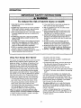
ADJUSTMENT
Test the
Safety
STEP
3
Reversal
System
Without a properly installedsafety reversalsystem,
persons (particularlysmall children) could be
SERIOUSLY
INJUREDor KILLEDby a closing garage
door.
• Safetyreversalsystem MUSTbe tested every month.
• If one control (force or travel limits) is adjusted,the
other control may also needadjustment.
• Nter ANYadjustmentsare made,the safetyreversal
systemMUSTbe tested. Door MUSTreverseon
contact with one-inchhigh object (or 2x4 laid flat) on
the floor.
TEST
• With the door fully open, place a one-inch board
(or a 2x4 laid flat) on the floor, centered under the
garage door.
• Operate the door in the down direction. The door
must reverse on striking the obstruction.
ADJUST
• If the door stops on the obstruction, it is not
traveling far enough in the down direction.
Increase the DOWN limit by turning the DOWN
limit adjustment screw counterclockwise 1/4 turn.
NOTE: On a sectional door, make sure fimit
adjustments do not cause the trolley to move
within 2-1/2" of the trolley stop bolt. If necessary
lengthen straight door arm to maintain this
minimum distance.
• Repeat the test.
• When the door reverses on the one-inch board,
remove the obstruction and run the opener through
3 or 4 complete travel cycles to test adjustment.
I
IMPORTANT SAFETY CHECK:
I
Repeat Adjustment Steps 1, 2 and 3 after:
• Each adjustment of door arm length, limits, or
force controls.
• Any repair to or adjustment of the garage door
(including springs and hardware).
One-inch board (or a 2x4 laid flat)
• Any repair to or buckling of the garage floor.
• Any repair to or adjustment of the opener.
ADJUSTMENT
Test
the
Safety
STEP
Reversing
4
Without a properlyinstalledsafety reversingsensor,
persons(particularlysmall children) could be
SERIOUSLY
INJUREDor KILLEDby a closing garage
door.
Sensor
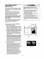
• Press the remote control push button to open the
door.
• Place the opener carton in the path of the door.
• Press the remote control push button to close the
door. The door will not move more than an inch,
and the opener light will flash.
The garage door opener will not close from a remote
if the indicator light in either sensor is off (alerting
you to the fact that the sensor is misaligned or
obstructed).
If the opener closes the door when the safety
reversing sensor is obstructed (and the sensors
are no more than 6" above the floor), call for a
trained door systems technician.
3O
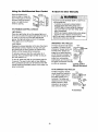
OPERATION
IMPORTANT SAFETY INSTRUCTIONS
To reduce the risk of severe injury or death:
1. READANDFOLLOWALL WARNINGSAND
INSTRUCTIONS.
2. ALWAYSkeepremote controls out of reachof children.
NEVERpermitchildrento operateor play with garage
door control push buttons or remote controls.
3. ONLYactivategaragedoor when it canbe seenclearly,it
is properlyadjusted,and thereare no obstructionsto
door travel,
4. ALWAYSkeepgaragedoor in sight until completely
closed.NOONESHOULDCROSSTHE PATHOFTHE
MOVINGDOOR.
5. If possible,use emergencyreleasehandleto disengage
trolley ONLYwhen garagedoor is CLOSED.Weak or
broken springs or unbalanceddoor could result Lnan
open door falling rapidly and/or unexpectedly.
6. NEVERuseemergencyreleasehandle unlessgarage
doorway is clear of persons andobstructions,
7. NEVERusehandleto pull garagedoor open or closed. If
ropeknot becomesuntied, you could fall.
Using
Your
Garage
Door
8. If one control (force or travel limits) is adjusted,the
other control may also needadjustment.
9. After any adjustmentsare made,the safety reversal
system MUSTbe tested.
10. Safetyreversalsystem MUSTbe testedevery month.
Garagedoor MUSTreverseon contact with one-inch
high object (or a 2x4 laid flat) on the floor.
11. ALWAYSKEEPGARAGEDOORPROPERLY
BALANCED
(seepage3), An improperly balanceddoor maynot
reversewhen requiredand could result in severeinjury
or death.
12. All repairsto cables,spring assembliesand other
hardware,all of which are under EXTREMEtension,
MUSTbe madeby a traineddoor systemstechnician.
13. ALWAYSdisconnect electricpowerto garagedoor
openerbefore makingany repairsor removingcovers.
14SAVETHESEINSTRUCTIONS.
3. If opening, the door wig stop.
Opener
4. If the door has been stopped in a partially open
position, it will close.
Your opener and hand-held remote control have been
factory-set to a matching code to operate with the
large push button. Your opener will operate with as
many as four "SRT" (Smart Receiver/Transmitter)
hand-held remote controls and one Multi-function
Keyless Entry. However, you can use either of the
two small buttons, if you prefer. And, the 3-function
remote control can also activate additional garage
door openers and/or light controls. If you purchase a
new remote, or if you wish to deactivate any remote,
follow the instructions in the Programming section.
5. if obstructed while closing, the door will reverse. If
the obstruction interrupts the sensor beam, the
opener light will blink for five seconds.
6. If obstructed while opening, the door will stop.
7. If fully open, the door wig not close when the beam
is broken. The sensor has no effect in the opening
cycle.
If the sensor is not installed, or is misaligned, the
door won't close from a hand-held remote. However,
you can close the door with the Door Control, the
Outdoor Key Switch, or Keyless Entry, if you activate
them until down travel is complete. If you release
them too soon, the door will reverse.
Activate your opener with any of the following:
• The hand-held Remote Control: Hold the large
push button down until the door starts to move.
• The wall-mounted Door Control: Hold the push
button down until the door starts to move.
The opener light will turn on under the following
conditions: when the opener is initially plugged in;
when power is restored after interruption; when the
opener is activated.
• The Keyless Entry (See Accessories): If supplied
with your garage door opener, it must be
programmed before use. See Programming,
It will turn off automatically after 4-1/2 minutes or
provide constant light when the Light feature on the
Premium Control Console is activated. Rulb size is
75 watts maximum.
When the opener is activated (with the safety
reversing sensor correctly installed end aligned)
1. If open, the door will close. If closed, it will open.
2. If closing, the door will reverse.
31
Using
the
Wall.Mounted
Press the lighted push
button to open or close the
door. Press again to reverse
the door during the closing
cycle or to stop the door
while it's opening.
Door
Control
To Open
the
Door
Manually
LIGHTEb
PUSH BUTTON
--.
!,
• To preventpossible SERIOUSINJURYor DEATHfrom
a falling garagedoor:
If possible,use emergencyreleasehandleto
disengagetrol]ey ONLYwhen garagedoor is
CLOSED.Weak or brokensprings or unbalanced
door could result in an open door falling rapidly
and/or unexpectedly.
- NEVERuseemergencyreleasehandleunlessgarage
doorway is clearof personsand obstructions.
• NEVERuse handleto pull door open or closed.If rope
knot becomesuntied,you could fall.
i LIGHT
: BUTTON
-- - LOCK
BUTTON
THE PREMIUM CONTROL CONSOLE
Light feature
Press the Light button to turn the opener light on or
off. It will net control the opener light when the door is
in motion. If you turn it on and then activate the
opener, the light will remain en for 4-1/2 minutes.
Press again to turn it off sooner.
Lock feature
DISCONNECT THE TROLLEY:
Designed to prevent operation of the door from handheld remote controls. However, the door will open
and close from the Door Control, the Outdoor Key
Switch and the Keyless Entry Accessories.
Trolley
The door should be fully closed
if possible. Pull down on the
emergency release handle (so
that the trolley release arm
snaps into a vertical position)
Trolley -.J
and lift the door manually. The Release art[
(In
Manual
lockout feature prevents the
Disconnect
trolley from reconnecting
Position)
automatically, and the door can
be raised and lowered manually
as often as necessary.
Lockout _osition
(Manual disconnect)
To activate, press and hold the Lock button for 2
seconds. The push butten light will flash as long as
the Lock feature is on.
To turn off, press and hold the Lock button again for
2 seconds. The push button light will stop flashing.
The Lock feature will also turn off whenever the SRT
(Smart Receiver/Transmitter) button on the motor unit
panel is activated.
TO RE-CONNECT THE TROLLEY:
Pull the emergency release
handle toward the opener at
a 45 ° degree angle so that
the trolley release arm is
horizontal. The trolley will
reconnect on the next UP or
DOWN operation, either
manually or by using the
door control or remote.
Trolley
_p_ulir_Yn
dn_
To reconnect
32
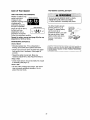
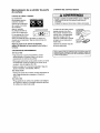
Care
of Your
THE REMOTE CONTROL BA'I'rERY
Opener
LIMIT AND FORCE ADJUSTMENTS:
Weather conditions may
cause some minor
changes in door
operation requiring some
re-adjustments,
particularly during the
first year of operation.
FORCE
CONTROLS
To preventpossibleSERIOUSINJURYor DEATH:
• NEVERallow small children near batteries.
• If batteryswallowed, immediatelynotify doctor.
The lithium battery should
produce power for up to
5 years. To replace battery,
use the visor clip or
screwdriver blade to pry open
the case as shown. Insert
battery positive side down.
LIMIT CONTROLS
Pages 28 and 29 refer to
the limit and force
adjustments. Only a
screwdriver is required.
Follow the instructions carefully.
Repeat the safety reverse test (page 30) after any
adjustment of limits or force,
MAINTENANCE
Dispose of old battery
properly.
I
I
I
I
3*FUNCTION
Open this end
_
Rrst Loavoid
_
cracking
o_
_i
_,,
Twist here
COMPAC_
to open
SCHEDULE
Once a Month
• Manually operate door. If it is unbalanced or
binding, call a trained door systems technician.
NOTICE: To comply with FCC and/or Industry Canada rules, adjustment or
the
code seHing
replacing the bakery.
ARE NOOTHERUSER
SERVICEASLEPARTS,m°dificati°ns
ofthis or
receiverand/ortransmitter
areTHERE
prohibited,exce_
fo_ changing
• Check to be sure door opens & closes fully. Adjust
limits and/or force if necessary. (See pages 28
and 29.)
• Repeat the safety reverse test. Make any
necessary adjustments. (See Adjustment Step 3.)
Twice a Year
• Check chain tension. Disconnect trolley first. Adjust
if necessary (See page 11).
Once a Year
• Oil door rollers, bearings and hinges. The opener
does not require additional lubrication. Do not
grease the door tracks.
33
Having
a Problem?
1. The opener doesn't operate from either the Door
Control or the remote control:
• Does the opener have electric power? Plug a lamp into the
outlet. If it doesn't light, check the fuse box or the circuit
breaker. (Some outlets are controlled by a wall switch.)
• Have you disabled all door locks? Review installation
instruction warnings on page 11.
• Is there a build-up of ice or snow under the door? The door
may be frozen to the ground. Remove any restriction.
• The garage door spring may be broken. Have it replaced.
• Repeated operation may have tripped the overload
protector in the motor. Wait 15 minutes and try again.
2. Opener operates from the remote, but not from the
Door Control'.
• Lsthe door control lit? If not, remove the bell wire from the
motor unit terminals. Short the red and white terminals by
touching both terminals at the same time with a piece of
wire. If the opener runs, check for a faulty wire connection
at the door control, a short under the staples, or a broken
wire.
• Are the wiring connections correct? Review Installation
Step 6, page 18.
3. The door operates from the Door Control, but not from
the remote control:
• Is the door push button flashing? If your model has the
Lock feature, make sure it is off.
• Program the opener to match the remote control code.
(Refer to instructions on the motor unit panel.) Repeat with
all remotes.
4. The remote control has short range:
• Change the location of the remote control in your car.
• Check to be sure the antenna on the side or back panel of
motor unit extends fully downward.
• Some installations may have shorter range due to a metal
door, foil backed insulation, or metal garage siding.
(Antenna Extender Kit 41A3504)
5. Opener noise is disturbing in riving quarters of home:
• if operational noise is a problem because of proximity of
the opener to the living quarters, the Vibration Isolator Kit
41A3263 can be installed. This kit was designed to
minimize vibration to the house and is easy to install.
9, The door opens but won't close:
• If the opener light blinks, check the safety reversing sensor.
See Installation Step 10.
• If the opener light doesn't blink and it is a new installation,
check the down force. See Adjustment Step 2, page 29.
For an existing installation, see below.
Repeat the safety reverse test after the adjustment is complete.
10. The door reverses for no apparent reason and opener
light doesn't blink:
• Is something obstructing the door? Pull the emergency
release handle. Operate the door manually. If it is unbalanced
or binding, call a trained door systems technician.
• Clear any ice or snow from the garage floor area where
the door closes.
• Review Adjustment Step 2 on page 29.
• If door reverses in the fully closed position, decrease the
travel limits (Adjustment Step 1).
Repeat safety reverse test after adjustments to force or travel
limits. The need for occasional adjustment of the force and
limit settings is normal Weather conditions in particular can
affect door travel.
11. The door reverses for no apparent reason and opener
light blinks for 5 seconds after reversing:
• Check the safety reversing sensor. Remove any obstruction
or align the receiving eye. See Installation Step 10.
12. The opener light doesn't turn on:
• Replace the light bulb5 (75 watts maximum). Use a standard
neck garage door opener bulb if regular bulb bums out.
13. The opener lights don't turn off:
• Is the Light feature on? Turn it off.
14. The opener strains or maximum force is needed to
operate door:
• The door may be out of balance or the springs may be
broken. Close the door and use the emergency release
handle to disconnect the trolley. Open and close the door
manually. A properly balanced door will stay in any point of
travel while being supported entirely by its springs, if it
does not, disconnect the opener end call e trained door
systems technician. Do not increase the force to operate
the opener.
15. The opener motor hums briefly, then won't work:
• The garage door springsmay be broken. See above.
• If the problem oocurs on the first operationof the opener,
door may be locked. Disable the door lock. If the chain was
removed and reinstalled, the motor may be out of phase.
Remove the chain; cycle the motor to the down position.
Observe the drive sprocket. When it turns in a clockwise
direction and stops in the down position, reinstall the chain.
Repeat the safety reverse test after the adjustment is
complete.
6. The garage door opens and closes by itself:
• Be sure that all remote control push buttons are off.
• Remove the bell wire from the door control terminals and
operate from the remote only. If this solves the problem, the
door control is faulty (replace), or there is an intermittent short
on the wire between the door control and the motor unit.
• Clear memory and re-program all remote controls.
7. The door doesn't open completely:
• Is something obstructing the door? Is it out of balance, or
are the springs broken? Remove the obstruction or repair
the door.
• If the door is in good working order but now doesn't open
all the way, increase the up force. See Adjustment Step 2.
• If the door opens at least 5 feet, the travel limits may need
to be increased. One turn equals 2 inches of travel. See
Adjustment Step 1.
Repeat the safety reverse test after the adjustment is
complete.
8. The door stops but doesn't close completely:
• Review the travel limits adjustment procedures on page 28.
Repeat the safety reverse test after any adjustment of door
arm length, close force or down limit.
16. The opener won't operate due to power failure:
• Use the emergency release handle to disconnect the
trolley. The door can be opened and closed manually.
When power is restored, press the Door Control push
button and trolley will automaticaUy reconnect (unless
trolley is in lockout position.) See page 32.
• The Emergency Key Release accessory (for use on
garages with no service door) disconnects the trolley from
outside the garage in case of power failure.
17. The chain droops or sags:
• It is normal for the chain to droop slightly in the closed door
position.Use the emergency release to disconnectthe
trolley.If the chain returns to normal height when the troney
is disengaged and the door reverses on a one-inch board,
no adjustments are needed (see page 11).
34
PROGRAMMING
Your garage door opener has already been programmed at the factory to operate with your hand-held remote
control. The door will open and close when you press the large push button.
Below are instructions for programming your opener to operate with additional "SRT" remote controls.
To Add an Additional
USING THE "LEARN"
Hand.held
Remote
Control
BUTTON
[]
1. Press and release the "learn"
button on the motor unit. The
learn indicator light will glow
steadily for 30 seconds.
2. Within 30 seconds, press and
hold the button on the hand-held
remote* that you wish to operate
your garage door.
3. Release the button when the
motor unit lights blink. It has
learned the code. If light bulbs are
not installed, two clicks will be
heard.
To Erase
All Codes
From
Unit Memory
\1/
*3.Function
Motor
Remotes
If supplied with your garage door opener, the large
button is factory programmed to operate it. Additional
buttons on any "SRT"
3-function remote or
___
..7_
compact remote can be
programmed to operate
other "SRT" garage door
openers.
To deactivate any unwanted remote, I_
first erase all codes:
Press and the hold "learn" button on
motor unit until the learn indicator
light goes out (approximately 6 seconds). All previous
codes are now erased. Reprogram each remote or
keyless entry you wish to use.
35
To Add
or Change
a Keyless
Entry
PIN
Note: Your new Keyless Entry must be programmed to operate your garage door opener.
USING THE "LEARN" BUTTON
1. Press and release the "learn"
button on motor unit. The learn
indicator light will glow steadily for
30 seconds.
2. Within 30 seconds, enter a four
digit personal identification
number (PIN) of your choice on
the keypad. Then press and hold
the ENTER button.
3. Release the button when the
motor unit lights blink. It has
learned the code. If light bulbs
are not installed, two clicks will
be heard.
\1
/
To change the code in your Keyless
Entry at any time, repeat Steps 1-3.
To ensure that your hand-held
remote control codes were not
disturbed while you were
programming the Keyless Entry, test
your remotes and reprogram them if
necessary.
36
REPAIR
Rail
PARTS
Assembly
Parts
4
KEY PART
NO. NO.
3
1
2
3
4
5
6
7
8
7
Installation
DESCRIPTION
1A995
Master link kit
41C5141-1
183C158-3
183C157-3
144C56
41A5249
Complete trolley assembly
Rail- front (header) section
Rail - center/back section (2)
Chain idler pulley
Chain and cable
144C62
12D598-1
Spreader (2)
U bracket
Parts
KEY
NO.
,,o
PART
NO.
DESCRIPTION
1
2
3
41A4166
41A4884
41A4873
4
5
6
7
8
9
10
10A20
29B137
31D431
31B430
10A2
41A2828
217A238
11
12
13
14
15
16
12B590
41A5047
178B35
178B34
12B350
41A5034
Header bracket w/clevis pin & fastener
Door bracket w/clevis pin & fastener
Curved door arm section
17
41A5266-1
Safety sensor bracket
Not shown:
Assy & Installation hardware bag
(see page 7)
Owner's manual
41A5258
114A2399
37
Door control button
Premium control console
3-function remote control case
(no circuit board)
3V 2032 Lithium battery
Visor clip
Keyless entry keypad cover
Keylese entry battery cover
9 Volt battery
Emergency release rope & handle assy.
2-Conductor bell wire: white &
white/red
Straight door arm section
Hanging brackets
Safety sensor kit: receiving and
sending eyes with 3' 2-conductor bell
wire attached
Motor
Unit
Assembly
Parts
I
19
18
17
16
Brown
13
15
(Down)
LIMIT SWITCH
Contact
ASSEMBLY
14
12
Grey
Wire
Drive
Gear
Contact
KEY
NO.
PART
NO.
1
2
31D380
41C4220A
Contact
Wire
KEY
NO.
PART
NO.
Sprocket cover
Gear and sprocket assembly
Complete with: Spring washer,
Thrust washer, Retaining ring,
Bearing plate, Roll pins (2),
Drive gear and worm gear,
11
41D3058
12
41D0328-4
Universal replacement motor &
bracket assembly
Complete with: Motor, worm,
bracket, bearing assembly,
RPM sensor
Cover
13
14
41A2818
41D3452
Helical gear & retainer w/grease
Limit switch assembly
15
16
41C4398A
41 C4246
RPM sensor assembly
Wire harness assembly w/plug
DESCRIPTION
DESCRIPTION
3
41A2817
4
41 B4245
Helical gear w/retainer and
grease
Drive/worm gear kit w/grease
Roll pins (2)
Line cord
5
41A4352
End panel w/all labels
17
41A2826
Shaft bearing kit
6
7
175B88
108D58-2
Light socket
Lens
18
19
41A2822A
41A4315-7E
Interrupter cup assembly
Receiver logic board assembly
8
9
10
30B363
12A373
41A3150
Capacitor - 1/2 HP
Capacitor bracket
Terminal block w/screws
20
41A3691
End panel
NOT SHOWN
Opener assembly hardware kit
(includes screws not designated
by a number in illustration).
41A2825
38
ACCESSORIES
139.53702
f
139.53703
Emergency Key Release:
Required for a garage with NO
access door. Enables homeowner
to open garage door manually from
outside by disengaging trolley.
139.53879
Outdoor Key Switch:
139.53859
Includes visor clip.
Operates the garage door
automatically from outside when
remote control is not handy.
53724
8 Foot Rail Extension:
10 Foot Rail Extension:
139.53876
Multi-Function Keyless Entry:
Enables homeowner to operate
garage door opener from outside by
entering a password.
139.53709
Door Clearance Brackets:
(For Sectional Doors Only)
Replaces top brackets and rollers on
door to reduce height of door travel,
For use when installing opener in
garage with low headroom clearance.
To allow an 10 foot door to open
fully.
53589
Compact 3-Function Remote
Control:
With loop for attaching key ring.
To allow an 8 foot door to open
fully.
53725
3-Function Remote Control:
41A5281
Support Brackets:
For finishedceilings or where
additionalsupport is required, based
on garage construction.Includes
brackets and fastening hardware.
Extension Brackets:
(Available only through Sears
Parts & Service)
(Optional) For safety sensor
installation onto the wall or floor,
WARRANTY
SEARS WARRANTY
FULL 90-DAY WARRANTY ON GARAGE DOOR OPENER
For 90 days from the date of purchase, Sears will repair this Garage Door Opener, free of charge, if defective in material or workmanship.
LIMITED WARRANTY
From the 91st day until one year from the date of purchase, Sears will furnish replacement parts for any defective parts, free of charge.
You pay for labor.
LIMITED WARRANTY ON MOTOR
1i2HP MOTOR: After 1 year and through 5 years, if the motor on this Garage Door Opener is defective, Sears will furnish a
replacement motor, free of charge. You pay for labor.
LIMITATION ON LIABILITY
SEARS WILL NOT BE UABLE FOR LOSS OR DAMAGE TO PROPERTY OR ANY INCIDENTAL OR CONSEQUENTIAL LOSS OR
EXPENSE FROM PROPERTY DAMAGE DUE DIRECTLY OR INDIRECTLY TO THE USE OF THIS PRODUCT. Some states do not
allow the exclusion or limitation of incidentalor consequential damages, so the above limitationor exclusion may not apply to you.
This warranty does not cover light bulbs or repair parts necessary because of operator abuse or negligence, including the failure to
install, adjust and operate this garage doer opener according to instructions contained in the owner's manual.
WARRANTY SERVICE IS AVAILABLE BY CONTACTING THE NEAREST SEARS SERVICE CENTER IN THE UNITED STATES.
This warranty applies only while this product is in use in the United States,
This warranty gives you specific legal rights, and you may also have other rights which vary from state to state.
Sears, Roebuck and Co., Dept. 817WA, Hoffman Estates, IL 60179
39
CONTENIDO
Introducci6n
2-7
Sujete la m_nsula de la puerta .................................
24-25
Revisi6n de los simbolos de seguridad ........................... 2
Conecte el brazo de la puerta al trole ...................... 26-27
Preparacibn de la puerta de su cochera ......................... 3
Herramientas necesarias .................................................
3
Ajustes
Planificaci6n
.................................................................
4-5
28.30
Ajuste er Iimite del recorrido ..........................................
28
Ajuste la fuerza ..............................................................
29
Inventario de las cajas de cartSn .....................................
6
Inventario de piezas .........................................................
7
Pruebe el sistema de reversa de seguridad .................. 30
Pruebe el sensor del sistema de
reversa de seguridad ...................................................
30
8
Operaci6n
Montaje
8.11
Montaje el riel y instale el trole ........................................
31.34
Sujete el riel al motor e instale el trole Ioco ..................... 9
Instrucciones de seguridad para la operaciSn ............... 31
Instale la cadena o cable y coloque la cubierta
de la polea ...................................................................
Como usar el abridor de la puerta de su cochera ........ 31
10
Apriete la cadena ...........................................................
11
Instalaci6n
11.27
Como usar la unidad de control de pared ..................... 32
Como abrir la puerta manualmente ............................... 32
Mantenimiento
de su abridor de puerta de cochera......33
Instrucciones de seguridad para la instalaci6n .............. 11
Determine dSnde va a instalar
la mensula del cabezal ...........................................
12-13
Si tiene algen problema? ...............................................
Instale la mensula del cabeza] ......................................
14
Como usar un control remoto de mano ......................... 35
Coloque e] riel en la m_nsula del cabezal ..................... 15
Como borrar todos los cedigos ...................................... 35
Controles remotos de tres funciones ............................. 35
Coloque el abridor .........................................................
16
Cuelgue el abridor .........................................................
17
C6mo
programar
el abridor
34
35-36
Como afiadir o modificar un c6digo
de entrada sin Ilave .....................................................
36
Instale la consola de control premium ........................... 18
Instale la luce y la lente .................................................
19
Instale la manija y la cuerda de emergencia ................. 19
Requisitos para la instalaci6n electrica ......................... 20
Instale el sensor del sistema
reversa de seguridad ..............................................
Accesorios
37
Garantia
37
Nbmeros
de Servicio
Contra
tapa
21-23
INTRODUCCION
Revisi6n
de los simbolos
de seguridad
y t_rminos
Este abridor de puerta de cochera ha sido disefiado para un funcionamiento seguro, siempre y cuando se insta[e, se
pruebe, se opere y se le de mantenimiento como se indica a Io largo de este manual, cumpliendo al pie de ta letra
con todas las advertencias e instrucciones generales aquf contenidas.
Mecdnica
El_ctrica
Estas advertencias y/o sfmbolos de seguridacl que
aparecen a Io largo de este manual le alertar&n de que
existe el riesgo de una lesion seria o de muerte si no
se siguen las instrucciones correspondientes. El peligro
puede ser eldctrico (electrocucien) o mecanico. Lea las
instrucciones con mucho cuidado.
Cuando vea esta palabra y/o simbolo de seguridad a Io
largo de este manual le alertar& de que existe el riesgo
de dafiar la puerta de la cochera y/o el abridor si no se
siguen las instrucciones correspondientes. Lea las
instrucciones con mucho cuidado.
Preparaci6n
• Desarme
de la puerta
de su cochera
las cerraduras.
• Retire cualquier cuerda o cable que este conectado a
la puerta.
• Haga la sigulente prueba con su puerta para
verificar que est6 equilibrada y que no se atore ni se
pandee:
1. Levante la puerta hasta la mitad de su recorrido
como se muestra. Suelte la puerta 6sta debera
mantenerse en esa posici6n con s61oel soporte de
los resortes.
2. Suba y baje la puerta; observe si se atora con algo
o si se pandea.
ParaevitarunaLESIONGRAVEE INCLUSOLA MUERTE:
• SIEMPREIlamea un t6cnico profesional para que lede
servicio a su puerta de cocherasi 6sta se atora, se pan{lea,o
est;_desequilibrada. Unapuerta de cocheraque no est6bien
equilibradapuedeno retrocedercomo se requiere.
• NUNCAintente aflojar,mover ni ajustar la puertade su
cochera,los resortesde la puerta, loscables,laspoleas,las
rnensalasni la tornilleria, pues todos estos elementosest_n
bajo tensi6n EXTREMA.
• QuitarTODOSlossegurosy retirarTODAS[ascaerdas
conectadas
a la puertade eocheraANTESde instalary operar
el abridorde la puertade cocherapara evitarque se enreden.
Si su puerta se atora o se pandea, Ilame a un t6cnico
especializado en sistemas de puertas.
Paraevitardanesa la puertay al abridor:
• SIEMPREdesarrnelas cerradurasantesde insta]ary/o de
operar el abridor.
• SOLAMENTE
opereel abridor de puertade cocheracon
corrientede 120V 60 Hz con objeto de evitarsu real
funcionamientoy que el abridor se dane.
Puerta seccional
Puerta de una sola pieza
Herramientas
necesarias
Durante el montaje, instalaci6n y ajuste del abridor, las
instrucciones le indicar_ln usar las herramientas que
aparecen en la siguiente ilustraci6n.
-'-
b
yB_/c3a2Sdep3u/l'tc
6adea/16
Escalera
UO
L/_6y 114de puleada'
_
_-'_.
Desarmador,
Pinzas con
-- seguro
destomillador
Llave ,nglesa
_,Hay otra puerta que de acceso ala cochera? Si no
es asi, sere necesario contar con el sistema de [lave
de emergencia Modelo 53702. Vea la pegina de
Accesorios.
Planificacien
Identifique la altura y el tipo de su puerta de cochera.
Revise el area de su cochera y observe si aiguna de
las siguientes instalaciones corresponden ala suya.
A veces se requieren matedales adicionales, asi que tal
vez sea conveniente tener esta hoja y las ilustraciones
correspondientes ala mano cuando inicie la instalacien
de su abridor.
Observe el punto donde la puerta hace contacto con
el piso. El espacio entre la base de [a puerta y el piso
no debe exceder 0.625 cm (1/4 de pulgada). Si no es
asi, se corre el riesgo de que el sistema de reversa
de emergencia no funcione correctamente. Vea
Ajustes, Paso 3. Va a ser necesario reparar ya sea el
piso o la puerta.
Dependiendo de sus necesidades individuales, es
posible queen algunos casos vaya a necesitar
materiales o herramientas que no se incluyen con este
producto.
• [nstalaci6n Paso 1 - Observe la pared o el cielo raso
justo arriba de la puerta de la cochera. La mensula
del cabezal debe de estar firmemente sujeta a los
soportes de la estructura.
• instalaci6n Paso 5 - Si el plafen o cielo raso de su
cochera tiene acabados, es posib]e que necesite una
mensula de soporte y/o mas pernos y tornilleria para
la instalacien.
INSTALACION
CON UNA PUERTA SECCIONAL
Si tiene una puerta de aluminio, fibra de vidrio, o con
paneles de vidrio, va a necesitar refuerzos verticales
y horizontales en la puerta. (Instalacien, Paso 11).
El abridor se debe instalar arriba del centro de la
puerta, pero si existe algL_nresorte de tensien o placa
de apoyo en el paso de la mensula del cabezal, se
puede instalar hasta a 1.20 m (4 pies) ala derecha o a
la izquierda del centro de la puerta. Vea Instalacien,
Pesos 1 a111.
• Instalaci6n Paso 10 - Dependiendo del tipo de
construcci6n de su cochera, es posible que necesite
m_nsulas de extensien o bloques de madera para
instalar los sensores.
Si su puerta es de mes de 2.10 m (7 pies) de altura,
vea Extensiones de riel en la Secci6n de Accesorios.
• Instalaci6n Paso 10 - El montaje al ras del piso del
sensor que activa el sistema de reverse de seguridad
podria requerir piezas que no se incluyen,
INSTALACION
CON UNA PUERTA
SECCIONAL
ClELO RASO CON ACABADOS
Se requiere rn nsula de
soporte y tornilioso
sujetadores Vea lap gina 17,
Los refuerzos verticales y
necesados papa tas puerlas de cochera de
materiales m s livianos (fibre de vidtio, acero,
aluminio, o puertas con paneles de viddo).
Vea lap gina 24. donde eneontrar m s detalles.
Riel
Pared delantera
Unidad
del motor
Resorte de extensi n
O
F_esortede torsi n
LJnidad de
control dl
la puerta,
instalada
en la pan
i
Pueda
aceeso
r
Sensor
El espacio
Sensor del sistema
de reversa de seguridad
entre la base
de
de
M_nsula
delcabezaI
Perno de
del_ole
EN POSICI(_N CERRADA
Trole
del sistema
del sistema
de reverse
de
liberacion
de seguridad
de emergencia
la puerta y el piso no debe de
exceder 0.625 cm (1/4 de pulg.).
Mensula
de la
puerta
la puerta
curvo
Planificaci6n
INSTALACION
(continba)
CON PUERTAS DE UNA SOLA PIEZA
Sin un sistemade reverse deseguridad quefuncione
debidamente,al cerrar lapuerta de la eocherase correel
riesgode que las personas(yen particular los ni_os
pequeSos)sufran LESIONESGRAVESe INCLUS0LA MUERTE.
• El espacioentre la basede la puerta de la cocheray el piso
NO DEBEexceder0.625 cm (1/4 de pulgada).Deno ser asi,
el sistemade reverse de seguridad no va a funcionar
debidamente.
• Generalmente una puerta de una sole pieza no
requiere de refuerzos adicionales. Si usted tiene una
puerta de material ]iviano y quiere reforzada, consulte
la informacibn respecto a puertas seccionales,
contenida en InstalaciSn, Paso 11.
• Dependiendo del dise5o de su puerta, tel vez
necesite piezas o sujetadores adicionales pare la
mensula de la puerta (Paso 11).
PUERTA DE UNA SOLA PIEZA
SIN CARRIL
• El piso o la puerta de lacocheraSE DEBErepararpare
eliminar este espaci0.
ClELO RASO CON ACABADOS
Se requiere mdnsula de soporte
y tornillos o sujetadores.
Vea la pagina 17.
Pared delantera
I
i
Unidad det motor
Rie[
Unidad de control de la puerta,
instalada en la pared
I
Puerta
_cceso
de
J
_
[_]
Perno
de paroEN
POS'CI_N
del trole
cERRADA
Cable
Trole
o
I
Sensor del sistema de
reverse de seguddad
r delsisten de
reverse de seguddad
El espacio entre la base de
la puerta y e] piso no debe de
exceder 0.625 cm (1/4 de pulg.).
Cuerda y man_ja
la puerta
dp_
P arazo de
i_'_
PUERTA
de la
emergencla
Srazo _
puerta
liberaci6n de
_recto
la cochera
DE UNA PIEZA CON CARRIL
EN POSICION CERRADA
Pernode paro
Cable
Cadena
Riel
Brazo de
[a pue_a
recto
lacochera
_
Sensor del sistema de
reverse de seguridad
Elpisodebeestarnivelado
rS'eSvteema
de se gutided
a todo Io ancho de la puerta
Cuerda y manija
del sistema de
e emergencia
Inventario
de las cajas
Su abridor viene empacado en una caja de cartSn que
contienen el motor y las piezas que se muestran en la
siguiente ilustracion. Tome nota de que los accesorios
van a depender del modelo que haya comprado. Si falta
alguna pieza, revise con cuidado el material de
empaque ya queen ocasiones las piezas se atoran en
Modelo 53971
Modelos 53960,53968,
el hule espuma. Toda la tornilleria y las piezas
necesarias para el montaje e instalacion de su puerta
se ilustran en la siguiente pagina. Conserve la caja y
los materiales de empaque (hule espuma) hasta que la
instalaciSn y el ajuste se hayan terminado.
Modeios 53960 (1), 53968 (2),
53970 (1), 53971 (2), 53973 (1)
Modelos 53970 (1), 53973 (1)
Control remote compacto
de 3 funciones
53970,
5393
Control remote de tres funciones,
con clip para el visor (2)
Unidad de control Premium
Botbn de control de la puerta
Modelo 53973
Lente par la luz
Trole
,
©
y posterior del del
Cubierta de la polea
Entrada sin Ilave
de funciones m_ltiples
Polea de la cadena
;,,
M@nsulas
Section delantera
del 6el (cabezal}
Mensula de la puerta
para colgar
J
Secci6n curva del
braze de Ja puerta
Mensula del cabezal
Dos cables conductores
de campana. Blanco y blanco/rojo
Dos m_nsulas para el sensor
del sistema de reversa de segutidad
reversa de segur_dad(un ojo transmisor
y un ojo receptor) conectados a un cable
de campana de dos conductores.
Blanco y blanco y negro
Etiquetas de
seguridad y
literatura
Secci6n recta
del braze de
la puerta
Inventario
de piezas
Antesde la instalacibn, organice todas las piezas en grupos come se muestra en la siguJenteiJustraci6n,
TORNILLERiA
@
Y PIEZAS PARA EL ARMADO
© ©©
Tuefca de
1/4-20 (2)
Desplegador de la cadena (2)
8
Roldana de
3/0 pulg, (1)
Tuerca de
3/0 pulg. (1}
J
i
)@@)))
Perno de
1/4-20xl-314
pulg.(2)
Enlace maestro (2)
Pemo Ic_o (1)
Flecha _scada deltrole(1)
TORNILLERiA Y PIEZAS PARA LA INSTALACION
AsP O
Perno de
1/4-20xl/2
pulg. (2)
Tuerca de mariposa
1/4-20 (2)
Anillo sujetador (3)
Tom/lie de cabeza hexagonal
de 5116-18x7/8 pulg. (4)
_]
©
Tuerca de
5/16-18 pulg (8)
Roldana de 5/16 pulg (7)
Illlll'tLIDILlllllllll>
pulg. (2)
Grapas con
matehal aislante
(30)
_] IIIIltlllllllllllllil
Tomillo de cabeza cuadrada
de 5/16-18xl-7/8
Manija
Torn/lie 6ABx1-1/4 pulg. (2)
Tornillo de 6-32xl pulg. (2)
(_lltlll!llll!lLIIIIIllllllllllllllllB
Perno de 5116-18x2-112 pulg, (2)
Pasador de chaveta
de 5/16x1*112 putg (1)
Taquetes para inure false (2)
Pasador de chaveta
de 5/16x1-1/4 pulg. (1)
J
Cuerda
Espaciador (2)
Pasador de chaveta
de 5/16xl pulg. (1)
MONTAJE,
PASO 1
Monte el riel e instale el trole
No encienda ni use el abridor hasta que Ilegue al paso
de la instalacibn correspondiente, de otra rnanera
oorre el riesgo de complicar el proceso de instalaci6n.
El riel delantero tiene una '_entana" cortada en el extremo
de la puerta (yea la ilustracion). El orificio que se
encuentra arriba de esta ventana es m_s grande en la
parte superior del riel queen/a parte inferio_ Hay un
orificio mas pequefio que se encuentra a 8.75 ¢m (3-1/2
pulg.) y est& cerca de la orilla del rieL Gire el riel posterior
de manera que tenga un orificio similar cerca de la orilla
opuesta, mas o menos a 11.87 cm (4-3/4 pulg.) del
extremo. Un riel de tres partes utiliza dos rieles posteriores
1. Quite el brazo recto de la puerta y el pasador de
chaveta que viene empacado dentro del riel delantero y
pongalo a un lado para usado en la Paso 12 de la
Instalacibn.
2. Alinee las secciones del riel sobre una superficie plana
exactamente como se indica y luego deslice los
extremos m_,s pequeSos dentro de los mas grandes.
Las pestafias que se encuentran a Io largo de los lados
de[ riel se van a ajustar en su lugar.
3. Coloque el motor sobre el material de empaque para
proteger la cubierta del mismo y apoye el extremo
posterior del riel encima. Para que le resulte mC,s
c6modo, ponga algL_ntipo de apoyo bajo el extremo
delantero del riel.
4. Ponga en el riel una pinzas con seguro como tope
temporal del trole a 20 cm (8 pulg.) del centro del orificio
de la poiea Ioca, como se indica en la ilustraci6n.
5. Revise y cerci6rese de que haya 4 cojinetes de
desgaste dentro del trole interno, estos cojinetes son
negros y de plastieo. Si los cojinetes se han soltado
durante el transporte, revise todo el material de
empaque. Ponga los cojinetes de desgaste en su lugar
como se indica.
6. Conecte los troles intemo y externo como aparece en la
ilustraci6n.
7. Deslice el trole a Io largo del riel desde el extremo
posterior hacia las pinzas.
Trole
pequefio
/
lieles posteriores
(AL MOTOR)
Extremo rnas
pequeAo
Trole
Dis tanc_a de20 cm (8 pul
externo
- Pestafias
de la potea Ioca
Pinzas con seguro
T_oleinterno
la polea Ioca
_
Ventana
Ventana
Riel delantero
(A LA PUERTA)
Cojinetes de desg_ste
MONTAJE,
PASO 2
Sujete
al
el
riel
PRECAUCI6N
motor
• Coloque un perno de 1/4-20xl-3/4 de pulg. dentro del
orificio de la cubierta de proteccibn que se encuentra en
el extremo posterior del riel, como se indica en la
ilustracibn. Apriete bien el perno con con tuerca de
1/4-20 de pulg.
Uses61010st0rnill0s quevienenmontados en la partesuperior
del abrid0r paraevitarque el abridor de la puertade c0cherase
I dafieseriamente.
• Ponga la mensula en 'U' sobre el motor con el lado
piano hacia abajo y alinee los orificios de la m_nsula
con los orificios de los tornillos. Sujete con los tomillos
que quit5 antes.
I
Tornillos
• Quite los dos tornillo de la parte superior del motor.
• Coloque los desplegadores en la mensula en 'U'.
Escuchar& un chasquido cuando quedan en su lugar.
Polea del motor
M_nsula en 'U'
Perno
Ofificio
pafa
el pefno
en
• Alinee el riel con la parte superior del motor. Deslice el
extremo del riel en la mensula en 'U', hasta los topes
que sobresalen en la parte superior y a los lados de la
m_nsula.
OESLICE EL REL HASTA
LOS TOPES QUE ESTAN EN
LA, PARTE SUPERIOR Y A LOS
LADOS DE LA M_NSULA
I Tuerca
ESTAS PIEZAS SE MUESTRAN
EN SU TAMAI_O NORMAL
Enganche
el desplegador
en las ranuras
posteriores, luego
coloque las pesta_as
dentro de la
ranuras delanteras.
_/..__=, _
))))))))))))
T.0,00,0
Pern0 de 1/4-20xl-3/4 de pulg.
MONTAJE,
Instale
PASO
la polea
1/4-20 de pulg.
3
Cadena y
cable
Ioca
• Acomode la cadena o cable a un ]ado del riel, como se
ilustra. Tome el extremo del cable que tiene una lazada
y pase aproximadamente 30 cm (12 pulg.) de cable a
traves de la ventana. Deje el cable colgando hasta Ilegar
al Paso 5 de Montaje.
• Retire la cinta de la polea Ioca. El interior del centro debe
estar engrasado. Si se ha secado, vuelva a engrasarlo
para asegurar que la operacibn sea adecuada.
• Coloque la polea Ioca dentro de la ventana como
aparece en la ilustraci6n.
• Inserte el perno Ioco desde la parte superior y a traves
del riel y la polea. Apriete con una roldana y una tuerca
de 3/8 de pulg. por debajo del riel hasta que la roldana
quede comprimida.
• Haga girar la polea para cerciorarse de que da vuelta
libremente.
paro del tmle :
de {a polea
Engrase
el interior_
Polea Iota
Roldana de
i
3/8 de pulg _i)
• Pase on perno de 1/4-20xl-3/4 de pulg por el orificio de
paro del trole que se encuentra en la parte de]antera del
riel, como aparece en la ilustracion.Apriete bien con una
tuerca de 1/4-20 de pulg.
LazaOa
del cable
Perno de 1/4-20xl -3/4 de pulg
i
Polea
Io:;a
_--Tuercade
i
3/Sde pulg
©
ESTAS PIEZAS SE MUESTRAN EN SU TAMAI_IO NORMAL
PernoIoco
I
Tuercade
1/4-20 de pulg
Tuerca de
3/8 de putg.
Ro]danade
3/8 de pulg.
MONTAJE,
Instale
PASO 4
la cadena
la cubierta
de
o cable
y coloque
Paraevitar posibles lesi0nesgravesen los dedos causadaspot
las partesm6viles del abrid0r de puenade c0chera:
• SIEMPREtenga [as manos lejosde la polearnientras este
funcionandoel abridor,
• Pongala cubierta de la poleaANTESde hacer funci0nar
el abridor.
la polea
1. Jale el cable alrededor de la polea Ioca y hacia el trole.
2. Conecte la lazada del cable a la ranura de retenci6n del
trole, como aparece an la ilustracion:
• Empuje los pernos de la barra de enlace maestro
desde abajo hacia arriba y p_selos a traves de la
lazada del cable y la ranura del trole.
• Empuje la tapa del enlace maestro sobre los pernos y
las ranuras de los pernos.
CartOn para alimentar
el cable/cadena
• Deslice el resorte de clip sobre la tapa y sobre las
ranuras de los pernos hasta que los dos pernos est6n
bien colocados y seguros en su lugar.
Deje la cadena y
el cable dentro del cartbn
para evitar que se tuerza.
3. Con el trole contra las pinzas, alimente el resto del
cable o cadena a Io largo del riel, hacia el motor y
alrededor de la polea. Los dientes de la polea deben
engancharse en la eadena.
4. Revise para cerciorarse de que la cadena no este
torcida, luego conectela a la flecha roscada con el
enlaee maestro restante.
5. Enrosque la tuerca interna y la roldana en la flecha del
trole.
Mientras alimente la cadena y
el cable debe mantenerlos tensos
6. Pase la flecha roscada del trole a traves del orificio qua
tiene el trole. CerciSrese de que la cadena no est6
torcida.
7. Ponga la tuerca externa en la flecha del trole, dejandola
floja.
8. Quite las pinzas con seguro.
9. Alinee las pesta_as de la cubierta de la polea con las
ranuras de ]a placa de montaje. Optima la cubierta e
inserte las pestaSas en las ranuras.
i
i
,
I
i
Resorte de clip _
del enlace maestro;!,
Tapa de{
enlace maestro
Tapa del
eNSac6 maestro
Lazada
del cable
Polea
Iota
Flecha
roscada
_ ,
', _
Indentaci6n
delpemo
deltrole
_
,_
earra del
enlace
maestro
redondo
i
:
Cai01e
_
Barra del
enlace
maestro
de
la polea
Cubierta
i
Ranura
pestaSa
de _a
delantera
,,
i
Polea del motor
Ranura de la
pestaha posterior
Placa de
rnontaje
MONTAJE,
Apriete
PASO 5
la cadena
Figure
• Gire la tuerca interna y ajuste la roldana; baje ambas por
la flecha roscada, alejandolas del trole.
• Para apretar la cadena, gire la tuerca extema en la
direccibn que se indica en la Figura 1.
• Una vez que la cadena este aproximadamente 1.25 cm
(1/2 pulg) arriba de la base del riel en su punto medio,
vuelva a apretar la tuerca interna para asegurar el ajuste.
Si la cadena queda demasiado floja la polea puede hacer
ruido.
1
Tuerca
Flecha
exlerna Roldana def Vole
Para apretar
+1 /
_+
Para
na
_ercaapretar
interna
Figure 2
Una vez terminada la instalacibn, es posible que observe
que la cadena cuelga un poco cuando la puerta esta
cerrada, pero esto es normal Si la cadena regresa a la
posici6n que se ilustra en la Figura 2 cuando la puerta
est& abierta, no vuelva a ajustar la cadena.
Cadena
i
,,
I
II
II
II
II
II;It
II
'I
1
,'
I
NOTA: En el futuro, cuando le de mantenimiento
SIEMPRE jale la manija de emergencia para desconectar
el trole antes de ajustar la cadena.
Base del riel
II
f+
If
1/2 pulg.
Mitad del riel
NOTA: Es posible que la cadena se afloje despu_s del
Paso 3 de Ajustes (Pruebe el Sistema de reversa de
seguridad). Verifique que la tensi6n sea la debida y
reajuste la cadena si es necesario. Luego repita el Paso 3
de Ajustes.
Ya termin6 de armar su abridor de puerta de cochera,
por favor lea les siguientes advertencias antes de
continuar a la Secci6n de instalaci6n:
INSTALAClON
INSTRUCCIONES
MUY IMPORTANTES
PARA LA INSTALACION
Para reducir el riesgo de una lesibn grave o la muerte:
1. LEAY SIGAAL PIE DE LA LETRATODASLAS
INSTRUCClONES
PARALA INSTALACION.
2. [nstaleel abndor de puertade cocheras61osi la puertade la
cochera est_debidamenteequilibraday lubricada.Si la puerta
no est_ debidamenteequilibrada es posibleque no retroceda
cuandoas{ se requiere,cuando asi se requiere,Io quepodria
ocasionaruna lesi6n grave e incluso la muerte+
3. Todaslas reparaeionesde los cables,resortes y otras partes
]as DEBEIlevar a caboun tecnicoespecializadoen sistemas
de puertas,antes deinstalar el abridor.
4. Desarmetodos los segurosy retire todas lascuerdas
oonectadasa la puerta de la cocheraantesde instalar el
abridor con el objeto de evitar que se enreden.
5. lnstale el abridor de la puertade cochera a ueadistanciade
2.10 rn (7 pies) de1piso.
6. Monte lamanija de liberaci6nde emergenciaa unadistancia
de 1.80 rn (6 pies)del piso.
7. NUNCAconecteel abddorde la puertade cocheraa ueafuente
de energiael_ctricahastaqueasise indique.
8. NUNCA]leve puestosre]ojes,anillos ni prendasmuy flojas
mientras est_instalandoo dandoservicio al abddor,pues
podrfan atorarseen la puertade lacocherao en los
mecanismosdelabridor.
9. Instaleel control de paredde la puertade cochera:
• de maneraque quedea la vista desdela puertade
la cochera
• fueradel alcancede los niBosy a unaaltura minima de 5
pies
• lejos de todas laspartesm6vilesde la puerta.
10. Coloquelacalcomaniaqueadviertesobreel riesgodeenredarse
cercadelcontroldelapuertade lacochera,enlapared.
11. Coloquela caicomania quecontienela pruebade reversade
seguridady Iiberaci6nde emergenciaa plenavista en la
parteinterior de la puertade lacochera.
12. ALconcluir lainstalaci6n,pruebe elsistema de reversade
seguridad.La puerta DEBEretrocederal entrar en contacto
conun objeto de 2.5 cm (1 pulg.) o bien con un pedazode
maderade5 x 10 cm (2x4 pulg.) puestosobre el piso.
INSTALACION,
Determine
la m_nsula
PASO 1
--
d_nde va a instalar
del cabeza|
Linea centrat
vertical
Cielo
m
raso
Pedazo de madera
de 5xi0 crn
Pare evitar una posible LESION(3RAVEe incluso la MUERTE:
• Lam_nsuladelcabezalDEBEquedarR[GIDAMENTE
sujetaal
soporteestructuralen lapareddelantereo en elcieloraso,de no
set asiesposiblequelapuertade la cocherano retrocedecuando
se requiem.NOinstaJelam_nsuladelcabezalenmurosfaJsos.
• Se DEBENusar sujetadorespare concrete si el montajede la
m6nsuladel cabezalo del pedazode maderade 5 x 10 cm
(2 x 4 pulg.) se haceen mamposterfa.
• NUNCAtratede aflojar,moverni ajustarla puertade lacochera,
los resortes,los cables,laspoleas,las m_nsulasnila tornilleria,
puestodasestaspiezasest_nbajo unatensi6nEXTREMA.
• SIEMPREIlamea un t_enico espeeializadoen sistemasde
puertassi la puertade cocherase pandea,seatora o si est&
desequilibrada.Unapuerta de cocheraque no este
equilibradapuedeno retrocedercuando se requiera.
El proceso de instalaciSn varia dependiendo de los
diferentes tipos de puerta de cochera. Siga las
instrucciones que correspondan a su puerta.
PUERTA SECCIONAL
Y PUERTA DE UNA SOLA PIEZA CON CARRIL
mecho
I
Pared delantera
5cm
1. Cierre la puerta y marque la linea central vertical del
interior de la puerta.
2. Continee marcando esta tinea hacia arriba hasta
Ilegar ala pared delantera, arriba de la puerta.
Es posible Instalar la m_nsula del cabezal hasta a
una distancla de mdximo 1.20 m (4 pies) a cada
lade del centre de la puerta, pero dnieamente si
un resorte de torsi6n o un plaea central de apoyo
se encuentra en el recorrido. Tambidn cuando el
espacio es reducido, se puede instalar la mdnsula
en el cielo raso o plaf6n de la cochera (vea la
pdgina 14). (Asimismo, se puede instalar invertida
sobre la pared si es necesario, esto le dard
aproximadamente
1.25 cm (1/2 pulg.) de espacio.)
Si necesita instalar la mdnsula del cabezal en un
pedazo de madera de 5x10 crn (2x4 pulg.) (ya sea
en la pared o en el techo), use tornillos de cabeza
cuadrada o pijas (no se incluyen) para sujetar el
pedazo de madera de 5x10 cm (2x4 pulg.) a los
soportes estructurales, come se indica aqui y en la
pagina 13.
3. Abra la puerta hasta el punto mas alto de su
recorrido coma se muestra. Marque una linea
horizontal que intersecte en la pared delantera y a
5 cm (2 pulg.) del punto mds alto del recorrido. A esta
altura, el extreme superior de la puerta tendra
suficiente espacio para su recorrido.
NOTA: Existen tambi_n /as mensulas de extension para
puertas seccionales que requieren m&s de 5 cm
(2 pulg.) de tolerancia. Vea la SecciSn de Accesorios
en la p&gina 37.
ContinUe con el Paso 2, paglna
14.
.. _--_'. 2.pulg.
Punto ma$ alto
del recorddo
--
t,_arril
Puerta seccJonal
con carril curve
Puerta
Pared delantera
5 cm
Puerta de una
soia pieza
con carril
horizontal
Punto mas alto
del recorddo
PUERTA DE UNA SOLA PIEZA SIN CARRIL
1. Cierre la puerta y marque la linea central vertical en
la parte interior de la puerta de la cochera. Extienda
esta linea hasta la pared delantera arriba de la
puerta, oomo se muestra en la ilustraci6n.
Cielo raso sin
acabadc
Pared
la esttuctura
deJantera
Si el espacio en la parte superior es muy reducido,
puede instalar la mensula del cabezal en el techo.
Vea la pdgina 14.
Si es necasano instalar la mensula del cabezal en un
pedazo de madera de 5x10 cm (2x4 pulg.) ya sea
en la pared o en el cielo raso, use los tornillos de
cabeza cuadrada o pijas (no se incluyen) para
sujetar el pedazo de madera de 5x10 cm (2x4 pulg.)
a los soportes de la estructura de la cochera,
como se muestra.
INSTALACION
OPCIONAL DE
LA MENSULA DEL
CABEZAL EN EL
ClELO RASO
2. Abra la puerta hasta el punto mas alto del recorrido
como se muestra. Mida la distancia entre la parte
superior de la puerta y el piso, a esto restele la
altura real de la puerta, y al resultado s0mele 20 cm
(8 pulg.). (Vea el ejemplo).
3. Cierre la puerta de la cochera y marque una I[nea
horizontal sobre la pared delantera a la altura que le
haya determinado mediante el calculo anterior.
NOTA: Si el nQmero total de centimetros excede la
altura disponible en su coohera, use la altura mdxima
posible, o oonsulte la pagina 14 para la InstalaciSn
en el cielo raso o plafon.
Pared delantera
Punto m;_s all
del recortido
Puerta
l
Tomilleda
del
EJEMPLO
montallte
Distancia entre la parle superior
de la puerta (en su punto mas alto
de desplazamiento) y el piso
2.30 m
(92 pulg)
Altura real de ta puerta
Resultado
-2.20 m
(-88 pulg)
-0.10 m
(4 pulg)
Sume
+0.20 m
(+8 pulg)
Altura a la que se debe sujetar
la m6nsula en la pared delantera
=0.30 m (=12 pulg)
Piso
Puerta de una sola pieza sin carril:
torniller|a del montante
(Midiendo hacia arriba desde la parte
superior de la puerta cerrada)
ContinUe con el Paso 2, pdgina 14.
Puerta de una pieza sin carril:
tornilleria del pivote
INSTALAClON,
Instale
PASO
la m_nsula
2
del cabezal
Montaje en la pared
La mensula del cabezal se puede sujetar a la pared
justo arriba de la puerta de [a cochera o en el cielo
raso. Siga las instrucciones que sean las mas
adecuadas para las necesidades de su cochera.
No instale la mdnsula del cabezal en un muro falso,
Si va a sujetar la mdnsula del cabezal a ladrillo o
mamposteria, asegdrese de utilizar sujetadores de
cemento (no se incluyen).
INSTALACION DE LA M#NSULA
LA PARED DELANTERA
Orificios
DEL CABEZAL EN
o cionales
para la instaLaciSn
• Coloque la mensula sobre la linea central vertical con
el borde inferior sobre la linea horizontal como se
muestra en la ilustraciSn (con la flecha de la mensula
apuntando hacia el techo).
• Marque los orificios de la m_nsula que van en linea
vertical. Taladre los orificios con una broca de 3/16 de
pulgada y sujete la m_nsula al soporte de la estructura
con la tornilleria que se indica.
....
_erticaJ
estructuralS°
P°'-_Palrend(
t_
_
ESTAS PIEZAS
EN SU TAMAI_IO
_]
Linea central
,
4'_suia
_
5/16x9x1-518cT°rdi_laCdSa('°epCijaabeda
palgadas
q'
_j,,/!'\'_! __
_--Resortedelapuerta
SE MUESTRAN
NORMAL
!,ililill,lllililli
o de/
_to._c_!ia!ta
_
_ I
_
central
-Linea
Puerta
de lavertical
co:hera -
Tornillos de cabeza cuadrada o pijas
de 5/16 por 9xl-5/8
pulgadas
INSTALACION DE LA MENSULA DEL CABEZAL EN
EL CIELO RASO
• Extienda la linea central vertical sobre el cielo raso
como se muestra en la ilustracibn.
• Coloque la mensula al centro de la linea a no mas de
15 cm (6 pulg.) de la pared. CerciSrese de que la
flecha de la mensula apunte al lado opuesto de [a
pared. La mensula puede ser instalada pegada al
cielo raso cuando el espacio es muy reducido.
• Marque donde va a taladrar los orificios laterales.
Taladre los orificios con una broca de 3/16 de pulgada
y sujete la m_nsula firmemente al soporte de la
estructura con la tornilleria que se incluye.
..
_•
s
Mensula
del
-
Cielo
raso
Linea
con
acabado$
central
-
vertical
_
_"
cabezal
._
_
Mdximo de 15 cm (6 pulg,).
Orificios
para la instalacion
en el cielo raso
Resorte de -la puerta
cuadrada o pijas de
pulgadas
-- Pared delantera-
la co'era
.....
INSTALACION,
Coloque
el riel
del cabezal
PASO 3
en
la m_nsula
NOTA: (Opcional) Si hay una instalaci6n previa de
Craftsman, puede volver a usar la mensula de/cabezal
de la instalaci6n previa con los dos espaciadores de
pl&stico que se incluyen en la bolsa de tornillos.
Coloque los espaciadores dentro de la m6nsula a cada
lado de/riel, come se muestra en la ilustraci6n.
Pared
• Coloque el abridor sobre el piso de la cochera debajo
de la mensula del cabezal. Use el hule espuma del
empaque como base para protegerlo. NOTA: Si el
resorte de la puerta est_ obstruyendo, va a necesitar
ayuda. Otra persona tendra que sostener el abridor
firmemente sobre un soporte temporal para ayudarle
a que el riel pueda librar el resorte.
delantera
Mensula
del cabezal
• Coloque
m_nsula
pasador
aparece
Polea Iota
el extremo del riel delantero dentro de la
del cabezal y una ambos elementos con un
de chaveta de 5/16 por 1-1/2 pulg., como
en ta ilustracion.
• Suj_telos con un anillo sujetador.
cabezal
de
torsi6n
Ofificio de
montaje
Mensula de
0
Espaciador /
Orificio
OPCION
PARAUNA
[NSTALACION
PREVIA
DE CRAFTSMAN
Pue_a de
la cochera
i del abridor
o sopode temporal
ESTAS PIEZAS
EN SU TAMAI_O
SE MUESTRAN
NORMAL
Pasador de chave_a de
5/16 por 1-1/2 pulg.
0
Anillo sujetador
INSTALACION,
PASO
Coloque el abridor
4
Siga las instrucciones correspondientes al tipo de puerta
de su cochera, como se muestra en la ilustraci6n.
PUERTA SECCIONAL
P|EZA CON CARRIL
O PUERTA
Paraevitar quela puertade cocherasufra daSos,ap0yeelriel
del abridor de la puerta de cocheras0bre un pedazode madera
de 5 x 10 cm (2 x 4 pulg.) col0cad0en la secci6n superiorde
la puerta.
DE UNA SOLA
Un pedazo de madera de 5x10 cm (2x4 pulg.) le ser&
de ayuda al determinar la distancia ideal entre la puerta
y el riel.
pJL Trole ixterno
• Ponga el abridor sobre la escalera, si la escalera no
es Io suficientemente alta, va a necesitar ayuda.
• Abra completamente la puerta y co]oque el pedazo
de madera de 5x10 cm (2x4 pulg) en la secci6n
superior, de manera que quede debajo del riel.
• Si el panel superior golpea el trole al levantar la
puerta, ja[e hacia abajo el brazo de liberaci6n del
trole para desconectar tas secciones interna y
externa del mismo. Deslice el trole externo hacia el
motor. El trole puede permanecer desconectado
hasta el final del Paso 12.
CONTECTADO
me[ trol__
PUERTA DE UNA SOLA PIEZA SIN CARRIL
• Abra completamente la puerta de manera que quede
paralela con el piso, mida la distancia entre el piso y
la parte superior de la puerta.
i
• Coloque el abridor a esta altura, utilizando una
escalera como apoyo.
• La parte superior de la puerta debe de estar alineada
con la parte superior de la unidad del motor. No
instale el abridor a mas de 5 cm (2 pulg.) arriba de
este punto.
Tri_e interno
INSTALACION,
Cuelgue
PASO
5
el abridor
Aqui se muestran dos ejemp{os dLstintos para la
instalaciSn; sin embargo, es posible que su cochera no
concuerde con ninguno de ellos. Las mdnsulas de
soporte deben de estar en &ngulo, Figura 1, para que
proporcionen un soporte rigido. En easo de tenet un
cielo raso, FLgura 2, instale una m_nsula de metal
resistente en algen soporte de la estrucura antes de
instalar el abridor. No se incluye esta mensula ni la
tornilEeria. (Vea Accesorios)
Par8evitar lap0sibilidad de unaLESIONGRAVEsi sec88 el
abridor de la puerta de cochera,suj_t51oFIRMEMENTEa los
sop0rtes estructuralesde 18cocher8.$8 debenusar
sujetad0respara c0ncreto si alguna de las m_nsulass5va a
instalar en rnarnp0steria.
Figura 1
Tornillos de cabeza
cuadrada o pijas de
5/16-18x1-7/8 pulg.
1. Mida la distancia entre cada lado de la unidad del
motor y el soporte de la estructura.
Mida la
distancia
2. Corte las dos partes de las mensuras colgantes a la
medida adecuada.
",
3. Taladre los orificios de 3/16 de pulgada en los
soportes de la estructura.
4. Sujete un extremo de cada mensula al soporte con
tornillos de cabeza cuadrada o pijas de
5/16 -18xl -7/8 pulgadas.
Tornillos hexagonales
de 5/16-18x7/8 pulg.
tuercas de 5/16 pulg.
roldanas de 5/16-1B pulg.
5. Sujete el abridor alas m_nsulas colgantes con
tornillos hexagonales de 5/16 -18x7/8 pulg., y sus
tuercas y roldanas correspondientes.
6. Verifique que el abridor est_ centrado sobre la puerta
(o alineado con la m_nsula del cabezal, si la
m(_nsula no esta centrada sobre la puerta).
7. Quite el pedazo de madera de 5x10 cm (2x4 pulg.).
Haga funcionar la puerta manualmente. Si la puerta
golpea el riel, suba la m_nsula del cabezal.
F[gura 2
Sopo_e de la
estructura no visible
_"
.-_
o pijas
Mensula
(no se incluye
ESTAS PIEZAS
SE MUESTRAN
EN SU TAMAI_O
NORMAL
Tomillos de
5/16-18x7/8 pulg.
t_ercas de
5/16 pulg.
5/16-18
llll,l,l,lllllll'l'LL
TorniIIo de cabeza cuadrada
o pija de 5/16-18xl-718 pulg,
Tornil[o
hexagonal
de 5116-18x7/8 pulg.
Tuerca
de
5116-18 pulg.
Roldana de 5116 pulg.
""
_ "''"
de 5/16-18xl-7/8
---_no
se incluyen)
Tomilios de
5/16-18x7/8 pulg.
tuercas de 5/16 pulg.
roldanas de 5/16-18 pulg.
INSTALACION,
Instale
la unidad
PASO
de control
6
Premium
Pareevitarlaposibilidadde unaLESIONgravee inclus0LAMUERTE
,orelectrocuci(_n:
• ANTESde instalarelcontrol de lapuerta,cerci6resede quela
energiael6ctricanoesteconectada.
• C0necteelcontrc;ISOLOa cablesdebajov01tajede24 VOLTIOS.
Paraevitarlap0sibilidadde unaLESIONgravee inclus0LAMUERTE
cuandolapuertade lacocherase estacerrando:
• Instaleelcontrolde la puertade maneraquequedeala vistadesde
lapuertade [acochera,fueradelalcancede 10snifi0saunaaltura
minimade 1.5m (5 pies),y alejadode laspartesm6vilesde la
]uerta.
• NUNCApermitaqualosnifios beganfuncionar0jueguenconlos
bot0nesdecontrolde la puertanicon lostransmisoresde control
remoto.
• Hagafunc[onarla puertaSOLOsi la puedever claramente,si la
}uertaest_debidamente
ajustada,y si no no bayninguna
obstrucci6nensurecorrido.
• SIEMPRE
tengaa lavistalapuertade lacocherahastaquaest6
completamente
cerrada.NUNCAperrnitaquealguienseatraviese
en el recorrid0de lapuertade lacocheracuandoseest_cerrand0.
Ubique el control de la puerta de manera que quede ala vista
desde la puerta y a una altura minima de 1.5 m (5 pies)
donde los nifios pequefios no Io puedan alcanzar y lejos de
las partes m6vi[es de la puerta y de la tornilleria. Si se va a
instalar en un muro falso, taladre dos orificios de 0.40 cm
(5/32 de pulg.) y use los sujetadores que se incluyen. Para
una instalaciOn pre-cableada, (por ejemplo, en une casa en
construcciOn) los modelos de console se pueden instalar en
una caja mL_ltipleest&ndar (Figura 2).
1. Pele 0.625 cm (1/4 de pulg.) del extremo del cable de
campana y conectelo alas tarminales de tornillo
correspondientes al color del cable en la parte posterior de la
puerta de la unidad de control; blanco a 2 y blanco y rojo a 1.
2. Bot6n de control de la puerta: Sujete firmemente con
tornillos de 6ABx1-1/2 pulg.
Modelo de console: Con un desarmador abra la tape pot el
costado (vaa la Figura 1). Sujete con un tomillo autorroscante
de 6A8 por 1-1/4 pulgadas (instalaciSn est&ndar ) o con
un tornillo pare metales de 6 -32 por 1 pulgadas (dentro de la
caja multiple) como se indica a continuaci6n:
• Instale el torniIIo de la parte inferior de manera que
sobresalga por Io menos 0.25 cm (1/8 de pulg.) de la pared.
• Coloque la parte inferior de la unidad de control de la
puerta sobre [a cabeza del tornillo y des[icelo para
sujetarlo, apriete el tornillo.
• Taladra y coloque el torniilo de la parte superior con
precauc[on de no romper la cubierta plastica de la unidad.
No apriete en exceso.
• Inserte las leng[Jetas superiores y cierre la cubierta.
3. (0nlcamente para las instalaciones estdndar) Corra el
cable de campana al motor a Io largo de la pared y el techo,
use grapas con aislamiento en ratios puntos a Io largo del
cable para sujetado. Tenga cuidado de no perforar el cable a[
engrapado, creando asi un corto circuito o un cirouito abierto.
4. Conecte el cable de campana a los tornillos terminales del
panel de la unidad del motor: blanco a dos; blanco y rojo a 1.
5. Coloque el cable de la antena como se indica.
6. Use tachueIas o grapas pare sujetar permanentemente la
calcomania de advertencia sobre el riesgo de quedar
atrapado; esta calcomania debe ester en la pared y carca
del control de la puerta. La calcomania de advertencia de
la prueba de reversa de seguridad y liberacion manual
debe oolocarse en un punto prominente del interior de la
puerta de la cochera.
NO conecte el abridor a la energia el6ctrica ni io haga
funcionar en este momento. El trole hard el recorrido
hasta Ilegar a la poslci6n completarnente abierta, pero no
regresard a la posicion eerrada hasta qua el rayo del
sensor est6 conectado y alineado debidamente.
Conexiones para ia unidad de control exterior
Conecte a los tornillos terminales: el blanco al 2; el
banco y rojo a 1.
ESTAS PIEZAS SE MUESTRAN
EN SU TAMA_IO NORMAL
6AB x 1-1/2 pulg.
_]
JTl2rInJi:lJolJplaJrla':I i_: I _loll2idle co n tro] d e
para
6AS por 1-1/4 pulg. (instalacidn est_ndar)
_} IT_Imli'lllol
Ipl2_2'1_'_1_ _ola d e control de
_
6-32 pot 1 pulg (instalacibn pre-cableada)
Flgura I
Figure 2
QUITAR
Y VOLVER
A PONER LA TAPA
INSTALACION
PRE-CABLEADA
Para volver a ponerla
primero insene
.
las lenguetas
supedores
_'*
s
-
coR
Grapes con
aislarniento
Para qultar,
doble
a Ui
q
_'_-_-_-_-_-_-_-_-_
_-_
IIJ
Sot6n
muro falso
_.}
9:]1Jde24vonios
de
_-_
dOScondgctores
en la caja mOniple
Iuz
Odficio
superior de
rnontaie
T0rniilos
> terminales
Cable de
campana
Tornillos
terminales
(VISTA POSTERIOR)
BOTON DE CONTROL DE LA PUERTA
Orificio
- inferior de
campana
montaje
VISTA POSTERIOR)
Cable
de
ONSOLA OE CONTROL PREMIUM
Panel posterior
del abridor
Anger
INSTALACION,
Instale
la luce
PASO
7
y lente
• Instale un foco de 75 vatios (m_ximo) en socket del
abridor. Si este se encuentra cenectado, la luces
permaneceff, n encendidas por aproximadamente 4
minutos y medio, y se apagar._n por sf solas
• Aplique cierta presi6n a los lados de cada lente y
deslice las lengeetas en los paneles laterales. (Vea
la ilustracibn)
Lente par
la luz
Ou{a de
la _ente
• Para que le resulte m_s c6modo, la lente se
puede instalar despuds de Ilevar a cabo el Paso 4
de Ajustes que aparece en la pdgina 30,
,
• Para quitarlas, invierta el procedimiento Tenga
cuidado de no desprender las lengLietas inferiores de
la lente.
• Use focos est_ndar para el Abridor de puerta de
cochera cuando necesite cambiarlos.
INSTALACION,
Coloque
la cuerda
de emergencia
PASO
LengOetas
de la lente
la lente
Fc_o de 75
vatos max,
8
y la manija
• Pase un extremo de la cuerda a traves del orificio
que se encuentra en la parte superior de la manija
roja de manera que la palabra "NOTICE" (aviso) sea
legible, como se indica en la ilustracidn. Aseg6rela
con un nudo en un extremo de la cuerda por Io
menos a 2.5 cm (1 pulg) del extremo de la cuerda
para evitar que se resbale
• Pase el otro extremo de la cuerda a traves del orificio
del brazo de liberaci6n del trole exterior
• Paraevitarlaposibilidadde unaLESIONgravee incfuso
LA
MUERTEsi lapuertade]acocherasecae:
- De,ser posib]e,
uselamanijadeemergenciaparasoltareltrole
SOLOcuandolapuertadelacochera
esteCERRADA.
Silee
reeortesest_debileso rotos,o biensi lapuertaeet;_
desequilibrada
podriasucederquelapuertaabiertasecaiga
_piday/o inesperadamente
- NUNCAuselarnanijadeemergencia
a menosquelaentradaa la
cocheraestelibredeobstrucciones
y no hayaningunapersona
presente.
• NUNCAuselamarlijaparajalarlapuertaparaabddao cerrada.
Si elnudodelacuerdasesuelt_,ustedpodn'acaerse.
• Ajuste el largo de la cuerda de tal manera que la
manija quede a seis pies del piso y haga un nudo
para asegurarla.
mrole
I
NOTA: Si es necesario cortar la cuerda, queme con un
cerillo o un encendedor el extremo que cort6 para
sellarla y evitar que se desenrede.
liberation
Nudo
emergencia
INSTALACION,
Requisitos
para
PASO
9
la instalaci6n
el_ctrica
Para evitar dificultades con la instalaci6n, no
encienda ni use el abrldor en este momento.
Para reducir el riesgo de choque el_ctrico, su abridor para
puerta de cochera viene con una clavija de conexiSn a
tierra de tres paras. Esta clavija sblo se puede conectar a
una toma de corriente puesta a tierra y con tres entradas.
Si la clavija no entra en la toma de corriente que usted
tiene, dirijase a un electricista profesional para que le
instale la toma de corriente correcta.
Paraevitarla posibilidadde una LESIONgrave e inclusoLA
MUERTEpot electrocuci6n o incendio:
• Cerci6resede que el abridor no este conectadoa laenergfa
electrica,y desconectela alimentaci6nelectrica alcircuito
ANTESde quitar la eubiertapara establecerla conexi6ndel
cableadopermanente.
• Tantola instalaci6ncomo el cableadode la puertade c0chera
DEBENcumplir contodos los c6dig0s localesde
construcci6ny el6ctricos.
• NUNCAuse unaextensi6nni un adaptadorde dos hilos,
tampoco modifiquela clavijapara p0der enchufarla.
Asegt_reseque el abridor estepuestoa tierra.
CONEXIONCON
CABLEADO PERMANENTE
Si la reglamentacibn local exige que su abridor
tenga cableado permanente, siga los siguientes
pasos.
Para conectar el abridor a la corriente el_ctrica de
forma permanente a traves del orificio de 2.19 cm
(7/8 pulg.) Iocalizado en la parte superior del motor:
• Quite los tornillos de la tapa del abridor y deje la
cubierta a un lado.
• Quite el cable de tres entradas.
• Conecte el cable (linea) negro al tornillo de la
terminal de cobre, el cable blanco (neutral) al tornillo
de la terminal color plata, y el cable a tierra al tornillo
verde de la puesta a tierra. El abridor debe de estar
puesto a tierra.
• Vuelva a poner la tapa en su lugar y atornille.
Lang_eta
delatierm
Tornillo verde
de puesta a tierra
negm
INSTALACION,
Instale
reversa
PASO
el sensor
10
del sistema
de
• CerciGrese
de que la energiael_ctrica no est6 conectadaal
abridor dela puerta de la cocheraANTESde instalarel
sensor delsistemade reversade seguridad.
• Paraevitar unaLESIONGRAVEe incluso LA MUERTEcuando
la puertade la cocherase est_ cerrando:
- C0nectey alineecorrectamenteel sensor del sistemade
reversade seguridad.Este dispositivode seguridades
necesarioy NO SE DEBEdesactivar.
- Instaleel sensor del sistemade reversade seguridade
maneraqueel rayo NO ESTEa rodsde 15 crn (6 pulg.) del
piso.
de seguridad
El sensor del sistema de reversa de seguridad debe
estar instalado y correctamente alineado, antes de
que el abridor de la puerta de cochera mueva la
puerta hacia abajo. Este es un dispositivo de
seguridad que no se puede desactivar.
INFORMACI(_N IMPORTANTE CON RESPECTO
AL SENSOR DEL SISTEMA DE REVERSA
DE SEGURIDAD
Si se instala y se alinea correctamente, el sensor del
sistema de reversa de seguridad detectara cualquier
obstdculo que se cruce en el recorrido del rayo
electrGnico. El ojo emisor (el que tiene la luz indicadora
de color anaranjado) envfa un rayo electr6nico invisible
al ojo receptor (el que tiene la luz indicadora de color
verde). Si algSn objeto obstruyera este rayo invisible
mientras la puerta se est& cerrando, la puerta se
detendr_ automdticamente, retroceder_, hasta abrirse por
completo, y la luz del abridor parpadeara diez veces.
Estos sensores se deben de instalar en el interior de la
cochera de manera que el ojo emisor y el ojo receptor
estdn uno frente al otro a ambos lados de la puerta y a
una distancia m_,xima de 15 cm (6 pulg.) del piso. Ambos
sensores se pueden instalar en cualquiera de los dos
lados de la puerta, ya sea el derecho o el izquierdo,
siempre y cuando nunca le de el sol directamente a la
lente del ojo receptor.
Si es necesario instalar las unidades sobre la pared,
asegerese de que todos las mGnsulas esten sujetas a
una superficie s61ida, por ejemplo, uno de los soportes
de la pared. Las m_nsulas de extensi6n estan
disponibles, si se necesitan (vea la Secci6n de
Accesorios). Si va a instalar los sensores sobre ladrillo
o mamposteria, use un pedazo de madera para evitar
hacer orificios innecesarios sobre el ladrillo en caso que
necesite cambiarlos de lugar.
El trayecto del rayo elecrGnfco invisible debe de estar
libre de cualquier obstrucci6n. Ninguna de las partes
de la puerta (los carriles, resortes, bisagras, rodillos, u
otras piezas o tornilleria) debe interrumpir el rayo
cuando la puerta se este cerrando.
Las m_nsulas para la instalaci6n han sido dise5adas
para que se sujeten directamenta al carril de la puerta,
sin la necesidad de tornilleria ni piezas adicionales.
Rayodelsensora
I
Ii
[
ii'd:itamn_Gp_
l
li
!
0
/ /
/ / / / /
Area de proteccibn del _))
rayo electrbnico
invisible
Vista de la puerta desde el interior de la cochera
}_l
]j
j
lJ_[r
/ / / / ]/ / /
!_1
/ /
j / / / / !
_
aayode'sensora
l
Uddi_ _n_ap_ll_X'}irna
INSTALACI(_N
DE LAS MteNSULAS
Asegdrese de que el abridor no estd conectado a la
corriente eldctrica.
Figura 1
Instale y alinee las mensulas de manera que los
sensores est6n uno frente al otro en los lados opuestos
de la puerta, a una distancia mdxima de 15 cm (6 pulg.)
del piso. Instale las m6nsulas de acuerdo con una de
las tres maneras siguientes:
--
Instalacidn
CarrU de
la puerta
• _ Reborde
InstalaciSn en el carril de la puerta de la cechera
(recomendada):
• Deslice los brazos curvos sobre la oriila redondeada
de cada uno de los carriles de la puerta, con los
brazos curvos apuntando hacia la puerta. Col6quelos
en su posiciSn contra el costado del carril. Debe de
quedar parejo, con el reborde pegado a la orilla
posterior del carril, como se ilustra en la Figura 1.
Si el carril de su puerta no soporta la m_nsula
firmemente, se recomienda que la instale sobre la pared.
Instalaci0n en el carril de la puerta
(lado derecho)
Luz
indicadora
M_nsula
del
Figura 2
sensor
Instalaci6n
en la pared (lado derecho)
en la pared:
• Coloque la mensula contra la pared con los brazos
curvos apuntando hacia la puerta, Cerci6rese de que
haya suficiente espacio para que el rayo del sensor
no se tope con ninguna obstrucciSn.
"_:e_l_.
d. _"
i_t_O0f
M,nsula de extensi6n
(Yea Accesodos)
• Si es necesario tener m&s profundidad, puede usar
mensulas de extension (vea Accesorios) o pedazos
de madera.
• Use los orificios de montaje de la mensula para
marcar o taladrar (2) los dos orificios de 3/16 de
pulgada de di_metro a cada 1ado de la puerta a una
distancia mdxima de 15 cm (6 pulg.) del piso.
• Sujete la mdnsula a la pared con tornillos de cabeza
cuadrada o pijas (no se incluyen).
• Si est:_ usando m6nsulas de extensiSn o pedazos de
madera por la falta de espacio, aseg_rese de que las
dos unidades queden a la misma distancia de la
superficie de montaje. Asimismo, asegSrese de que
no haya ninguna obstruccidn.
elpqueee(SeanCUtYed_n-"'_'_ _G_'_
las m_nsulas _t"
_
--delsensor
\Cuz
de extensi6n)
Figura 3
Lente
indJcadora
Instalaci0n en el piso (lado derecho)
Lente
Luz
InstalaciSn
en el piso:
M_nsula
del sensor
• Use pedazos de madera o m6nsulas de extensi6n
(yea Accesorios) para elevar las mensulas de los
sensores de manera que las lentes queden a una
distancia mdxima de 15 cm (6 pulg.) del piso.
• Cuidadosamente mida e instale las unidades derecha
e izquierda a la misma distancia con respecto a la
pared. AsegQrese de que no haya ninguna
obstrucci6n.
el paquete
,_de
Pemo
de coche
SE MUESTRAN
de 1/4-20xl/2 pulg.
Tuerca
1/4-20
EN SU TAMA_IO
de mariposa
NORMAL
Grapas
,y_no
_t_,'_
extensii_
PIEZAS
de
las m_nsulas
extensi0n)
concreto
(Se induye
en el
paquete
de tas
m_nsulas
de
• Sujete al piso las mensulas para los sensores con los
sujetadores para el piso, como se muestra en
la ilustraci6n.
FSTAS
(Se incluye en
se incluyen)
M_nsula de
extension
(yea AccesoJios)
MONTAJE Y CABLEADO DE LOS SENSORES DEL
SISTEMA DE REVERSA DE SEGURIDAD
FIgura 4
• Deslice la cabeza de un pemo de coche de 14-20xl/2
pulgada dentro de la ranura de los sensores. Use tuerces
de mariposa para sujetarlos sensores alas mensulas, con
las lentes de cads sensorfrente a frente a ambos lades de
la puerta. Cerci6rese de que la extensi6n de la m_nsola no
ebstruyalas lentes. Vea la Figura 4.
• Apriete las tuercas de mariposa a mane.
• Lleve los cables de los dos sensores al abridor. Utilice
grapas con aislamiento para sujetar el cable a la pared y
al cielo raso.
perno e oobe
de 1/4-20xl/2 pulg.
DIAGN(_STICO DE FALLAS CON RESPECTO A LOS
SENSORES DEL SISTEMA DE REVERSA DE
SEGURIDAD
• Pele 625 mm (1/4 pulg.) del aislamiento en cada juego de
cables. Separe los cables blanca y blanca y negro Io
suficiente para poder conectarlos a los tornillos terminales
del abridor: el blanco al 2 y el blanco y negro al 3.
C(_MO ALINEAR LOS SENSORES DE SEGURIDAD
1. Si la luz verde del sensor que emite el rayo no permanece
encendida despu_s de la instalaci6n, verifique Io siguiente:
. El suministro de corriente eldctrica al abridor.
• Que hays un corto circuito en alguno de los cables, ya
sea el banco, o el blanco y negro. Esto ocurre
frecuentemente donde hay alguna grapa o en las
conexiones de las terminales roscadas.
• AIgen error en la conexi6n de los cables de los
sensores al abridor.
• AIg6n cable rote.
2. Si la luz indicadoradel sensor que emite el rayo enciendey
permanece encendida, pero la luz del otro sensor no enciende:
• Verifique que estdn correctamente alineados.
• Verifique que no hays un corto en el cable del sensor
receptor.
3. Si la luz indicadora del sensor receptor esta debil o baja,
verifique le alineaci6n de Ice sensores.
NOTA: Si la trayectoria del rayo invisible se ve ebstruida o
est_ fuera de alineacion, al trater de cerrar la puerta 6sta se
abrir& automaticamente. Si la puerta est& abierta,
simplemente no ee podr_ cerrar, y las luces de abridor
parpadearan diez veces. Vea la pagina 21.
• Conecte el abridor; las luces del sensor emieor y del
sensor receptor se deben de encender y permaneoer
encendidas si todas las conexiones del cableado y la
alineaci6n se hen hecho correctamente.
La luz anaranjada del sensor que emite el reyo se
encenderd aunque estd obstruido o fuera de alineaci6n,
pero si la luz verde del sensor receptor del rayo esta
apagada, parpadea o se ve baja, (y no hay ninguna
obstrucci6n en el recorrido del rayo de luz invisible) set&
necesario alineerlos.
• Afloje la tuerca de menposa del sensor emisor y reajuste
el sensor. Apunte directamente al otto sensor y apriete la
tuerca de mariposa.
• Afloje la tuerca de mariposa del sensor receptor del rayo,
y reajuste hasta que reciba el rayo del sensor emisor.
Una vez que la luz verde brille permanentemente, apriete
la tuerca de mariposa.
Figura 5
Conecte el cable a
las terminales del abridor
Cab]e de campana
--
Cieloraso--
Conexiones del control
de la puerta (linea punteada)
Cable
Conexiones del sensor
de campana
TORNILLOS TERMINALES DEL ABRIDOR
/_rea de protecci6n del
rayo electrbnico invisible
Sensor
INSTALACION,
Sujete
la m_nsula
PASO
11
de la puerta
Siga las instrucciones que correspondan al tipo de
puerta de cachera que usted tenga, coma se muestra
en la ilustracibn o en la pagina siguiente.
Si usa un puntal horizontal, dste debe de set Io
suficientemente largo para sujetarlo a dos soportes
verticales. Si usa un puntal vertical, dste debe de ser
de la altura del panel superior.
La ilustraci6n muestra una pieza de hierro en &ngulo
coma puntal horizontal. Para el puntal vertical se deben
usar dos piezas de hierro en bngulo con objeto de crear
un soporte en "U" (Figura 1). La mejor soluci6n es
ponerse en contacto con la compa5ia fabricante de la
puerta de su cochera e informarse acerca de los juegos
de refuerzos de puertas para la instalacion de un abridor.
NOTA: Muchas de/as insta/aciones con soporte o
punta/ vertical toman en cuenta /a insta/aci6n directa de
/as pasadores de chaveta y e/brazo de/a puerta. En
este caso, no necesitara insta/ar /a mensu/a para /a
puerta; proceda a/Paso 12.
PUERTAS SECCIONALES
• Coloque la mensula para la puerta sabre la linea
central vertical que habia marcado previamente para
la instalaci6n de la mensula del cabezal. Asegurese
de que la leyenda "UP" (arriba) est_ en la posici6n
correcta, coma esta indicado en la parte interior de la
m6nsula (Figura 2).
• Coloque la m_nsula sabre la parte frontal de la puerta,
dentro de los timites siguientes:
A) El borde superior de la m_nsula 5-10 cm (2-4 pulg.)
debajo del borde superior de la puerta.
PRECAUC! N
]
I Para6vitar que la puerta de 16cocheras6 dafie,refuerc6el
] interior de la puerta con angulos de hierro tanto vertical c0m6
[ horiz0ntalmente.
ESTAS PIEZAS
]
SE MUESTRAN
EN SU TAMAI;IO NORMAL
©
Tuerca de 5/16-18
de pulgada
Roldana _fe 5/16 de pulgada
( llllllllllllll!lllll!ltll!llllllll!
Pemo de cache de
5/16-18 par 2-1/2 pulgada
B) La orilla superior de la mensula debe de estar
directamente debajo de algen soporte de la
estructura a Io largo de la parte superior de la puerta.
• Marque y taladre dos orificios de 0.78 cm
(5/16 de pulg.) para los sujetadores a la derecha y
a la izquierda. Sujete la mensula al refuerzo vertical
(si este existe), come se muestra en la Figura 1.
Si el tipo de instalaci6n de su cochera no requiere
refuerzos verticales, pero si necesita los orificios para
los sujetadores de la m_nsule, taladre y sujete coma se
muestra en la Figura 2.
Mensula del cabezal
Si su puerta es de metal, aluminio,
fibra de rid rio o vidrio, siempre son
necesarios refuerzos verticales
Figura 1
M_nsula de Sapueri_
ura 2
PUERTAS DE UNA SOLA PIEZA
Lea y respete todas las advertencias e instrucciones
respecto a los refuerzos, contenidas en la p_gina
anterior, Instalaci6n de puerta plagables, ya que todos
los refuerzos para su puerta de una sola pieza son
los mismos.
• Coloque la mensula de la puerta al centro de la parte
superior de la misma, slineada con la mdnsula del
cabezal, segL_nse indica en la ilustraci6n. Marque ya
sea los oriflcios derecho e izquierdo o superior e
inferior.
ESTAS PIEZAS
SE MUESTRAN
EN SU TAMAI;IO
NORMAL
• Taladre los orificios piloto de 0.78 cm (5/16 pulg.) y
sujete la mensula con la torniller{a que se incluye.
Si la puerta no tiene un marco exterior expuesto,
taladre dos orificios de 0.47 cm (3/16 pulg.) y sujete la
m_nsu]a a la parte superior de la puerta con tornillos de
cabeza cuadrada de 5/16x1-1/2 pulg. (No se incluyen).
NOTA: La mensula para la puerta puede ser instalada
sobre la orilla superior de la puerta si es necesario para
su instalaci6n en particular. (Vea la ilustraci6n de
colocaci6n opcional, seSalada con la linea punteada).
Taladre dos orificios de 0.47 cm (3/16 de pu]g.) y sujete
la m_nsula a la parte superior de la puerta con tornillos
de cabeza cuadrada de 5/16x1-1/2 pulgadas
(no se incluyen).
Pared
delantera
Soporte de
5xl 0 cm
(2x4 pulg.)
--
de pulgada
Roldana de 5/16 de pulgada
( ltffl JJrfitlJ!iltrtltliJili!ilt
Perno de coche de
5/16-18 pot 2-1/2 pulgada
Cielo raso --
Si su puerta es de metal, aluminio,
fibra de vidtio o vidrio, siempre son
necesados refuetzos verticales
y horizontales. (no se Lncluyen)
Si su puerta no tLeneun marco exterior
expuesto, o en case de que tenga que
recurrir a la instalaci6n opcional, use
tornil_osde cabeza cuadrada de 5/16xl-1/2 pulg.
(no se incluyen} para sujetar la mensula de la puerta
INSTALACION,
PASO 12
Conecte
de la puerta
el brazo
al trole
Polea
i
Siga las instrucciones que correspondan al tipo de
puerta de cochera que usted tenga, como se muestra
a continuacibn yen las dos paginas siguientes.
i
MIN,
_),
,ordetour,
°I c
SOLO PARA PUERTAS SECCIONALES
del trole
Trole
interior
J
• Cerci6rese de que la puerta de la cochera est6
completamente cerrada. Jale la manija de
emergencia para desconectar el trole exterior del
trole interior Deslice el trole exterior hacia atr&s (en
direcci6n opuesta a la polea) por Io menos 20 cm
(8 pulg) como se indica en las Figuras 1,2 y 3.
/
I_
Anillo
sujelador
Mensula de
la puerla
• Figura 1:
te_o
- Sujete la secci6n recta del brazo de la puerta
al trole exterior con un pasador de chaveta de
5/16xl pulg. Asegure la conexi6n con el ani]lo
sujetador.
Pasador de chave[a
de 5/16x1-1/4 pulg,
Figura 1
- Sujete la secci6n curva del brazo a la mensula de
la puerta de la misma manera, con un pasador de
chaveta de 5/16 por 1-1/4 pulg
PoJea
• Figura 2:
- Junte las dos secciones del brazo, Iocalizando dos
pares de odficios que se puedan alinear.
Seleccione dos orificios que est_n tan separados
como sea posible para aumentar la rigidez del
brazo de la puerta.
--
8" MIN.
• Figura 3, Opciones para alinear los orificios:
- En caso de que los orificios del brazo curvo no se
puedan alinear con los orificios del brazo recto,
desconecte el brazo recto y corte
aproximadamente 15 cm (6 pulg) del extremo que
no tiene orificios. Vuelva a conectarlo al trole, con
el extremo cortado hacia abajo, como se muestra,
- Junte las dos secciones de los brazos.
5/16-18x7/8
de pulgada
Mensula de la pueda
Figura 2
- Localice dos pares de orificios de ambas secciones
que se puedan alinear y =3naloscon tornillos,
roldanas y tuercas
• Jale la manija de emergencia hacia el abridor en un
&ngulo de 45 grados, de manera que el brazo de
liberacion del trole est_ en posici6n horizontal.
Proceda a la secci6n de Ajustes, Paso 1 en la
pagina 28 El trole volvera a estar listo
autom&ticamente, cuando se opere el abridor.
Polea
_L==_ =:__
T
. i
.._ ;;
,oroodoLo
_
de' trole de516-1R°ldanas8
Tuercas <:lepulgadas
ESTAS PIEZAS
SE MUESTRAN
EN SU TAMANO
©©0
Tuerca
de
5/16-18 de pulgada
Roldana
NORMAL
[
de
_/
L o£!QdOO
voa:
5/16xl pulg, (para el trole)
5116x1-1/4 de pulg, (para
la mensula de la pueria)
hexagonalde
5/16-18x7/8
de pulgada
Tornillos de
_.
de pulgada
2or_e este extremo
5/16 de pulgada
I Tomillo
_
5116-18x7/8
Anillo sujetador
Figura 3
"--lelqm,
TODAS
LASPUERTAS
DEUNASOLAPIEZA
1. Arme el brazo de la puerta, Figura 4:
• Sujete las dos secciones del los brazos de la puerta
(recto y curvo) a la mayor distancia posib[e, de
(manera que dos o tres de los orificios se
sobrepongan uno a[ otro).
M_nsula de la puerta
sujetador
• Cierre la puerta y sujete la seccibn recta del brazo a
la mdnsula de la puerta con el pasador de chaveta
de 5/16x1-1/4 de pulgada.
Toe,de_
Pa
oh.vota
do
• Aseg0relos con un anillo sujetador.
2. Procedimiento
Roldana de
pulgadas
5/16 de pulgada
5/16"i5_.
Ao,,,o
5/16x1.-1/.4
de pulgada
de ajuste, Figura 5:
Si tiene una puerta de una so[a pieza, debera ajustar
los Iimites del recorrido antes de conectar el brazo de
la puerta. Los tornillos de ajuste del limite de
recorrido se encuentran en el panel del lado
izquierdo, como se muestra en la ilustraci6n que
aparece en la p&gina 28. Siga el procedimiento de
ajuste que aparece a continuacibn.
,,__y£//
"k_
Brazo curvo
Figura 4
- Optima el boton de control de la puerta, el trole
deber_ ir hasta la posici6n completamente
cerrada.
• Ajuste de la puerta al abrlrla: dismlnuya el I[mite
del recorrido hacia arriba
- Cierre la puerta manualmente y suba el brazo de
la puerta al trole. El brazo de la puerta deber& de
tocar el trole justo adelante del orificio conector
del brazo de la puerta. Consulte la ilustracion
correspondiente al brazo de la puerta y al trole en
su posici6n completamente cerrada. Si el brazo
queda detras del orificio conector, ajuste el limite
del recorrido de la puerta; cada revolucibn del
tornillo equivale a 5 cm (2 pulg.) de recorrido del
trole.
-Ajuste el tornillo para ajustar el limite del recorrido
hacia arriba, d&ndole cinco y media vueltas hacia la
izquierda (direcci6n opuesta alas manecillas del
reloj).
- Optima el bot6n de control de la puerta. El trole
debera ir hasta la posici6n completamente abierta.
-Abra la pueda manualmente de manera que est6
paralela con el piso y suba el brazo de la puerta al
trole. El brazo de la puerta debera de tocar el trole
justo en la parte posterior del odficio conector.
Consulte la ilustraci6n correspondiente al brazo de
la puer[a y al trole en su posici6n completamente
abierta. Si el brazo no se extiende Io suficiente,
ajuste el limite del recorrido de la puerta; cada
revoluci6n del tornillo equivale a 5 cm (2 pulg.) del
recorrido del trole.
_
T_
de
.0_"
_,_
5}'__:1'_-x_/"8-/__________._.____::::_
de pulgada
3. Conecte el brazo de la puerta al trole
• Ajuste de la puerta al cerrarla: disminuya el limite
del recorrido hacia abajo
-Ajuste el tornillo para ajustar el limite del recorrido
hacia abajo, d&ndole cinco vueltas completas hacia
la derecha (direcci6n de las manecillas del reloj).
• Cierre la pueda y sujete el brazo curve al orificio
conector del trole con el ultimo pasador de chaveta.
Es posibie que necesite levantar un poco la puerta
manualmente para poder hacer esta conexi6n.
• Asegure con un anillo sujetador.
• Opere el abridor durante un ciclo completo del
recorrido. Si la puerta parece estar en cierto &ngulo
(hacia atras) cuando est_ completamente abierta,
asi como se muestra en la siguiente ilustraei6n,
disminuya el limite del recorrido hacia arriba hasta
que la puerta quede paralela al piso.
POSICION COMPLETAMENTE CERRADA
Trole intelrno
Trolle externo
POSICION COMPLETAMENTE ABIERTA
'
Brazode
la pueda
_ J
,,_.__ _ -7_-- " - - -
,
._.m
I
0
I
..........
Puer_ _
cerrada
Figura 5
...............
brazo de laoueda
I
-I..........
I
Puerta abierta
----- ..........
------_"
......I
"_'#-- ---- _
Angulo de la puerta
(hacia atr_s)
l-I
Brazo de la puerta
AJUSTES,
Ajuste
arriba
PASO 1
el Iimite
y hacia
del recorrido
hacia
abajo
AI ajustar el limite del recorrido de la puerta, se regula
hasta que punto 0sta se detendr_, al abrir y al cerrar.
Para poner en marcha el abridor, optima el bot6n de
control de la puerta. Haga funcionar el abridor durante
un ciclo compete del recorrido.
• _.La puerta se abre y se cierra completamente?
• 6La puerta se mantiene cerrada y no retrocede
indebidamente cuando esta completamente cerrada?
Si su pued:a pasa estas dos pruebas, no
hacer m_s ajustes al limite del recorrido.
pasa la prueba de la reversa, tendra que
limite del recorrido. (Vea Ajustes, Paso 3
pagina 30.)
necesitar:_
Pero si no
ajustar el
en la
El procedimiento de ajuste se explica a continuacion:
Lea el procedimiento con cuidedo antes de continuar
con el Paso 2 de la Seccion de Ajustes. Use un
desarmador pare hacer los ajustes al limite del
recorrido. Despu0s de Ilevar a cabo un ajuste, haga
funcionar el abridor durante un ciclo complete del
recorrldo.
Si el sistemade reversade seguridad no se ha instalado
debidamente,las personas(y los niSos pequeSosen
particular)podrian sufrir LESIONESGRAVESe inclusoLA
MUERTEcuandose cierra la puerta de lacochera.
• El ajusteincorrecto de los limites del recorrido de la puerta
de la coeherahabr_de interterir conla operaci6nadecuada
del sistemade reversede seguridad.
• Si se ajustauno de los controles (limites de la fuerzao del
recorrido),es posible que sea necesarioajustar tambi_nel
otro control.
• Despu_sde Ilevara cabo cualquierajuste, SEDEBEprobar el
sistemade reversade seguridad.La puerta DEBEretroceder
al entrar encontactocon un objeto de 2.5 cm (1 pulg) de
altura, o bien un pedazode maderade 5 x 10 cm (2 x 4)
acostadoen e! piso.
|Para evitarque los vehiculos sufranda_os, cerciSresede que
i cuandola puertaeste completamenteabiertadeje el espacio
suficiente.
Tornitlos pare el ajuste
del limite det recorrido
NOTA: El abrir y cerrar /a puerte varies veces durante
e/procedimiento de ajuste puede causar que e/abridor
se sobrecaliente y al sobrecalentarse se apagar_.
$61o espere quince minutes y contin(le con los ajustes
necesarios.
NOTA: Si algo interfiere con el recorrido de la puerta en
su trayectoria hacia arriba, esta se detendra. Pero si
algo la obstruye en su trayectoria hacia abajo
(incluyendo un posible desnivel o desequilibro), esto
activar_ la reversa y la puerta retroceder&.
Perno de la
cubierta de
protecci6n
Panel del lade izquierdo
COMe Y CUANDO AJUSTAR LOS LiMITES
• Si la puerta no se abre completamente, pero abre
per Io menos 1.50 m (5 pies):
Aumente el limite del recorrido hacia arriba.
DO vuelta al tornillo de ajuste del I[mite hacie arriba,
girandolo hacia la derecha (en el sentido de las
manecillas del reloj). Cada revoluciSn del tornillo
equivale a 5 cm (2 pulg.) del recorrido.
NOTA: Para evitar que el trole se gelpee con el perno
de la cubierta de protecci6n, mantenga una distancia
minima de 5 a 10 em (2 a 4 pulg.) entre el trole y
el pemo.
• Si la puerta no abre per Io menos 1.50 m (5 pies):
Ajuste la fuerza del movimiento hacia arriba de la
puerta (abierta), come se indica en el Paso 2 de la
seccion de Ajustes.
• Si la puerta no cierra completamente:
Aumente el limite del recorrido hacia abajo, dO vuelta
al tornillo de ajuste del limite del recorrido hacia la
izquierda, (direcci6n opuesta alas manecillas del
reloj); cada revoluci6n del torniUoequivale a 5 cm
(2 pulg.) del recorrido.
Si a0n despu6s de este ajuste la puerta contin6a sin
cerrar completamente y el trole choca con el perno
de pare del trole (vea la pagina 4 6 5) alargue el
braze de la puerta (p&gina 26) y disminuya el limite
del recorrido hacia abajo.
h
iF •
Calcomania
,
de ajustes
Si la puerta retrocede cuando est_ en la posici6n
completamente cerrada:
Disminuya el limite del recorrido hacia abajo, dO
vuelta al tornillo de ajuste del limite del recorrido
hacia la derecha (direcci6n de las manecillas del
reloj); carla revoluci6n del tornillo equivale a 5 cm (2
pulg.) del recorrido,
Si la puerta retrocede al cerrar y no hay ninguna
interferencia visible en el ciclo del recorrido:
Si la luz del abridor parpadea, esto significa que los
sensores del sistema de reverse de seguridad no
estan instalados, no est_n alineados correctemente,
o hay alguna obstrucci6n. Vea la secci6n de
Diagn6stico de fallas en le p&gina 23,
Pruebe la puerta para verificar que no se doble ni se
pandee. Jale la manija de liberaci6n de emergencia,
y abra y cierre la puerta manualmente. Si la puerta se
pandea, Ilame a un tecnico especializado en sistemas
de puertas. Si la puerta no parece estar desnivelada
ni se pandea, continOe con el ajuste de la fuerza del
movimiento hacia abajo de la puerta (cerrada), come
se indica en el Paso 2 de de la secci6n de Ajustes.
AJUSTES,
PASO
Ajuste la fuerza
2
Los tomillos pare el ajuste de la fuerza del abddor se
encuentran en el panel posterior de la unidad del motor.
Estos ajustes controlar&n la fuerza que ser& necesaria
para abrir y cerrar la puerta.
Si la fuerza es muy d_bil, es posible que la puerta haga esos
molestos retrocesos al cerrarla (movimiento hacia abajo) y
que se detenga a[ abrirla (movimiento hacia arriba). El clima
puede afectar el movimiento de la puerta, asf que es posible
que tenga que hacer algunos ajustes ocasionalmente.
El mdxlmo pare los tornillos de ajuste de la fuerza es
3/4 de una vuelta, no trate de forzar el tornillo mds alld
de este punto. Use un desarmador pars hacer los ajustes.
NOTA: Si a/go interfiere con el recorrido de/a puerta en su
trayeetoria hacia arriba, _sta se detendr& Pero si a/go la
obstruye en su treyeetoria hacia abajo (inc/uyendo un
posib/e desnivel o desequi/ibro), esto aotivar_ /a reversa y
la puerta retroceder&
Si el sistemade'reverse de seguddad no se ha instalado
debidamente,las personas(y los nifios pequefiosen
particular) podrian sufrir LESIONESGRAVESe inclus0 LA
MUERTEeuaodose cierra la puertade la cochera.
• Si el I[mite de la fuerzade la puerta de lacocheraes excesivo
habr_de interferir conla operaci6n adecuadadel sistemade
reversade seguridad.
• NUNCAaumente lafuerza m_s all_de la cantidadminimaque
se requierapara cerrar la puertade lacochera.
• NUNCAuse los ajustesde lafuerza para compensarsi la
puertade la cocherase pandeao se atora.
• Si seajusta uno de los controles (limites de lafuerzao del
recorrido), es posibleque sea necesarioajustartambi_nel
otro control,
• Despu_sde Ilevara cabocualquier ajuste,SE DEBEprobarel
sistemade reversade seguridad.La puerta DEBEretroceder
al entrar en contactocon un objeto de 2,5 cm (1 pulg) de
altura (o bieo un pedazode madera de 5 x 10 cm (2x4)
acostadoen elpiso.
COMO Y CUANDO AJUSTAR LA FUERZA DEL ABRIDOR
1. Pruebe la fuerza del recorrido hacia abajo (cerrar)
• Cierre la puerta manualmente agarrandola por Is parle
inferiory det6ngala mas o menos ala mitad del
recorrido HACIAABAJO (cerrar); la puerta debera
retroceder. Si /a puerta retrocedea/a mired de/
recorrido,esto no garentiza que /a puerta retroceder_ a/
toparse con una obstrucci6nde 2.5 cm (1 pulg). Dirijase
al Paso 3 de/a secci6n de Ajustes, en /a p_gina 30.
SI es dificil sostener la puerta, o bien si la puerta
no retrocede, DISMINUYA la fuerza del movimiento
HACIAABAJO (cerrar), con el tornillo de ajuste
dandole vuelta hacia la izquierda (direcci6n opuesta a
las manecillas del reloj). Hega pequefios ajustes haste
que la puerta entre en reversa correctamente.
Despu_s de Ilevar a cabo un ajuste, haga funcionar el
abridor durante un ciclo completo del recorrido.
• Si la puerta retrocede automdtlcamente en la
trayectorla hacla abajo (cerrar), y la luz de abridor
no esta parpadeando, AUMENTE la fuerza de la
trayectoda hacia abajo (eerrar) con el tomillode ajuste
dandole vuelta hacia la derecha (direcci6n de tas
manecillas del reloj), Haga pequefios ajustes hasta que
la puerta haga un ciclocompletoy despu_s de Ilevar a
cabo el ajuste, haga funcionar el abddor durante un
ciclo completo del recorrido. No aumente la fuerza m_s
del rninimo necesario pare cerrar la puerta.
2. Pruebe la fuerza del recorrido hacia arriba (abrir):
• Cierre la puerta manualmente agarrandola por la parle
inferior y detengala mas o menos a Is mitad del
recorrido HAClAARRIBA (abrir); la puerta debera
detenerse. $1 la puerta no se detiene o es dificil
sostenerla, DISMINUYA la fuerza de la puerta HACIA
ARRIBA con el torni]lode ajuste, dandolevuelta hacia la
izquierda (direcci6nopuesta alas manecillas del reloj).
Haga pequefiosajusteshasta que la puerta haga un
ciclocomplete.Despues de Ilevara cabo el ajuste, haga
funeionar el abddor durante un ciclocompletodel
recorrido.
• Si la puerta no abre por Io menos 1.5 m (5 pies),
AUMENTE la fuerza del RECORRIDO HACIAARRIBA
(abrir) con el torni]lode ajuste, dandole vuelta hacia la
derecha (direcci6n de las manecillas del reloj). Haga
pequefios ajustes hasta que la puerta abra
completamente. Reajuste el limite del recorrido HAClA
ARRIBA si es necesario. Despues de Ilevar a cabo el
ajuste, haga funcionar el abridordurante un ciclo
completo del recorrido.
Controles pare el ajuste
de la fuerza de la puerta
Panel posterior
Calcomania de ajustes
AJUSTES,
Pruebe
el
PASO 3
sistema
de
reversa
de
seguridad
PRUEBA
• Abra completamente la puerta, coloque un pedazo de
madera de 25 cm (1 pulg.) (o un pedazo de madera de
5x10 cm (2x4 pulg.) acostado sobre el piso) acostado
sobre el piso al centro de la puerta de la cochera.
• Opere la puerta en la direccibn hacia abajo La puerta
deber_ entrar en reversa autom&ticamente al hacer
contacto con la obstrucci6n.
AJUSTE
Si el sistemade reversade seguridad no se ha instalado
debidamente,las personas (y los nifios peque_osee
particular) podrian sufrir LESIONESGRAVESe inclus0 LA
MUERTEcuandose cierra la puertade la cochera
• El sistemade reversade seguridadSEDEBEprobar cadarnes
• Si se ajustauno de los controles (limites de la fuerzao del
reoorrido), es posible quesea necesarioajustartambien el
otro control
• Despuesde Ilevara cabo cualquierajoste,SEDEBEprobarel
sistemade reversade seguridad.La puertaDEBEretrocederal
entrar en contactocon un objeto de 25 cm (1 pulg) dealtura
(o bien un pedazode rnaderade 5 x 10 cm (2 x 4) ac0stadoen
el piso
• Si Is puerta se detiene al toparse con la obstruccibn,
esto significaque el recorrido hacia abajo (cerrar) no es
el suficiente. Aumente el limite del recorrido HACIA
ABAJO, con el tornillo correspondiente, haci_ndolo girar
1/4 de vuelta hacia la izquierda (direccibn opuesta alas
rnanecillas del reloj).
NOTA: Si su puertu eu sections/, aseg_rese de que los
sjustes a//imite no hagan que el trole se mueva a m_s
de 6.25 cm (2 pulg.) de distuncia de/perno de tope de/
tro/e. De ser necesario a/argue e/brszo recto de/a
puerta para conservar esta distancia minims.
• Repita la prueba.
• Si la puerts retrocede autom&ticamente al hacer
contacto con el pedazo de madera de 2.5 cm (1 pulg.),
quite la obstrucci6n y abra y cierre la puerta
completamunte por Io menos cuatro o cinco veces para
verificar que el ajuste sea adecuado.
VERIFICACI(_N
IMPORTANTE
DE SEGURIDAD:
Repita los pasos de Ajustes 1, 2 y 3 cada vez que:
• Se hagan ajustes al largo del brazo de la puerta, los
limites del recorrido, o los controles de la fueza.
(2x4 pulg.) acostado sobre el piso)
• Se hague reparaciones o ajustes a la puerta de la
cochera (incluyendo los resortes y la tornilleria)
• Se hagan reparaciones al piso de la cochera porque
este desnivelado, etc.
• Se hagan reparaciones o ajustes al abridor.
AJUSTES,
Pruebe
reversa
PASO
4
el sensor del sistema
de seguridad
de
• Oprima el boton de la unidad de control remoto para
abrir la puerta
• Coloque la caja de cart6n del abridor en la trayectoria
de la puerta
• Oprima de nuevo el bot6n de la unidad de control
remoto para cerrar la puerta, esta no se debera de
mover mas de una pulgada y se debera encender la luz
del abridor.
Si el sensor de reversade seguridadno seha instalado
dePidamente,las personas(y los niSospeque_osen
particular)poddan sufrir LESIONESGRAVESe incluso
LA MUERTEcuandosecierra la puerta de la cochera
La puerta no se podr_ cerrar con ninguno de los controles
remotoe si 1as luces indicadoras de cualquiera de los
sensores est_n apagadas (indic&ndole que los sensores
estan fuera de alineaci6n, o que existe alguna
obstruccibn).
Si el abrldor cierra la puerta cuando el sensor del sistema
de reversa de seguridad est_ obstruido (y los sensores
no estan a m_s de 15 cm (6 pulg.) del plso), Ilame a un
t6enioo especlalizado en sistemas de puertas.
CZ ]I
reversa de seguddad
reversa de segundad
OPERACION
IMPORTANTES
INSTRUCCIONES
DE SEGURIDAD
Para reducir el riesgo de lesiones graves o la muerte:
1. LEAY RESPETE
TODASLASADVERTENCIAS
Y LAS
INSTRUCCIONES
DEOPERACION
2. SIEMPREconserveloscontreles remotos lejos del alcancede
losnifios. NUNCApermita quelos nifios opereno jueguen
conlos botonesdel control de la puerta de la cocherani con
10scontrolesremotos.
4. SOLOactive la puerta de la cocherasiemprey cuand0la
puedanver con claridad,est6 debidamenteajustaday no haya
ninguna0bstrucci6n en el recorrido de la puerta al cerrarse.
5. SIEMPREtenga la puertade lacocheraa la vista basraqueest6
completamentecerrada.NADIEDEBEATRAV.ESAR
EL
RECORRIDO
DE LA PUERTACUANDOESTAEN MOVIMIENTO,
6. Deset p0sible, use la liberaci6nde emergenciapara soltar el
trole SOLOcuandola puertade la cocheraest_ CERRADA,Si
los resortesest_nd_bileso rotos, o bien si la puerta est_
desequilibradap0dria sucederque la puerta se caiga r_pida
y/o inesperadamentecuandoest6 abierta.
7, NUNCAuse la manijaparajalar la puertapara abrirlao cerrarla.
Si el nudo de la cuerdase suelta,ustedpodrlacaerse.
8. Si se ajusta uno de loscontroles (Ifmites de la fuerzao del
recorrido),es posibleque sea necesarioajustar tambi_n el
0tro control.
C_no
usar su abridor de puerta
de cochera
El abridor y el control remoto manual han sido
programados en la f&brica para que coincidan con el
cOdigo de el botOn grande. Su abridor va a operar hasta
con cuatro controles remotos manuales "SRT"
(Receptor/Transmisor Inteligente) y una Entrada sin Ilave
de funciones m_ltiples. Sin embargo, usted puede usar
oualquiera de los dos botches pequefios, si asl Io prefiere.
Ademas, el control remoto de tres funciones tambien
puede activar otros abridores de puerta de cochera y/o los
controles de la luz. Si compra un control remoto nuevo, o
si desea desactivar algae control remoto, siga las
instrucciones que aparecen en la secci6n sobre C6mo
programar el abridor.
Active su abridor de alguna de las siguientes maneras:
• El Control remoto manual." Mantenga oprimido el botOn
grande hasta que la puerta se empiece a mover.
. El Control de pared de/a puerta: Mantenga oprimidoel
bot6n hasta que la puerta se empiece a mover.
• La Entrada sin I/ave (yea Accesorios): Si su abridor de
puer_ade cochera viene con este accesorio, deber_
estar programado antes de usarlo. Vea COmo programar
el abddor.
Una vez activado el abrldor (con el sensor de seguridad
de reversa correctamente instalado y alineado)
1. Si la puerta esta abierta se va a cerrar. Si la puerta esta
cerrada se va a abrir.
2. Si la puerta se esta cerrando va a retroceder.
9. Despu_sde Ilevar a cabocualquier ajuste,SE DEBEprobarel
sistemade reversade seguridad.
10, El sisternade reversade seguridad SE DEBEprobar cada
rues. La puertaDEBEretrocederal entrar en contactocon un
objeto de 2.5 cm (1 pulg) de altura o bien un pedaz0de
maderade 5 x 10 cm (2x4) acostadoen el piso,
11. SIEMPREMANTENGALA PUERTADELA COCHERA
DEBIDAMENTE
EQUILIBRADA(veala p;igina 3). Si la puerta
no est;i debidamenteequilibradapedrfa no retroceder
cuandoasise requiere,Io que podriaocasionarunalesion
gravee incluso la muerte.
12. Todaslas reparacionesnecesariasenloscables,resortesy
otraspiezaslas DEBEIlevara cabo un t_cnic0especializado
en sistemasde puertas,puest0das estas piezasest&nbajo
unatensi6n EXTREMA.
13. SIEMPREdesconecteel suministro de energfael_ctricaal
abridor de la puertade la cocheraantes de Ilevara cabo
cualquierreparacibno de quitar las cubiertas.
14.CONSERVEESTASINSTRUCCIONES.
3. Si la puerta se est', abriendo se va a detener.
4. Si la puerta se ha detenido en un punto parcialmente
abierta, se va a cerrar.
5. Sial cerrarse la puerta se top6 con alguna obstrucciOn,
va a retroceder. Si la obstruccion interrumpe el rayo del
sensor, la luz del abridor va a parpadear durante cinco
segundos.
6. Si al abrirse la puerta se top6 con alguna obstrucei6n,
se va a detener.
7. Si la puerta est_lcompletamente abierta, no va a cerrar
si el rayo esta interrumpido. El sensor no tiene ningOn
efecto en el eiclo de aperture.
Si el sensor no se ha instalado o est_ desalineado, la
puerta no va a cerrar con el control remoto manual. Sin
embargo, la puerta se puede cerrar con el Control de la
puerta, el Interruptor de la Ilave externa, o la Entrada sin
Ilave, siempre y cuando los active hasta que el recorrido
hacia abajo haya terminado. Si suelta demasiado pronto,
la puerta va a retroceder.
La luz del abridor se va a encender en los siguientes
casos: siempre que conecte el abridor inicialmente; cuando
se restaura el suministro de energia despues de una
interrupciOn; euando el abridor se activa.
La luz se apaga automaticamente despues de cuatro
minutos y medic, o se queda encendida cuaado se activa
Luz en la Consola de control Premium. Los focos deben
set de 75 vatios maximo.
C6mo
usar la unidad
de control
Oprima el boton iluminado para
abrir o cerrar la puerta. Oprima
de nuevo para que la puerta
retroceda en el ciclo de cierre o
para detener la puerta cuando
se esta abriendo.
de pared
Cdmo
abrir
la puerta
manualmente
BOTON
I_UMINADO _
11I
LALUZ
BOTON
DEL
II1 1
s u oL-L
LA CONSOLA DE CONTROL PREMIUM
Lu2
Opdma el boron Luz para encender o apagar la ]uz del
abridor. Este bot6n no eontrola las luces del abridor cuando
la puerta esta en movimiento. Si usted enciende la luz y
luego activa el abridor, la luz permanecer_l encendida
durante cuatro minutos y medio. Oprima el bot6n
nuevamente para que la luz se apague antes.
Seguro
Esta funci6n esta disefiada para evitar la operaci6n de la
puerta con los controles remotos manuales. No obstante, la
puerta se puede abrir y cerrar con los siguientes
accesorios: el Control de la puerta, el Interruptor de la ,ave
externa, y la Entrada sin 1lave.
Para activar esta funci6n optima y mantenga oprimido el
boton del seguro (Lock) por dos segundos. La luz del boton
va a parpadear mientras este activado el seguro.
Para desactivar la funci6n, oprima y mantenga oprimido el
bot6n del seguro por dos segundos. La luz del bot6n dejara
de parpadear. La funci6n del seguro tambi6n se apaga
siempre que el boton SRT (Receptor / Transmisor
Inteligente) del panel del motor est_ activado.
• Paraevitar la p0sibilidad de unaLESIONGRAVEe incluso LA
MUERTEsi la puerta de la cocherase cae:
- 0e set pesible, use la.manijade liberaci6nde emergencia
para soltar el trole SOLOcuand0la puerta de la cochera
este CERRADA.Si 10sresortes est_ndebileso r0t0s, 0
bien si la puertaest&desequilibradapodriasucederquela
puerta abiertase caiga r_piday/o inesperadamente.
- NUNCAuse la manija de liberaci6nde emergenciaa rnen0s
que la entradaa lac0chera este libre de obstrucci0nesy no
hayaninguna personapresents.
• NUNCAuse la manija parajalar [a puertapara abridao
terraria. Si el nudo de la cuerdase suelta,usted p0drfa
caerse.
COMO DESCONECTAR EL TROLE:
La puerta debe estar
completamente cerrada ei ee
posible. Jale la manija de
liberaci6n de emergencia (de
manera que el brazo de
liberaci6n del trole quede en
una posici6n vertical) y levante
la puerta manualmente.
La funci6n de seguro evita que
el trole se vuelva a conectar
automaticamente, y la puerta
pueda subirse y bajarse
manualmente con la frecuencia
que sea necesaria.
Trois
Brazo de -liberacion
(en la posicibn
de desconexi6n
manual)
Posici6n con el seguro
(desconexion manual)
COMO RECONECTAR EL TROLE:
Jale la manija de liberaci6n
de emergencia haeia el
abridor en un dngulo de 45
grados, de manera que el
brazo de liberaci6n del trole
quede horizontal. El trois se
reconecta en la siguiente
operaci6n HAClA ARRIBA o
HACIAABAJO, ya sea
manual o mediante el uso del
control de la puerta o del
control remoto.
.._)
Trois
Para reconectar
Mantenimiento
de cochera
de su abridor
de puerta
LA BATERIADEL CONTROLREMOTO
AJUSTES DE LiMITE Y FUERZA:
Las condiciones
climatolbgicas pueden
ocasionar cambios
menores en la operaci6n
de la puerta, los cuales
van a requerir
algunos reajustes,
en particular durante el
primer aSo de operaci6n.
CONTROLES
DE FUERZA
CONTROLES DE LiMITE
®_1(_o
IEnlas p_ginas 28 y 29 se
encuentra la informacion
sobre los ajustes de limite y de fuerza. Lo L_nicoque
necesita es un desarmador. Siga las instrucciones con
todo cuidado.
Repita la prueba de la reversa de seguridad
(pdgina 30) despuds de hacer ajustes a los limites o
la fuerza.
Pareever laposibilidaddeLESIONES
GRAVES
e inclusoLAMUERTE:
• NUNCApermita que los ni_0s peque_osest_n cercade
las baterias.
• Si alguiense traga una hater[a,Ilameal m6dico de inrnediato.
La bateria de litio debe producir
energia durante cinco afos.
Pare cambiar la bateria use el
clip del visor o un desarmador
para abrir la caja, como se
indica en la ilustraci6n. Coloque
la bateria con el lado positive
hacia abajo.
3-FUNCIONES
Abra este extremo
pnmero para
evitar que
_ _la caja se
_t
_
pare abrir
Deseche las baterias viejas de
la manera adecuada.
CALENDARIO DE MANTENIMIENTO
Una vez al rues
• Haga funcionar le puerta manuatmente. $i esta
desequilibrada o se pandea, flame a un tecnico
especializado en sistemas de puertas.
• Revise para cerclorarse que la puerta se abre y se cierra
completamente, Ajuste los limites y/o la fuerza de ser
necesar{o. (Vea las p_ginas 28 y 29.)
• Repita la prueba de la reverse de seguridad Haga los
a]ustes necesarios. (Vea A]ustes, Paso 3).
Dos veces al a_o
• Verifique la tensi6n de la cadena. Primero desconecte el
trole y haga el ajuste si es necesario. (Consulte la
pdgina 11).
Una vez al ado
• Ponga aceite en los rodilLos, los cojinetes y las bisagras
de la puerta. El abridor no necesita lubricaci6n adicionaL
No lubrique los rieles de la puerta.
AVISO; Con objeto de cumplir con el reglarnento de FCC y/o de Industria de Canada, est_
cambio de los c6digos o d_ poner baterias nuevas NO HAY OTRAS PIEZAS ALAS QUE EL
tJSL}ARloprohibido
PUEDAhacer
ajus_esDAR
SERVICIO°
rno(_ificacionesa este receptor y/o transmisor, a e_:ceIJcJ6ndel
Si tiene
algbn
problema
9. La puarta se abre pero no se cierra:
•
1. El abridor no funciona con el control de la puerta ni con el
control remote:
• _.Est_ el abridor conectado ala electricidad? Conecte una I_mpara
ala toms de cordente. Si no se enciende, revise la caja de fusibles
o el codacircuito. (Algunas tomas de corriente se controlan con un
interrupter de pared).
/.Ha desactivado todas los seguros de las puertas? Revise las
advertencias de las instruccionesde instalacidn que aparecen en la
pagina 11.
/.Hay nieve o hielo acumulado debajo de la puerta? La puerta
puede congelarse y quedarse pegada al piso. Elimine esta
restriccion.
El resorts de la puerta de cochera puede ester rote. Hags que Io
cambien,
Es posible que las repetidas operadones hayan disparado el
protector de sobrecarga del motor. Espere 15 minutes y vuelva a
intentar.
2. El abridor opera con el control remote, pete no funciona con el
control de la puerta:
• _.Est_ iluminado el control? Si no as asi, quite el alambre del timbre
de las terminales de la unidad del motor. Ponga en corto las
terminales roja y blanca tocando con un pedazo de alambre ambas
terminales al mismo tiempo. Si el abddor funciona, revise si hay
alguna mala conexi6n en Io alarnbres del control de la puerta, un
corto bajo las grapas, o alg0n alambre rote.
• LEas conexiones del cableado son correctas? Revise el Paso 6 de
la secci6n de Insta/aci6n en la pdgina 18.
3. La puerta funciona con el control de la puerta, pare no funciona
con el control remote:
•
i.Estd parpadeando el boron de la puerta? Si el modelo de su
abddor tiene la funci6n de seguro (Lock), cerci6rese de que est6
epagada.
•Programe el abddor pars que coincida con el c6di9o del control
remote. (Consulte las instrucciones que se encuentran en el panel
del motor). Repita esto con todos los controles remotos.
4. El control remote tiene corto alcance:
• Cambie la ubicaci6n del control remote en su coche.
•
Revise y cerci6rese de que la antena que se encuentra aun lade o
en el panel posterior de la unidad del motor se extienda hacia abajo
completamente.
• Algunas instalaciones pueden tenet menor alcance si las puertas
son de metal, tienen aislamiento, o el rec_brimiento extetno de la
cochera es de metal, (Estuche de extensi6n de antena 41A3504).
5, El ruido que hace el abridor molesta en lee habitaciones de la
casa:
• Si el ruido de la operaci(_n del abddor es un problems porque Jas
habitaciones de la case est6n muy cerca, se puede instalar un
Aislador de la vibraci6n 41A3263. Este accesodo esta diseSado
pars minimizer la vibraci6n en la casa yes f_cil de instalar.
6. La puerta de la cochera se abre y se cierra per sf misma:
• Aseg6rese que lodes los botones del control remote est_n apagados.
• Quite el alambre del timbre de las terminales del control de la
puerta y hags funcionar la puerta solamente con el control remote.
Si esto resuelve el problema, el control de la puerta tiene alguna
falls Cc,_mbielo),o hay elgin corto intermitente en el alambre entre
el control de la puerta y la unidad del motor.
•
Limpie [a memoda y vuelva a programar lodes los controles remotos.
7. La puerta no hable completamente:
• _.Hayalgoqueestbebstruyendolapuerta?_.Estadesequilibrada,
o
los resortes est&n rotes? Elimine la obstrucci6n o repare la puerta.
• Si la puerta est& en buenas condiciones pete no abre completamente,
aumente la fuerza hacia arriba. Vea Ajustes, Paso 2.
• Si la puerta abre per Io menos cinco pies, es posible que se tengan
que aumentar los limites del recorrido. Una vuelta equivale a 5 cm
(2 pulg.) del recorrido. Vea Ajustes, Paso 1.
Repita la p_eba de segundad de reverse despuee de terminar el ajuste.
8. La puerta se detiene pare no cierra completamente:
•
Revise los procedimientos de ajuste de los limites del recorrido que
aparecen en la pdgina 28.
Repita la prueba de seguridad de reversa despues de realizar
cualquier ajuste al largo del braze de la puerta, ala fuerza oal limite
hacia abajo.
Si la luz del abridor parpadea, revise el sensor de seguddad de
reversa. Veala secoidn de Insta/aei6n, Paso 10.
• Si la luz del abridor no parpadea y se trata de una instalaci6n
nueva, revise la fusrza hacia abajo Veala seccidn de Ajustes,
Paso 2 que aparece en la pdgina 29 Si se trata de una instalaci6n
ya existente, yea a oontinuaci6n.
Repila la prueba de seguddad de reversa despu_s de terminar
el ajuste,
10. La puerta retrocede sin razdn aparente y la luz del abridor no
parpadea:
• _.Hay algo que est_ obstruyendo la pueda? Jale la maniia de
liberaci6n de emergencia. Opere la puerta manualmente. Si estd
desequilibrada o se pandea, Ilame aun t_cnico especializado en
sistemas de puertas.
• Limpie el piso de la cochera si tiene hielo o nieve en el punto
donde [a puerta cierra,
• Revise Ajustes, Paso 2 en la p&gina 29.
• Si la puerta retrocede ala posici6n completamente cerrada,
disminuya los limites de recorrido (Ajustes, Paso 1).
Repifa (a prueba de seguridad de reversa despu6s de hacer los
ajustes ala fuerza o a los limites del recorrido. La necesidad de un
ajuste ocasional de la fuerza y del limits es normal Las condiciones
climatol6gicas en particular pueden afectar el reeorddo de la puerta.
11. La puerta retrocede sin razon aparente y la luz del abridot
parpadea per cinco segundos despuds de que retrocede:
• Revise et sensor de reversa de seguridad. Quite cualquier
obstrucci6n o alines el ojo receptor. Veala secci6n de Instalaci6n,
Paso 10.
12. La luz del abridor no se enclende:
• Cambie los feces (de 75 varies maximo). Use un foco estdndar
para puerta de cochera, si el focose funds.
13. La luz del abridor no seapaga:
• _Esta ectivada la funci6n de luz? Si es asi, apaguela.
14. El abridor necesita la m_xima fuerza pars operar la puerta:
• La puerta podria ester desequilibrada, o los resortes podrian
ester rotes. Cierre la puerta y use la manija de liberaci6n de
emergencia pars desconectar el trois. Abra y cierre {a puerta
manualmente. Si la puerta estd bien equilibrada se sostiene en
cualquier punto del recorrido con s61o el soporte de sus resortes. Si
esto no ocurre, desconecte el abridor y llama aun t_cnico
especializado en sistemas de puertas. No aumenta la fuerza
para operar el abridor.
15. El motor hace un ruido brevemente pero luego no funciona
• Los resortes de la puerta de cochera poddan estar rotes, Vea los
pbrrafos anteriores.
• Si el problems se presenta la pdmera vez que opera et abddor,
puede set que la puerta est_ con seguro. Quite el seguro de la
puerta. Si ha quitado la cadena y la ha vuelto a instalar, el motor
podria estas desfasado. Quite la cadena; corra el ciolodel motor
hasta la posici6n hacia abajo. Observe [a pelea o rueda dentada, si
gira ala derecha, es declr en el sentido de las mane¢illas del reloj,
y se detiene en la posicion hacia abajo, vuelva a instalar la cadena.
Repita la prueba de seguridad de reversa despu_s de terminar
el ajuste
16. El abridor no funciona debido a una falls en el suministro
de energia
• Use la manija de liberaci6n de emergencia para desconectar el
trole. La puerta se puede abrir y cerrar manualmente. Cuando se
restaure el suministro de energia, opdma el bot6n de control de la
puerta y el trole se vue/ve a conectar autom_ticamente (a menos
que est_ con seguro). Veala pdgina 32.
• El accesorio Elave de liberaci6n de emergencia (que se usa
solamente en las cocheras que no tienen una puerta de servicio)
desconecta el trole desde afuera de la cochera en case de una
falls en el suministro de energla.
17. SI la cadena se cuelga o se efloja:
• Es normal que la cadena cuelgue un poco cuando la puerta esta
cerrada. Use la liberaci6n de emergencia para desconectar el trole.
Si la cadena vuetve a su aRura normal cuando el trole est_
desconectado y la puerta retrocede al toparse con un pedazo de
madera de 2.5 cm (1 pulg ). no es necesario efectuar ning6n
ajuste. (Vea la pdgina 11).
COMO
PROGRAMAR
EL ABRIDOR
Su abridor de puerta de cochera ya viene programado de f&brica para operar con su control remoto manual. La puerta se
abrira y se cerrara cuando oprima el botSn grande.
A continuacion aparecen las instrucciones para programar su abridor para que opere con controles remotos
"S RT" adicionales.
Cbmo
agregar
un control
remoto
manual
adicionaJ
COMO USAREL BOT(3N"APRENDER" (LEARN)
t. Oprima y suelte el boton "Aprender"
de la unidad del motor. La luz
indicadora de este bot6n estar_
encendida por 30 segundos.
2. En 30 segundos, oprima y
mantenga oprimido el bot6n del
control remoto manual* que desee
usar para su puerta de cochera.
3. Suelte el bot6n cuando las luces de
la unidad del motor empiecen a
parpadear. Ya aprendi5 el cSdigo.
Si no se han puesto focos, se
escuchar&n dos chasquidos.
...I
/
Para borrar todos los c6digos
de la
memoria
de la unidad del motor
Para desactivar cualquier control remoto
que no desee usar, antes que nada borrell []
[]
todos los cSdigos:
I
Optima y mantenga oprimido el boton
II_/._J_
"Aprender' de la unidad deLmotor, hasta I \ - I
-que la luz del indicador de "Aprender" se apague
(aproximadamente 6 segundos). Ya estaran borrados todos
los cbdigos antefiores. Vuelva a programar cada uno de
los controLes remotos o la entrada sin nave que desee usar.
*Controles
remotos
de 3 funciones
Si su abridor de puerta de cochera tiene un botSn grande,
su operacion ha sido programada en la fabrica. Los botones
_dicionalesde cualquier
_-.......
_
control remoto de funciones
multiples "SRT', o de un mini
control remoto pueden
programarse para operar
otros abddores de puerta de
cochera "S RT".
Para
poner
o cambiar
el PIN
de
la Entrada
sin
Ilaves
Nota: Su nueva Entrada sin/lave debe programarse para que opere el abridor de la puerta de su cochera.
C(_MO USAR EL BOT(_N "APRENDER"
(LEARN)
1. Optima y suelte el boton "Aprender"
de la unidad del motor. La luz
indicadora de este bot6n estar_,
encendida por 30 segundos.
2. En 30 segundos, ingrese un n_mero
de identificacion personal (PIN) que
haya elegido, usando el teclado.
Luego optima y mantenga oprimido
el boton ENTER.
3. Suelte el bot6n cuando las luces de
la unidad del motor empieeen a
parpadear. Ya aprendio e[ codigo. Si
no se han puesto focos, se
escueharan dos chasquidos.
Para cambiar el c6digo de su
Entrada sin Ilave en cualquier
momento, repita los pasos del 1 al 3.
Para cerciorarse de que los c6digos
de su control remoto no ban sido
alterado al programar la Entrada sin
Ilave, pruebe los controles remotos y
vuelva a programarlos de ser
necesario.
\1
/
ACCESORIOS
139,53702
/
139.53703
53724
Control remoto de 3 funciones:
Se requiem en las cocheras que NO
tienen puerta de acceso. Permite al
due_o de la casa abrir la puerta de la
cochera manualmente desde el exterior,
desconectando el tro]e.
Incluye el clip del visor.
Interruptor de la Ilave externa:
Opera la puerta de la cochera
automaticamente desde el exterior
cuando el control remoto no esta ala
mano.
139.53859
Extensi6n del riel de 2.40m
(8 pies):
Permite que una pue_a de 2.40 m
(8 pies) se abra completarnente.
139.53876
Permite que una puerta de 3 m
(10 pies) se abra completamente.
53589
139.53879
Liberador de la Ilave de emergencia:
Con lazada pare ponerse en el Ilavero.
Mensulas para la altura de la puerta:
($61o para puertas seccionales)
139.53709
Mdnsulas
41A5281
casos
en que se necesite soporte
adicional, basado en la construccibn
de
coehera.
]as mbnsulas
Para la cielos
rasosIncluye
sin acabados
o en y
los sujetadores.
los
Entrada sin Ilave de funciones
mOltiples:
Permiteal due_o de la casa operar la
puerta de la coehera desde el exterior,
ingresando una contrasefia.
_.=
Extensi6n del rlel de 3 m (10 pies):
de soporte:
Control remoto compacto de 3
funciones:
Sustituyen a las mensulas superioresy
los rodillos de la puerta para reducir la
altura del recorrido de Is puerta. Para
usarse cuando se instalael abridoren
una cochera con poca tolerancia (altura).
Mdnsulas de extensi6n:
($61o estan disponibles a travds de
Refacciones y Serviclo Sears)
(Opcionales) Para la instalacibnde]
sensor de seguridad en la pared o en el
piso.
Q
._q
GARANTJA
GARANT|A SEARS
EL ABRIDOR DE PUERTA DE COCHERA TIENE LINA GARANTiA COMPLETA DE 90 DfAS
Durante 90 dias a partir de la fecha de compra, Sears hare las reparaciones de su Abridor de puerta de cochera sin costo pare usted si e]
abridor tlene defectos en matenales o mano de obra.
GARANTIA LIMITADA
A partir del dia 91o, y hasta transcurrido un a_o desde la fecha de compra, Sears proporcionar_
sin costo alguno, Usted page la mano de obra,
GARANTIA LIMITADA DEL MOTOR
las piezas de repuesto que est_n defectuosas,
Motor de 1/2 caballo de fuerza: Despu6s del primer aSo y hasta un ptazo de 5 a_os, si el motor del Abridor de puerta de coehera esta
defectuoso, Sears proporc_onarb un motor de repuesto, sin costo alguno. Usted paga fa mano de obra.
LIMITE DE LA RESPONSABILIDAD
SEARS NO SERA RESPONSABLE POR LAS PERDIDAS O DAI_)S QUE SUFRA LA PROPIEDAD, NI POR PERDIDAS O GASTOS INCIDENTALE60
CONSECUENTES DERIVADC_ DiE DAIqOSA LA PROPIEDAD QUE PUDIERAN DIRECTAO INDIRECTAMENI1E SER EL RESULTADO DEL USAR ESTE
PRCOUCTO. En algunos estados no est_ permitido la exdusidn o limite de losdarxJsineldentzJeso consecuentes, de manera que el limite o exclusionardba
citado I:xJedeno aplic_/en su caso.
Esta garant_a no cubre fccos ni piezas de repuesto necesadas cuando esle producto se ha tratado indebidamente o con negligeneia, incluyendo no Ilevar
a cabo la instalaci_xl, ajuste y operation de este abndor de pueY(a de o:_,hera de acuerdo alas instrucelonesconten_das en el instructJvodel propietado.
EL SERVICIO DE GARANTJA ESTA OISPONIBLE CON PONERSE EN CONTACTO CON EL CENTRO OE SERVIClO SEARS M_,S CERCANO EN LOS
ESTADOS UNtDOS,
Esta garantla aplica solamente mientras este producto se este usando en los Estados Unidos,
Esta garant[a le otorga derechos legales especificos, y usted podria tener otros derechos que pueden ser diferentes en cada estado.
Sears,
Roebuck
and Co,, Dept,
817WA,
Hoffman
Estates,
IL 60179
Get it fixed, at your home or ours!
For repair of major brand appliances in your own home...
no matter who made it, no matter who sold it!
1-800-4-MY-HOME
SMAnytime,
day or night
(1-800-469-4663)
www, sears.com
For repair of carry-in products like vacuums, lawn equipment, and electronics,
call for the location of your nearest Sears Parts & Repair Center.
1-800-488-1222
Anytime,
dayor
mght
www.sears.com
For the replacement parts, accessories and owner's manuals
that you need to do-it-yourself, call Sears PartsDirectS_!
1-800-366-PART
sM
6 a m - 11pm CST,
(1-800-366-7278)
7 days a week
www.sears.com/partsdirect
To purchase
or inquire
about
a Sears
Service
Agreement"
1-800-827-6655
7am
-5pm
CST, Mon.-Sat
Para pedlr servlclo re reparaclbn a domlcdlo,
y para ordenar p_ezas con entrega a domlclho'
1-888-SU-HOGAR
s_
Au Canada pour service en fran_:a_s
1-877-LE-FOYER
s"
(1-877-533-6937)
(1-888-784-6427)
S ARS
HomeCentrar M
© 2001, Sears, Roebuck and Co
114A2399E
® RegLstered Trademark I T. Trademark of Sears Roebuck and Co
® Marca Reglstrada / TM Marca de FaDnca de Sears, ReebucV, and Co
Prknled ,n Me;_lco