1
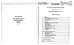
MERIDIAN 204 USER MANUAL
I
Boothroyd Stuart Ltd
13 Clifton Road
Huntingdon
Cambs. PE18 7EJ
England
Tel (0) 480 52144
Telex 32577 (MERIDN)
Fax (0) 480 459934
I
Boothroyd Stuart Ltd. Copyright 3 July 1991 (c)
Author, Rik Bean
CONTENTS
1
2
2.1
3
4
5
6
6.1
6.2
6.3
6.4
6.5
6.6
6.7
6.8
7
8
8.1
8.2
8.3
8.4
9
9.1
9.2
9.3
10
10.1
10.2
10.3
10.4
10.5
10.6
11
11.1
12
12.1
12.2
12.3
12.4
13
13.1
13.2
13.3
13.4
13.5
14
Introduction, 1
About this manual, 1
Conventions used in the manual, 1
About the 200-Series, 1
Unpacking your 204 tuner, 1
Accessories, 1
Installing your 204 Tuner, 2
General precautions, 2
Connections, 2
If you have a 201 Preamplifier, 2
207 or 208 as your preamplifier, 2
201 and a Meridian, CD Player, 2
Using D600 Loudspeakers, 2
No other Meridian equipment, 2
Antenna connection, 2
Siting, 2
Setting up the 204,3
Checking, 3
If all is well, 3
If there is a problem, 3
Standby, 3
Starting up the 204,3
Incorrect display, 3
Turning the tuner off, 3
The Display key, 3
Tuning the 204,3
Presets, 3
Search tuning, 3
Storing preset frequencies, 4
Setting the tuning threshold, 4
To vary the tuning threshold, 4
Step tuning, 4
Setting the clock, 5
To set the correct time, 5
Using the 204 as a timer, 5
Setting the timer, 5
Setting the timer condition, 5
Using a Meridian Compact Disc Player with
the timer, 5
Controlling other equipment, 5
Other features, 6
Automatic station selection on power up, 6
Changing the default display, 6
Time display in Standby mode, 6
Signal strength display, 6
Centre-tuning indicator, 6
Memory facilities, 6
15
15.1
15.2
15.3
15.4
16
16.1
16.2
17
17.1
17.2
18
19
20
20.1
20.2
21
22
23
24
25
Problems, 6
Dealing with power disturbances, 6
Dealing with memory disturbances, 6
Resetting the 201,6
Persistent problems, 7
Using the 209 Remote control, 7
Bringing the system out of standby, 7
Selecting a different preset, 7
Using 204 with D600s,7
Exiting standby, 7
Selecting a different preset, 7
Getting the best from your 204,7
Cleaning, 7
Help, 8
No sound, 8
Keys not working, 8
Maintenance & Service, 8
Radio interference, 8
Guarantee, 8
A quick operating guide, 9
Specification, 10
1 Introduction
3 About the 200-Series
The Meridian 204 Tuner is part of the 200-Series
of advanced high fidelity equipment. Used with
other components in the range, it can offer the
music lover much more than just very high quality
FM radio.
The 204 is a sophisticated device. As a result,
this manual has been divided into sections covering each group of operations. You are advised to
read through the whole manual before using your
204 for the first time, particularly if you are using it
with other 200-Series components. However, for
those of you who are familiar with high fidelity
equipment and who cannot wait to get the tuner
working, we have also provided a ‘quick guide’.
In purchasing a Meridian 204 Tuner, you have
acquired an advanced piece of equipment which
will continue to bring you listening pleasure for
many years. This manual will enable you to get
the most from it.
The Meridian 200-Series of high fidelity equipment is probably the most sophisticated family of
hi-fi products currently available. It has been developed to operate at a variety of levels, from
simple installations to a whole-house musicmanagement system. The range of components
in the 200-Series ensure that a Meridian system
will satisfy the needs of any user.
The 204 Tuner features fully-synthesised
tuning. Its circuitry has been carefully optimised to
provide the highest quality of sound available from
broadcast FM radio signals.
Despite its high performance, each piece of
equipment in the 200-Series has been designed
for ease of use, with microprocessor control being
applied throughout the range to simplify operation. We have also paid great attention to the appearance of the units, and much care has been
taken in the selection of the materials used, to
ensure that your Meridian 200-Series equipment
will look as good in years to come as it does now.
2 About this manual
This manual deals with the day-to-day operation of
the 204. Once you become familiar with it, you will
find that you do not need to refer to these instructions very often.
In any manual of this nature, some technical
terms must be used. We will explain these when
we first introduce them.
2.1 Conventions used in the manual
A number in the range 201-220 refers to a component in the Meridian 200-Series range of audio
equipment, unless otherwise indicated, for example ‘the socket marked 201’.
Whenever a key name i s printed in bold
typeface, it means that you should press this key.
When a series of key strokes are required, for example press Mode/Store then press Timer, the
key names will be separated by a hyphen, that is
Mode/Store Timer. If the key name is not in
bold type, it indicates that the course of action is
not required at present, for example ‘if you want to
change the display, press Display’ means you can
do this, but it is not essential as part of the operation currently being discussed.
Text between square brackets indicates the
appearance of the display on the front of the 204,
another 200-Series product or on the D600 digital
audio loudspeakers. For instance, [P. 231 is the
information displayed by the 204 when it is tuned
to preset 23 and the preset-number display is selected.
When we refer to a default setting, we mean
the one that will be selected if you do nothing to
change it. For example, when you first set up your
204, the default display is frequency.
-
4 Unpacking your 204 Tuner
On opening the carton, you should have found the
following parts:
Meridian 204 FM Tuner
Powercord
w Network lead (204-201) labelled ‘Q-Lead’
This manual
If any of these items are missing, please contact
your dealer immediately. We suggest that you
retain the packing as it is designed to offer the
unit maximum protection whilst in transit, AIthough d I 200-Series components have been
designed to be robust, they should obviously be
well protected when they are being transported.
.
.
5 Accessories
The following accessories are available from your
dealer:
Meridian 209 Remote control unit
Network lead (204-206) labelled ‘A-Lead’
Network lead (204-208) labelled ‘B-Lead’
Network lead (204-201) labelled ‘P-Lead’
Power cord (Europe)
Power cord (USA & Canada)
In case of difficulty, they can also be ordered
directly from the factory, the address of which can
be found on the front of this manual.
Please note that you can only use the 209
Remote control unit with your 204 Tuner if you
also have either a 201 Preamplifier or a Meridian
206, 207 or 208 Compact Disc player in your system.
...
..
204 Page 1
6 Installing your 204 Tuner
6.1 General precautions
Before carrying out any installation, you should
first ensure that the tuner is marked with the correct voltage for your local AC supply. If this is not
the case, do not proceed with these instructions,
but contact your dealer instead.
As a general rule, you should not make any
connections to the tuner, or to any other component in your system, whilst the AC power supply is connected and switched on.
6.2 Connections
You will need to connect the 204 Tuner to your
amplifier with a twin-screened audio cable or a
pair of single-screened audio cables. These can
have a considerable effect on the quality of the
sound, and we advise you to seek your dealer’s
advice on the best type for your system.
The connections you make will depend on
other components in your system.
.
.
6.3 If you have a 201 Preamplifier
Connect the sockets marked ‘Output’ on the
rear of the 204 to the Radio input on the rear of
the 201.
Connect the socket marked ‘201’ on the rear of
the tuner to the socket marked ‘200 COMMS’
on the rear of the Preamplifier using the QLead supplied with the 204.
.
.
6.4 207 or 208 as your preamplifier
Connect the sockets marked ‘Output’ on the
rear of the 204 to the input sockets marked
‘Line’ on the rear of the Compact Disc Player.
Connect the socket marked ‘CD’ on the rear of
the 204 to the socket marked ‘200 COMMS’ on
the rear of the Compact Disc Player using the
B-Lead (208) or P-Lead (207) supplied with the
Compact Disc player.
ONLY use the Q-Lead between the tuner and the
preamplifier, never between the tuner and the
Compact Disc player.
.
.
6.5 201 and a Meridian CD Player
Connect the sockets marked ‘Output’ on the
rear of the 204 to the Radio input on the rear of
the 201.
Connect the socket marked ‘201’ on the rear of
the Tuner to the socket marked ‘200 COMMS’
on the rear of the Preamplifier using the QLead supplied with the 204
Connect the socket marked ‘CD’ on the rear of
the 204 to the socket marked ‘200 COMMS’ on
the rear of the Compact Disc Player using the
A-Lead (206), B-Lead (208) or P-Lead (207)
supplied with the Compact Disc player.
ONLY use the Q-Lead between the tuner and the
preamplifier, never between the tuner and the
Compact Disc player.
.
204 Page 2
6.6 Using D600 Loudspeakers
Connect the sockets marked ‘Output’ on the
tuner to either an analogue input on the D600s,
the Radio input on the 201, or the Line input on
a 207 or 208 Compact Disc Player.
Connect the socket marked ‘CD’ on the 204 to
the M-Lead supplied with the D6OOs. Follow
the instructions in the D600 manual.
The D600s are fully-programmable and you
should consult your manual before deciding
which input to use. If you have any doubts, your
dealer will be able to help you.
6.7 No other Meridian equipment
Connect the sockets marked ‘Output’ OF the rear
of the 204 to an appropriate input on your
amplifier. You should consult the manufacturer’s
manual to determine which input to use, but
generally it will be labelled ‘Tuner’ or ‘Line’.
DO NOT, under any circumstances, connect
anything to the sockets marked ‘201/2’ or ‘CD’ on
the rear of the tuner.
6.8 Antenna connection
In all cases, a suitable VHF antenna or VHF cable
signal must be connected to the socket marked
‘RF input’ on the rear of the tuner. You are advised
to use a high-quality, low-loss co-axial cable.
Cables which have a solid screen will give superior performance.
Please note that the antenna must be intended
for unbalanced (i.e. coaxial) connection. Antennas
intended for, or connected with ribbon cable are
unsuitable. If your antenna uses a ribbon cable
then ask your dealer for a balun or consider having it reconnected. Ribbon cables are not acceptably proof against RF interference.
Please refer to the section on VHF reception
for more specific advice.
7 Siting
The 204 should not be placed on top of a power
amplifier, but it can be stacked on either the 201
Preamplifier or a Meridian Compact Disc Player.
You should avoid sites where:
it would be subjected to direct sunlight
it is near a heat source, for example a central
heating radiator
it could be subjected to strong radiation, for example very close to a television
connecting cables may be subject to interf erence
Try to keep all power cables and network leads
away from signal cables, which includes audio,
antenna and loudspeaker cables. Some time
spent carefully laying out the cables will repay you
with the best performance later.
.
.
.
.
8 Setting up the 204
9.2 Turning the tuner off
8.1 Checking
If you are using the 204 as part of a system of 200Series components or with D600s, bringing any
one of the other units out of standby will activate
all of them. Similarly, pressing Standby on one
unit will set all units into standby state if they are
connected by Network leads.
If you are not using your 204 with other
Meridian equipment, you can switch it on and off
using the power switch on the rear panel.
Before turning on the power, check once again
that you have made all the connections correctly
and that you have not disturbed any existing connections in the process.
8.2 If all is well
= turn on the power switch at the rear of the unit.
The display will illuminate briefly, [----I, and then
extinguish to leave a small point, [
1.
.
8.3 If there is a problem
Check the integrity of your power connections, including any fuses in your supply. If the display is
still not illuminated and the rest of your system is
functioning, contact your dealer for help.
8.4 Standby
The entire 200-Series is designed to be left connected to AC power at all times.
This standby state ensures that the components operate at maximum efficiency from the
moment you start listening. It is perfectly safe and
consumes a negligible amount of power
204
consumes around 5W. However, when you are
not going to use your system for an extended period, for example when you are going on holiday,
we would advise you to disconnect it from the AC
power supply.
-
9 Starting up the 204
To start up the 204, press any of the six numbered
keys, that is 1...6 . The display should now show
the frequency stored in the preset you have selected. If you have just turned the unit on for the first
time, this will be one of the factory-set defaults.
These are:
' preset 2, top of the band
preset 3,middle of the band
all others, bottom of the band
9.1 Incorrect display
If the display is incorrect, switch the unit off using
the power switch on the rear panel. Wait for a few
seconds, then turn the power on again whilst
holding down either the Start Time or Stop Time
keys on the front panel for the first 2-3 seconds.
This resets the memory of the 204 to its default
state.
Section 15 of this manual covers resetting the
204 in more detail. If you have just taken the 204
out of its box and are setting it up for the first time,
it is a good idea to switch it on in this way.
9.3 The Display key
Before we discuss tuning the 204 we should mention the Display key. When pressed, it cycles
through the three display modes of the tuner. In
order, these are frequency, time and preset number. The time and timer functions will be discussed more fully in Section 11. For now, try
pressing Display until you are familiar with its
operation. Before attempting to tune the receiver,
you should select the frequency mode.
10 Tuning the 204
The 204 Tuner uses advanced circuit technology
to achieve perfect tuning with the minimum of
user-intetvention. There are three ways of selecting the station you require, preset, search and
step tuning.
10.1 Presets
It will usually be most convenient to have commonly used stations available as preset selections. You can have up to 18 of these in three
banks. The first group, 1-6, are available directly
from the numbered keys 1-6. To access the
other two groups, you must first press the key
marked 10+ or the key marked 20+, followed by
the number you want. When you press a key, the
display will change depending on the key you
pressed. If you press a number from 1 to 6, it will
show [S. #I, where # is the number you
pressed. The 'S' stands for select. On the other
hand, if you press either 10+ or 20+, the display
shows [S. 1J or [S. 2J. In this case, the tuner
is indicating that you should enter a second digit
to select a preset in the range 11-1 6 or 21-26.
Obviously, it will make sense to have the six mostused stations in the first group of presets.
When the 204 leaves the factory, or after being
reset, all 18 presets are retuned to the factory defaults. The actual frequencies required must be
set up on site, and to do this, you will need to
employ one of the other two methods available.
10.2 Search tuning
In its default state, the 204 will employ search
tuning.
' Press the Top Green key, and the frequency
display will start to increase as the tuner looks
for a signal.
204 Page 3
e
e
As it does this, you will notice the yellow light on
the front panel, marked ‘SOKHz’, flickers. The 204
tuner steps through the VHF band in 50KHz intervals, but the display can only show lOOKHz increments. The yellow light indicates that the actual frequency is 50KHz above the indicated frequency. The allocation of VHF frequencies is such
that the yellow light will not normally be illuminated when a station is correctly tuned.
You can instruct the tuner to search in the
other direction by pressing the Bottom Green key.
When the 204 finds a station of adequate
strength, it will stop searching and display the frequency. If the station is broadcastina in stereo. the
red light or
I
also illumin
10.3 Storing preset frequencies
Once you have tuned a station you want to store
as a preset:
decide which number you wish to allocate to it
press Mode/Store-Number.
If the station is to be stored in one of the alternative banks of presets:
press Mode/Store +I0 Number, or
press Mode/Store +20 Number
In other words, to store a preset frequency, press
Mode/Store followed by the number, or shifted
number, you require and to recall it, just press the
number, or shifted number.
If the station you wish to store is very noisy, or
has a weak signal, you may prefer to listen to it in
mono. You can do this automatically by pressing
Mono before you press Mode/Store Number.
This facility applies to all 18 presets.
It is worth noting that you do not have to tune
your Dreset selections in numerical order and that
tti e tuning process will commence from the curr(wt frequency, or, in the first instance, from the
example,
bottom of the VHF band. Therefore if,-for
- - - -. .
you wanted to allocate preset 1 to 99.OMHz and
preset 2 to 88.5MHz, you would start the tuning
process as described above, and when the 204
locked onto the 88.5MHz signal, you would press
Mode/Store 2. Then you would press the Top
Green key again, and when the 99.OMHz signal
had been tuned, press Mode/Store 1 to store
the frequency in the tuner’s memory. You can also
speed up the process by tuning presets 1,2 and 3
last. This leaves them available to move to the bottom, top or middle of the band, before using the
GreenI Keys to locate your desired station.
..
..
-- --
-
-
-
10.4 Setting the tuning threshold
We mentioned above that the tuner would only
stop when it found a station of adequate strength.
This signal strength is preset at the factory, but it
can be varied to suit local conditi
204 Page 4
.
10.5 To vary the tuning threshold
-
press Mode/Store Bottom Green.
The display will now show [S.S. 11, which stands
for Stop Signal-strength 1. The strength can be
set to any figure from 0-7. A setting of 0 will allow
the weakest of signals to be tuned. This may be
helpful if you are trying to receive distant stations
or live in a poor reception area. If you only want to
receive strong signals, increase the setting until
only those signals are recognised by the 204.
To increase the threshold, and tune only strong
signals:
rn press Top Green
To decrease it and allow weaker signals to be
tuned:
press Bottom Green.
As you do this, the number displayed will change.
When the required threshold level has been selected:
rn press Mode/Store once more to store the new
threshold in memory.
You will need to experiment to find the best setting for your needs, but you can do no harm by
changing the threshold level, so feel free to explore the possibilities.
t
t
a
a
a
%:
a
.
10.6 Step tuning
The third method of tuning the 204 is to employ
step tuning. This is broadly similar to search
tuning except that you must press one of the
green keys for each 50KHz step that you wish to
make. Each time you press a green key, the frequency display will increase or decrease by
50KHz. In practice, this means that the digital display will change on every other press, alternate
presses switching the yellow light on and off.
In the step mode the tuner can scan if you hold
the green tuning key down. After pressing for a
few seconds the rate of scan will increase, scanning will stop when you release the key. Unlike
search mode, the tuner wraps at the ends of the
band in step mode from top to bottom and viceversa.
This method is less convenient than search
tuning, which is why search tuning is selected by
the tuner as its default state. To change to step
tuning:
I press Mode/Store followed by the Top Green
key
_.
..
.
...
. -_The display will now read [Srch], pressing the
Top Green key again will change this to [Step].
To complete the switch:
press Mode/Store again.
To change back to search mode tuning, repeat
the process, this time the second press of the Top
Green key will change the display from [Step] to
[Srch].
In other respects, tuning by the step method is
identical to tuning by the search method, and any
presets you wish to store can be memorised by
the same process.
.
e
12.2 Setting the timer condition
VIUUSI~,wrieri r i m
switcrieu
aispiay couia snow
ding the time. ObWII, this particular dis-
play will be meaningless.
11.1 Tosc!t the correct time
-
pressMode/Store Start Time
The Hours biutton will illuminate.
L-a ---- - A I L L
.
.
.
.
-I!press either
ureen ney ru s e r t r i e riuurs UISplay to the required figure (the 204 uses a 24
hour clock)
then press Mins and set the minutes in the
same way
To complete the operation, press Mode/Store
once more. Note that the final press of
Mode/Store starts the clock, so for maximum
accuracy, press this exactly on the minute.
I/--..A-
12 Using the 204 as a timer
Your 204 can be used to switch the entire system
on (or to a determined condition) and off at predetermined times. For this facility to work, you
must have a Meridian system consisting of a
preamplifier, and power amplifiers or active loudspeakers. The preamplifier can be a 201, or the
preamplifier facilities in a 207 or 208 Compact
Disc Player.
12.1 Setting the timeFirst, set the time at whict
turn on. To do this:
press Start Time
the Hours key will light. use me ween Keys KO
select the hour required, remembering that a
24 hour clock is used
press the Mins key, which will illuminate, and
select the required time using the Green Keys
Complete the setting operation by pressing
Start Time again
now press Stop Time
the Hours key will light. Use the Green Keys to
select the hour required, remembering that a
24 hour clock is used
press the Mins key, which will illuminate, and
select the required time using the Green Keys
ComDlete the settina oDeration bv oressina
Now put the system in the state in which you want
it to start up:
rn select the preset required
set the volume and input on the preamplifier
rn press Mode/Store Timer on the 204 to store
the timer condition in.the complete system.
rn press Timer on the 204 to arm the timer.
rn press Standby on one of the other components in the system, or use the system as
you like in the mean-time.
The system will go to the timer condition you have
specified when the start time is reached. To show
that the timer is armed, a green light will illuminate
behind the Timer key on the front panel of the
204. You can operate the system normally at any
time up to the start time. When stop time is
reached the system will go into standby.
-
12.3 Using a Meridian Compact Disc:
Player with the timer
In a system which includes a 204 Tuner and a
Meridian Compact Disc player, you can also
cause a CD to play at the start time. The procedure for this is broadly similar.
First select the start and stop times as described, then insert the chosen disc in the Compact Disc player:
rn press Play, and set the system so you can
hear the disc playing at the required volume
level
m press Mode/Store Timer on the 204 to store
the timer condition in the complete system.
= press Timer on the 204 to arm the timer.
m press Standby on the Compact Disc Player, or
use the system as you like in the mean-time.
Note that you do not have to select a tuner frequency if you are going to use Compact Disc as
your alarm source.
The system will go to the timer condition you
have specified when the start time is reached. To
show that the timer is armed, a green light will illuminate behind the Timer key on the front panel of
the 204. You can operate the system normally at
any time up to the start time. When stop time is
reached the system will go into standby.
-
12.4 Timer output
The timer function of the 204 also has an external
output. This is a 5v output that goes to Ov when
the timer function is activated and back to 5v at
the end of the timer period. Use of this output is at
the discretion of the user.
DO NOT connect anything to the socket marked
'Timer Out' on the rear panel of the 204 without
seeking advice. If you do, you may damage your
tuner.
204 Page 5
1:3 Other features
14 Memory facilities
I f1.1 Automatic station selection on
PtIwer up
As we have said, the 204 Tuner contains a battery-
It is often useful to be able to switch on the systein and have the tuner select a pre-determined
f relquency. This avoids the need to make two selec:tions, that is Radio (or Line if using a 207 or
208) followed by a preset number. To do this, selec3 the required station, then:
m press Mode/Store Number
tUlner will now automatically select this channel
wtienever it is brought out of standby, unless, of
COiurse, you override the choice by pressing a diffei'ent preset.
-
1:5.2 Changing the default display
Asi you already know, the normal display on the
2014 can show three different types of information.
WIhen you first install the tuner, the default is freq"iency.
Tc1 select a different default disolav. Dress DisDlav
I-epeatedly until the required 'infGrmation is'diiIllayed. The 204 will remember this information
Imtil you change it again.
13.3 Time display in Standby mode
... .. .
. . .. . ,. y . . tne
.. aispiay
.. .
Lvnen tne tuner is in its s m n a ~ state,
.
1. If you prefer, you
is normally a single dot, [
cain arrange to have the current time displayed,
sirmply press Display when the 204 is in standby.
Pr,essing Display repeatedly will toggle this facilitYr, and the 204 will remember the last setting ente red. Whenever the time display is selected a
gr'een light, marked 'Time Display', will illuminate
or1 the front panel of the tuner.
13.4 Signal strength display
The 204 display can also show the signal strength
of the current station to help you set the tuner. To
select this facility, press Mode/Store Display.
The display will now change to [St. #], where #
is a number from 1-7. This number will vary from
station to station and indicates the strength of the
signal from very weak (1) to very strong (7). You
can re-tune the 204 in any of the normal ways,
whilst maintaining the signal strength display.
Do not leave the signal-strength display for
normal listening, the measuring process introduces a low-level audio noise which is audible.
-
13.5 Centre-tuning indicator
-
Pressing Mode/Store Mono switches the display to a centre-tuning indicator for diagnostic
purposes. When a station is correctly tuned, the
display will show [C. 01.
Do not leave the centre-tune display for normal
listening, the measuring process introduces a
low-level audio noise which is audible.
204 Page 6
powered memory, which retains information when
the system is turned off, even if the power supply
is disconnected.
Not only does the 204 remember its own settings, but it will also remember those of a 201 Mkl
Preamplifier as long as the two units are connected by a Q-Lead. To use this facility, press
Mode Standby on the 201 after the connections
have been made to the 204. If you have a 201
Mkll, please refer to its manual for details of how
to store its own settings.
c
c
c
c
c
c
c
c
-
15 Problems
The Meridian 200-Series hi-fi components are extremely reliable under normal conditions. However, because they are controlled by microprocessors, they can occasionally be susceptible to
AC-borne disturbance and static discharges. This
is true for any similar appliance, for example video
recorders or microwave ovens.
15.1 Dealing with power disturbances
If you encounter problems with your system, for
example the keys do not work as expected or the
display becomes corrupted, try returning the system to standby for a few seconds. If the problems
persist, then switch off the AC-power for a short
while. This action will cure most problems.
15.2 Dealing with memory disturbances
It is possible for the battery-powered memory in
the 204 to have become corrupted. If this has happened, the system will remember the fault condition. To overcome such a problem:
switch off the AC-power
wait a few seconds
then turn it on again whilst pressing Start Time
or Stop Time on the front of the 204
This restores the system to the default state. You
will have to re-tune the 204, reset its clock ect.,
and reset the 201 default conditions if you have a
201 Mkl. You can avoid the need to reset the 201
by keeping it switched on whilst resetting the 204.
15.3 RI
If you have a 201 Mkl, and suspect that it is just
the 201 default conditions that have become corrupted, you can carry out a partial reset. To do
this, switch off as before, but press Mono when
restoring power. If you have a 201 Mkll, please refer to its manual.
c
L
c
c
r
c
c
c
c
c l
c
c l
-
1
D
c
c
I-
ICE
rc
e
c
(z
15.4 Persistent problems
17.1 Exiting standby
Such problems are extremely rare, and you are
unlikely to experience them. They do not indicate
any fault in the 200-Series components, and if the
above reset procedures restore normal working,
you need take no further action. In the event that
the problem persists, please contact your dealer,
service agent or the factory for further advice.
If your installation is correctly set up, bringing any
one unit out of standby will activate the entire system. The normal way to switch on the system
therefore, will be to press the required source
selector on the 609, that is Radio. If you have already selected a default preset as described
above and want to listen to it, you need do no
more.
16 Using the 209 Remote control
Please note that the 209 can only control the 204
i f t h e system also contains either a 201
Preamplifier or a Meridian Compact Disc player
and if the necessary network leads are connected.
You cannot alter the display mode, set the time, or
set the presets on the 204 remotely.
16.1 Bringing the system out of
standby
If your installation is correctly set up, bringing any
one unit out of standby will activate the entire system. The normal way to switch on the system,
therefore, will be to press the required source
selector on the 209. If you are using a 201
Preamplifier and wish to listen to the 204, then
press Radio. If you are using only a 207 or 208
Compact Disc player, then press Line. If you have
already selected a default preset as described
above and want to listen to it, you need do no
more.
16.2 Selecting a different preset
17.2 Selecting a different preset
If you want to listen to a different preset, press one
of the Number Keys on the 609. The D600 display
will change depending on the key you pressed. If
you press a number from 3 to 6, it will show
[S. #I, where # is the number you pressed. The
‘S’ stands for select. On the other hand, i f you
press either 1 or 2, the display shows [S. 1 1 or
[S. 2J. In this case, the D600 is indicating that
you can enter a second digit to select a preset in
the range 11-1 6 or 21-26.
The D600 will wait a short while, to allow you to
enter two digits, for example 1 6, before passing
the preset number to the 204.
Alternatively, press Next to select the next
highest preset or Previous to select the next
lowest. These keys will step through all 18
presets, wrapping around at each end of the
range. (i.e. Next will step from 26 to 1 and Previous from 1 to 26).
-
18 Getting the best from your 204
If you want to listen to a different preset, press
Preset on the 209, followed by the number required. The display will change depending on the
key you pressed. If you press a number from 3 to
6, it will show [S. #I, where # is the number you
pressed. The ‘S’ stands for select. On the other
hand, if you press either 1 or 2, the display shows
[S. 1J or [S. 2J. In this case, the tuner is indicating that you can enter a second digit to select a preset in the range ll-1 6 or 21-26.
The Tuner will wait a short while, to allow you
to enter two digits, for example 1 6, before
switching to the preset number entered. If you
want to select a preset in the range 1-6 and do
not want to wait, then press 0, followed by the
number you require. Once you have pressed
Preset, the system will assume all future numbers
refer to the 204 presets until you press Track.
The Meridian 204 Tuner is a very sophisticated
unit, which will deliver superb quality sound. However unless the signal delivered to the antenna
socket of the 204 is of sufficient strength and quality, you will not enjoy the maximum benefits of
your new tuner. We cannot emphasise enough
the importance of a good VHF antenna and
downlead.
However, as reception conditions vary so
much, it is impossible to give more than broad advice, and we recommend, therefore, that you consult your dealer or antenna supplier. He will be familiar with local conditions and will be able to advise you on the right equipment for your installation. Please refer to the notes in section 6.8.
In the United Kingdom, advice can also be obtained from BBC Engineering Information, Broadcasting House, London, W1A 1 M , telephone 01927 5040.
17 Using 204 with D600s
19 Cleaning
-
Please note that you cannot alter the display
mode, set the time, or set the presets on the 204
remotely.
The main body of the 204 is epoxy-enamelled
aluminium. To clean the case, use a cloth barely
moistened with a solution of mild detergent and
water. Disconnect the power cord before cleaning
the unit. Ensure that no water is allowed to get inside the case and do not reconnect the power until you are certain that the 204 is completely dry.
204 Page 7
1
The display panel is glass, the key pad is
plastic. Use a barely damp chamois leather on
these areas.
Do not use abrasive cleaners on any part of the
Tuner.
The audio sockets on the rear of the 204 are
gold-plated and need no cleaning if gold-plated
phono plugs are used. Otherwise, we recommend
that you remove and replace the plugs at least
once a year. A proprietary contact cleaner can be
20 Help
The wide range of facilities available from the
Meridian 200-Series can occasionally mean that
even the most experienced user can run into
trouble. This section is designed to help you when
things do not appear to be working normally.
20.1 Nosound
If no sound can be heard from your loudspeakers,
the most likely causes are:
No power is reaching the 204 or the entire system
The audio cable between the 204 and your
preamplifier has become disconnected
The preamplifier is not turned on; if other
Meridian 200-Series components are in the
system, they are not connected to the 204 with
the network leads supplied
The preamplifier is not set for radio input or is
in tape-monitoring mode
The volume control is set to its minimum or is
in mute condition
The threshold level on the 204 has been set
too high, preventing any stations being
received, see section 10.5.
20.2 Keys not working
If the keys on the 204 are not working correctly,
for example they produce unexpected results, the
microprocessor needs to be reset. Refer to section 15 for full details. This type of problem can
also affect other Meridian 200-Series units connected to the 204 by network leads.
21 Maintenance & Service
The Meridian 200-Series of hi-fi components have
been carefully designed to give years of untroubled service. There are no user-serviceable
parts inside the case, nor do the units require any
form of maintenance.
In the unlikely event that your 204 Tuner fails to
function correctly, and you are unable to restore
normal operation by resetting the unit as described in section 15, it should be returned, in its
original packing, to your Meridian dealer. In case
of difficulty, please write:
204 Page 8
In the UK, Boothroyd Stuart Ltd.
13 Clifton Road, Huntingdon,
Cambridgeshire, PE18 7EJ.
In the USA, Meridian America Inc.
14120-K Sullyfield Circle, Chantilly, VA 22021
Tel(703) 818 3028, Fax (703) 830 7825
Outside the UK, contact the importing agent for
the territory. A list of Meridian agents abroad is
available from the above addresses.
No responsibility can be accepted for the Tuner
whilst in transit to the factory or an agent and
customers are, therefore, advised to insure the
unit.
22 Radio interference
NOTE the 204 is a radio tuner containing a microprocessor which has been designed to very high
standards of Electromagnetic compatibility.
FCC WARNING: This equipment generates, uses
and can radiate radio-frequency energy and, if not
installed and used correctly in accordance with
our instructions, may cause interference to radio
communications or radio and television reception.
It has been type-tested and complies with the
limits set out in:
rn Subpart J, Part 15 of FCC Rules for a Class B
computing device.
These limits are intended to provide reasonable
protection against such interference in home installations.
If this equipment does cause or suffer from interference to/from radio or television reception, then
the following measures should be tried:
rn Reorient the receiving antenna or route the
antenna cable of the receiver as far as possible
from the 204 and its cabling.
= Ensure that the receiver uses well-screened
antenna cable.
Relocate the receiver with respect to the 204.
Connect the receiver and the 204 to different
AC outlets.
rn If the problem persists, contact your dealer.
..
EEC This product has been designed to comply
with EN55013 and EN55020.
REMEMBER to switch off all units before changing any connections.
23 Guarantee
The 204 Tuner is guaranteed against defects in
material and workmanship for 12 months from the
date of purchase.
The guarantee is void if the Tuner has been
subjected to misuse, accident or negligence, or
has been in any way modified without the written
authorisation of Boothroyd Stuart Ltd. Note that
connecting anything other than the correct
network leads to the sockets marked ‘201’ and
3
2
‘CD’ may cause damage to tlhe 204 which will not
be covered by this guarantele. Similarly, connecting incompatible equipment ’to the socket marked
‘Timer Out’ may cause dam: age to the 204 which
will not be covered by this gparantee. Attempted
startticinn
--.
.-.. hv
‘, I t n a t t t h n r i c m r l people may also invalidate this guarantee.
Labour and carriage charges are not covered
unless by local agreement.
When seeking service under guarantee, proof
of the date of purchase will be required.
Outside the UK, local warranty liability is
restricted to equipment purchased within the territory. Our agents abroad are only under contractual obligation to service under guarantee
equipment sold through them. They are entitled to
make a non-refundable charge for any service
carried out on other equipment.
This guarantee does not limit your statutory
rights within the United Kingdom.
- .
24 A quick operating guide
This section is a quick reminder of the operation
of the tuner and should not be seen as a substitute for the rest of the manual.
123
These keys select the six main preset
456
stations and bring the 204 out of
standby.
1o+ 20+ These are used as shift keys, before
pressing the number keys 1 to 6. When
used, t h e y a l l o w access t o t h e
secondary presets 11-1 6 and 21-26.
Green These keys are primarily used to tune
the 204, the top key increases the frequency, the bottom key decreases it.
A secondary function is to set the displayed and timer times, the type of
tuning and the tuning threshold.
Mono
Selects mono reception. Pressing it
repeatedly will toggle between stereo
and mono, in the mono state the key will
illuminate and the red light on the front
panel will extinguish.
A centre-tuning display can also be selected by pressing Mode/Store Mono.
Display If the tuner is in standby, pressing this
key will toggle between a blank display
and a time display. If the tuner is on, the
key cycles through the three possible
displays: frequency, time and preset
number.
The strength of received signals can
also be displayed by pressing
Mode/Store Display. Note that whilst
this display is selected, the Mode/Store
key will illuminate and the tuner will not
respond to pressing the Standby key on
any other component of the system, that
is you cannot turn the tuner off. To revert
to the normal display, press Mode/Store
again.
-
Mode/Store This key is always used in conjunction with others and has several functions:
To store presets. First select the required frequency using the Green Keys,
then press Mode/Store followed by a
number. For example to store the frequency in preset 1, press Mode/Store
1 and to store it in preset 12, press
Mode/Store 1O+ 2.
To change from Search to Step tuning,
or vice versa, press Mode/Store Top
Green. The display will now show the
current state. Pressing the Top Green
k e y w i l l t o g g l e t h e state, press
Mode/Store again to select the required
method.
To adjust the tuning threshold, press
Mode/Store Bottom Green. Now adjust the level using the Green Keys, then
store the value with Mode/Store.
To store the timer preset, select it using
either manual tuning or a preset, then
press Mode/Store Timer.
To identify the version number of the
tuner’s operating software, press
Mode/Store Stop Time when the
tuner is in stendby.
Start Time To set the start time, press Start Time.
A time will be displayed. The Hours key
will illuminate. Use the Green Keys to
select the correct figure, then press
Mins and adjust as required. Complete
the operation by pressing Start Time
again.
To set the displayed time is identical except that, before pressing Start Time
you must first press Mode/Store.
Stop Time To set the stop time, press Stop Time.
A time will be displayed. The Hours will
illuminate. Use the Green Keys to select
the correct figure, then press Mins and
adjust as required. Complete the operation by pressing Stop Time again.
Timer To prime the timer, press Timer and the
green light behind the key will illuminate. To cancel the alarm, press Timer
again, the green light will extinguish.
-
-
-
-
-
-
-
-
204 Page 9
25 Specification
Frequency range
Sensitivity
Ultimate quieting
Distortion
(input signal 1KHz)
Selectivity
Capture ratio
IF rejection
AM suppression
Crosstalk at 1KHz
Frequency response
Output level
Output impedance
RF input
De-emphasis
Power input
Dimensions
Weight
-
88 108MHz
30dB quieting Mono 1.5pV
50dB quieting Mono 4.0pV
Stereo 23rV
>75dB
Mono ~0.2%
Stereo ~0.4%
56dB
1.5dB
1OOdB
>55dB
40dB typ, depends on signal strength
20Hz 15KHZ *ldB
OdB 775mV
47ohm
75ohm unbalanced
50 rSec or 75 pSec
100
125V or 200
250V
50 6 0 k , 6VA
159mm x 310mm x
1OOmm ( W x L x H)
3 kg
-
-
-
-
IrC
e
ez
204 Page 70
d