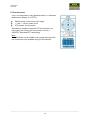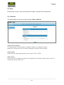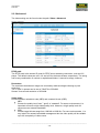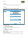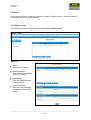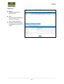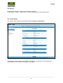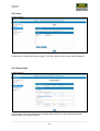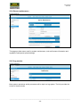
1
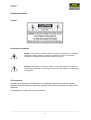
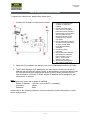
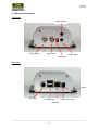
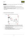
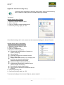
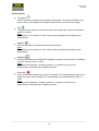
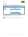
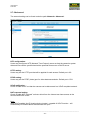
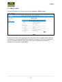
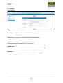
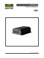
USER MANUAL
1-Channel IP Video Server
Model:
SVS-3001
Version 1.1sfi/1114/engl/A6
Dear customer,
Thank you for purchasing a high quality SANTEC device.
We recommend that you read this manual thoroughly before operating your new system for
the first time. Please follow all instructions and observe the warnings contained in this
manual.
Please contact your local dealer or SANTEC directly if you have any questions or if you wish
to claim for a service or warranty.
You will find further information on our website:
www.santec-video.com
All rights reserved. This publication may not be reproduced, stored in a retrieval system or transmitted,
in any form or by any means (electronic, mechanical, photocopying, recording or otherwise), without
the written prior permission of Sanyo Video Vertrieb AG.
No reproduction of any part or excerpts thereof are permitted.
Errors excepted. Specifications are subject to change without notice for quality improvement.
SANTEC is a registered trademark of Sanyo Video Vertrieb AG. All other companies or products
mentioned in this publication are trademarks, registered trademarks or brands of the respective
company. They are not connected in any way with Sanyo Video Vertrieb AG.
© Copyright by Sanyo Video Vertrieb AG, Ahrensburg (Germany)
User Manual
SVS-3001
Table of contents
Safety precautions
5
Safety instructions
6
About this user manual
7
Quick installation guide
8
PART I: CONNECTIONS; CABLING, TECHNICAL SPECIFICATIONS
1. General
1.1 Included items
1.2 System requirements
9
9
9
2. Connectors and ports
10
3. Connection of hardware components
11
4. Technical specifications
12
Appendix: Setup Internet security
13
PART II: CONFIGURATION AND CONTROL VIA THE WEB
1. General
14
2. Menu overview
2.1 Administration page
2.2 Live view
2.3 Video
2.3.1 General
2.3.2 Advanced
2.4 Camera
2.4.1 General
2.4.2 PTZ
2.5 Event
2.5.1 Event server
2.5.2 Motion detection
2.5.3 I/O ports
2.5.4 Event configuration
14
14
15
18
18
19
21
21
22
23
23
25
25
27
_________________________________________________________________________________
-3-
User Manual
SVS-3001
2.6. Schedule
2.6.1 General
2.6.2 Storage
2.7 Network
2.7.1 General
2.7.2 Advanced
2.7.3 SMTP (e-mail)
2.7.4 DDNS
2.8 System
2.8.1 Information
2.8.2 User
2.8.3 Date & time
2.8.4 Server maintenance
2.8.5 Log service
28
28
29
30
30
31
32
33
34
34
35
35
36
36
Appendix: Install UPnP components
37
_________________________________________________________________________________
-4-
User Manual
SVS-3001
Safety precautions
Caution
Description of symbols
Danger: This symbol is intended to alert the user to the presence of un-insulated
"dangerous voltage" within the product’s enclosure that may be of sufficient
magnitude to constitute a risk of electric shock to a person.
Warning: This symbol is intended to alert the user to the presence of important
operating and maintenance (servicing) instructions in the literature accompanying
the appliance.
CE compliance
Attention: Any changes or modifications to this appliance which have not been explicitly
approved of by the respective regulatory authority, may lead to a prohibition of usage of this
appliance.
This appliance complies with the CE guidelines.
_________________________________________________________________________________
-5-
User Manual
SVS-3001
Safety instructions
Before operating the appliance, please read this manual carefully and retain it for further
reference.
Before cleaning the appliance, it has to be switched off and unplugged from the power outlet.
Wipe the appliance with a soft damp cloth.
Do not use harsh cleansers or aerosols for cleaning. The type label may not be replaced.
Do not use attachments unless recommended by the manufacturer as they may affect the
functionality of the appliance and result in the risk of fire, electric shock or injury.
Never install the appliance in areas exposed to water or other liquids.
The appliance has to be installed in a safe and stable location according to the instructions of the
manufacturer. Care should be used when moving heavy equipment. Quick stops, excessive force,
and uneven surfaces may cause the appliance to fall causing serious injury to persons and
damage to objects.
Openings in the appliance, if any, are provided for ventilation to ensure reliable operation of the
appliance and to protect if from overheating. These openings must not be covered or blocked.
Please make sure that the appliance does not overheat.
The appliance should only be operated from the type of power source indicated on the marking
label. If you are not sure of the type of power supplied at the installation location, please contact
your local dealer.
An appliance which is powered through a polarized plug (a plug with one blade wider than the
other) will fit into the power outlet only one way. This is a safety feature. If you are unable to insert
the plug into the outlet, try reversing the plug. Do not defeat the safety purpose of the polarized
plug.
If the appliance is powered through a grounding-type plug, the plug will only fit into a groundingtype power outlet. This is a safety feature. If your outlet does not have the grounding plug
receptacle, contact your local electrician.
Route power cords and cables in a manner to protect them from damage by being walked on or
pinched by items places upon or against them.
For protection of the appliance during a lightning storm or when it is left unattended and unused
for a longer period, unplug the appliance from the wall outlet. Disconnect any antennas or cable
systems that may be connected to the appliance. This will prevent damage to the appliance due to
lightning or power-line surges.
Do not overload wall outlets and extension cords as this can result in a risk of fire or electric
shock.
Never insert items into the openings of the appliance. They may touch parts under electric current
which may cause an electric shock.
Never pour any liquids over the appliance.
_________________________________________________________________________________
-6-
User Manual
SVS-3001
In case of any operating interruption or a complete operating failure please switch off the
appliance and disconnect it from the wall outlet. Never attempt to service or repair the appliance
yourself, as opening or removing covers may expose you to dangerous voltage or other hazards.
Refer all servicing to qualified service personnel.
When replacement parts are required, be sure that the service technician uses replacements parts
specified by the manufacturer or that have the same characteristics as the original part.
Unauthorized substitutions may result in fire, electric shock or other hazards.
Upon completion of any service or repairs to the appliance, ask the service technician to perform
safety checks to verify that the appliance is in proper operating condition.
The appliance should only be installed by qualified service personnel and has to comply with local
specifications and regulations.
Never point the camera at an object with a high degree of luminance. Bright vertical or horizontal
lines can result in a distortion (outshine) of the entire image on the monitor. This artifact is not an
error but a particularity of semiconductor CCDs when they are directly exposed to a powerful light
source.
If the camera is operated in locations with extremely differing light conditions, the aperture has to
be adapted.
Please respect the local legal regulations on waste if you need to dispose of discarded appliances.
This symbol means that electrical appliances need to be disposed of properly and not
simply with unsorted household refuse. Please respect local regulations on waste
disposal.
About this user manual
This manual aims at assisting the user on how to operate the video server SVS-3001.
This manual is subject to rigid quality control. However, no guarantee can be given that mistakes are
not present. We reserve the right to make changes to the manual without prior notice.
Before operating the appliance, please read this manual carefully and retain it for further reference.
Verify that all appliance items are included in the delivery. Should items be missing, do not operate the
appliance and contact your local dealer.
Never attempt to repair the appliance yourself. This should only be done by qualified service
personnel.
Improper handling of the appliance will invalidate the warranty.
Subject to technical changes without prior notice. Errors excepted.
_________________________________________________________________________________
-7-
User Manual
SVS-3001
QUICK INSTALLATION GUIDE
To operate the video server, please follow these steps:
1. Connect the hardware components as follows:
1. Prepare a PC/laptop with
an Ethernet link to the
network.
2. Connect the SVS-3001
video server to a network
hub/switch with a standard
pass through (CAT5) cable.
You may also connect
SVS-3001 directly to the
PC/laptop using a cross
over cable.
3. Connect the video output of
the camera using standard
75 Ohm coaxial cable
terminated with BNC
connector.
4. Connect to power
(12V DC).
5. Ensure the power adapter
specifications match the
power system (110 V or
220 V). Connect the
adapter to the outlet.
6. Check both LEDs (power
and network); both lights
should be on.
2. Insert the CD (included in the delivery) into your PC/laptop and install the IP-finder.
3. The IP-finder displays an IP address for the video server. Double-click on the IP
address and the Internet Explorer comes up automatically. In case this doesn’t work,
you may also enter the IP address (as shown by the IP-finder) manually into the
Internet Explorer. Using the IP-finder, another IP address can be assigned to the
video server, if required.
Note:
The video server comes with a default IP address:
Default IP address: 192.168.1.168 (or DHCP, if available)
User name:
admin
Password:
9999
Please refer to the following chapters in this user manual for further information on video
server configurations.
_________________________________________________________________________________
-8-
User Manual
SVS-3001
Part I: Connection, installation, technical specifications
1. General
The SANTEC 1-channel IP video server SVS-3001 can encode and transmit video signals
from analogue cameras into an IP signal with MJPEG or H.264 compression.
1.1 Items included in the delivery
1x
1x
1x
1x
1x
Video server SVS-3001
CD (IP finder and user manual)
Quick installation guide
Power adapter
Breakout cable
1.2 System requirements
To control the video server via the web browser, please ensure your PC has a good network
connection and meets the system requirements as described below.
Item
Personal Computer
Operating System
Web browser
Network Card
Viewer
System requirement
1. Intel® Pentium® M, 2.16 GHz or
Intel® CoreTM2 Duo, 2.0 GHz
2. 2 GB RAM or more
Windows VISTA / Windows XP / Windows 7
Microsoft Internet Explorer 6.0 or higher
10Base-T (10 Mbps) or 100Base-TX (100 Mbps)
ActiveX control plug-in for Microsoft Internet Explorer
_________________________________________________________________________________
-9-
User Manual
SVS-3001
2. Connectors and ports
Front view:
Audio output
Video output
Video input
Audio input
Terminator
Rear view:
Reset
Com/GPIO
2x USB ports
Power (12 V DC)
LAN port
_________________________________________________________________________________
- 10 -
User Manual
SVS-3001
Reset button:
The reset button is used to restore the factory default settings. To do so, please follow
these steps:
1. Unplug the power jack to turn off the video server.
2. Insert a pin into the reset hole and press and hold the reset button for approx. 10
seconds.
3. Plug-in the power jack to turn on the video server while keep pressing the reset button.
The power LED will start flashing after a short while.
4. Release the pin when the LED starts quick flashing. The video server is now restored to
factory default.
3. Connection of hardware components
1.
Prepare a PC/laptop with an Ethernet link to the network.
2.
Connect the SVS-3001 video server to a network hub/switch with a standard
pass through (CAT5) cable. You may also connect SVS-3001 directly to the
PC/laptop using a cross over cable.
Connect the video output of the camera using standard 75 Ohm coaxial cable
terminated with BNC connector.
Connect the power jack (12 V DC).
Ensure the power adapter specifications match the power system (110 V or
220 V). Connect the adapter to the outlet.
Check both LEDs (power and network); both lights should be on.
3.
4.
5.
6.
_________________________________________________________________________________
- 11 -
User Manual
SVS-3001
4. Technical specifications
Device
Type
SVS-3001
1-channel video server
Video input/output
1x BNC / 1x BNC
Compression (video)
Number of video streams
Resolution
Max. frame rate
Deinterlacing
Motion detection
Audio inputs/outputs
Digital inputs/outputs
RS-485 interface
PTZ control
Design
Number of Ethernet ports
Ethernet standards
Ethernet connector
Ethernet speed
Power-over-Ethernet (PoE)
USB interface
SD card slot
Video Content Analytics (VCA)
Voltage
Operating temperature
Relative humidity
Dimensions (W x H x D)
Weight
Certification
MJPEG / H.264
3
D1, 2CIF, CIF, QCIF
25 fps at D1 (720x576)
Yes, DSP
Yes
1 / 1 (3.5 mm phone jack)
No / No
Yes
Yes
Desktop
1
10Base-T/100Base-TX
RJ-45
10/100 Mbit
No
2x USB 2.0
No
Yes
12 V DC
0° to +50° C
20 to 80% non-condensing
121 x 119 x 46 mm
450 g
CE
Subject to technical changes without notice. Errors excepted.
_________________________________________________________________________________
- 12 -
User Manual
SVS-3001
Appendix: Internet security setup
If ActiveX control installation is blocked, please either set the Internet security
level to default or change ActiveX controls and plug-in settings.
Internet security level: Default:
1.
2.
3.
4.
Open the „Internet Options“ menu.
Select “Security”.
Click on „Reset all zones to default level“.
Confirm by clicking “Apply” or “OK”.
If the default settings don’t work, please use the customized settings for ActiveX Controls.
Internet security level: Customized:
Open the „Internet Options“ menu.
Select “Security”.
Click on „Custom level“
Enable the following options:
All previously unused ActiveX Controls run
without prompting.
Allow scriptlets.
Automatic promptinf for ActiveX Controls.
Binary and scripts.
Display video and animation on a webpage that
does not use external media player
Download signed ActiveX controls
Download unsigned ActiveX Controls.
Initialize and script ActiveX controls are not
marked as safe for scripting
Run ActiveX Controls and plug-ins.
Script ActiveX Controls are marked as safe for
scripting. .
5. Confirm by clicking “OK“.
6. Confirm by clicking „Apply“ or „OK“.
1.
2.
3.
4.
To activate all settings in the Internet Explorer, please restart it!
_________________________________________________________________________________
- 13 -
User Manual
SVS-3001
Part II: Control via the web
1. General
The SVS-3001 video server is equipped with a user-friendly browser-based configuration
interface. In this part of the user manual, information on system related settings and control
options will be described in detail.
Start your web browser and enter the URL or the IP address in the address field:
Default IP address:
Default username
Default password:
:
192.168.1.168
(or DHCP-assigned address, if available
(see IP-Finder))
admin
9999
If a security window pops up, please click on „install“.
The live view of the camera is displayed now.
2. Menu overview
Once the video server is connected to the power and the device is accessed via the web
browser, you will see the following main tabs on the top of the screen:
<Live view>, <Video>, <Camera>, <Event>, <Schedule>, <Network> and <System>.
2.1 Administration page
Click on the <Admin> button in the live view (see screenshot) to access the administration
page.
Here you can make a number of adjustments and settings (see the following chapters).
_________________________________________________________________________________
- 14 -
User Manual
SVS-3001
2.2 Live view
Admin button
(go to administration page)
Language
setting
PTZ control
panel
Action buttons
(Full screen, talk, speaker,
snapshot, recording)
Channel selection
Supported languages:
On the live view page, you can select your language by clicking on the respective flag icon:
English or German.
Admin button:
To exit the <Live view> and to make changes to the camera set-up, click on the <Admin>
button.
_________________________________________________________________________________
- 15 -
User Manual
SVS-3001
Action buttons:
Full screen
Click this button to display the live image as full screen. To exit the full screen view
and to return to the regular view, please double-click into the full screen image.
Talk
The talk function allows the local site to talk to the remote site. Click on the button to
switch it to on/off.
Note:
This function is only open to a “user” who has been granted this privilege by the
administrator.
Speaker
Click on this button to mute/activate the audio function.
Note:
This function is only open to a “user” who has been granted this privilege by the
administrator.
Snapshot
Click on this button and a JPEG/JPG snapshot is made of the live picture. By default,
it will be stored on your C:\ drive.
Note:
For users with Windows 7 operating system, it is required to log on as an
administrator to implement the snapshot function.
Recording
Click on this button and the live picture is recorded. The recording button lights up in
bright red colour while recording. The recorded clip is by default saved to your C:\
drive.
Note:
For users with Windows 7 operating system, it is required to log on as an
administrator to implement the snapshot function.
_________________________________________________________________________________
- 16 -
User Manual
SVS-3001
PTZ control panel:
The PTZ control panel is only displayed when PTZ has been
enabled (see chapter “2.4.2 PTZ”).
Pan/tilt arrows: Click to move the image.
“+” and “-“: Click to zoom in/out.
PTZ presets: List of presets.
Alternatively, instead of using the PTZ control panel, you
may simply click into the live view picture to move it
(SANTEC “EasyViewPTZ” technology).
Note:
The OSD button (in the middle of the control panel) and the
tour function are only available using a Pelco protocol.
_________________________________________________________________________________
- 17 -
User Manual
SVS-3001
2.3 Video
Under the tab <Video>, there are submenus including: <General> and <Advanced>.
2.3.1 General
The video setting can be found under the path: Video > General
Video general setting:
The video stream can be enabled or disabled. Stream1 is enabled by default.
Maximum 3 streams can be concurrently enabled for different client requests.
Video signal:
Select the video signal appropriate for your region: PAL or NTSC.
OSD setting:
Check this item to enable information to be displayed in the image: Camera name (max. 20
characters) and/or date & time.
_________________________________________________________________________________
- 18 -
User Manual
SVS-3001
2.3.2 Advanced
The video setting can be found under the path: Video > Advanced
RTSP path:
The RTSP path is the stream ID used for RTSP client streaming connection, such as VLC
player. The default values are v00, v01 and v02 for the three streams respectively. The string
can be any combination of number or capital/small letters. It cannot be empty, however.
Resolution:
The resolution describes an image size counted by width and height referring to pixel
resolution.
The 1st and 2nd stream can be set to 720x576 or 352x288.
Stream 3 has a fixed resolution of 352x288.
Video mode:
Choose between variable bit rate (VBR) and constant bit rate (CBR):
VBR:
Choose the quality level “best”, “good” or “standard”. For some environments, it is
important to ensure a high video quality level. However, a high quality level will
consume more network bandwidth.
CBR:
Choose target bit rate range from 1000 Kb to 6000 Kb. For some environments, it is
very helpful for network bandwidth management but the video quality will be variable
up to the complexity of video scene.
_________________________________________________________________________________
- 19 -
User Manual
SVS-3001
Image format:
H.264 and MJPEG are available for image format selection. The term “image format” is
referring to compression/encoding technique. The selected image format influences the
performance of bandwidth and storage requirement. With regards to video quality, H.264
contributes to less bandwidth and storage requirement, which is more efficient than MJPEG.
GOP:
GOP (group of pictures) describes how the different types of frames are arranged. The frame
types implemented here are I-frame (full image information) and P-frame (motioncompensated difference information). This setting configures the GOP length which is the
number of frames before the next I-frame appears. The lower the number of frames, the
higher the video quality you will get. On the other hand, it will consumer more network
bandwidth and storage size.
Frame rates:
The frame rates define the number of frames that will be displayed per second. The frame
rate setting can affect the target bit rate (bandwidth requirement) and storage requirement.
_________________________________________________________________________________
- 20 -
User Manual
SVS-3001
2.4 Camera
Under the tab <Video>, there are submenus including: <General> and <PTZ>.
2.4.1 General
The camera setting can be found under the path: Camera > General
Camera general setting:
Brightness: Luminance of image.
Hue: Color hue can be modified.
Saturation: Intensity of a specific color.
Contrast: Difference in color and light between parts of an image.
Audio setting:
Audio enable: Turn on/off the audio.
Encoder: Select “G711” or “AAC”.
Web record setting:
Save path / File name: Click on “Browse” to select the desired path to save the video file.
Web snapshot image setting:
Save path / File name: Click on “Browse” to select the desired path to save the video file.
_________________________________________________________________________________
- 21 -
User Manual
SVS-3001
2.4.2 PTZ
The camera setting can be found under the path: Camera > PTZ
PTZ status:
Select “enable” or “disable. The PTZ control panel in live view is only displayed if the PTZ
status is set to “enable”.
PTZ protocol:
The following protocols are supported: Pelco D, Pelco P, Li-Lin, Li-Lin New, Dynacolor.
Device ID:
Set the ID for the video server (1-63).
Speed (only applicable if speed domes are used):
Adjust the speed of the speed dome (1-10).
Port mode:
Select RS-485, RS-232 or PTZ.
Baud rate:
Transmission speed to/from PTZ device.
Data bit:
Data transfer rate.
Stop bit:
A start signal is sent prior to each byte, character or code word and a stop signal is sent after
each code word.
Parity:
Parity of an object states whether it is even or odd.
_________________________________________________________________________________
- 22 -
User Manual
SVS-3001
2.5 Event
Under the tab <Event>, there are submenus including: <Event server>, <Motion detection>,
<I/O ports> and <Event configuration>.
2.5.1 Event server
The event setting can be found under the path: Event > Event server
Add FTP:
Name:
Name the FTP server.
Network address:
Enter the network address
of the FTP server.
Upload path:
Enter the desired upload
path for events.
Login information:
Enter the user name and
the password for the FTP
server.
_________________________________________________________________________________
- 23 -
User Manual
SVS-3001
Add HTTP:
Name:
Enter the name of the
HTTP server.
URL:
Enter the network address
of the HTTP server.
User name / password:
Enter the user name and
the password for the HTTP
server.
_________________________________________________________________________________
- 24 -
User Manual
SVS-3001
2.5.2 Motion detection
The motion detection setting can be found under the path: Event > Motion detection.
To create a motion detection area, follow these steps:
1. Click on “Add” to set-up a detection area.
2. Give a name to this window area.
3. Select the trigger level and the sensitivity level for this detection window (0-100).
4. Select a color for the detection window by clicking on the color palette.
5. Click in the picture and drag the mouse to create a motion detection window.
6. Click on “Save” to store the configurations.
The thus configured detection window will be displayed in the motion detection list.
Note:
The maximum number of detection windows is 10.
The motion detection window needs to be modified if users change the video layout.
_________________________________________________________________________________
- 25 -
User Manual
SVS-3001
2.5.3 I/O ports
The I/O port setting can be found under the path: Event > I/O ports.
This video server supports 2 photo-coupled relay inputs and 1 relay output.
_________________________________________________________________________________
- 26 -
User Manual
SVS-3001
2.5.4 Event configuration
The event configuration setting can be found under the path: Event > Event configuration.
To add an event trigger, follow these steps:
1. Click on “Add” and the setup panel will be expanded (as shown above).
2. Give a name to this event.
3. Set the time interval between the triggers.
4. Set the time period for the trigger. Choose “Always” or “During time between” or
“Never”.
5. Triggered by: Select “motion detection” from the drop-down menu.
6. Choose the corresponding action once a motion has been detected.
7. Click on “Save” to store the configurations.
_________________________________________________________________________________
- 27 -
User Manual
SVS-3001
2.6 Schedule
Under the tab <Schedule>, there are submenus including: <General> and <Storage>.
2.6.1 General
The schedule setting can be found under the path: Schedule > General.
Follow the steps below on how to set a schedule:
1. Check the “Enabled” box.
2. Select the video stream to be recorded.
3. Define the size of each sliced file (MB).
4. Define the day of the week and the time (by hour of the day) of the scheduled period
to be recorded (simply click into the respective field).
5. Click on “Save” to activate the schedule.
Note:
Recording files are saved to a USB storage device. Hence it is necessary that a USB storage
device is connected to the USB port of the video server in order for the schedule to be
displayed.
_________________________________________________________________________________
- 28 -
User Manual
SVS-3001
2.6.2 Storage
The schedule setting can be found under the path: Schedule > Storage.
Here, information on the storage status is displayed. A message is displayed when a
recording is currently running.
Note:
The USB storage device must not be removed from the USB port during the recording
process.
_________________________________________________________________________________
- 29 -
User Manual
SVS-3001
2.7 Network
Under the tab <Network>, there are submenus including:
<General>, <Advanced>, <SMTP (e-mail)> and <DDNS>.
2.7.1 General
The network setting can be found under the path: Network > General.
On this page, the IP configuration is displayed including DHCP and static IP setting.
“Enable ARP/ping” enables the camera to accept ARP or ping packets from the network.
Disabling this option may provide extra security from intentional ping.
The default IP address is 192.168.1.168 if no DHCP service is available.
_________________________________________________________________________________
- 30 -
User Manual
SVS-3001
2.7.2 Advanced
The network setting can be found under the path: Network > Advanced.
NTP configuration:
Users may configure a NTP (Network Time Protocol) server so that the camera’s system
date and time can be synchronized with a specified time server or DHCP server.
HTTP setting:
Users may set the HTTP port that will be applied for web access. Default port = 80.
RTSP setting:
Users may set the RTSP (video) port for video data transmission. Default port = 554.
UPnP notification:
Check “Enable UPnP” so that the camera can be discovered in a UPnP compliant network.
NAT traversal setting:
Check “Enable NAT traversal” so that a client from the Internet can have access to the
devices behind the router.
Note:
With UPnP enabled, the IP sharing device (router) – capable of UPnP function – will
automatically be notified about the camera’s NAT port.
_________________________________________________________________________________
- 31 -
User Manual
SVS-3001
2.7.3 SMTP (e-mail)
The network setting can be found under the path: Network > SNTP (e-mail).
Configure an e-mail host for the camera which will send e-mails on behalf of the configured
e-mail account to a specified mail address (also see the chapter “2.5.4 Event configuration”).
Fill-in the information about the mail server, server port, authentication information (if
required) and the sender’s e-mail address.
_________________________________________________________________________________
- 32 -
User Manual
SVS-3001
2.7.4 DDNS
Check the box “DDNS enable” for dynamic DNS configuration.
Host name:
Assigned name that will be used for accessing the video server.
User name / password:
Account authentication for logging on to this service.
Update time:
Periodically, the camera updates its access information in the defined time.
Response:
The video server responds to the connection information (yes or no).
_________________________________________________________________________________
- 33 -
User Manual
SVS-3001
2.8 System
Under the tab <System>, there are submenus including:
<Information>, <User>, <Date & time>, <Server maintenance> and <Log service>.
2.8.1 Information
The system setting can be found under the path: System > Information.
On this page, a list of system and network configuration is displayed. These data are for
information only and cannot be changed on this page.
_________________________________________________________________________________
- 34 -
User Manual
SVS-3001
2.8.2 User
Check the box “Enable anonymous login” if you don’t wish to have a user name displayed.
2.8.3 Date & time
On this page, users may configure the system date and time as well as synchronization
options with a PC and NTP server.
_________________________________________________________________________________
- 35 -
User Manual
SVS-3001
2.8.4 Server maintenance
This page provides some tools for system maintenance, such as firmware information and
upgrades, backup and upload settings.
2.8.5 Log service
Most system operations and/or processes will be kept in a log system. The link provides the
review of these records.
_________________________________________________________________________________
- 36 -
User Manual
SVS-3001
Appendix: Install UPnP components
For Windows XP:
Please proceed as follows to install UPnP for Windows XP:
1. Go to <Start>, then click on klicken dann auf <Control Panel> and double-click on
<Add or Remove Programs>.
2. Click on <Software>.
3. Click on <Add/Remove Windows Components>.
4. In the Windows wizard window, click on <Networking Services>> and then on
<Details>.
5. Select <UPnP user interface> and confirm with <OK>.
6. Click on <Next>.
7. Click on <Finish> to complete the installation.
For Windows Vista and Windows 7:
Please proceed as follows to install UPnP for Windows Vista and Windows 7:
By default, the windows firewall blocks network discovery (formally called UPnP technology),
but you can enable it in the following way:
1. Click on <Start> and then click on <Control Panel>.
2. Click on <Network and Internet> and then on <Network and sharing center>.
3. If the network discovery (UPnP) is off, click on the arrow icon
section.
to expand the
4. Click on <Turn on network discovery> and then on <Apply>. If prompted for an
administration password or a confirmation, please type the password or provide the
confirmation.
_________________________________________________________________________________
- 37 -
User Manual
SVS-3001
Notes:
_________________________________________________________________________________
- 38 -
User Manual
SVS-3001
Notes:
_________________________________________________________________________________
- 39 -
Your local distributor:
__________________________________________________________________________
www.santec-video.com