1
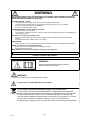
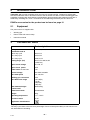
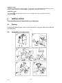
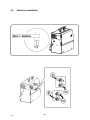
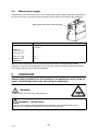
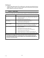
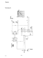
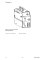
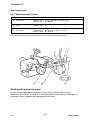
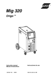
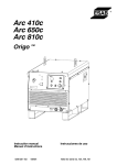
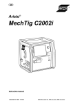
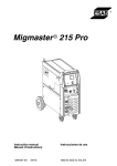
Tradesmig 141
Instruction manual
0349 301 142
080424
Valid for serial no. 811
DECLARATION OF CONFORMITY
Murex Welding Products Ltd.
Declare hereby that:
Murex Tradesmig 141
Part No. 0349 309 291
Manufactured after 1st May 2005
S
conform with the requirements of Council Directive 72/23/EEC, amended by
Council Directive 93/68/EEC, relating to electrical equipment designed for use
within certain voltage limits.
S
conform with the requirements of Council Directive 89/336/EEC, amended by
Council Directive 93/68/EEC, relating to electromagnetic compatibility.
S
are manufactured in accordance with EN60974-1 Safety Requirements for Arc
Welding Equipment.
S
are manufactured in accordance with EN60974-10 Electromagnetic Compatibility
for Arc Welding Equipment.
On behalf of oMurex Welding Products Ltd.
Hanover House, Queensgate
Britannia Road, Waltham Cross
Herts. EN8 7TF
England
Kent Eimbrodt
Global Director
Equipment and Automation
Manufactured by Esab Welding Equipment AB.
-- 2 -declaration
ENGLISH
1 SAFETY . . . . . . . . . . . . . . . . . . . . . . . . . . . . . . . . . . . . . . . . . . . . . . . . . . . . . . . . . . .
2 INTRODUCTION . . . . . . . . . . . . . . . . . . . . . . . . . . . . . . . . . . . . . . . . . . . . . . . . . . .
4
6
2.1 Equipment . . . . . . . . . . . . . . . . . . . . . . . . . . . . . . . . . . . . . . . . . . . . . . . . . . . . . . . . . . . . . . . .
6
3 TECHNICAL DATA . . . . . . . . . . . . . . . . . . . . . . . . . . . . . . . . . . . . . . . . . . . . . . . . .
4 INSTALLATION . . . . . . . . . . . . . . . . . . . . . . . . . . . . . . . . . . . . . . . . . . . . . . . . . . . .
6
7
4.1
4.2
4.3
4.4
Placing . . . . . . . . . . . . . . . . . . . . . . . . . . . . . . . . . . . . . . . . . . . . . . . . . . . . . . . . . . . . . . . . . . .
Assembly of components . . . . . . . . . . . . . . . . . . . . . . . . . . . . . . . . . . . . . . . . . . . . . . . . . . .
Electrical installation . . . . . . . . . . . . . . . . . . . . . . . . . . . . . . . . . . . . . . . . . . . . . . . . . . . . . . .
Mains power supply . . . . . . . . . . . . . . . . . . . . . . . . . . . . . . . . . . . . . . . . . . . . . . . . . . . . . . . .
7
7
8
9
5 OPERATION . . . . . . . . . . . . . . . . . . . . . . . . . . . . . . . . . . . . . . . . . . . . . . . . . . . . . . .
9
5.1 Connection and control devices . . . . . . . . . . . . . . . . . . . . . . . . . . . . . . . . . . . . . . . . . . . . .
5.2 Functions explanation . . . . . . . . . . . . . . . . . . . . . . . . . . . . . . . . . . . . . . . . . . . . . . . . . . . . . .
10
10
6 MAINTENANCE . . . . . . . . . . . . . . . . . . . . . . . . . . . . . . . . . . . . . . . . . . . . . . . . . . . .
10
6.1 Inspection and cleaning . . . . . . . . . . . . . . . . . . . . . . . . . . . . . . . . . . . . . . . . . . . . . . . . . . . .
10
7 FAULT TRACING . . . . . . . . . . . . . . . . . . . . . . . . . . . . . . . . . . . . . . . . . . . . . . . . . . .
DIAGRAM . . . . . . . . . . . . . . . . . . . . . . . . . . . . . . . . . . . . . . . . . . . . . . . . . . . . . . . . . . . .
WEAR COMPONENTS . . . . . . . . . . . . . . . . . . . . . . . . . . . . . . . . . . . . . . . . . . . . . . . . .
ACCESSORIES . . . . . . . . . . . . . . . . . . . . . . . . . . . . . . . . . . . . . . . . . . . . . . . . . . . . . . .
11
12
14
15
Rights reserved to alter specifications without notice.
TOCe
-- 3 --
1
SAFETY
Users of welding equipment have the ultimate responsibility for ensuring that anyone who works on
or near the equipment observes all the relevant safety precautions. Safety precautions must meet
the requirements that apply to this type of welding equipment. The following recommendations
should be observed in addition to the standard regulations that apply to the workplace.
All work must be carried out by trained personnel well--acquainted with the operation of the welding
equipment. Incorrect operation of the equipment may lead to hazardous situations which can result
in injury to the operator and damage to the equipment.
1.
Anyone who uses the welding equipment must be familiar with:
S its operation
S location of emergency stops
S its function
S relevant safety precautions
S welding
2.
The operator must ensure that:
S no unauthorised person is stationed within the working area of the equipment when it is
started up.
S no--one is unprotected when the arc is struck
3.
The workplace must:
S be suitable for the purpose
S be free from draughts
4.
Personal safety equipment
S Always wear recommended personal safety equipment, such as safety glasses, flame--proof
clothing, safety gloves.
S Do not wear loose--fitting items, such as scarves, bracelets, rings, etc., which could become
trapped or cause burns.
5.
General precautions
S Make sure the return cable is connected securely.
S Work on high voltage equipment may only be carried out by a qualified electrician.
S Appropriate fire extinquishing equipment must be clearly marked and close at hand.
S Lubrication and maintenance must not be carried out on the equipment during operation.
-- 4 -T141e
WARNING
ARC WELDING AND CUTTING CAN BE INJURIOUS TO YOURSELF AND OTHERS. TAKE PRECAUTIONS WHEN WELDING. ASK FOR YOUR EMPLOYER’S SAFETY PRACTICES WHICH SHOULD BE
BASED ON MANUFACTURERS’ HAZARD DATA.
ELECTRIC SHOCK -- Can kill
S
Install and earth the welding unit in accordance with applicable standards.
S
Do not touch live electrical parts or electrodes with bare skin, wet gloves or wet clothing.
S
Insulate yourself from earth and the workpiece.
S
Ensure your working stance is safe.
FUMES AND GASES -- Can be dangerous to health
S
Keep your head out of the fumes.
S
Use ventilation, extraction at the arc, or both, to take fumes and gases away from your breathing zone
and the general area.
ARC RAYS -- Can injure eyes and burn skin.
S
Protect your eyes and body. Use the correct welding screen and filter lens and wear protective
clothing.
S
Protect bystanders with suitable screens or curtains.
FIRE HAZARD
S
Sparks (spatter) can cause fire. Make sure therefore that there are no inflammable materials nearby.
NOISE -- Excessive noise can damage hearing
S
Protect your ears. Use earmuffs or other hearing protection.
S
Warn bystanders of the risk.
MALFUNCTION -- Call for expert assistance in the event of malfunction.
READ AND UNDERSTAND THE INSTRUCTION MANUAL BEFORE INSTALLING OR OPERATING.
PROTECT YOURSELF AND OTHERS!
WARNING!
Read and understand the instruction manual
before installing or operating.
WARNING!
Do not use the power source for thawing frozen pipes.
This product is solely intended for arc welding.
Do not dispose of electrical equipment together with normal waste!
In observance of European Directive 2002/96/EC on Waste Electrical and Electronic
Equipment and its implementation in accordance with national law, electrical equipment
that has reached the end of its life must be collected separately and returned to an
environmentally compatible recycling facility. As the owner of the equipment, you should
get information on approved collection systems from our local representative.
By applying this European Directive you will improve the environment and human health!
-- 5 -T141e
2
INTRODUCTION
Tradesmig 141 are step controlled power sources in a compact design, intended for welding with
solid steel, stainless steel or aluminium wire as well as tubular wire with or without shielding gas.The
possibility of welding with homogeneous wire/shielding gas and welding with gasless tubular wire is
obtained by switching the + and -- connections on the switching terminal by the wire feed unit.
ESAB’s accessories for the product can be found on page 15.
2.1
Equipment
The power source is supplied with:
S
Welding gun
S
Return cable with return clamp
S
Instruction manual
3
TECHNICAL DATA
Tradesmig 141
Voltage
230--240V, 1∼ 50/60Hz
Permissible load at
100% duty cycle
42A/16,1V
60 % duty cycle
54A/16,7V
20 % duty cycle
100A/17,0V
Setting range (DC)
35A/15,7V--83A/18,2V
(130A/13,4)
Open circuit voltage
18,7--25,1V
Open circuit power
75W
Power factor at max load
0,91
Control voltage
230--240V, 50/60Hz
Wire feed speed
2,0--14m/min
Welding gun connection
fixed
Wire dimension range
0,6--0,8(Fe)
1,0 (Al)
0,8(cored)
0,8(CuSi)
Max diameter/weight
of wire bobin
200mm/5kg
Dimensions lxwxh
650x300x550
Weight
25kg
Operating temperature
--10 ÷ +40oC
Enclosure class
IP 23
Application classification
Duty cycle
The duty cycle refers to the time as a percentage of a ten--minute period that you can weld at a certain load without overloading.
-- 6 -T141e
Enclosure class
The IP code indicates the enclosure class, i. e. the degree of protection against penetration by solid
objects or water. Equipment marked IP23 is designed for indoor and outdoor use.
Application class
The symbol
indicates that the power source is designed for use in areas with increased
electrical hazard.
4
INSTALLATION
The installation must be executed by a professional.
4.1
Placing
Position the welding power source such way that its cooling air inlets and outlets are
not obstructed.
4.2
Assembly of components
-- 7 -T141e
4.3
Electrical installation
-- 8 -T141e
4.4
Mains power supply
Check that the unit is connected to the correct mains power supply voltage, and that it is protected by
the correct fuse size. A protective earth connection must be made, in accordance with regulations.
Rating plate with supply connection data
Tradesmig 141
Voltage V
230--240V,
1∼ 50/60Hz
Current A
at 100% duty cycle
5,1
at 60% duty cycle
7,0
at 20% duty cycle
13,8
Cable area
mm2
Fuse slow A
3 x 1.5
10
NB: The mains cable areas and fuse sizes as shown above are in accordance with Swedish
regulations. They may not be applicable in other countries: make sure that the cable area and fuse
sizes comply with the relevant national regulations.
5
OPERATION
General safety regulations for the handling of the equipment can be found on
page 4. Read through before you start using the equipment!
WARNING!
Rotating parts can cause injury, take great care.
WARNING - TIPPING RISK!
There is a risk of tipping while transportation and operation, if the welding machine leans
more than 10o. In that case appropriate securing has to be provided !
-- 9 -T141e
5.1
Connection and control devices
1
Welding voltage switch
OFF + 4 steps (mains ON/OFF)
4
Return cable with clamp, fixed
2
Orange indicating lamp, overheating
5
Knob for wire speed setting
3
Welding gun, fixed
5.2
Functions explanation
5.2.1
Overheating protection
If the internal temperature becomes too high, the welding is interrupted and disabled.
This state is indicated by lighting of the orange indicating lamp [2] on the front of the machine. It resets automatically when the temperature has fallen.
6
MAINTENANCE
Regular maintenance is important for safe, reliable operation.
Note!
All guarantee undertakings from the supplier cease to apply if the customer himself
attempts any work in the product during the guarantee period in order to rectify any
faults.
6.1
Inspection and cleaning
Check regularly that the power source is free from dirt.
The power source should be regularly blown clean using dry compressed air at reduced
pressure. More frequently in dirty environments. Otherwise the air inlet/outlet may become blocked and cause overheating.
-- 10 -T141e
Welding gun
Cleaning and replacement of the welding gun’s wear parts should take place at
regular intervals in order to achieve trouble--free wire feed. Blow the wire guide
clean regularly and clean the contact tip.
S
7
FAULT TRACING
Try these recommended checks and inspections before sending for an authorised service technican.
Actions
Type of fault
No arc
S
Check that the mains power supply switch is turned on.
S
Check that the welding current supply and return cables are
correctly connected.
S
Check that correct current value is set.
S
Check whether the thermal overload trip has operated
(indicated by the orange lamp on the front).
S
Check the main power supply fuses.
Thermal overload trips
operate frequently
S
Check to see whether the air inlets/outlets are clogged.
S
Make sure that you are not exceeding the rated data for the
power source (i.e. that the unit is not being overloaded).
Poor welding performance
S
Check that the welding current supply and return cables are
correctly connected.
S
Check that the correct current value is set.
S
Check that the correct welding wires are being used.
S
Check the main power supply fuses.
S
Check the wire feed unit -- if proper rolls are applied and
properly set the pressure of the wire feeder’s pressure rollers
Welding current is interrupted
during welding
Tradesmig 141 is designed and tested in accordance with the international and European standards IEC/EN 60974--1 and EN 60974--10. It is the obligation of the service
unit which has carried out the service or repair work to make sure that the product still
conforms to the said standard.
-- 11 -T141e
Diagram
Tradesmig 141
-- 12 -dT141
Tradesmig 141
Valid for serial no. 811--XXX--XXXX
Ordering numbers
0349 311 670
Tradesmig 141
230--240V 1∼
∼50/60Hz
-- 13 -oT141
Edition 080424
Tradesmig 141
Wear components
(W. F. Mechanism 0469 475 880)
Denomination
Ordering no.
Notes
A
Feed roller
0469 517 001
0349 311 443
Ø 0.6--0.8mm Fe, cored wire, CuSi
Ø 1.0mm Al
B
Liner
0700 200 099
0349 311 441
Fe, cored wire, CuSi
Al
C
Contact tip
0700 200 063
0700 200 064
0349 311 442
Ø 0.6mm Fe
Ø 0.8mm Fe, cored wire, CuSi
Ø 1.0mm Al
Item
The rollers are marked with wire dimension in mm, some are also marked with inch.
Welding with aluminium wires.
In order to weld with aluminium wires, proper rollers, nozzles and liners for
aluminium wires MUST be used. It is recommended to use 3m long welding gun for
aluminium wires, equipped with appropriate wear parts.
-- 14 -wT141
Edition 080424
Tradesmig 141
Accessories
Traction KIT . . . . . . . . . . . . . . . . . . . . . . . . . . . .
-- 15 -aT141
0349 309 073
Edition 080424