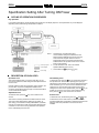
1
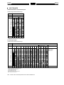
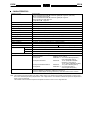
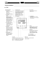
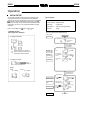
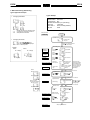
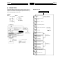
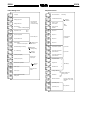
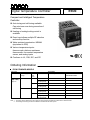
Digital Temperature Controller
E5CN
Compact and Intelligent Temperature
Controller
Auto-tuning and self-tuning available.
Can auto-tune even during execution of
self-tuning
Heating or heating/cooling control is
available
Event input allows multiple SP selection
and run/stop function
Water-resistant construction: NEMA4
(equivalent to IP66)
Various temperature inputs:
thermocouple, platinum resistance
thermometer, non-contact temperature
sensor, and analog inputs
Conforms to UL, CSA, IEC, and CE
Ordering Information
E5CN STANDARD MODELS
Description
Size
Part number
Power supply
voltage
1/16 DIN
100 to 240 VAC
48(W) x 48(H) x
78(D) mm
No. of
alarm
points
Output
Thermocouple model
Platinum resistance
thermometer model
---
Relay
E5CN-RMTC-500 AC100-240
E5CN-RMP-500 AC100-240
Voltage output
(for driving SSR)
E5CN-QMTC-500 AC100-240
E5CN-QMP-500 AC100-240
Relay
E5CN-R2MTC-500 AC100-240
E5CN-R2MP-500 AC100-240
Voltage output
(for driving SSR)
E5CN-Q2MTC-500 AC100-240
E5CN-Q2MP-500 AC100-240
Relay
E5CN-RMTC-500 AC/DC24
E5CN-RMP-500 AC/DC24
Voltage output
(for driving SSR)
E5CN-QMTC-500 AC/DC24
E5CN-QMP-500 AC/DC24
Relay
E5CN-R2MTC-500 AC/DC24
E5CN-R2MP-500 AC/DC24
Voltage output
(for driving SSR)
E5CN-Q2MTC-500 AC/DC24
E5CN-Q2MP-500 AC/DC24
2
24 VAC/VDC
---
2
Note: 1. The suffix “500” is added to the part number of each Controller provided with a E53-COV10 Terminal Cover.
2. The heating and cooling function is available for models with two alarm points.
E5CN
E5CN
E5CN OPTION BOARDS
The E5CN provides communications or event input functionality when mounted with one of the following Option Boards.
Item
Function
Part number
Communications Board
RS-485 communication
E53-CNH03
Event Input Board
Event input
E53-CNHB
Note: The heater burnout alarm is available by mounting the E53-CNH03 or E53-CNHB Option Unit on the E5CN.
ACCESSORIES
Terminal Cover (Sold Separately)
Applicable Controller
Part number
E5CN
E53-COV10
Current Transformer (Sold Separately)
Item
Hole diameter
Part number
Current Transformer
5.8 dia.
E54-CT1
12.0 dia.
E54-CT3
E5CN
E5CN
INPUT RANGES
Platinum Resistance Thermometer Input
Shaded ranges indicate default settings.
Platinum resistance thermometer input
Input type
Platinum resistance thermometer
Temperature range
Name
1800
1700
1600
1500
1400
1300
1200
1100
1000
900
800
700
600
500
400
300
200
100
0
--100
--200
Set value
Pt100
JPt100
850
500.0
--200
--199.9
0
1
500.0
100.0
100.0
0.0
0.0
--199.9
2
3
4
Thermocouple Input
Shaded ranges indicate default settings.
Thermocouple input
Input type
K
Temperature range
Name
1800
1700
1600
1500
1400
1300
1200
1100
1000
900
800
700
600
500
400
300
200
100
0
--100
--200
Set value
ES1A Non-contact
Temperature Sensor
Thermocouple
J
T
E
L
U
N
R
S
B
K10 to
70°C
K60 to
120°C
Analog input
K115 to K160 to
165°C 260°C
0 to 50 mV
1800
1700
Usable in the following
ranges by scaling:
--19999 to 9999 or
--199.9 to 999.9
1700
1300
1300
850
850
600
500.0
400.0
400
400
260
120
165
0
0
0
0
12
13
14
15
70
100
0
--20.0
--20.0
--100
--200
0
--200
1
2
0
0
9
10
--100
3
4
--200
5
6
7
--200
8
Applicable standards by input type are as follows:
K, J, T, E, N, R, S, B: JIS C1602-1995
L: Fe-CuNi, DIN 43710-1985
U: Cu-CuNi, DIN 43710-1985
JPt100: JIS C1604-1989, JIS C1606-1989
Pt100: JIS C1604-1997, IEC751
Note: The ES1A Non-contact Temperature Sensor will be available soon.
11
16
E5CN
E5CN
Specifications
RATINGS
Supply voltage
100 to 240 VAC, 50/60 Hz
Operating voltage range
85% to 110% of rated supply voltage
Power consumption
7 VA
E5CN
Sensor input
Control output
24 VAC, 50/60 Hz/24 VDC
4 VA/3 W
Thermocouple: K, J, T, E, L, U, N, R, S, B
Platinum resistance thermometer: Pt100, JPt100
Non-contact temperature sensor: K10 to 70C, K60 to 120C, K115 to 165C, K160 to 260C
Voltage input: 0 to 50 mV
Relay output
SPST-NO, 250 VAC, 3A (resistive load), electrical life: 100,000 operations
Voltage output
12 VDC (PNP), max. load current: 21 mA, with short-circuit protection
Alarm output
SPST-NO, 250 VAC, 1 A (resistive load), electrical life: 100,000 operations
Control method
PID or ON/OFF control
Setting method
Digital setting using front panel keys
Indication method
7-segment digital display and single-lighting indicator
Other functions
According to Controller model
Ambient temperature
-10C to 55C (14F to 131F) with no condensation or icing
Ambient humidity
25% to 85% relative humidity
Storage temperature
-25C to 65C (-13F to 149F) with no condensation or icing
E5CN
E5CN
CHARACTERISTICS
Indication accuracy
Thermocouple:
( 0.5% of indicated value or 1C, whichever greater)
Platinum resistance thermometer:
( 0.5% of indicated value or 1C, whichever greater)
Analog input: 0.5% FS 1 digit max.
CT input: 5% FS 1 digit max.
1 digit max. (See Note.)
1 digit max.
Hysteresis
0.1 to 999.9 EU (in units of 0.1 EU)
Proportional band (P)
0.1 to 999.9 EU (in units of 0.1 EU)
Integral time (I)
0 to 3999 s (in units of 1 s)
Derivative time (D)
0 to 3999 s (in units of 1 s)
Control period
1 to 99 s (in units of 1 s)
Manual reset value
0.0% to 100.0% (in units of 0.1%)
Alarm setting range
-1999 to 9999 (decimal point position depends on input type)
Sampling period
500 ms
Insulation resistance
20 MΩ min. (at 500 VDC)
Dielectric strength
2000 VAC, 50 or 60 Hz for 1min (between different charging terminals)
Vibration resistance
10 to 55 Hz, 10 m/s2 for 2 hours each in X, Y and Z directions
Shock resistance
300 m/s2, 3 times each in 3 axes, 6 directions (relay: 100 m/s2)
Weight
Protective structure
Approx. 150 g
Mounting bracket: Approx. 10g
Front panel
NEMA4 for indoor use (equivalent to IP66)
Rear case
IP20
Terminals
IP00
Memory protection
EEPROM (non-volatile memory) (number of writes: 100,000)
EMC
Emission Enclosure:
Emission AC Mains:
Immunity ESD:
Immunity RF-interference:
Immunity Conducted Disturbance:
Immunity Burst:
Approval standards
EN55011 Group 1 class A
EN55011 Group 1 class A
EN61000-4-2: 4 kV contact discharge (level 2)
8 kV air discharge (level 3)
ENV50140:
10 V/m (amplitude modulated,
80 MHz to 1 GHz) (level 3)
10 V/m (pulse modulated, 900 MHz)
ENV50141:
10 V (0.15 to 80 MHz) (level 3)
EN61000-4-4: 2 kV power-line (level 3)
2 kV I/O signal-line (level 4)
UL3121-1, CSA22.2 No. 14, E.B.1402C
Conforms to EN50081-2, EN50082-2, EN61010-1 (IEC1010-1)
Conforms to VDE0106/part 100 (Finger Protection), when the terminal cover is mounted.
Note: The indication of K thermocouples in the -200 to 1300°C range, and T and N thermocouples at a temperature of -100°C or less,
and U and L thermocouples at any temperature is ±2°C±1 digit maximum. The indication of B thermocouples at a temperature of
400°C or less is unrestricted.
The indication of R and S thermocouples at a temperature of 200°C or less is ±3°C±1 digit maximum.
E5CN
E5CN
COMMUNICATIONS SPECIFICATIONS
Transmission path connection
Multiple points
Communications method
RS-485 (two-wire, half duplex)
Synchronization method
Start-stop synchronization
Baud rate
1,200/2,400/4,800/9,600/19,200 bps
Transmission code
ASCII
Data bit length
7 or 8 bits
Stop bit length
1 or 2 bits
Error detection
Vertical parity (none, even, odd)
Frame check sequence (FCS): with SYSMAC WAY
Block check character (BCC): with CompoWay/F
Flow control
Not available
Interface
RS-485
Retry function
Not available
Communications buffer
40 bytes
Note: The baud rate, data bit length, stop bit length, or vertical parity can be individually set using the communications setting level.
CURRENT TRANSFORMER (SOLD SEPARATELY) RATINGS
Dielectric strength
1,000 VAC (1 min)
Vibration resistance
50 Hz 98 m/s2
Weight
g
Accessories (E54-CT3
(
only)
y)
E54-CT1
Approx. 11.5 g
E54-CT3
Approx. 50 g
Armature
2
Plug
2
HEATER BURNOUT ALARM SPECIFICATIONS
Max. heater current
Single-phase AC: 50 A (See Note 1.)
Input current readout accuracy
±5%FS±1 digit max.
Heater burnout alarm setting range
0.0 to 50.0 A (0.1 A units) (See Note 2.)
Min. detection ON time
190 ms (See Note 3.)
Note: 1. When heater burnout is detected on a 3-phase heater, use the K2CU-F
A- GS (with gate input terminal).
2. When the set value is “00 A,” the heater burnout alarm will always be OFF. When the set value is “50.0 A,” the heater burnout
alarm will always be ON.
3. When the control output ON time is less than 190 ms, heater burnout detection and heater current measurement will not be
carried out.
E5CN
E5CN
Nomenclature
E5CN
Operation Indicators
1. AL1 (alarm 1)
Lights when alarm 1 output is ON.
AL2 (alarm 2)
Lights when alarm 2 output is ON.
2. HB (heater burnout alarm
display)
Lights when a heater
burnout is detected.
The heater burnout alarm
remains ON by setting the
heater burnout latch. To
reset, turn the power supply OFF and then ON or
set the heater burnout
alarm value to “0.0A.”
3. OT1, OT2 (control output
1, control output 2)
Lights when control output
1 and/or control output 2
(cool) are ON.
4. STP (stop)
Lights when control of the
E5CN has been stopped.
During control, this indicator lights when an event or
the run/stop function has
stopped, or this indicator
is out.
5. CMW (communications
writing control)
Lights when communications writing is enabled
and is out when it is
disabled.
Temperature Unit
No. 1 Display
The temperature unit is displayed
when the display unit parameter
is set to a temperature. Indication
is determined by the currently
selected “temperature unit”
parameter set value. When this
parameter is set to “°C,” “” is
displayed, and when set to “°F,”
“” is displayed.
Displays the process value or
parameter type.
No. 2 Display
Displays the set point, manipulated variable, or set value (setup)
of the parameter.
Up Key
Each press of this key increases
values displayed on the No.2
display. Holding down this key
continuously increases values.
Down Key
Each press of this key decreases
values displayed on the No.2
display. Holding down this key
continuously decreases values.
Level + Mode Keys
This key combination sets the
E5CN to the “protect level.”
Level Key
Mode Key
Press this key to select the setup level. The
setup level is selected in this order: “operation
level” ←→ “adjustment level,” “initial setting
level” ←→ “communications setting level.”
Press this key to select parameters
within each level.
E5CN
E5CN
Operation
INITIAL SETUP
On previous Controllers, sensor input type, alarm type and
control period were set on DIP switches. These hardware
settings are now set in parameters in setup menus. The
and
keys are used to switch between setup menus, and the
amount of time that you hold the keys down determines which
setup menu you move to. This section describes two typical
examples.
Note: On the E5GN, the
Key is the
1. ON/OFF Control
Typical Application Examples
Key.
Typical Example
Input type:
0 K thermocouple -200 to 1300°C
Control method: ON/OFF control
Alarm type:
2 upper limit
Alarm value 1:
20°C (For setting deviation)
Set point:
100°C
Change only the alarm value 1 and set point.
The rest must be left as default settings.
Setup procedure
•
Changing Parameters
Power ON
Power ON
Operation level
Process value/
set point
Press
key for at least
three seconds.
Control stops.
Initial setting level
indicates that there is a parameter.
Keep on pressing the mode key until
the desired parameter is selected.
•
Changing Set Values
Set input
specifications
Check input
type.
Input type
Set control
specifications
Check that control is ON/OFF
control.
In ON/OFF
control Set alarm type
Check alarm
type.
Alarm 1
type Use the
or
keys to
change the set value displayed
in the setup menu.
Display
E5CN
No. 1 display
E5GN
No. 1 display
Press
key for at
least one second.
Operation level
No. 2 display
No. 2 display
Set the set point
Check operation
state
Press
keys
to set set point to
“100C.”
Make sure that
control is running.
Process value/
set point During run
During stop
Set alarm values
Start operation
Press
keys
to set alarm value
to “20C.”
Start operation
Alarm
value 1
E5CN
E5CN
2. PID Control Using Auto-tuning
Typical Application Example
•
Typical Example
Changing Parameters
Input type:
4 T thermocouple -200 to 400°C
Control method: PID control
ST (self-tuning): OFF
Calculate PID constants by AT (auto-tuning).
Alarm type:
2 upper limit
Alarm value 1:
30°C (For setting deviation)
Set point:
150°C
indicates that there is a parameter. Keep
on pressing the mode key until the desired parameter is selected.
Setup procedure
Power ON
Power ON
Operation level
•
Process value/
set point
Changing Set Values
Use the
or
keys to
change the set value displayed
in the setup menu.
Press
key for at least three
seconds. Control stops.
Initial setting level
Display
E5CN
No. 1 display
E5GN
No. 1 display
Set input
specifications
Press
keys to select
input type.
Input type Press
keys to select
PID control.
In PID control
Set control
specifications
Press
keys to set ST
to OFF.
To cancel ST
No. 2 display
No. 2 display
Self-tuning
Check control period
Check the
control period.
Control period
(heat) (unit:
seconds)
Check alarm type
Check alarm
type.
Alarm 1 type (upper-limit
alarm)
PV/SP
Press
After AT execution.
When set to ON,
self-tuning operates.
Recommended settings: 20 seconds for
the relay output and
2 seconds for the
SSR output.
key for at least one second.
Operation level
Set the set point
During AT execution.
Press
keys
to set set point to
“150C.”
Process value/
set point Press
key for less than one second.
Adjustment level
While AT is being
executed, SP will flash.
After AT execution.
AT execution
Execute AT
(auto-tuning).
To execute AT
Press
key for less than one second.
Operation level
During AT execution.
Set operation status
Set alarm values
Start operation
Make sure that
set point is
“150C.”
Process value/
set point Make sure that
control is running.
During run
Press
keys to set
alarm value to
“30C.”
Set to for executing AT and to for stopping AT.
Alarm
value 1
Start program execution
E5CN
E5CN
Specification Setting After Turning ON Power
OUTLINE OF OPERATION PROCEDURES
Key Operation
In the following descriptions, all the parameters are introduced in the display sequence. Some parameters may not be displayed
depending on the protect settings and operation conditions.
Power ON
Operation level
Adjustment level
+
key
1 second min.
key
Less than
1 second
key
3 second min.
key
1 second min.
Control stops
Protect level
Communications
setting level
Initial setting level
key
Less than
1 second
key
1 second min.
Password input
set value “--169”
Advanced
function setting level
Password input
set value “1201”
Calibration level
Note: 1. Of these levels, the initial setting level,
communications setting level, advanced function
setting level and calibration level can be used only
when control has stopped. Note that control is
stopped when these four levels are selected. When
switched back to the operation level from one of these
levels, control will start.
Control in progress
2. For the calibration mode, refer to the relevant
Operation Manual (H100 or H101).
Control stopped
3. On the E5GN, the
Key is the
Key.
Level change
DESCRIPTION OF EACH LEVEL
Operation Level
Initial Setting Level
This level is displayed when you turn the power ON. You can
move to the protect level, initial setting level and adjustment level
from this level.
To select this level, press the
key for at least three seconds in
the operation level. This level is for specifying the input type,
selecting the control method, control period, setting direct/reverse
action and alarm type. You can move to the advanced function
setting level or communications setting level from this initial
setting level. To return to the operation level, press the
key for
at least one second. To move to the communications setting
key once for less than one second.
level, press the
Normally, select this level during operation. During operation, the
process value, set point and manipulated variable can be
monitored, and the alarm value and upper- and lower-limit alarms
can be monitored and modified.
Adjustment Level
To select this level, press the
second.
key once for less than one
This level is for entering set values and offset values for control.
This level contains parameters for setting the set values, AT
(auto-tuning), communications writing enable/disable, hysteresis,
multi-SP, input shift values, heater burnout alarm (HBA) and PID
constants. You can move to the top parameter of the operation
level or initial setting level from here.
Protect Level
To select this level, simultaneously press the
and
keys
for at least one second. This level is to prevent unwanted or
accidental modification of parameters. Protected levels will not be
displayed, and so the parameters in that level cannot be
modified.
E5CN
E5CN
Communications Setting Level
Calibration Level
To select this level, press the
key once for less than one
second in the initial setting level. When the communications
function is used, set the communications conditions in this level.
Communicating with a personal computer (host computer) allows
set points to be read and written, and manipulated variables to be
monitored.
To select this level, you must enter the password (“1201”) in the
advanced function setting level. This level is for offsetting
deviation in the input circuit.
Advanced Function Setting Level
To select this level, you must enter the password (“-169”) in the
initial setting level.
You can move only to the calibration level from this level.
This level is for setting the automatic return of display mode, MV
limiter, event input assignment, standby sequence, alarm
hysteresis, ST (self-tune) and to move to the user calibration
level.
You cannot move to other levels by operating the keys on the
front panel from the calibration level. To cancel this level, turn the
power OFF then back ON again.
E5CN
E5CN
SPECIFICATION SETTING (AFTER
TURNING ON POWER)
Initial Setting Level
This level is used for setting basic specifications of the
Temperature Controller. Using this level, set the input type for
selecting the input to be connected such as the thermocouple or
platinum resistance thermometer and set the range of set point
and the alarm mode.
Initial setting level
Input type
Scaling upper limit
Power ON
Scaling lower limit
Adjustment level
key
Less than 1 second
Operation level
key
1 second min.
key
3 second min.
+
key
1 second min.
Decimal point
Control stops.
Temperature unit
Protect level
Initial setting
level
Communications
setting level
key
Less than 1 second
key
1 second min.
Set point upper limit
Password input
set value “-169”
Set point lower limit
Advanced function
setting level
Password input
set value “1201”
PID / ON/OFF
Calibration level
: ON/OFF control
: PID control
Standard/heating and
cooling
: Standard
: Heating/cooling
The move from the operation level to the initial setting level,
key for three seconds or more.
press
ST
: Enabled
: Disabled
The initial setting level is not displayed when
“initial/communications protection” is set to “2.” This initial setting
level can be used when “initial setting/communications
protection” is set to “0” or “1.”
Control period (heat)
Control period (cool)
The “scaling upper limit,” “scaling lower limit,” and “decimal point”
parameters are displayed when an analog voltage input is
selected as the input type.
Direct/reverse operation
: Reverse
operation
: Direct
operation
Alarm 1 type
Alarm 2 type
Move to advanced
function setting level
To return to the operation level, press the
one second
*Not
key for longer than
displayed as default setting.
Note: 1. Displayed only with models provided with an alarm
function.
2. Displayed only with the E5CN provided with a twopoint alarm function.
E5CN
E5CN
INPUT TYPE
Using a Thermocouple Input Type
When using a thermocouple input type, follow the specifications listed in the following table.
Input type
Specifications
Set Value
Input Temperature Range
Thermocouple
K
0
--200 to 1300 (°C)
1
--20.0 to 500.0 (°C) /0.0 to 900.0 (°F)
2
--100 to 850 (°C)
3
--20.0 to 400.0 (°C) /0.0 to 750.0 (°F)
T
4
--200 to 400 (°C)
/--300 to 700 (°F)
E
5
0 to 600 (°C)
/0 to 1100 (°F)
L
6
--100 to 850 (°C)
/--100 to 1500 (°F)
U
7
--200 to 400 (°C)
/--300 to 700 (°F)
N
8
--200 to 1300 (°C)
/--300 to 2300 (°F)
R
9
0 to 1700 (°C)
/0 to 3000 (°F)
S
10
0 to 1700 (°C)
/0 to 3000 (°F)
B
11
100 to 1800 (°C)
/300 to 3200 (°F)
K10 to 70C
12
0 to 90 (°C)
/0 to 190 (°F)
K60 to 120C
13
0 to 120 (°C)
/0 to 240 (°F)
K115 to 165C
14
0 to 165 (°C)
/0 to 320 (°F)
K160 to 260C
15
0 to 260 (°C)
/0 to 500 (°F)
0 to 50mV
16
One of following ranges depending on the
results of scaling: 1999 to 9999, 199.9 to
999.9
J
Non-contact temperature sensor ES1A
Analog input
/--300 to 2300 (°F)
/--100 to 1500 (°F)
Note: The initial settings are: 0: --200 to 1300C/--300 to 2300F.
Using a Platinum Resistance Thermometer Input Type
When using the platinum resistance thermometer input type, follow the specifications listed in the following table.
Input type
Specifications
Set Value
Input Temperature Range
Platinum resistance thermometer
Pt100
0
--200 to 850 (°C)
JPt100
Note: 1. The initial settings are: 0: Pt100 --200 to 850C/--300 to 1500F.
2. The ES1A Non-contact Temperature Sensor will be available soon.
/--300 to 1500 (°F)
1
--199.9 to 500.0 (°C)/--199.9 to 900.0 (°F)
2
0.0 to 100.0 (°C)
3
--199.9 to 500.0 (°C)/--199.9 to 900.0 (°F)
4
0.0 to 100.0 (°C)
/0.0 to 210.0 (°F)
/0.0 to 210.0 (°F)
E5CN
E5CN
ALARM 1 AND ALARM 2
For the alarm 1 and alarm 2, select alarm types out of the 12 alarm types listed in the following table.
Alarm Output Operation
Set Value
Alarm Type
y
0
Alarm function OFF
1*1
Upper- and lower-limit (deviation)
When X is positive
When X is negative
Output OFF
*2
2
Upper-limit (deviation)
3
Lower-limit (deviation)
4*1
Upper- and lower-limit range
(deviation)
*3
Upper- and lower-limit with standby
sequence (deviation)
*4
5*1
6
Upper-limit with standby sequence
(deviation)
7
Lower-limit with standby sequence
(deviation)
8
Absolute-value upper-limit
9
Absolute-value lower-limit
10
Absolute-value upper-limit with
standby sequence
11
Absolute-value lower-limit with
standby sequence
*1: With set values 1, 4 and 5, the upper and lower limit values
can be set independently for each alarm type and are expressed
as “L” and “H.”
Following operations are for cases when an alarm set point is “X”
or negative.
*2: Set value: 1, upper- and lower-limit alarm
Case 1
Case 2
*4: Set value: 5, upper- and lower-limit with standby sequence
Case 1
Case 2
Example
Same as for the upper- and lower-limit
alarm. However, when the upper limit
and lower limit hysteresis overlaps:
Always OFF
Case 3 (Always ON)
Example: When the alarm is set ON at 110C/F or higher.
• When an alarm type
• When the absoluteother than the absolutevalue alarm is selected
value alarm is selected
(For alarm types 8 to 11)
*3: Set value: 4, upper- and lower-limit range
Case 1
Case 2
Case 3 (Always OFF)
(For alarm types 1 to 7)
The alarm value is set as a
deviation from the set point.
The alarm value is set as an
absolute value from the alarm
value of 0C/F.
Alarm value
Set point
100°C/°F
Alarm value
0°C/°F
E5CN
E5CN
PARAMETERS
Parameters related to setting items for each level are marked in
boxes in the flowcharts and brief descriptions are given as
required. At the end of each setting item, press the mode key to
return to the beginning of each level.
Operation Level
Power ON
Display
E5CN
No. 1 display
E5GN
PV
No. 1 display
Add in the “additional
PV display” parameter.
PV/SP
No. 2 display
No. 2 display
Multi-SP
Power ON
Set point during SP ramp
Operation level
key
1 second
min.
Select SP.
Heater current value monitor
Adjustment level
key
Less than 1 second
+
key
1 second min.
key 3 second min.
Run/stop
Control stops.
Protect level
Initial setting level
Communications
setting level
Password input
set value “1201”
Calibration level
: RUN
: STOP
Alarm value 1
key
Less than 1 second
Upper-limit
alarm value 1
key
Password input
1 second
set value “-169”
min.
Advanced function
setting level
Current value
monitor of HBA
Set either of
these parameters.
Lower-limit
alarm value 1
Control in progress
Control stopped
Alarm value 2
Level change
Upper-limit
alarm value 2
Lower-limit
alarm value 2
MV monitor (heat)
MV monitor (cool)
Set either of
these parameters.
E5CN
E5CN
Initial Setting Level
Adjustment Level
Input type
AT execute/cancel
Auto-tuning
Communications writing
Scaling upper limit
For analog input
(Input type: 16)
0- to 50-mV setting
Scaling lower limit
Heater current
value monitor
Decimal point
Number of displayed digits
Heater burnout
detection
Temperature unit
Set point 0
: °C
: °F
: Enabled
: Disabled
HBA
function
Set point 1
Set point upper limit
Limit the set point.
Set point lower limit
PID / ON/OFF
Select the control system.
Standard/heating and cooling
ST
Self-tuning
Set points used
by multi-SP
Set point 2
: ON/OFF control
: PID control
: Standard
: Heating/cooling
: Enabled
: Disabled
Set point 3
Temperature input shift
1-point shift
Upper-limit temperature
input shift value
2-point shift
Lower-limit temperature
input shift value
Control period (heat)
Set the pulse
output cycle.
Control period (cool)
Direct/reverse operation
Proportional band
: Reverse
: Direct
Alarm 2 type
Integral time
Select the alarm
mode.
PID settings
I
Derivative time
Alarm 1 type
P
D
Cooling coefficient
Used in heating and
cooling control
Move to advanced function
setting level
Dead band
Manual reset value
Clear the offset during
stabilization of P or PD
control.
Hysteresis (heat)
Set hysteresis.
Hysteresis (cool)
E5CN
E5CN
Advanced Function Setting Level
Protect Level
Operation/adjustment protection
Parameter initialize
Resets to the default value.
Restricts display and modification of menus in the
operation and adjustment levels.
Initial setting/communications protection
Restricts display and modification of menus in the initial
setting, operation level and adjustment levels.
Number of multi-SP uses
Setting change protection
Protects changes to setups by operating the front
panel keys.
Event input assignment 1
Input setting: Multiple
SP/RUN/STOP
Event input assignment 2
Operation/Adjustment Protection
The following table shows the relationship between set values
and the range of protection.
Multi-SP uses
Set value
Level
0
SP ramp set value
Operation
l
level
l
Other
Adjustment level
Alarm 1 open in alarm
ON/OFF setting of alarm
output 1
2
3
X
X
X
X
PV/SP
Standby sequence reset
method
Alarm 1 hysteresis
1
PV
X
When this parameter is set to “0,” parameters are not protected.
Default setting: 0
Alarm 2 open in alarm
ON/OFF setting of alarm
output 2
: Can be displayed and changed
: Can be displayed
: Cannot be displayed and move to other levels not possible
Alarm 2 hysteresis
Initial Setting/Communications Protection
This protect level restricts movement to the initial setting level,
communications setting level and advanced function setting level.
HBA ON/OFF
Initial setting
level
Communications
setting level
1
2
X
X
Heater burnout latch
Set
value
Heater burnout hysteresis
0
ST stable range
Advanced
function
setting level
X
X
For setting deviation.
Default setting: 1
α
PID parameter
: Move to other levels not possible
MV upper limit
Limitations to MV
MV lower limit
Input digital filter
For setting time constant in seconds.
Additional PV display
: Move to other levels possible
Setting Change Protection
This protect level protects setup from being changed by
operating the keys on the front panel.
Set value
Description
OFF
Setup can be changed by key operation.
ON
Setup cannot be changed by key operation.
(The protect level, can be changed.)
Displayed first in the operation level
Manipulated variable display
Automatic return of display mode
Automatically reset to the operation level
when no key operation are performed.
Move to calibration level
Default setting: OFF
E5CN
E5CN
Communications Setting Level
Set the E5CN/E5GN communications specifications in the communications setting level. For setting communications parameters, use the
E5CN/E5GN panel. The communications parameters and their settings are listed in the following table.
Parameter
Displayed characters
Set (monitor) value
Set value
Communications unit No.
0 to 99
0.1 to 99
Baud rate
1.2/2.4/4.8/9.6/19.2 (kbps)
1.2/2.4/4.8/9.6/19.2
Data bits
7/8 (bit)
7/8 (bit)
Stop bits
1/2
1/2 (bit)
Parity
None, even, odd
//
Note: The highlighted values indicate default settings.
Before executing communications with the E5CN/E5GN, set the
communications unit No., baud rate, etc., through key operations
as described below. As for other operations, refer to the relevant
Operation Manual.
1. Press the
key for at least three seconds in the “operation
level.” The level moves to the “initial setting level.”
key for less than one second. The “initial
2. Press the
setting level” moves to the “communications setting level.”
3. Pressing the
key advances the parameters as shown
in the following figure.
4. Press the
or
keys to change the parameter setups.
Communications
unit No.
Communications Unit No. ()
When communicating with the host computer, the unit number
must be set in each Temperature Controller so that the host
computer can identify each Temperature Controller. The number
can be set in a range from 0 to 99 in increments of 1. The default
setting is 1. When using more than one Unit, be careful not to
use the same number twice. Duplicate settings will cause
malfunction. This value becomes valid when the power is turned
OFF and ON again.
Baud Rate ()
Use this parameter to set the speed of communications with the
host computer. It can be set to one of the following values; 1.2
(1200 bps), 2.4 (2400 bps), 4.8 (4800 bps), 9.6 (9600 bps), and
19.2 (19200 bps).
This setting becomes valid when the power is turned OFF and
ON again.
Data Bits ()
Baud rate
Use this parameter to change the communications data bit length
to 7 bits or 8 bits.
Data bits
Stop Bits (
)
Use this parameter to change the communications stop bit to 1 or
2.
Stop bits
Parity ()
Parity
Note: On the E5GN, the
Use this parameter to set the communications parity to None,
Even, or Odd.
Key is the
Key.
Set each communications parameter to match those of the
communicating personal computer.
E5CN
E5CN
TROUBLESHOOTING
When an error occurs, an error code will be displayed on the No. 1 display. Check the contents of an error and take appropriate
countermeasures.
No. 1 display
Type of error
Countermeasures
Input error
Check the wiring of inputs for miswiring, disconnections, short-circuits, and the input
type.
Memory error
First, turn the power OFF then back ON again. If the display remains the same, the
Unit must be repaired. If the display is restored, then a probable cause can be external
noise affecting the control system. Check for external noise.
Display range over
Though not error, this is displayed when the process value exceeds the display range
when the control range is larger than the display range.
• When less than “-1999”
• When larger than “9999”
HB error
First, turn the power OFF then back ON again. If the display remains the same, the
controller must be repaired. If the display is restored, then a probable cause can be
electrical noise affecting the control system. Check for electrical noise.
Note: Error will be displayed only when the display is set for the PV or PV/SP.
Fuzzy Self-tuning
The fuzzy self-tuning (ST) is a function that automatically calculates an optimum PID constant depending on items to be controlled.
FEATURE
The Temperature Controller determines when to execute this fuzzy self-tuning.
FUNCTIONS
SRT: Performs PID tuning according to the step response method when the SP is changed.
LCT: Performs PID tuning according to the limit cycle method when the SP is changed.
Requirements for SRT Functionality
The ST will be executed according to the step response method when the following conditions are satisfied when operation is started or
when the SP is changed.
When operation is started
When SP is changed
1. The SP at the startup is different from the SP at the time the
previous SRT was executed. (See Note.)
2. The temperature upon startup is smaller than the SP in the
reverse operation and larger than the SP in the direct
operation.
3. Restarting of operation is not due to an input error.
1. The SP after change is different from the SP at the time the
previous SRT was executed. (See Note.)
2. In the reverse operation, the value obtained by deducting the
SP before change from the SP after change is larger than the
ST stable range. In the direct operation, the value obtained by
deducting the SP after change from the SP before change is
larger than the ST stable range.
3. The SP change width is larger than the current proportional
band x 1.27 + 4.
4. The temperature is in the stable state. (It can be in the
balanced state if no output is generated when the power is
turned ON.)
Note: The “SP that existed when the previous SRT was
executed” refers to the SP used for obtaining the PID
constant in the previous SRT.
If the SP is changed while SRT is being executed and if SRT completion conditions are satisfied, no PID change will take place.
Stabilization State
Measured values remain in the stable range for a certain period
of time.
Balanced State
Temperature
This inclination is referred to as
ST stable range
R.
SRT completion
Output is 0% for 60 seconds and measured values fluctuate
within the width of the stable range.
Time
E5CN
E5CN
Dimensions
Unit: mm (inch)
E5CN
Panel Cutouts
Mounted Separately
102
(4.02)
48 x 48
9
60 min.
Group Mounted
+1.0
0
(48 number of units -2.5)
93
78
45 +0.6
0
44.8
58
48.8
(1.92)
60 min.
45
+0.6
0
Group mounting does
not allow waterproofing.
45
Note: The suffix “500” is added to the model number of each
Controller provided with a E53-COV10 Terminal Cover.
•
•
•
TERMINAL COVER
E53-COV10
48
(1.89)
48.8
(1.92)
22
(0.87)
9.1
(0.36)
+0.6
0
Recommended panel thickness is 1 to 5 mm.
Group mounting is not possible in the vertical direction.
(Maintain the specified mounting space between Controllers
when they are group mounted.) To mount the E5CN so that
it is waterproof, apply the waterproof seal to the E5CN.
When two or more E5CNs are mounted, make sure that the
surrounding temperature does not exceed the allowable
operating temperature, as specified in the specifications.
E5CN
E5CN
CURRENT TRANSFORMER (SOLD SEPARATELY)
E54-CT1
21
(0.83)
15
2.8
5.8 dia.
7.5
25 3
(0.98)
10.5
40
(1.57)
Two, 3.5 dia.
10
30
(1.18)
E54-CT3
2.36 dia.
30
(1.18)
12 dia.
9
40 x 40
Two, M3 (depth: 4)
15
(0.59)
30
(1.18)
E5CN
E5CN
Installation
SETTING UP OPTION BOARDS
If communications, event input, or heater burnout functions are required, mount the E53-CNH03 Communications Board or the
E53-CNHB Event Input Board. The heater burnout function is supported on either of these two Option Boards.
Option Boards
Name
Model
Function
Communications Board
E53-CNH03
RS-485 communications
Event Input Board
E53-CNHB
Event inputs
Note: Terminal label: x1
MOUNTING
ASSEMBLY OF UNIT
Terminal Cover
(1)
Flat-blade screwdriver
(unit: mm)
20 min.
(4)
(2)
(1)
(3)
Attaching the E5CN to a Panel
1. Insert the tools (see drawing above) into the slots (one on the
top and one on the bottom) and release the hooks.
2. Insert the tool in the space between the front and rear panels
and slightly pull out the front panel. Hold the top and bottom
of the front panel and pull toward yourself to remove it.
3. Match up the upper and lower claws with the connection
points and insert the Option Board. Mount the Option Board
in the center.
4. Before inserting the Unit, confirm that the waterproof seal is
in place. Insert the Unit into the rear case until you hear a
click. When inserting the Unit, press down the hooks on the
top and bottom of the rear case, so they firmly hook on the
board inserted.
1. Insert the E5CN into the mounting hole in the panel.
2. Push the adapter along the E5CN body from the terminals up
to the panel and secure it temporarily.
3. Tighten the two screws on the adapter. When tightening
screws, tighten the two screws alternately, keeping the
torque to between 0.29 and 0.39 N m (2.9 kgf cm to 3.9
kgf cm).
Attaching the Terminal Cover
Make sure that the “UP” mark is facing up, and then fit the
Terminal Cover (E53-COV10) into the holes on the top and
bottom. A E5CN- -500 Controller is provided with a Terminal
Cover.
E5CN
E5CN
WIRING TERMINALS
The voltage output (control output) is not electrically insulated
from the internal circuits. When using a grounding thermocouple,
do not connect the control output terminals to the ground. If the
control output terminals are connected to the ground, errors will
occur in the measured temperature values as a result of leakage
current.
Voltage Output
Control output
Relay Output
Standard insulation is applied to the power supply I/O sections.
If reinforced insulation is required, connect the input and output
terminals to a device without any exposed current-carrying parts
or to a device with standard insulation suitable for the maximum
operating voltage of the power supply I/O section.
Alarm output
12 VDC
21 mA
ALM2/Control
output 2
ALM1/Heater
burnout
Input power supply
Analog input
Two input power supplies are available: 100 to 240 VAC or 24 VDC.
E5CN OPTION BOARDS
Event Input/Heater Burnout Detection
E53-CNH03 Communications Board
Communications Specification/Heater Burnout Specification
RS-485
Host computer
E53-CNHB Event Input Unit
Do not connect anything.
WIRING PRECAUTIONS
•
•
•
•
Separate input leads and power lines to protect the E5CN and its lines from external noise.
We recommend using solderless terminals when wiring the E5CN.
Tighten the terminal screws using a torque no greater than 0.78 Nm.
Use the following type of solderless terminals for M3.5 screws.
7.2 mm max.
7.2 mm max.
E5CN
E5CN
Precautions
OPERATING ENVIRONMENT
•
•
•
•
Use the Temperature Controller within the rated operating
temperature, storage temperature, and operating humidity
specified for each model.
Use the Temperature Controller according to the performance specifications such as vibration, shock, and degree of
protection specified for each model.
Do not use the Temperature Controller in places where it is
subject to dust or corrosive gases.
Install the Temperature Controller away from the devices that
generate high-frequency noise.
SERVICE LIFE
The service life of relays used for the control output or alarm
output varies depending on mostly switching conditions. Be sure
to confirm their performance under actual operating conditions
and do not use them beyond the allowable number of switchings.
If they are used in a deteriorated condition, insulation between
circuits may be damaged and, as a result, the Temperature
Controller itself may be damaged or burned.
The service life of electronic devices such as Temperature
Controllers is determined not only by the number of switchings of
relays, but also by the service life of internal electronic
components. The component service life is affected by the
ambient temperature: the higher the temperature becomes, the
shorter the service life becomes; the lower the temperature
becomes, the longer the service life becomes. For this reason,
the service life can be extended by lowering the internal
temperature of the Temperature Controller.
When two or more Temperature Controllers are mounted
horizontally close to each other or vertically next to each other,
the internal temperature will increase, due to heat radiated by the
Temperature Controllers, and the service life will decrease. In
these situations, forced cooling by fans or other means of air
ventilation will be required to cool down the Temperature
Controllers. When providing forced cooling, however, be careful
not to cool down the terminals solely, to avoid measurement
errors.
ORDERING PRECAUTIONS
Units separately sold, such as Control Output Units and Current
Transformers, are specified for each Temperature Controller. Be
sure to order appropriate units according to the application.
INSTALLATION
Mounting
Mount the Temperature Controller horizontally level.
Connection
When extending or connecting the thermocouple lead wire, be
sure to use compensating wires that match the thermocouple
types.
When extending or connecting the lead wire of the platinum
resistance thermometer, be sure to use wires that have low
resistance.
When wiring the platinum resistance thermometer to the
Temperature Controller, keep the wire route as short as possible.
Separate this wiring away from the power supply wiring and load
wiring to avoid inductive or other forms of noise.
Do not use empty terminals.
Crimp Terminal Connection
Use crimp terminals that match M3.5 screws. M3.5 x 8 self-rising
screws are used.
E5CN
7.2 mm max.
Be careful not to excessively tighten the terminals screws.
Soldering Connection
The self-rising screws provide easy soldering connection. Strip
the lead wire by a length of 6 to 8 mm.
OPERATING PRECAUTIONS
For Temperature Controllers with alarm outputs, alarm output
may not be generated correctly when an abnormality occurs in
the device. A separate alarm device should be incorporated into
the system.
To ensure proper performance, parameters of the Temperature
Controllers are set to default values before they are shipped.
Change these parameters depending on actual applications. If
left unchanged, the Temperature Controller will operate under the
default settings.
It takes several seconds for the relay to turn ON from the
moment the power is turned ON. Consider this time when
incorporating Temperature Controllers in a sequence circuit.
When pulling out the Temperature Controller body, do not apply
excessive force. After the body is removed, be careful not to
apply any shock to the connectors or other electronic
components on the PCB.
Models without any specification on their degree of protection or
those with IP 0 do not offer a waterproofing feature.
E5CN
E5CN
Omron Europe B.V. EMA-ISD, tel:+31 23 5681390, fax:+31 23 5681397, http://www.eu.omron.com/ema
Cat. No. GCTC12
1/99
Specifications subject to change without notice.
Printed in U.S.A.