1
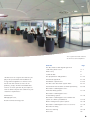
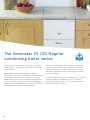
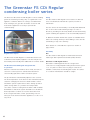
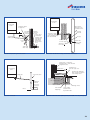
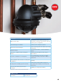
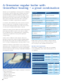
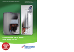
Technical and Specification Information Greenstar FS CDi Series Greenstar FS CDi gas-fired condensing regular floor standing boiler series 1 Worcester and you. Making a difference. 2 As part of the Bosch Group, Worcester supported by an experienced technical products are designed and manufactured to services team which is able to provide provide customers with the highest levels of comprehensive support and advice quality and reliability which are synonymous from designing system layouts through with the Bosch name throughout the world. to installation. As part of Europe’s largest supplier of Worcester is dedicated to providing energy heating products, Worcester, Bosch Group efficient gas- and oil-fired condensing has the UK-based resources and support boilers, as well as an extensive range of capability to offer you the value-added renewable technologies. All of our products solutions you deserve. Worcester employs have been developed and introduced with a nationwide network of Service Engineers the aim of helping the UK to achieve the and technically trained Field Sales Managers Government’s efficiency targets. The reception and main entrance at our Worcester headquarters Contents Page The Greenstar FS CDi Regular gas-fired condensing boiler series 4-7 Inside story 8 Technical data 9 Site preparations and guidance 10 - 11 Condensate pipework 12 - 13 energy efficient appliances in homes across Installation requirements 14 - 15 the UK. We will continue to invest in our The Worcester Greenstar System Filter 16 - 17 products, people, facilities and added value Horizontal and vertical flue terminal positioning 18 - 19 “At Worcester we recognise the vital role you play in the specification and installation of services to ensure you have all you require in order to deliver only the best solutions to your customers’ requirements.” Carl Arntzen, Managing Director, Bosch Thermotechnology Ltd. Greenstar FS CDi Regular series horizontal fluing options 20 - 21 Greenstar FS CDi Regular series vertical fluing options 22 - 23 Greenstar FS CDi Regular series flexible flue system for chimney installations 24 - 25 Plume management system options 26 - 29 Greenstar FS CDi Regular series accessories 30 - 31 Greenfloor heating 32 Worcester training 33 - 35 After-sales 36 3 The Greenstar FS CDi Regular condensing boiler series The Greenstar FS CDi Regular series is part of a market Greenstar FS CDi Regular condensing boilers deliver this leading range of energy-saving condensing floor standing energy-saving performance by recycling exhaust gases to gas-fired boilers. extract the latent heat – a highly efficient use of energy which also significantly reduces carbon dioxide emissions Higher efficiency therefore highly cost effective into the atmosphere. All of the new Greenstar FS CDi Regular condensing boilers are SEDBUK A rated. This means they have an average To all these major benefits you can add yet more: renowned annual efficiency of over 90%, standard efficiently boilers Worcester quality and reliability; a range of outputs to achieve around 78% efficiency. Therefore by upgrading to satisfy the heating demands of a range of households and a Greenstar FS CDi Regular boiler, consumers can reduce truly all-round value for money. their gas bills as well as their carbon footprint. 4 The Greenstar FS CDi Regular series at a glance FS 30CDi Regular FS 42CDi Regular Min 7.7 9.6 Max 30 40.8 Primary temperature control Natural gas Output kW to central heating (CH) Features Benefits SEDBUK Band A High efficiency Aluminium-silicon heat Lightweight with rapid exchanger heat transfer Robust heat exchanger More tolerant to existing systems Pre-fabricated pipe No pipe fabrication connections supplied required Multi-directional Condensfit II™ Siting flexibility LPG fluing – compatible with Electronic ignition 90.5% / A rated 90.3% / A rated 2005 SEDBUK value – natural gas plume management Flexible flue for chimney Ideal for replacement installation market where existing boiler uses chimney Fault finding diagnostics Time saving Operational status indicator Consumer friendly Anti-cycle control Energy saving Rigid 22mm gas connection No pre-forming of gas supply Built-in frost protection Money saving, economical protection Built-in condensate Increases siting pump – 4.5m head possibilities Roll-in boiler Minimises risk of damaging floors 5 The Greenstar FS CDi Regular condensing boiler series The Worcester Greenstar FS CDi Regular is a floor standing Fluing gas-fired condensing “heating only” or regular boiler. The The Greenstar FS CDi Regular series features 2 different appliance combines within one casing a cast-aluminium sizes of multi-directional RSF flue systems, 100mm or heat exchanger, fan, gas valve and other electronic and 125mm dia. mechanical equipment necessary to provide full central heating. The flue can be run horizontally or vertically with additional 90º or 45º in-line bends allowing changes of route or direction, providing an extremely flexible and versatile fluing system enabling the appliance to be sited virtually anywhere. Feed and expansion cistern Cold water storage cistern In addition an 80mm flexible flue system is available which utilises an existing chimney in the building to route the flue Hot water cylinder Hot water to baths, showers and basins etc Programmer terminating on top of the chimney. Pump Motorised valve Room thermostat Worcester regular boiler More details on our flexible flue system are shown on pages 24-25. Versatility Regular boiler layout Gas The Greenstar FS CDi Regular is manufactured in both The Greenstar FS CDi Regular is a multi-directional room natural gas and Liquid Petroleum Gas (LPG) variants. sealed fan assisted (RSF) appliance. The flue may be run horizontally and vertically with additional 90° and 45° bends. Greenstar FS CDi Regular boilers Greenstar FS CDi Regular boilers are designed for The Greenstar FS CDi Regular design benefits connection to a fully pumped heating and hot water system in operation i.e. S or Y plan. For this reason no plug-in controls are Whenever a demand for DHW or CH is made, the boiler’s available on Greenstar FS CDi Regular models. The advice electronic control system is activated and the burner of a controls manufacturer should be sought. electronically ignited via a flame ionisation system. The pre-mix burner automatically adjusts to the set level. The flow temperature of the boiler is then maintained at the customer setting by the fascia mounted variable control. Should the system requirements reduce during operation (TRVs closing down etc.), and the flow temperature exceed the customer setting then the burner will modulate downwards to match the system demand level. Should the flow temperature continue to rise then the burner will be de-energised and the control system will go into an anti-cycle mode and not allow the appliance to re-fire for a set period. 6 Controls Applications The Worcester Greenstar FS CDi Regular fascia incorporates • Greenstar FS CDi Regular boilers are suitable for a wide a combined temperature control and burner reset button. range of heating loads allowing extension to the heating system without upgrading the boiler The fascia also displays 2 operational status neons indicating the following: • Mains on/lockout • Burner on. • The Greenstar FS CDi Regular is capable of operating on both open vent and sealed primary water systems • Two or more Greenstar FS CDi Regular boilers can be linked together to cater for commercial or industrial applications • Using the new flexible flue system the Greenstar FS CDi is an ideal replacement for a floor standing boiler located near a fireplace and using a chimney liner to flue. The mains on/lockout indicator also operate as fault finding diagnostics flashing in different sequences in the unlikely event of a boiler fault. The Building Regulations Section L 2006 require a minimum level of controls to be installed on all heating systems, both on new build and refurbishment. This would require: • Room thermostat • TRVs on all radiators, or at least those radiators in sleeping areas if not already fitted. Do not fit TRVs in the room in which the room thermostat is installed • Time and temperature control for central heating • Automatic by-pass.* *Where requested – see installation booklet for further details. 7 Inside story – the Greenstar FS CDi Regular condensing boiler Pre-mix fan Down firing low NOx burner Aluminium/ silicon WB5 heat exchanger Air/gas adjustment screw Condensate pump assembly On/off button Temperature control 8 Digital display Technical data Model FS 30CDi Regular FS 42CDi Regular Height (mm) 850 850 Width (mm) 400 400 Depth (mm) 600 600 Weight – dry (kg) 55.1 55.1 2005 SEDBUK value – natural gas 90.5% / A rated 90.3% / A rated 2005 SEDBUK value – LPG 91.9% / A rated 91.1% / A rated 2009 SEDBUK value – natural gas 88.9% 88.8% 2009 SEDBUK value – LPG 89.9% 89.8% Heating flow / return connections 28mm compression 28mm compression Gas connection 22mm compression 22mm compression 88 88 7.7 - 30 9.6 - 40.8 (26,272 - 102,360) (32,755 - 139,210) Max. vertical flue (mm) (100mm dia.) inc. terminal 6,400 6,400 Max. vertical flue (mm) (125mm dia.) inc. terminal 15,000 15,000 Max. horizontal flue (mm) (100mm dia.) 4,000 4,000 Max. horizontal flue (mm) (125mm dia.) 13,000 13,000 NOx classification Class 5 Class 5 37 37 Max. flow temperature (ºC) Output to central heating Noise output level (dB(A)) kW (Btu) 9 Site preparations and guidance Greenstar FS CDi Regular boilers are designed for Service clearances connection to a traditional heating and hot water system. The minimum space required to service the boiler only. The major benefits of the Greenstar FS CDi Regular boiler are: 410mm 1,200mm • The boiler is compatible with S and Y plan systems • The boiler comes with a roll-in boiler tray and 15mm pre-plumbing jig. number of additional time-saving installation features: • Built-in frost sensor for boiler protection • Built-in fault finding diagnostics • Automatic gas pressure adjustment • Highly versatile multi-directional fluing system • Combined ignition and control board means fewer connections 5mm 865mm Greenstar FS CDi Regular boilers are exceptional for their 5mm 600mm 25mm* *25mm to a removable door Pipework connections and casing dimensions • A rigid 22mm compression gas connection eliminating the need for pre-fabricating the gas pipe onto the isolating valve 123mm • The large output range capability of the appliances. Siting of appliance A General The appliance is not suitable for external installation. The appliance may be installed in an airing cupboard if 28mm required. See section “Compartment Installation” on page 11. C B Clearances 22mm The following clearances should be allowed for installation Cabinet dimensions (mm) and servicing. A 850 Installation clearances B 400 The minimum space required to install the boiler only. C 600 1,200mm 410mm 1,450mm 600mm 5mm A B 5mm 600mm 10 Pipework connections A CH flow 22mm B Gas inlet 22mm C CH return 22mm C Compartment installation Boiler location & clearances The appliance may be installed in any room, although Bathrooms particular attention is drawn to the requirements of the IEE regulations applicable and in Scotland the electrical IMPORTANT: provisions with respect to installation in a room containing Any switch or appliance control using mains electricity must a bath or shower. not be within reach of a person using the bath or shower. Air supply Electrical switches, fused spurs and socket outlets must not 1. The room in which the appliance is installed does not be situated in the bathroom. require a dedicated air vent. A boiler fitted with a non-mechanical timer or with no timer 2. If the appliance is installed in a cupboard or can be installed in zone 2 or outside the shaded area. compartment with dimensions that allow the following minimum clearances, then no ventilation is required: A boiler with a mechanical timer or RF mechanical timer with a room thermostat must only installed outside the Compartment installation Position of appliance Min. unventilated clearance (to removable door) In front 200mm Right side 100mm* Left side 100mm* Above 50mm shaded area. Additional Residual Current Device (RCD) protection may be required. Refer to the latest IEE wiring regulations. *This space can be reduced to 50mm for one side only as long as both the side clearances add up to the total of both of the side measurements shown or more. 600mm 600mm 600mm 600mm 750mm 750mm 800mm 600mm 2 1 1 2 2,250mm 2 1 1 2 2,250mm 2,250mm 50mm 900mm 2,250mm 100mm** 200mm* 100mm** 600mm 600mm *Space required for unvented areas with a removable door or panel. **This space can be reduced to 50mm for one side only as along as both the side clearances add up to the total of both the side measurements shown or more. 750mm 750mm 2,250mm 2,250mm 2 1 1 2 2 1 1 2 2,250mm 2,250mm 600mm radius 600mm radius 11 Condensate pipework All condensing boilers generate condensate discharge The condensate connection on Worcester appliances is in which needs to be piped away from the appliance using a 22mm polypropylene. The pipe should be extended and run plastic pipe. away from the appliance with a constant fall of 3º or at least 50mm in every metre away from the boiler. The amount of condensate generated depends on the efficiency and operating status of the appliance. Depending The condensate pipe can terminate into any one of on operating temperatures, the appliance will condense in four areas. both heating and hot water modes and may generate up to 2.7 litres of condensate per hour for the FS 30CDi Regular Whilst all of the methods are acceptable it is best practise and 3.7 litres per hour for the FS 42CDi Regular. to terminate the condensate pipe via an internal waste system. This will eliminate the need for any external Condensate termination and route condensate pipe runs which can be susceptible to freezing Greenstar FS CDi Regular boilers incorporate a condensate in extreme weather. Best practise is not to run external pump which allows condensate to be plumbed above the condensate pipe any further than 3m. If it is necessary to boiler, allowing more flexible siting possibilities. run more than 3m externally increase pipe size to 32mm. Condensate connection Condensate termination and route The condensate pump fills up and periodically discharges External condensate pipework through the flexible condensate pipe between 200mm and The Worcester Greenstar FS CDi Regular appliances have a 4,500mm from floor level. After this point the condensate condensate pump rather than a syphonic condensate trap. continues down the 22mm rigid pipework to the outlet Rather than the condensate constantly dripping into the using gravity. discharge pipe, the condensate is collected in the pump which releases it in 100ml quantities. This will help prevent freezing occurring. Wherever possible the condensate discharge pipework should be routed and terminated internally. Should this not be possible, and the only available route is external, the Cut off excess pipework following conditions should be observed: Max. 4,500mm • The pipework length should be kept to a minimum and the route as vertical as possible • Where pipework could be subjected to extreme cold or wind chill, a weather proof insulation should be Min. 200mm used. Alternatively, the condensate pipework could be increased to a minimum 32mm. Condensate pump For full technical information on pipe size, insulation • The flexible plastic pipe can be reduced in length to suit the installation circumstances. The pipework must follow see Installation, Commissioning and Servicing one of the options shown opposite. Instruction Manual. Never terminate or discharge into any open source, including: sink, bath, shower, bidet, toilet etc. Note: any external condensate pipework should be protected with weather resistant insulation to help prevent freezing. 12 and different condensate pipework methods please level Bottom of tube sealed Drainage holes Limestone chippings 75mm sink waste trap Hole depth 400mm min. by 300mm dia. Condensing Condensing boiler boiler Condensing boiler Visible air break at plug hole Condensing boiler 100mm 75 mm min. 22mm dia. plastic pipe 22mm dia. Sink with Visible air break integral at plug hole overflow 100mm 22mm dia. plastic pipe External rain water pipe into & vent foulSoil water sewerstack Sink with integral overflow 75 mm 75mm sink min. waste trap Insulation or increase pipe size Open end of condensate Insulation drainage pipe or increase directly into pipe size gully below Open end grating but of condensate above water drainage pipe level directly into gully below grating but above water level 75mm sink waste trap External air break 22mm dia. plastic condensate drainage pipe running through the external wall Air gap Minimum 450mm and up to 3 dia. storeys 68mm Insulation or increase pipe size PVC-u strap on fitting 43mm 90° M & F bend Invert External air break when using a foul water down pipe Internal sink/washing machine drain 22mm dia. condensate drainage pipe, max external length 3 metres Condensing boiler Condensing boiler Soil & vent stack 22mm dia. Insulation or increase pipe size 500mm min. Condensate drainage pipe can be run above or below ground Soil & vent stack 22mm dia. Minimum 450mm and up to 3 storeys Minimum 450mm and up to 3 storeys Invert 25mm Diameter 100mm min. plastic tube Bottom of tube sealed Drainage holes Limestone chippings Invert Soil and vent stack Hole depth 400mm min. by 300mm dia. External condensate absorption point (unsuitable for clay soil types) 22mm dia. condensate drainage pipe, max external length 3 metres Insulation or 22mm increase pipe size 500mm min. dia. condensate drainage pipe, max external length 3 metres Condensate drainage pipe can be run above Insulation or ground or below increase pipe size 500mm min. Diameter 100mm min. plastic tube Bottom of Condensate drainage pipe can be run above 25mm or below ground Condensing boiler Externa water p foul wa 13 Ext Installation requirements Installation of the Greenstar FS CDi Regular Series must The following is a list of major items which must be fitted to be in accordance with the relevant requirements of the the system: Gas Safety (Installation Use) Regulations at the time of 1. Safety valve – 3bar installation, current IEE Wiring Regulations, local Building 2. Pressure gauge – 0 - 4bar Regulations, Building Standards (Scotland) regulations 3. Expansion vessel and bylaws of the local Water company and Health and 4. Automatic air vent Safety Document No. 635 (Electricity at Work Regulations 1989). It should be in accordance with the relevant Typical fully pumped sealed system Plastic pipework recommendations of the following British Standards: BS 6798; BS 5449; BS 5546:1; BS 5440:1; BS 5440:2; BS 6891. Gas Safety (Installation and Use) Regulations. All gas appliances must be installed by a Gas Safe registered person in accordance with the above regulations. Failure to install appliances correctly could lead to prosecution. The use of plastic pipework is acceptable. However, some The manufacturer’s notes must not be taken in any way as plastics are permeable to oxygen and must be avoided. Only overriding statutory regulations. pipework with a polymeric barrier should be used. Please note that the first 600mm of pipework connected to the Sealed primary systems boiler must be of copper. The appliance is fitted with a manual reset high limit thermostat and is suitable for use with a sealed Open vented primary systems primary system. Greenstar FS CDi Regular boilers are designed for connection to an open vented fully pumped heating and hot The system should be installed in compliance with the water system. requirements of BS 5449: Part 1. The boiler must be fitted with a spring loaded safety valve set to operate at 3bar The following points are for guidance only. The system (45 psi) and the pipe connections made through the system installation should be carried out in accordance with must be capable of sustaining a pressure of up to 3bar. BS 5449:Part 1. Manual air vents should be fitted at any high points in The feed and expansion pipes must rise continuously the system. from the appliance and must be of the minimum diameter shown below. The cistern must be arranged to provide a minimum static head of 0.25 metres above the top of the highest point in the heating circuit. Air in the appliance is expelled through the vent pipe or dissipated into the system. Manual air vents should be fitted at any high points in the system. 14 Total length of gas supply pipe (m) Air supply The Worcester Greenstar FS CDi Regular is a room sealed 3 6 9 – Gas 1.5 1.01 – 15 discharge 8.0 5.2 4.2 22 rate m3/h 15.9 8.9 8.3 28 appliance; the room in which it is installed does not therefore require a purpose provided combustion air vent. Natural gas supply The appliances when on full output demand will require up to 3.27m3/h (FS 30CDi) or 4.4m3/h (FS 42CDi) of gas. The Pipe diameter (mm) Approximate additional length to be allowed (LPG) gas meter and supply pipes must be capable of supplying this quantity of gas in addition to the demand from any other appliance being served. Under no circumstances should the size of the gas supply pipe be less than that of Elbows or tees Metres 0.6 Feet 2 90º bends Metres 0.3 Feet 1 the appliance inlet connection (22mm diameter). The meter outlet governor should be capable of ensuring a dynamic Electricity supply nominal pressure of 20mbar (8in wg) at the appliance. A 3 amp fused three pin plug and unswitched shuttered Particular consideration should be given to the resistance socket outlet (both complying with BS 1363) or preferably a to gas flow created by elbows, bends etc. Pipework should double pole isolator with a contact separation of 3mm in all be sized to overcome this resistance, and details of this are poles supplying the appliance should be used. given in the following table. The appliance electrical circuits are also protected by an Total length of gas supply pipe (m) Pipe diameter (mm) internal 2.5 amp fuse. The appliance must be earthed. 3 6 9 – Guarantee Gas 2.9 – – 15 Worcester Greenstar FS CDi Regular appliances are offered discharge 8.7 5.8 4.6 22 with a full 2 year guarantee* on parts and labour, a 10 year rate m3/h 18.0 12.0 9.4 28 guarantee* on the primary heat exchanger and a 5 year guarantee* on the plate heat exchanger. Ongoing service Approximate additional length to be allowed (natural gas) Elbows or tees Metres 0.5 Feet Worcester Customer Service Department. 90º bends Metres 2 0.3 and maintenance contracts can be arranged through the Feet Please contact our guarantee registration advisors on 1 0844 892 2552 or visit www.worcester-bosch.co.uk/ guarantee Liquid Petroleum Gas (LPG) supply The Greenstar FS CDi Regular appliance is available in an LPG version. The appliance, when on demand at full output will require 2.3kg/h for the FS 30CDi Regular and 3.3kg/h for the FS 42CDi Regular. The gas tank or bottles must be capable of supplying this quantity of gas at a nominal pressure of 37mbar (14.8in wg) at the appliance. The table below shows the LPG discharge through varying lengths of pipe and the resistance to flow created by elbows, bends etc. Pipework should be sized to overcome this resistance. *Subject to conditions. 15 The Worcester Greenstar System Filter Modern condensing boilers are precision engineered and A highly effective solution from the brand you can trust designed to run with a clean water heating system. Over The Worcester Greenstar System Filter has been specifically time, dirty system water will damage a boiler and its designed to combat the damaging effects of system debris components, causing failures and shortening the life of the and pollutants, allowing homeowners to protect their boiler overall system. or heat pump for a fraction of its cost. The filter is suitable for 22mm piped heating systems. Damaged boiler and system components • Blockages in primary heat exchanger • Increased wear on pumps • Blocked valves. At the centre of this innovative design is a highly powerful magnet that removes the magnetic debris (magnetite) that is present in the heating system water. The central location of the magnet ensures that magnetite is collected quickly and retained, maximising the overall protection. Any non-magnetic debris is caught by the twin-action cyclonic trap, a proven technology that offers a capacity to collect up to 200g of magnetite a year. The Greenstar System Filter has been extensively tested in simulated systems, proving its effectiveness in removing: iron oxide, magnetite, limescale particles, casting sand, welding debris, non-magnetic metal flakes, paint particles and other system pollutants. Heat exchanger damaged by system debris and pollutants Reduced efficiency • Energy efficiency loss equivalent to a boiler being reduced from A rated efficiency to D rated, resulting in fuel wastage • Blocked radiators can reduce efficiency and heating comfort. A thermal graphic of a blocked radiator Debris in the system blocks the efficient flow of water around the system, thus affecting the radiator’s heat distribution. 16 The Greenstar System Filter is easy to install and service Installation The filter can be installed almost anywhere in a heating system, however to maximise the effectiveness it should be placed before the boiler and after the last radiator. NEW Features Benefits Safeguards the boiler against damage and Highly effective filter protects the efficiency of the system. Saves up to 6% a year on energy bills* Prevent blockages in radiators A warmer home and quieter system Proven technology that can capture up to 200g High powered internal magnet of magnetite Increased performance – better installation Cylindrical design options Twin-action – magnetic and non-magnetic Instantly effective against a wide range of filtration system debris No electrical wiring connection or supply No power consumption or moving parts needed. Zero running costs and no failure of components Can be installed under the boiler or away from the appliance Flexibility Removes the need to isolate a section of One-way valve for adding system chemicals the system when carrying out servicing and maintenance Worcester, Bosch Group specification and design Reliability of components and filter *Independent research carried out by GASTEC at CRE Product info Part number 7 716 192 609 17 Horizontal and vertical flue terminal positioning All measurements in millimetres 2 25 3 1,500 600 2 1 5 300 300 1,500 600 1,200 4 6 Boundary Line Note Key to illustration • All measurements are the minimum clearances required • Terminals must be positioned so to avoid combustion products 1. 300mm adjacent to a boundary line. 2. The dimension below eaves, balconies and car ports can be • entering the building reduced to 25mm, as long as the flue terminal is extended to Support the flue at approximately one metre intervals and at a clear any overhang. External flue joints must be sealed with change of direction, use suitable brackets and fittings. suitable silicon sealant. Flue bracket part numbers: 3. 1,500mm between a vertical flue terminal and a window or dormer window. 7 716 191 092 (100mm dia.) 7 716 191 173 (100mm dia. x 6) 4. 1,200mm between terminals facing each other. 7 716 191 174 (125mm dia.) 5. Vertical flue clearance, 300mm adjacent to a boundary line. 6. 600mm distance to a boundary line, unless it will cause a nuisance. BS 5440:Part 1 recommends that care is taken when siting terminal in relation to boundary lines. 7. 600mm minimum clearance from a skylight to a vertical flue. 8. Vertical flue clearance, 500mm to non-combustible building material, and 1,500mm clearance to combustible 18 building material. 2m 1m 25 104mm 52mm 16 13 300 400 500 12 14 200 300 7 8 600 500 300 300 15 300 600 9 600 10 11 300 300 16 17 300 300 25 300 9. 18 300 300mm above, below and either side of an opening door, air vent or opening window. 10. 600mm diagonally to an opening door, air vent or opening window. 11. 300mm to an internal or external corner. 12. 2,000mm below a Velux window, 600mm above or to either side of the Velux window. 13. 400mm from a pitched roof or 500mm in regions with 17. Flue clearance must be at least 300mm from the ground. Terminal guards must be fitted if the flue is less than 2 metres from the ground or if a person could come into contact with the flue terminal. 18. 600mm distance to a surface facing a terminal, unless it will cause a nuisance. BS 5440: Part 1 recommends that care is taken when siting terminals in relation to surfaces facing a terminal. heavy snowfall. 14. 500mm clearance to any vertical structure on a roof, 600mm to room sealed flue or 1,500 to an open flue. 15. 200mm below eaves and 75mm below gutters, pipe and drains. 16. The dimension below eaves, balconies and car ports can be reduced to 25mm, as long as the flue terminal is extended to • Installations in car ports are not recommended • The flue cannot be lower than 1,000mm from the top of a light well due to the build up of combustion products • Dimensions from a flue terminal to a fanned air inlet to be determined by the ventilation equipment manufacturer. clear any overhang. External flue joints must be sealed with suitable silicon sealant. 19 Greenstar FS CDi Regular boiler series horizontal fluing options Greenstar FS CDi Regular boilers offer a choice of 2 different The following criteria should be noted when planning the sized horizontal RSF flue systems, 100mm diameter and installation. 125mm diameter. The systems have different maximum • The concentric flue system must be inclined at 3º lengths. Options 1 to 8 detail the permissible lengths. (52mm per metre) from the appliance, to allow condensate to drain back into the boiler. • Because the appliance operates at high efficiency a Horizontal RSF flue white plume of condensation will be emitted from the Flue diameter 100mm 125mm terminal. Care must be taken when selecting the flue terminal position (see pages 18-19). Minimum flue length 130mm 350mm Maximum flue length 4,000mm 13,000mm Option 1 Extension rear flue horizontal flue assembly 100mm dia. telescopic flue kit Comprises: 1 x internal flue connector bend 1 x flue adaptor 1 x flue connector 2 x wall cover plates 530mm (100mm dia.) of flue duct including terminal Part No. 7 716 191 155 Components required 125mm dia. standard flue kit Maximum length (m) 1 x internal flue connector bend 60/100 4 1 up to 4 1 x flue adaptor 80/125 13 1 up to 12 1 x flue connector 2 x wall cover plates Option 2 965mm (125mm dia.) of flue duct including terminal Extension rear flue horizontal using a 90º bend Part No. 7 716 191 157 Accessories Components Part no. Description 60/100 530mm 7 716 191 155 Horizontal telescopic kit 7 716 191 083 60/100 1m extension 7 716 191 084 60/100 90º bend Components required Maximum length (m) 7 716 191 085 60/100 45º bend 60/100 PiPtcitc h he r2.5 oroofof ed d 1 up to 2 1 1 up to 10 1 500mm 500mm 7 716 191 133 60/100 Short flue extension Pi80/125 tc roo hed f 7 716 191 164 60/100 Vertical flue adaptor Pitc Deduct total flue length for every he 750mm off theFlat roof Min. Min. 120mm 120mm 7 716 191 157 80/125 965mm Horizontal flue kit Min. 120mm 7 719 003 666 80/125 1m extension Pitc roo hed f 7 719 003 664 80/125Min. 90º bend 120mm 20 Min. d Min. Min. Min. 120mm Min. Pitc 120mm hed 120mm 120mm r oof 500mm Flat roof Flat roof 300mm 300mm M 1 300mm 45º bend used. 500mm Deduct 1,500mm off the total flue length for every P itc bend 90º roo hed f Pitc roo hed f Pitc roo hed f Flat roof 300mm used. 500mm 300mm 7 719 003 665 80/125 45º bend Min. Min. 120mm 120mmflue adaptor 7 716 191 165 80/125 Vertical *The 100mm flue system inclines 2º within the 100mm terminal. roo f 11 Min. 120m 500mm Flat roof 300mm P Pitcitche d r roooofhed f 500mm 300mm 500mm 500mm Flat roof 500mm 500mm 300mm 300mm Flat roof Flat roof Flat roof Min. 120mm c roo hed f 500mm Fla 300mm Min. 120mm Pitc roo hed f 500mm Fla 300mm Option 3 Option 6 Min. Min. 120mm flue upwards and horizontal 120mm Extension using a second 90º bend Extension rear flue horizontal using 45º bends Min. 120mm Pitc roo hed f Min. 120mm Min. 120mm Components required Maximum length (m) 60/100 2.5 1 up to 2 2 80/125 11 1 up to 10 2 Min. 120mm Option 4 Extension rear flue horizontal using a second 90º bend Min. 120mm Components required Maximum length (m) Pitc heP 60/100 1 80/125 9 1 Min.roof ditche 120mm ro up to 2 2of d 500mm 1 P itch 1 roof ed up to 8 2 300mm 1 500mm Min. 120mm 300mm Min. 500mmPi Flat roof tch 300mm Min. ed roo Fla f Flat roof 120mm Option 7120mm Min. 120mm Min. 120mm Pitc roo hed f Extension flue upwards and horizontal Min. using a third 90º bend 120mm Min Min. 120 120mm Min. 120mm required Components Maximum length (m) Min. 120mm 60/100 1 1 up to 2 2 80/125 9 1 up to 8 2 Min. 120mm Min. 120mm Min. 120mm Min. Maximum length (m) 60/100 N/A Min. 80/125 120mm Min. 120mm Pitc P it roo hreod ched f of 500mm 500mm Pitc Min. Min. required 300mm Flat Min. roof roo hedComponents Flat ro f 120mm300mm 120mm 120mm 500mm Option 5120mm Extension flue upwards and horizontal M 12 Min. Min. 120mm 120mm 7 Min. 300mm 120mm M 12 Flat roof N/A N/A N/A 1 up to 6 3 Min. N/A 120mm 1 Option 8 Side flue extension using two 45º bends Components required Maximum length (m) Min. 120mm Min. 120mm 60/100 2.5 1 up to 2 1 1 80/125 11 1 up to 10 1 1 Min. Min. 120mm 120mm Min. 120mm Maximum length (m) Min. 120mm 60/100 Min. 120mm Min. 120mm Min. 120mm 2.5 Min. Min. Min. 80/125120mm 11 120mm 120mm Min. 120mm Min. Pitc 120mm roo PPhiite ccdhe t rrfooo hedd required Components off 500mm Min. Min. Min. 500mm 500mm 120mm 120mm Pitc 120mm Flat roof 300mm h Flat roo ed 300mm Flatroof roof 300mm f Min. 1 up to 2 2 500mm 120mm M 1 up to 10 Flat roof 2 300mm Min. 12 Min. 120mm Min. Min. 120mm 120mm 120mm Min. 120mm 21 Greenstar FS CDi Regular boiler series vertical fluing options Greenstar FS CDi Regular boilers offer a choice of 2 Accessories different sized vertical RSF systems, 100mm diameter and 125mm diameter. Both systems have different maximum Components Part no. Description 7 716 191 156 60/100 Vertical 1,140mm kit lengths. Options 1 to 3 detail the permissible lengths. 7 716 191 083 60/100 1m extension Vertical RSF flue 7 716 191 084 60/100 90º Pitcbend h Flue diameter Flue terminal assembly diameter Maximum flue length (inc. terminal) Flue terminal assembly length 100mm roo ed f 125mm 120mm 135mm 6,400mm 15,000mm 1,140mm 1,365mm 7 716 191 085 60/100 45º bend 500mm Flat roof 300mm 7 716Min. 191 133 60/100 Short flue extension 120mm Pitc roo f 7 716 191 158 80/125 Vertical 1,365mm kit Pitc roo f 7 719 003 666 80/125 1m extension Min. 120mm Min. 120mm Vertical balanced flue kit Pitcbend 7 719 003 664 80/125 90º h roo ed f Comprises: 7 719 003 665 80/125Min. 45º bend 120mm 1 x flue terminal assembly 1 x weather sealing collar Pitc roo h f 500mm 300mm Flat roof Min. 120mm Min. 120mm 1 x fire stop spacer Pitc roo f Min. 120mm 1 x vertical flue adaptor 1 x wall bracket Min. 120mm 1 x flue adaptor Min. 120mm Part No. 7 716 191 156 (100mm dia.) Part No. 7 716 191 158 (125mm dia.) Min. 120mm Min. 120mm Min.Min. 120mm 120mm Min. 120mm Min. 120mm Min. 120mm Min. 120mm Min. 120mm Min. 120mm Min. 120mm Min. 120mm Min. 120mm Min. 120mm Min. 120mm Min. 120mm Min. 120mm Min. 22 120mm Min. 120mm Min. Min. 120mm Pitc roo h f Min. 120mm Option 1 Option 3 Vertical balanced flue assembly Vertical balanced flue using two 90º bends Pitc roo hed f 500mm Flat roof 300mm Pitc roo hed f Min. 120mm 500mm Flat roof 300mm Min. 120mm Maximum length (m) 60/100 6.4 1 up to 6 80/125 15 1 up to 14 Pitc roo hed f 60/100 3.4 1 up to 3 80/125 11 1 up to 10 2 2 Pitc roo hed f 500mm Pitc roo hed300mm f 500mm 300mm Option 2 Components required Maximum length (m) Components required Min. 120mm Flat roof Flat roof 500mm 300mm Min. 120mm Vertical balanced flue using two 45º bends Min. 120mm Min. 120mm Min. 120mm Min. 120mm Min. 120mm Min. 120mm Min. 120mm Min. 120mm Components required Maximum length (m) 60/100 4.9 1 up to 5 80/125 13 1 up to 12 Min. 120mm Min. 120mm Min. 120mm 2 2 Pitc roo hed f 500mm 300mm Min. 120mm Flat roof Min. 120mm Pitc ditc roo heP h f roo ed 500mm f 500mm Min. 120mm 300mm Min. 120mm Flat roof Fla 300mm Min. 120mm Min. 120mm Min. 120mm Min. 120mm Min. 120mm Min. 120mm Min. 120mm Min. Min. 120mm 120mm 23 Greenstar FS CDi Regular series flexible flue system for chimney installations Greenstar FS CDi Regular boilers can be used with a flexible flue system which utilises an existing chimney in the building to route the flue terminating on top of the chimney. It is available in one size – 80mm diameter and 12m length. The A flexible liner can be cut down from the 12m length to suit. 80mm flexible flue system B Comprises: 1 x flue terminal (A) C 1 x chimney cowl (B) 1 x self-adhesive weather seal (C) D 1 x support bracket assembly (E) E 2 x liner (F) F 2 x seal (G) G 1 x flexible liner (H) H M 1 x support bend adaptor (J) 1 x support bend (K) 1 x bend support (L) 2 x flue inspection plates (M) I Q R O 1 x 125mm flue extension (O) 1 x tee piece (P) J 1 x 125mm flue connector (Q) Part No. 7 716 191 159 P K Q R Flexible flue terminal clearances L The same clearances apply as for the vertical flue as shown in the flue terminal positioning diagram on pages 18 and 19. Requirements for the chimney The flexible flue system is designed to be installed through a hole in the side of the chimney as shown in the diagram opposite. This will necessitate cutting a hole 150mm min./260m max. width and 360mm min./390mm max height into the chimney. To avoid debris falling into the air inlet duct, do not install the duct with the open end facing up the chimney. Requirements for the chimney 24 P N 1 x seal for flue inspection plates (N) 1 x 80/80mm flue adaptor (R) N O 1 x terminal adaptor (D) 4 x centralising spacers (I) M Chimney size Calculating the effective flue length Ensure the cross section of the chimney complies with the diagram and table below. dia. d c 45º bends Lv Chimney size (mm) ‘c’ min ‘c’ max ‘dia. d’ min 130 300 146 ‘dia. d’ max 300 Lh Calculating the effective flue length Fire resistance The materials used for the construction of the chimney must be fire resistant in compliance with the figures Appliance Max. flue length vertical (Lvmax) Max. flue length horizontal (Lhmax) FS 30CDi 12m 3m FS 42CDi 12m 3m stated below. Type of building Fire resistance Single storey 30 minutes Multi-storey 90 minutes To calculate the effective flue length: • Check the flue path and consider the following: – number of 90° and 45° bends required outside Preparing the chimney • The chimney must be swept if it has been previously used • It is recommended that the chimney be swept before for an appliance burning a fuel other than gas installation of the flexible flue • Any damper or restrictor plate in the chimney must be the chimney – number of bends in the flexible liner • Deduct the effective length of each bend from the maximum horizontal flue length of 3m 80/125mm bend Effective length (m) removed. If it is not possible to remove the sliding damper 90º 2 it must be fixed permanently in the open position 45º 1 • Any holes in the chimney must be sealed • The existing chimney pot and flaunching must be removed • The catchment space (void below the point of flue • Deduct the effective lengths of each bend from the maximum vertical flue length (Lvmax) of 12m. connection) must be checked to ensure it complies with the flue to be installed • All debris must be cleared from the catchment space Bend in 80mm flexible liner 45º Effective length (m) 1.5 Example of effective flue length calculation This example shows the use of the flexible flue kit without additional extensions or bends. Horizontal effective flue length (no extensions or bends) Lh = 1m Lh ≤ Lhmax ? Lhmax = 3m Vertical effective flue length (with 2 x 45º bends) Lvmax = 12m - 2 x 45º bends = 3m = (12 - 3) Yes Lv 9m 25 Plume management terminal positioning All measurements in millimetres 180° Flue terminal guard 7 716 191 176 ±45° Plume re-direction: 600 1 Flue exhaust outlet 100 10 1,500 Air intake ±80° 6 200 300 2 200 5 600 150 200 300 300 3 150 300 300 150 1,200 150 300 300 7 150 25 300 8 25 200 600 9 10 4 Boundary line Note 6. • All measurements are the minimum clearances required • Refer to pages 18-19 for all concentric flue terminal positions be reduced to 150mm providing the flue exhaust outlet has a 300mm clearance. Plume kits running horizontally must have a unless the flue position is specified on the figure above 10° fall back to the boiler for proper disposal of condensate. “Plume terminal positions” For details on specific lengths see relevant boiler Technical & • Terminals must be positioned so to avoid combustion products entering the building Specification information. 7. • Support the flue at approximately one metre intervals and at a 300mm clearance. 8. Key to illustration This feature allows some basic plume re-direction options on a standard telescopic horizontal flue terminal. 300mm minimum clearances to a opening e.g. window. However the Internal/external corners. The air intake clearance can be reduced to 150mm providing the flue exhaust outlet has a change of direction, use suitable brackets and fittings. 1. Using a Plume Management kit the air intake measurement can Clearances no less than 200mm from the lowest point of the balcony or overhang. 9. 1,200mm from an opening in a car port on the same wall e.g. door or window leading into the dwelling. 10. 600mm distance to a surface facing a terminal, unless it will minimum clearances to an opening in the direction that the cause a nuisance. BS 5440: Part 1 recommends that care is plume management is facing, must be increased to 1,500mm. taken when siting terminals in relation to surfaces facing Where the flue is less than 150mm to a drainpipe and plume a terminal. re-direction is used the deflector should not be directed towards the drainpipe. 2. 300mm adjacent to a boundary line. 3. Plume Management kit air intake can be reduced to 150mm providing the flue exhaust outlet is no less than 300mm adjacent to a boundary line. 4. 1,200mm between terminals facing each other. 5. 600mm distance to a boundary line, unless it will cause a nuisance. BS 5440:Part 1 recommends that care is taken when siting terminal in relation to boundary lines. 26 • Installations in car ports are not recommended • The flue cannot be lower than 1,000mm from the top of a light well due to the build up of combustion products • Dimensions from a flue terminal to a fanned air inlet to be determined. Plume management system options Plume management system Re-directing flue discharge from a 60mm dia. 60mm dia. plume management kit plume management outlet Comprises: 1 x terminal bend 1 x extension 500mm 1 x outlet assembly Min. 1,500mm 1 x clamp pack Opening in building e.g. window Part No. 7 716 191 086 Direction of flue discharge Accessories Components Part no. Description Direction of 60mm dia. 7 716 191 086 Plume management kit flue discharge 7 716 191 087 60mm dia. Extension (1,000mm) Min. 1,500mm L 7 716 191 088 60mm dia. 90º Bend Opening in building e.g. window 7 716 191 089 60mm dia. 45º Bend (pair) Standard plume management system The flue terminal outlet has built-in stops to limit rotation Condensfit II™ telescopic flue and plume management for horizontal fluing to allow condensate to run back into system measuring the boiler for safe disposal. Do not attempt to force beyond the limit stops. Fig A All plume management sections must rise by at least 173mm per metre (10º) from the terminal to ensure that condensate flows back into the boiler. L (max) 500mm (min) (M) Fig B 500mm (M) 4,500mm (max) (M) L (max) 27 Effective straight flue lengths for telescopic flue with plume management Model Fig. A Fig. B Max. straight flue Max. straight flue length (L) with min. length (L) with max. plume management plume management length (M)* (mm) length (M)* (mm) FS 30CDi Regular** 4,000 1,200 FS 42CDi Regular** 4,000 1,200 Condensfit II™ telescopic flue and plume management system measuring 100mm dia. horizontal telescopic flue lengths with a 60mm dia. plume management system The maximum effective straight flue lengths (L) are stated opposite for the relevant appliance together with the minimum and maximum lengths (M) of the plume management system connected, these lengths must not be exceeded. 60mm dia. plume management system NOTE: To ensure that the maximum total straight flue length along Plume management minimum straight length = 500mm the plume management route is not exceeded the following Plume management maximum straight length = 4,500mm should be added to dimension (M): **For every additional 1,000mm of plume management length (M), reduce flue length (L) by 700mm – see figures A and B. • 1,500mm for each extra 90º bend • 750mm for each extra 45º bend For plume management options with 60mm dia. extensions refer to page 29. Note: For information on the Condensfit II™ Telescopic Flue System and Plume Management Kit, please see dedicated flue Technical and Specification leaflet 8 716 112 174. Flue length ‘L’ versus plume management kit Effective internal flue length ‘L’ (mm) 4000 3500 3000 2500 2000 1500 1000 500 700 900 1100 1300 1500 1700 1900 2100 2300 2500 2700 2900 3100 3300 3500 3700 3900 4100 4300 4500 Plume management length allowed ‘M’ (mm) Use the graph above to determine the permissible plume The effective flue length can be determined by adding management length that can be used with your effective together all the straight flue lengths and the effective flue length ‘L’. lengths of the bends used, 1,500mm for each 90º bend and 750mm for each 45º bend. 28 Plume management options See tables below for details of components required. Option 1 Option 4 Plume management system Plume management system with angled termination Components required Maximum length (mm) Greenstar FS CDi Regular series 60mm 500* 1 Option 2 Plume management system with extensions Components required Maximum length (mm) Greenstar FS CDi Regular series 60mm 4,500* 1 up to 4 Option 5 Plume management system with extensions and 45º bends Components required Maximum length (mm) Greenstar FS CDi Regular series 60mm 4,500* 1 up to 4 Option 3 Plume management system with extensions and 45º bend Components required Maximum length (mm) Greenstar FS CDi Regular series 60mm up to 3 2 *NOTE: You must refer to the table on page 28 to calculate Greenstar FS CDi Regular series 3,750* 1 Components required Maximum length (mm) 60mm 3,000* 1 up to 4 1 your horizontal flue lengths and plume management length. 29 Greenstar FS CDi Regular series accessories RS telescopic flue kit (100mm dia.) Horizontal flue kit (125mm dia.) Vertical BF kit (100mm dia.) Vertical BF kit (125mm dia.) Worcester Part No. 7 716 191 155 Worcester Part No. 7 716 191 157 Worcester Part No. 7 716 191 156 Worcester Part No. 7 716 191 158 Vertical flue adaptor (60/100mm) Vertical flue adaptor (80/125mm) 1,000mm extension kit (100mm dia.) Short flue extension 220mm (100mm dia.) Worcester Part No. 7 716 191 164 Worcester Part No. 7 716 191 165 Worcester Part No. 7 716 191 083 Worcester Part No. 7 716 191 133 1,000mm extension (125mm dia.) 45º bend (100mm dia.) 45º bend (125mm dia.) 90º bend (100mm dia.) Worcester Part No. 7 719 003 666 Worcester Part No. 7 716 191 085 Worcester Part No. 7 719 003 665 Worcester Part No. 7 716 191 084 Note: For information on the Condensfit II™ Telescopic Flue System and Plume Management Kit, please see dedicated flue Technical and Specification leaflet 8 716 112 174. 30 90º bend (125mm dia.) Support bracket kit (100mm dia.) 80mm flexible flue system Plume management kit (60mm dia.) Worcester Part No. 7 719 003 664 Worcester Part No. 7 716 191 092 Worcester Part No. 7 716 191 159 Worcester Part No. 7 716 191 086 Extension (60mm dia., 1,000mm) 90º bend (60mm dia.) 45º bend (60mm dia.) Flat roof flashing kit (100mm & 125mm dia.) Worcester Part No. 7 716 191 087 Worcester Part No. 7 716 191 088 Worcester Part No. 7 716 191 089 Worcester Part No. 7 716 191 090 Pitched roof flashing kit (100mm & 125mm dia.) Greenstar System Filter Worcester Part No. 7 716 191 091 Worcester Part No. 7 716 192 609 31 A Greenstar regular boiler with Greenfloor heating – a great combination Whether you are upgrading an existing system or installing a new system, Worcester Greenfloor heating can provide an ideal alternative to traditional radiators. Worcester’s Greenfloor heating system uses a water-filled pipe system that turns the floor into a large surface area radiator. The pipe system gently warms the space above it through a combination of radiant energy and heat conduction. In a modern, well-insulated space where heat loss factors have been taken into consideration, underfloor heating can act as the primary heating source and, in most cases, Features Benefits PE-Xc Pipe, protected against thermal ageing and stress fracture Flexible and durable Pre-insulated pipe positioning panels Quick and easy installation Stainless steel manifolds Robust and durable Full suite of wireless and wired control systems Suits any type of installation Uses radiant heat Less circulation of dust than with radiators, cleaner air for home Requires lower working temperatures Maximises the efficiency of condensing boilers and heat pumps Eliminates the need for radiators Creates space on walls and allows unrestricted layout within a room Complements Worcester gas- and oil-fired boilers, ground source and air to water heat pumps Complete heating and hot water solutions from one source no other space heating methods will be required. Underfloor heating operates with lower water temperatures than traditional radiator systems. This makes it suitable for use with Worcester condensing boilers, ensuring they remain at their optimum efficiency, with significant energy savings. As there are no radiators to take up space, Worcester Greenfloor systems also provide maximum flexibility within the property. They can also be used with a wide range of All Greenfloor systems are supplied complete with all floor coverings, including parquet, carpeting, marble or tiles. components and connections. Any specialist tools that are necessary are also available from Worcester. Underfloor heating is a system where every component is important to the overall performance. Worcester Greenfloor Greenfloor PE-Xc system pipe systems provide a comprehensive selection of high quality System pipe is available in coils, with a reel available system components, while offering considerable flexibility to to ease unwinding, reduce waste and avoid the need meet all project needs. for couplings. Pipe and pipe fixing method compatibility Pipe positioning panel 14 x 2mm 16 x 2mm Stapler panel systems 14 x 2mm 16 x 2mm Dry construction system 14 x 2mm – Timber suspended floor 14 x 2mm 16 x 2mm Pipe 14 x 2mm 16 x 2mm Yes Yes Coil length (standard) 200m 200m Coil length (long) 750m 650m Maximum operating pressure 6bar 6bar Maximum operating temperature 90ºC 90ºC Minimum bend radius 70mm 80mm PE-Xc System components Greenfloor heating systems comprise a number of elements: • PE-Xc system pipe • Stainless steel manifolds • Manifold cabinets • Pump and mixing stations • Pipe fixing methods • Controls. 32 The total training experience Worcester expertise that will build your skills Worcester has always placed great emphasis on technical Mobile training support and training for installers and service engineers. To complement our training venues across the country, Advances in heating technology, including the increasing use we can also bring training to you. of renewables, make the need for training greater than ever. We have mobile vehicles fully equipped with operational To ensure the highest levels of competence and expertise Greenstar gas-fired boilers, dry strip-down models and even in the installation of all Worcester products, we run a Greensource air to air heat pump, ensuring that quality intensive training courses for installers, commissioning training in a comfortable environment can be achieved on engineers and operatives involved with servicing and your doorstep! fault finding. If it’s oil training you require, our 7.5 tonne mobile oil Courses available vehicle is available throughout the country for hands-on Our training facilities offer a number of courses suitable product training and OFTEC assessments. for the installer and commissioning engineers, and more in-depth courses for the servicing and fault finding engineers. Distance learning/web based learning Worcester has produced a selection of Distance Learning Training centres throughout the UK CD ROMs/DVDs which are packed with information. To enable us to meet the growing demand for training we Call 0844 892 9800 for your copies, or visit have invested in additional facilities at the award-winning www.worcester-bosch.co.uk for information training academy at our Worcester headquarters. In addition on Web Based Learning. to the original academy there is now a new 400m2 unit, 25% of which is devoted to an open-plan domestic training area Get on course for a more profitable future now. with life-size single-storey brick buildings. These feature working Greenskies solar thermal systems which enable installers to get up onto the roof of the building to get more realistic training. There are bays full of all Greenstar gasfired appliances, so installers can really get to grips with Elgin the importance of system design. The additional space also contains dedicated training areas for our renewable and future products. The training centre also runs certified Dundee domestic and commercial ACS training and assessment. Johnstone Borders Further academies are located at West Thurrock in Essex, Wakefield and Clay Cross in Derbyshire, all offering our Durham full suite of courses. Please phone 01905 752526 for more Belfast information about a course near you. Each course is run by specialist trainers and is superbly equipped to deliver a combination of classroom theory and practical hands-on Burnley Wakefield W Dublin Clay Cross experience that’s second to none. Wrexham Worcester College-linked Learning As well as offering training at our own centres, Worcester Tredegar has established close partnerships with many colleges West Thurrock Wiltshire around the UK, equipping them with our latest products. Call us on 01905 752526 to find out when we will be Cambridge Camborne running the course of your choice at a college in your area. Call now for more information 01905 752526 33 Gas-fired product courses As a market leader in gas-fired condensing boilers, we aim Gas-fired condensing boiler courses to ensure the highest levels of competence and expertise Greenstar CDi Classic gas-fired condensing combi boilers. in the installation of all Worcester gas-fired products. Greenstar CDi Compact gas-fired condensing We run intensive training courses for installers, combi boilers. commissioning engineers and operatives involved with Greenstar Si & i Junior gas-fired condensing servicing and fault finding. combi boilers. Greenstar system & regular gas-fired condensing boilers Our comprehensive gas-fired condensing boiler training (covers Greenstar Ri, Greenstar CDi Classic Regular, courses include product overview, inspection and cleaning Greenstar FS CDi Regular, Greenstar 30CDi Classic System of components, CO and CO2 analysis of flue gas, removal and Greenstar i System boilers). of compact hydraulic, service mode functions and fault Greenstar Highflow CDi & FS CDi regular floor standing finding on ‘live and demo’ appliances. gas-fired condensing combi and regular boilers. Duration Cost CDi Classic CDi Compact Si & i Junior System & Regular Highflow CDi & FS CDi Regular 1 Day 1 Day 1 Day 1 Day 1 Day £65 £65 £65 £65 £65 Training course covers Specification Installation Commissioning Servicing Maintenance Course locations Worcester Clay Cross Wakefield West Thurrock College Links* Mobile* *Please contact Worcester Training for specific colleges and mobiles dates To complement the above courses, Worcester also runs domestic ACS, unvented, underfloor, water treatment and IDHEE domestic heating design courses. 34 Additional product and industry training courses The diversity of products in today’s heating industry gives We are here to provide you with training and assistance for you the opportunity to expand your expertise, whilst all areas of your business, not just product training. Call us offering more choice to your customers. Worcester on 01905 752526 to order a full course training brochure provides comprehensive training from all its academies or to book yourself onto a training course, alternatively, on its entire range of technologies. you can visit www.worcester-bosch.co.uk/training Oil-fired product courses Commercial product courses Greenstar oil-fired products. Greenspring CWi47 water heater. Oil advanced fault finding. GB162 overview. OFTEC 101, 105e and 600a. GB162 domestic. GB162 commercial. Renewable product courses Greenstar Heat Distribution Unit. Renewables overview. Commercial ACS training and assessment – CODNCO1. Greenskies solar. Greenskies advanced solar. Industry focused courses Introduction to heat pumps. BPEC underfloor heating installation. Greenstore LECP ground source heat pumps. Hot water systems & safety. Greensource air to air heat pumps. Chemical water treatment. Greensource air to water heat pumps. Construction skills F-Gas training/ Greensource split air to water heat pumps. assessment certification. Greenstar Plus hybrid heat pumps. IDHEE domestic heating design. Domestic ACS training and assessment – reassessment. Accessories training courses CCN1 + 3 appliances. Greenfloor heating. MCS Made Easy. Worcester controls. 35 A complete after-sales service As part of the worldwide Bosch Group, Worcester strives to maintain the highest possible standards of after-sales care. All the technical advice you need In addition to the no-nonsense parts and labour Spares guarantee applicable to all Worcester products, you and Genuine replacement parts for all supported Worcester your customers have the assurance that every Worcester products are readily available from stock, or on a next day product is manufactured to both the appropriate British delivery basis. Visit our website at www.worcester-bosch. and European standards. co.uk/spares to find your local stockist. Worcester Contact Centre Customer Technical Support Should you require support, our award winning Contact The Worcester Technical Helpline is a dedicated phone Centre team, based at our head office in Worcester, are line – committed to providing a comprehensive service to ready to take your calls. Whatever your query our contact complement the brand name and quality of our products. centre operators along with our nationwide team of Our experienced team of technical experts provides engineers are ready to help you. answers to queries of a technical nature across the entire Worcester range. Tel: 0844 892 9900 Worcester also has a pre-sales department, which provides Opening times assistance in selecting a heating system to suit a particular Monday – Friday: 7.00am – 8.00pm application, along with full guidance on installation. For Saturday: 8.00am – 5.00pm more information please contact the Technical Helpline Sunday: 9.00am – 12 noon or alternatively visit our website where literature can be Bank Holidays: 8.00am – 4.30pm downloaded at www.worcester-bosch.co.uk. Technical Tel: 0844 892 3366 Fax: 01905 752 741 [email protected] Opening times Monday – Friday: 7.00am – 8.00pm Saturday: 8.30am – 4.00pm Bank Holidays: 8.00am – 4.30pm 36 Notes 37 Notes 38 Notes 39 Useful numbers Customer Service Sales Engineer Appointments Tel: 01905 752640 Email: [email protected] Fax: 01905 456445 or telephone 0844 892 3000 Spare Parts Enquiries Tel: 01905 752576 Email: [email protected] Fax: 01905 754620 or telephone 0844 892 3000 Technical Helpline (Pre & Post Sales) Guarantee Registration Tel: 0844 892 3366 To register your Worcester guarantee, Fax: 01905 752741 please visit our website or [email protected] telephone 0844 892 2552 Renewables Technical Helpline Email: [email protected] or telephone 0844 892 4010 Training Tel: 01905 752526 Fax: 01905 752535 Literature Email: [email protected] or download instantly from our website or telephone 0844 892 9800 Calls to the listed 0844 numbers are charged at up to 3 pence per minute from BT land lines. Calls from mobiles and some other networks may vary. Calls to and from Bosch Thermotechnology Ltd may be recorded for training and quality assurance purposes. www.worcester-bosch.co.uk In partnership with This leaflet is accurate at the date of printing, but may be superseded and should be disregarded if specification and/or appearances are changed in the interest of continued improvement. The statutory rights of the consumer are not affected. Part No. 8 716 115 422 D 02/13 PAPERS MADE WITH FREE TM 100% CHLORINE BLEACHED PULP Worcester, Bosch Group, Cotswold Way, Warndon, Worcester, WR4 9SW BBT2955 Worcester, Bosch Group is a brand name of Bosch Thermotechnology Ltd.