1
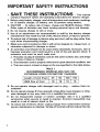
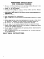
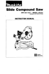
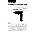
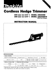
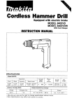
Cordless Trimmer
114''
MODEL 3700D
1/4"
MODEL 3700DW
With Fast Charger
INSTRUCTION MANUAL
SPECIFI CAT I 0N S
Model
*
3700D
Collel L h u c k CdpaclIy
No l o a d speed
Overall l e n g t h
Net weight
114"
8,000 R l m n
165 mm 16 lj2"I
1 0 k g 12 2 I b s l
Battery Cartridge 7000
M o d e l DC7100 Fast charger
~
Charging
Voltage
~
7 2 v
time
_
1 Hr
Input
_
_
_
_
A C only
50 H r
60 H r
_
_
D C
7 2 v
~~
~
Dimensions
IL x W x H i
Net
weight
1 4 5 m m x 80 m m x 61 m m
15 314'' x 3 118'' x 2 ~ 3 / 8 " i
0.7 kg
11 5 lbsl
output
___
Manufacturer reserves the right to change specifications without notice
* Note S p e c i f i c a t i o n s may d i f f e r from country to country
IMPORTANT
SAFETY INSTRUCTIONS
(For All Tools)
WARNING: WHEN USING ELECTRIC TOOLS, BASIC SAFETY PRECAUTIONS SHOULD ALWAYS BE FOLLOWED TO
REDUCE THE RISK OF FIRE, ELECTRIC SHOCK, AND PERSONAL INJURY, INCLUDING THE FOLLOWING:
READ ALL INSTRUCTIONS.
1. KEEP WORK AREA CLEAN. Cluttered areas and benches invite injuries.
2. CONSIDER WORK AREA ENVIRONMENT. Don't use power tools i n damp
or wet locations. Keep work area well lit. Don't expose power tools t o rain.
Don't use tool in presence of flammable liquids or gases.
3. KEEP CHILDREN AWAY. All visitors should be kept away from work area.
Don't let visitors contact tool or extension cord.
4.STORE IDLE TOOLS. When not in use, tools should be stored in dry, and high
or locked-up place - out of reach of children.
5. DON'T FORCE TOOL. It will do the job better and safer at the rate for which
it was intended.
6 . USE RIGHT TOOL. Don't force small tool or attachment t o do the job of a
heavy-duty tool. Don't use tool for purpose not intended.
7.DRESS PROPERLY. Don't wear loose clothing or jewelry. They can be caught
in moving parts. Rubber gloves and n o n s k i d footwear are recommended
when working outdoors. Wear protective hair covering t o contain long hair.
8.USE SAFETY GLASSES. Also use face or dust mask if cutting operation is
dusty.
9.DON'T ABUSE CORD. Never carry tool by cord or yank it t o disconnect from
receptacle. Keep cord from heat, oil, and sharp edges.
IO. SECURE
WORK. Use clamps or a vise t o hold work. It's safer than using
your hand and it frees both hands t o operate tool.
1 1 . DON'T OVERREACH. Keep proper footing and balance at all times.
12. MAINTAIN TOOLS WITH CARE. Keep tools sharp and clean for better and
safer performance. Follow instructions for lubricating and changing accessories. Inspect tool cords periodically and if damaged, have repaired by authorized service facility. Inspect extension cords periodically and replace if
damaged. Keep handles dry, clean, and free from oil and grease.
13. DISCONNECT TOOLS. When not i n use, before servicing, and when changing accessories, such as blades, bits, cutters.
2
14. REMOVE ADJUSTING KEYS AND WRENCHES. Form habit of checking t o
see that keys and adjusting wrenches are removed from tool before turning
it on.
15. AVOID UNINTENTIONAL STARTING. Don‘t carry plugged-in tool with finger
o n switch. Be sure switch is OFF when plugging in.
16. OUTDOOR USE EXTENSION CORDS. When tool is used outdoors, use only
extension cords intended for use outdoors and so marked.
17. STAY ALERT. Watch what you are doing, use common sense. Don’t operate
tool when you are tired.
18. CHECK DAMAGED PARTS. Before further use of the tool, a guard or other
part that is damaged should be carefully checked t o determine that it will
operate properly and perform its intended function. Check for alignment of
moving parts, binding of moving parts, breakage of parts, mounting, and any
other conditions that may affect its operation. A guard or other part that
is damaged should be properly repaired or replaced by an authorized service center unless otherwise indicated elsewhere in this instruction manual.
Have defective switches replaced by authorized service center. Don’t use
tool if switch does not turn it on and off.
19. GUARD AGAINST ELECTRIC SHOCK. Prevent body contact with grounded
surfaces. For example; pipes, radiators, ranges, refrigerator enclosures.
20. REPLACEMENT PARTS. When servicing, use only identical replacement parts.
VOLTAGE WARNING: Before connecting the tool t o a power source (receptacle,
outlet, etc.) be sure the voltage supplied is the same as that specified on the
nameplate of the tool. A power source w i t h voltage greater than that specified
for the tool can result in SERIOUS INJURY t o the user - as well as damage t o
the tool. If in doubt, DO NOT PLUG IN THE TOOL. Using a power source w i t h
voltage less than the nameplate rating is harmful t o the motor.
3
IMPORTANT SAFETY INSTRUCTIONS
I.
SAVE THESE INSTRUCTIONS
- This manual
contains important safety and operating instructions for battery charger.
2. Before using battery charger, read all instructions and cautionary markings
on (1) battery charger, ( 2 ) battery, and (3)product using battery.
3. CAUTION - To reduce risk of injury, charge only MAKITA Battery 7000.
Other types of batteries may burst causing personal injury and damage.
4. Do not expose charger t o rain or snow.
5. Use of an attachment not recommended or sold by the battery charger
manufacturer may result in a risk of fire, electric shock, or injury t o persons.
6. To reduce risk of damage t o electric plug and cord, pull by plug rather than
cord when disconnecting charger.
7. Make sure cord is located so that it will not be stepped on, tripped over, or
otherwise subjected t o damage or stress.
8. A n extension cord should not be used unless absolutely necessary. Use of
improper extension cord could result in a risk of fire and electric shock. If
extension cord must be used, make sure:
a. That pins on plug of extension cord are the same number, size, and shape
as those of plug on charger;
b. That extension cord is properly wired and in good electrical condition; and
c. That wire size is at least as large as the one specified in the table below.
TABLE 1
RECOMMENDED MINIMUM AWG SIZE FOR
EXTENSION CORDS FOR BATTERY CHARGERS
I
Length of Cord (Feet)
1 AWG Size of
Cord
I
I
25
18
I
I
50
18
I
1
100
18
I
I
150
16
9. Do not operate charger w i t h damaged cord or plug - replace them immediately.
IO. Do not operate charger if it has received a sharp blow, been dropped, or otherwise damaged in any way; take it t o a qualified serviceman.
1 1 . Do not disassemble charger or battery cartridge; take it t o a qualified
serviceman when service or repair is required. Incorrect reassembly may
result in a risk of electric shock or fire.
12. To reduce risk of electric shock, unplug charger from outlet before attempting any maintenance or cleaning. Turning off controls will not reduce this risk.
4
ADDITIONAL SAFETY RULES
FOR CHARGER & BATTERY CARTRIDGE
1. Do not charge Battery Cartridge when temperature is BELOW 10°C (5OOF)
or ABOVE 4OoC (104OF).
2. Do not attempt t o use a step-up transformer, an engine generator or DC power
receptacle.
3. Do not ,allow anything t o cover or clog the charger vents.
4. Always cover the battery terminals w i t h the battery cover when the battery
cartridge is not used.
5. A battery short can cause a large current flow, overheating, possible burns
and even a breakdown.
( 11 Do not touch the terminals w i t h any conductive material.
(2)Avoid storing battery cartridge in a container with other metal objects such
as nails, coins, etc.
(3)Do not expose battery cartridge t o water or rain.
6. Do not store the tool and Battery Cartridge in locations where the temperature may reach or exceed 5OoC 1122OF).
7. Do not incinerate the Battery Cartridge even if it is severely damaged or is
completely worn out. The battery cartridge can explode in a fire.
5
ADDITIONAL SAFETY RULES
FOR CORDLESS TRIMMER
1. Be aware that this tool is always in an operating condition, because it does
not have t o be plugged into an electrical outlet.
2. Handle the bits very carefully.
3. Check the bit carefully for cracks or damage before operation. Replace
cracked or damaged bit immediately.
4. Avoid cutting nails. Inspect for and remove all nails from the workpiece before operation.
5. Hold the tool firmly.
6. Keep hands away from rotating parts.
7. Make sure the bit is not contacting the workpiece before the switch is turned
on.
8. Before using the tool on an actual workpiece, let it run for a while. Watch
for vibration or wobbling that could indicate improperly installed bit.
9. Be careful of the bit rotating direction and the feed direction.
10. Do not leave the tool running. Operate the tool only when hand-held.
11. Always switch off and wait for the bit t o come t o a complete stop before
removing the tool from workpiece.
12. Do not touch the bit immediately after operation, it may be extremely hot
and could burn your skin.
13. Keep the bit retracted so as not t o protrude from the tool base except during actual operation.
SAVE THESE INSTRUCTIONS.
6
Installing or removing battery cartridge
0Always switch off the tool before insertion or removal of the battery cartridge.
To remove the battery cartridge, pull out
the s e t plate on the tool and grasp both
sides of the cartridge while withdrawing
it from the barrel.
0
0
To insert the battery cartridge, align the
tongue on the battery cartridge with the
groove in the housing and slip it into
place. Snap the s e t plate back into place.
Be sure t o close the set plate fully before
using the tool.
Do not use force when inserting the battery cartridge.
If the cartridge does not slide in easily, it is not being inserted correctly.
Charging
Plug the fast charger into your power
source. Insert the battery cartridge so that
the plus and minus terminals on the battery cartridge are on the same sides as their
respective markings on the fast charger. Insert the cartridge fully into the port so that
it rests on the charger port floor.
The charging light will come on and charging will begin. If the charging light does not
8
3
come on, press the reset button. If the
charging light goes out within 10 seconds even after pressing the reset button a couple of
times, the battery cartridge i s dead. (CAUTION : Wait for more than 5 seconds after the
charging light goes out to press the reset button again.) Replace it with a new one. When
the ‘charging light goes out after about one hour, you may remove the fully charged
battery cartridge. After charging, unplug the charger from the power source.
CAUTION :
0Your new battery cartridge i s not charged. You will need to charge it before use.
0
0
0
If you try to charge a cartridge from a just-operated tool, sometimes the charging light
will not come on. If this occurs, let the cartridge cool off for a while. Then re-insert
it and try t o charge it once more.
When you charge a new battery cartridge or a battery cartridge which has not been used
for a long period, it may not accept a full charge. This is a normal condition and does
not indicate a problem. You can recharge the battery cartridge fully after discharging
it almost completely a couple of times.
If you wish to charge two battery cartridges, allow 15 minutes between chargings on the
fast charger.
Installing or removing trimmer bit
CAUTION :
Always be sure that the tool i s switched off and the battery cartridge is removed before
installing or removing the bit.
To install the straight bit 6, insert it all the
way into the collet cone and tighten the
collet nut securely with the two wrenches.
To install the straight b i t 3, first insert the
adapter all the way into the collet cone,
then insert the bit all the way into the
adapter. Tighten the collet nut securely
with the two wrenches. To remove the bit,
follow the installation procedure in reverse.
NOTE :
To perform effective operation, the straight bit 3 is recommended only for cutting off or
cutting out the plaster board. The straight bit 6 is used for other operations.
CAUTION :
Do not tighten the collet nut without inserting a bit, or the collet cone will break.
Adjusting depth of cut
Place the tool on a flat surface. Loosen
the clamp screw and move the tool body
until the bit just touches the flat surface.
Tighten the clamp screw slightly. Place the
tool on i t s side and loosen the clamp screw.
Move the tool base until the desired depth
of cut i s obtained. Depth of cut can be
checked with the scale label (2 mm or
about 5/64" per graduation) on the tool.
The tighten the clamp screw securely.
CAUTION :
Since excessive cutting may cause overload of the motor or difficulty in controlling the
tool, the depth of cut should not be more than 5 mm (3/16") a t a pass when cutting
grooves. When you wish to cut grooves more than 5 mm (3/16") deep, make several
passes with progressively deeper b i t settings.
8
Adjusting side base
This tool is equipped with an adjustable
side base. To make the side base flush with
the tool base, loosen the wing bolt and s e t
the tool on a level place. Then tighten the
wing bolt securely.
Switch action
To start the tool, move the slide switch
up. Move it down to stop.
9
Operation
o s e t the tool base on the workpiece to be cut without the bit making any contact. Then
turn the tool on and wait until the b i t attains full speed. Move the tool forward over the
workpiece surface, keeping the tool base flush and advancing smoothly until the cutting
is complete.
0
When doing edge cutting, the workpiece surface should be on the left side of the bit in
the feed direction. (See the figure below.)
(3 Bit revolving
direction
Feed direction
(View from the top of the tool)
I
Correct bit feed direction
NOTE :
Moving the tool forward too fast may cause a poor quality of cut, or damage t o the bit
or motor. Moving the tool forward too slowly may burn and mar the cut. The proper
feed rate will depend on the bit size, the kind of workpiece and depth of cut. Before
beginning the cut on the actual workpiece, it i s advisable to make a sample cut on a
piece of scrap lumber. This will show exactly how the cut will look as well as enable you
to check dimensions.
0
.When using the straight guide or the trimmer guide, be sure to install it on the right side
in the feed direction. This will help to keep it flush with the side of the workpiece.
CAUTION :
I f the tool i s operated continuously until the battery cartridge has discharged, allow the
tool to rest for 15 minutes before proceeding with a fresh battery.
10
Straight guide (optional accessory)
The straight guide is effectively used for
straight cuts when chamfering or grooving.
Attach the guide plate to the straight guide
with the bolt, the wave washer, the flat
washer and the wing nut.
Attach the straight guide with the clamp
screw (A). Loosen the wing nut on the
guide and adjust the distance between the
bit and the straight guide. A t the desired
distance, tighten the wing nut securely.
I
\
Wing nut
When cutting, move the tool with the straight guide flush with the side of the workpiece.
11
Guide base
-
The wide base is effectively used for
straight cuts when chamfering or grooving.
Attach the guide base to the side base with
the wing nuts and bolts.
Adjust the distance between the bit and
the side (A) of guide base by sliding the
guide base. Then tighten the wing nuts
securely. The max. distance is 25 mm ( I " ) .
When chamfering, grasp the tool body with
one hand and press the guide base down
slightly with the other hand as shown in
the figure. The bit should point up so that
you can see it easily. The chamfering angle
may be adjusted by tilting the side base.
The chamfering width may be adjusted by
sliding the guide base.
12
Trimmer guide (Optional accessory)
Trimming, curved cuts in veneers for furniture and the like can be done easily with
the trimmer guide. The guide roller rides
the curve and assures a fine cut.
Install the trimmer guide on the tool base
with the clamp screw (A). Loosen the
clamp screw (B) and adjust the distance
between the bit and the trimmer guide by
turning the adjusting screw (1 mm or about
3/64" per turn). At the desired distance,
tighten the clamp screw (B) to secure the
trimmer guide in place.
=-Guide holder
Clamp screw (A)
Adjusting screw
(1 mm per turn)
Trimmer guide
J
When cutting, move the tool with the guide
roller riding the side of the workpiece.
I kBit
wo
13
Templet guide (Optional accessory)
CAUTION :
For your safety, remove the bit before installing the templet guide.
The templet guide providesa sleeve through
which the bit passes, allowing use of the
trimmer with templet patterns.
To install the templet guide, loosen the
wing bolts and raise the side base. Insert
the templet guide onto the base so that the
notch in the templet guide i s aligned with
the small tab on the base.
Wing bolt
Side base
3
1
Z
1 1
h
Templet guide
Return the side base to i t s original position
and tighten the wing bolts securely.
Secure the templet to the workpiece. Place
the tool on the templet and move the tool
with the templet guide sliding along the
side of the templet.
14
Bt-i
T/e"let
guide
Circle cutting base (Optional accessory)
Various diameter circles can be easily cut with the cordless trimmer by using the optional
circle cutting base.
To attach the circle cutting base, you must
first remove the standard base. This i s done
by removing the base clamp screw and
then removing the standard base from the
trimmer body. The circle cutting base is
then installed, using the same clamp screw.
Be sure to tighten the clamp screw securely.
The circle cutting base is provided with a
“T” shaped guide rod which should be installed by inserting the long part of the rod
through the hole in the base. Pivot the
short part of the rod to position “A” and
tighten the screw.
4 Y
f L
Blt
Thinner end
Thinner end
I
B
I
Screw
To cut a circle, first adjust the bit protrusion for the desired depth of cut, and then
make a pilot hole a t the center point of the
circle. Pivot the guide rod to position ”B”.
When using the straight bit 3, to make the
circle cut-out the thinner end of the rod
should point downward. When using the
straight bit 6, the thicker end of the rod
should point downward. Adjust the distance (L) between the rod and the bit for
the RADIUS of the desired circle you
intend to cut. Then tighten the screw
securely. Insert the end of the rod into the
pilot hole and turn on the trimmer. The
circle can now be cut by pivoting the
trimmer around the pilot hole.
15
NOTE :
The straight bit 3 is recommended to cut plaster board.
MAINTENANCE
CAUTION :
Always be sure that the tool is switched off and the battery cartridge i s removed before
attempting t o perform inspection or maintenance.
To maintain product SAFETY and RELIABILITY, repairs, maintenance or adjustment
should be performed by Makita Authorized or Factory Service Centers, a1way.s using
Makita replacement parts.
16
ACCESSORIES
CAUTION :
These accessories or attachments are recommended for use with your Makita tool specified in this
manual. The use of any other accessories or attachments might present a risk of injury to persons. The
accessories or attachments should be used only in the proper and intended manner.
Fast charger
Model DC7100
Part No. 113086-6
Straight bit 6
Part No. 733195-1
Straight bit 3
Part No. 733197-7
.
Wrench 17
Part NO. 781008-0
*Wrench 1 0
Part No. 781003-0
Charger 1 2 V for car
Model DC7112
Part No. 113109-0
Circle cutting base assembly
Part No. 122318-0
0
Adapter
Part No. 322066-3
Battery cartridge 7000
Part No. 632002-4
Guide base assembly
0
Straight guide assembly
Part No. 122314-8
0
Trimmer guide assembly
Part No. 122315-6
Battery cover
Part No. 414938-7
Battery holster
Holster holds extra battery.
Part No. 823033-3C
1
Templet guide
Part No. 342984-9
Part No. 122313-0
17
Oct -31-'85
EN
6 mm (1/4")
CORDLESS TRIMMER
Model 37000
Note: The switch and other part configurations
may differ from country to country.
18
MODEL 3 7 0 0 0
"5, ,&
Oct -31-'85
DESCRIPTION
O
":'M
$fD
EN
DESCRIPTION
MACHINE
~
1
1
2
3
1
1
4
5
5
6
7
8
9
1
1
2
2
1
10
1
Housing Set (With Item 51
Motor
Switch
Pan Head Screw M4x22 IWith Washer)
Housing Set (With Item 11
Hex Nu1 M 5
Fiat Washer 5
Wing Bolt M5x15
Screw M5x55
Flat Washer 5
08%
Collet Nut
Coilet cone
Spindle
Rubber Pin 4
Rubber Pin 4
Switch Lever
Name Plate
Battery Holder
Note The switch and other part specifications. may differ from country to country
19
P
MAKITA LIMITED ONE YEAR WARRANTY
Warranty Policy
kvery Makita tool is thoroughly inspected and tested before leaving the factory. It is warranted t o
be free of defects from workmanship and materials for the period of ONE YEAR from the date of
original purchase. Should any trouble develop during this one-year period, return the COMPLETE
tool, freight prepaid, to one of Makita’s Factory or Authorized Service Centers. If inspection shows
the trouble is caused by defective workmanship or material, Makita will repair (or at our option,
replace) without charge.
This Warranty does not apply where:
repairs have been made or attempted by others:
repairs are required because of normal wear and tear:
The tool has been abused, misused or improperly maintained ;
alterations have been made t o the tool.
IN NO EVENT SHALL MAKITA BE LIABLE FOR ANY INDIRECT, INCIDENTAL OR CONSEQUENTIAL DAMAGES FROM THE SALE OR USE O F THE PRODUCT. THIS DISCLAIMER
APPLIES BOTH DURING AND AFTER THE TERM O F THIS WARRANTY.
MAKITA DISCLAIMS LIABILITY FOR ANY IMPLIED WARRANTIES, INCLUDING IMPLIED
WARRANTIES O F “MERCHANTABILITY” AND “FITNESS FOR A SPECIFIC PURPOSE,”
AFTER THE ONE-YEAR TERM O F THIS WARRANTY.
Thi\ Warranty g~vesyou specific legal rights. and you may also have other nghts uhich vary trnm
state to stdte Some states do not allow the exclusion or limitation of incidental or consequential
damages, so the above limitation or exclusion may not apply to you. Some states d o not allow
limitation on how long an implied warranty lasts, so the above limitation may not apply to you.
r
Makita Corporation
3-11-8, Sumiyoshi-cho,
Anjo, Aichi 446 Japan
883537E062
PRINTED IN JAPAN
1992 - 7 - N
oct -09 '87 us
114"
TRIMMER
Model 3700B
Note The switch. noise suppressor and other part configurations
may differ from country to country
21
Nov.-25-'85
MODEL 37006
ITEM
NO.
1
2
3
4
5
6
7
9
10
11
12
13
14
15
16
17
in
19
20
21
22
23
24
NO.
USED
1
2
1
2
2
1
1
1
1
2
1
1
2
1
1
1
1
1
1
1
2
1
1
-
DESCRIPTION
Name Plate
Rivet 0 - 5
Motor Rear Housing
Carbon Brush
Brush Holder Cap
Cord
Switch
Cord Guard
Strain Relief
Pan Head Screw M4x18 IWilh Warherl
FIELD ASSEMBLY
Ball Bearing 62 7LB
Hex Bolt M4x70 IWith Washerl
Rubber Pin 4
ln~ulationWasher
ARMATURE ASSEMBLY
IWith Item 13 16 18 & 201
Fan 52
Rubber Pin 6
Ball Bearing 6 0 0 2 L L B
Wave Washer 23
Pan Head Screw M4x18 IWith Warherl
Motor Housing
COllet cone
ITEM
NO.
25
26
27
2n
29
30
31
32
33
34
35
36
37
38
39
40
41
42
43
44
45
46
47
4n
-
NO
USED
1
1
2
1
1
1
1
1
1
1
1
1
1
1
1
4
1
1
1
1
1
1
1
1
-
Note The w i t c h and other part specifications may differ from country to country
22
DESCRlmlON
Collet Nut
Hex Nut M5
Pan Head Screw M4x25 IWtth Washerl
Flat Washer 5
Spring Washer 5
Screw M5x30
Guide Holder
Flat Washer 6
Wave Washer 6
Screw M6x25
Hook
Countersunk Head Screw M4x12 IWith Warherl
Base
Chip Deflector
Base Protector
Countersunk Head Screw M4x10 IWith Warherl
Flat Head Screw M 5
Roller 11
Trimmer Guide
Flat Washer 6
Wave Washer 6
Screw M6x25
Screw M 6
Hex N u t M 1 2
US
MAKITA LIMITED ONE YEAR WARRANTY
Warranty Policy
Every Makita tool is thoroughly inspected and tested before leaving the factory. It is warranted to
be free of defects from workmanship and materials for the period of ONE YEAR from the date of
original purchase. Should any trouble develop during this one-year period, return the COMPLETE
tool, f r e w t prepaid, to one of Makita’s Factory or Authorized Service Centers. If inspection shows
the trouble is caused by defective workmanship or material, Mnkita will repair (or at our option,
replace) without charge.
This Warranty does not apply where:
repairs have been made or attempted by others:
repairs are required because of normal wear and tear:
The tool has been abused, misused or improperly maintained;
alterations have been made t o the tool.
IN NO EVENT SHALL MAKITA BE LIABLE FOR ANY INDIRECT. INCIDENTAL OR CONSEQUENTIAL DAMAGES FROM THE SALE OR USE O F THE PRODUCT. THIS DISCLAIMER
APPLIES BOTH DURING AND AFTER THE TERM O F THIS WARRANTY.
MAKITA DISCLAIMS LIABILITY FOR ANY IMPLIED WARRANTIES, INCLUDING IMPLIED
WARRANTIES OF “MERCHANTABILITY” AND “FITNESS FOR A SPECIFIC PURPOSE,”
AITER THE ONE-YEAR TERM O F THIS WARRANTY.
This Warranty gives you specific legal rights, and you may also have other rights which vary from
state to state. Some states do not allow the exclusion or limitation of incidental or consequential
damages, so the above limitation or exclusion may not apply to you. Some states do not allow
limitation on how long an implied warranty lasts. so the above limitation may not apply to you.
Makita Corporation
3-11-8, Sumiyoshi-cho,
Anjo, Aichi 446 Japan
883014D064
PRINTED IN JAPAN
1991 - 9 - N