1
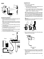
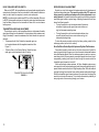
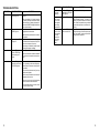
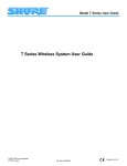
The Computer Headset User Guide SHURE Incorporated Web Address: http://www.shure.com 222 Hartrey Avenue, Evanston, IL 60202–3696, U.S.A. Phone: 847-866–2200 Fax: 847-866-2279 In Europe, Phone: 49-7131-72140 Fax: 49-7131-721414 In Asia, Phone: 852-2893-4290 Fax: 852-2893-4055 Elsewhere, Phone: 847-866–2200 Fax: 847-866-2585 2000, Shure Incorporated 27B8666 (TL) Printed in U.S.A. THANK YOU FOR CHOOSING SHURE Congratulations! You have purchased the finest wireless system in its class. Your Shure wireless system incorporates a clean, lownoise sound that is comparable to other systems costing much more. Built in the tradition of reliability that has made Shure a symbol of quality for more than half a century, this wireless system should provide you with excellent sound for years. To get the most out of your Computer Wireless system, please read this guide before you attempt to use the system. If you have any questions not answered in this booklet, please contact Shure Customer Service at (847) 866–2553, Monday through Friday, from 8:00 am to 4:30 pm, CST. INTRODUCTION The Computer Wireless microphone system brings the freedom of wireless to computer-based voice communication and voice recognition applications. With the system’s headset and transmitter you are free to roam while maintaining a quality voice link with your computer. SYSTEM CONTENTS The Computer Wireless system includes the following: TC1 Transmitter TC3 Standard Receiver PS20 (120 V) or PS20E (230 V) Receiver Power Supply Shure Headset Microphone with Windscreen and Clothing Clip DURACELL 9 V Alkaline Battery Screwdriver (for setting transmitter gain and receiver squelch) Vinyl Transmitter Carrying Bag Rubber Feet (for mounting Receiver) VELCRO Fastening Strips (for alternate mounting of Receiver) 1 Á Á Á ÁÁÁÁÁÁÁÁ Á Á ÁÁ Á ÁÁ ÁÁÁ ÁÁ ÁÁÁÁÁÁÁÁ ÁÁ ÁÁÁÁÁÁÁ ÁÁ Á ÁÁÁÁÁÁÁÁÁ Á Á Á Á Á Á ÁÁÁÁÁÁ ÁÁ ÁÁÁÁÁÁÁ ÁÁÁÁÁ ÁÁÁÁÁÁ Á ÁÁÁÁÁ ÁÁ ÁÁÁÁÁÁ Á ÁÁÁÁÁ ÁÁÁÁÁÁ ÁÁÁÁÁ Á ÁÁÁÁÁ ÁÁÁÁÁÁÁ ÁÁÁÁÁÁ ÁÁÁÁÁ ÁÁÁÁ ÁÁÁÁÁÁ ÁÁÁÁÁ ÁÁÁÁÁÁÁ Á ÁÁ Á Á Á ÁÁÁÁÁÁ ÁÁÁÁÁ ÁÁÁÁÁ ÁÁÁÁÁÁ ÁÁÁÁÁ ÁÁÁÁ ÁÁÁÁÁÁ ÁÁÁÁÁ Á ÁÁ Á ÁÁÁÁÁ ÁÁ Á Á Á ÁÁÁÁÁÁ ÁÁÁÁÁ ÁÁÁÁÁ ÁÁÁÁ ÁÁÁÁÁÁ ÁÁÁÁÁ Á ÁÁ ÁÁ ÁÁÁÁÁ ÁÁ Á Á Á ÁÁÁÁÁ ÁÁ ÁÁÁÁÁ ÁÁÁÁÁÁ ÁÁÁÁÁ Á TC3 RECEIVER COMPONENT FEATURES TC1 TRANSMITTER 1 3 4 5 6 7 2 3 8 2 1 2 9 4 1 5 TC1 TRANSMITTER FIGURE 1 1. Antenna. For best transmission, the antenna must hang vertically; don’t wind or coil it. 2. Battery Compartment. Holds one 9 V alkaline battery. 3. Belt Clip. For attaching the transmitter to your belt or clothing. 4. Power On Indicator. Illuminates when the transmitter is on. 5. Power On/Off Switch. Turns the transmitter on and off. It is recessed to prevent accidental turn off. 6. Audio Mute/On switch. Turns off audio transmission only (when set to “MUTE”) but leaves the transmitter on. 7. Low Battery Indicator. When this red light is glowing, you have one hour or less of useful operating time. 8. Audio Gain Control (Bottom). Controls audio level from headset. Factory preset and normally does not need adjustment. Refer to the section Audio Transmitter Gain Adjustment in this guide. 9. Headset Microphone Input Jack. For connecting the headset microphone to the transmitter. 2 6 7 8 TC3 RECEIVER FIGURE 2 1. Audio Output Jack: For connecting the receiver to the MIC input on your computer or sound card. 2. Power Input Jack: For connecting the receiver to the supplied ac adapter. 3. Telescoping Antenna: Receives signals from the transmitter. Make sure the antenna is fully extended vertically. 4. Power On/Off Indicator (Green): Illuminates when the receiver is plugged into an electrical outlet. 5. RF Signal Indicator (Yellow): Illuminates when rf (radio frequency) signals are received from the transmitter. 6. Audio Peak Indicator (Red): Flickers when the audio signal from the transmitter approaches the overload (clipping) level. 7. Volume Control: Adjusts the volume of the receiver audio output. Does not affect the PEAK indicator. Rotate the volume control clockwise to increase audio output. Rotate it counterclockwise to decrease audio output. 8. Squelch Control (Bottom): Factory preset and normally does not need adjustment. Refer to the section Receiver Squelch Adjustment for more information. 3 SETUP Computer Á Á Á Á ÁÁÁÁ Á Á ÁÁÁ ÁÁÁÁ Á ÁÁ ÁÁÁ ÁÁ Á Headset Transmitter Á ÁÁ ÁÁ Receiver SETUP OVERVIEW FIGURE 3 RECEIVER SETUP (SEE FIGURE 4) 1. Affix the four adhesive rubber feet or the VELCRO fastening strips to the bottom of the receiver and mount it on a flat surface. NOTE: It is best not to place the receiver directly next to or on top of your computer, monitor, or other electronic equipment, as these type of devices can generate rf interference. 2. Plug the supplied ac power adapter (PS20 or PS20E) into a wall socket or other electrical outlet. 3. Connect the ac adapter cable to the receiver DC INPUT connector. The green POWER light on the receiver should come on. 4. Connect the receiver ’s AUDIO OUT to the MIC input on your computer or sound card using the supplied audio cable. 5. Fully extend the telescoping antenna and adjust it so that it is vertical. ÁÁ Á Á Á Á Á Á Á Á ÁÁÁÁÁÁ Á Á ÁÁ Á ÁÁ ÁÁÁÁÁÁ ÁÁÁÁÁ Á Á Á Receiver 90° Computer AUDIO OUT MIC Input TRANSMITTER SETUP FIGURE 4 4 TRANSMITTER SETUP 1. Install the supplied 9 V alkaline battery. a) Turn off the transmitter. b) Press down on the OPEN side of the battery compartment cover, slide it back and flip it open, as shown in Figure 5. c) Insert the supplied 9 V alkaline battery into the battery compartment as shown in Figure 5. Make sure the “+” and “–” battery terminals match the “+” and “–” terminals on the transmitter. NOTE: A Duracell MN1604 battery, like the one supplied, is recommended. A fresh 9 V alkaline battery should typically provide 18 hours of performance time. A fully charged 8.4 V NiCad rechargeable battery should provide 2 hours of performance time. When the red LOW BATTERY light on the transmitter glows, you have 1 hour or less of useful battery life remaining. IMPORTANT: Carbon-zinc and zinc-chloride batteries will not provide adequate power and are not recommended. Á ÁÁÁ Á ÁÁ ÁÁÁÁ ÁÁÁ ÁÁÁÁ ÁÁÁ ÁÁÁ ÁÁÁ ÁÁÁ TC1 BATTERY INSTALLATION FIGURE 5 2. Attach the transmitter belt clip to your belt so that the antenna hangs downward and is not coiled or bundled. ÁÁÁÁÁ Á ÁÁÁÁ ÁÁ Á ÁÁÁÁÁ ÁÁÁ ÁÁÁÁ ÁÁ Á ÁÁ Á Á ÁÁ ÁÁ ÁÁÁ ÁÁÁÁ Á ÁÁ ÁÁ ÁÁÁ ÁÁÁÁ Á ÁÁÁ ÁÁÁÁ Á USING THE BELT CLIP FIGURE 6 3. Slide the transmitter power switch to the ON position. The green POWER ON light on the transmitter should illuminate, indicating that the transmitter is working properly. NOTE: When not in use, turn the transmitter power off to conserve battery power. 5 HEADSET MICROPHONE SETUP 1. The headset features a collapsible boom for shipment and storage. Before wearing the headset, unfold the boom until it snaps and locks into place. Refold for storage or transportation. 2. Place the headset wireframe around the head so that the wireframe and elastic band are horizontal across the back of the head and the ends of the wireframe fit over and in front of the ears (see Figure 7). POSITIONING THE MICROPHONE IMPORTANT: For maximum gain before feedback, position the gooseneck so that the microphone grille (silver side) is within 25 mm (1 inch) of the right corner of the mouth. Do NOT position it directly in front of the mouth (see Figure 9). POSITIONING THE MICROPHONE FIGURE 9 USING THE CLOTHING CLIP The supplied spring-loaded clothing clip secures the microphone cable to the user’s clothing and keeps it from becoming entangled with the user’s movements. WEARING THE HEADSET FIGURE 7 3. If the headset feels loose or uncomfortable, carefully bend the sides of the wireframe to make it tighter or looser (Figure 8A). The angle of the wireframe earpieces may also need adjustment (Figure 8B). CABLE CLOTHING CLIP USING THE CLOTHING CLIP FIGURE 10 A B ADJUSTING THE WIREFRAME FIGURE 8 6 CONNECTING THE HEADSET TO THE TRANSMITTER 1. Insert the headset microphone cable connector into the transmitter input jack. 2. If desired, use the spring-loaded clothing clip to secure any slack from the microphone cable to your clothing. 7 SYSTEM OPERATION ESTABLISHING A WIRELESS LINK When turned on, the transmitter generates a radio frequency (rf) carrier signal that transmits steadily, regardless of whether or not you are using the microphone. When the receiver detects this signal, the yellow rf light on the receiver illuminates, indicating that it recognizes the presence of the transmitter. In the following steps you will use the transmitter’s carrier signal and the receiver’s rf light to test whether or not your setup and environment allows the transmitter and receiver to establish a link. 1. Plug in the receiver so that the green power light illuminates. 2. While wearing the transmitter, stand back from the receiver, but close enough so that you can see the LEDs. 3. Turn the the transmitter power switch on and off. As you do so, the yellow rf light on the receiver should also turn on and off. If the the yellow light does not go on, this indicates that the receiver is not picking up the transmitter’s carrier signal. See the troubleshooting section in this guide. If the yellow light stays on when you turn the transmitter off, this indicates that the receiver is picking up some other rf signal. Computers, monitors, or other electronic equipment can give off rf interference. Try relocating the receiver so that the yellow rf light goes off when the transmitter is off. If the source of interference cannot be eliminated, you may need a wireless system that operates at a different frequency. Contact your Shure dealer. ADJUSTING AUDIO LEVELS Proper adjustment of system audio levels helps deliver a strong audio signal without distortion. Use the following steps: 1. Power on the transmitter and set the transmitter audio mute/on switch to ON. 2. While wearing the headset, talk normally and observe the red peak light on the receiver. It may flicker occasionally. If the peak light remains on as you talk, try positioning the microphone more to the side of your mouth. 3. Activate the computer sound software so that you can view the incoming sound level. Most software has some type of meter or indicator that allows you to do so. You can also use the Windows Sound Recorder applet. 4. Talk at a moderate level as you observe the sound level in the software. Adjust the receiver’s volume control and the software’s audio input control so that the loudest sounds do not exceed the maximum level. Windows Sound Recorder displays a waveform. Make sure the top of the waveform is not being clipped flat. 5. If the software does not respond, check the following: 8 The transmitter should be on and the receiver rf lightshould be illuminated. The audio mute/on switch on the transmitter should be set to the ON position. The receiver volume control should be turned up. The receiver audio output should be plugged into the MIC input on the computer or sound card (NOT the LINE IN input). In the computer audio software, the microphone (MIC) should be selected as the input (or recording) device and the input level control turned up. Make sure the software and sound card are properly installed. The transmitter audio gain control should be fully rotated clockwise (refer to the Transmitter Audio Gain Adjustment section of this guide). TESTING SOUND QUALITY 1. Prepare your computer audio software so that you can record sound from your sound card. 2. Record yourself talking normally for 15 seconds or so. 3. Review the recording and check for the following: A distorted or fuzzy sound probably means that the sound level is too high. Reduce the receiver audio output volume and/or software audio input levels slightly. If your voice sounds weak or distant, increase audio levels. If there is excessive background noise, try positioning the microphone closer to your mouth and adjusting the audio levels down a bit. Be sure that the microphone metal grill is facing towards the mouth. If breath noise or “popping” can be heard, either position the microphone more to the side of the mouth or install the supplied windscreen over the microphone element. 9 USING THE AUDIO MUTE/ON SWITCH When set to MUTE, the transmitter does not transmit audio signals from the microphone to the receiver. Use the mute switch for brief pauses in dictation or when you don’t want the computer to receive voice commands. NOTE: The audio mute/on switch does NOT turn off the transmitter. When set to MUTE, the transmitter continues to transmit a carrier signal and draw power from the battery. Always turn the transmitter off when not in use to conserve battery power. TRANSMITTER AUDIO GAIN ADJUSTMENT The audio gain control on the transmitter allows you to decrease the audio signal level coming from the headset. It is factory preset at the maximum setting (full clockwise). In most circumstances, this control should not require adjustment. To decrease Audio Gain: Rotate the transmitter gain control counterclockwise with the supplied screwdriver. See Figure 11. To Return Gain to the Factory Setting: Rotate the transmitter gain control clockwise as far as it will go. ÁÁÁÁÁÁÁÁ Á Á ÁÁ Á Á Á Á ÁÁ Á ÁÁÁÁÁÁÁÁ ÁÁ Á Á R TRANSMITTER GAIN ADJUSTMENT FIGURE 11 10 RECEIVER SQUELCH ADJUSTMENT Squelch is a circuit in the receiver that mutes audio output in the absence of the desired transmitter signal. The squelch control on the TC3 receiver is factory preset for optimum performance. No further adjustment is normally required. It is possible to adjust the squelch control setting to emphasize either signal quality or system range. Adjusting the squelch control produces the following results: Turning the squelch control clockwise causes the receiver to demand a higher quality signal (less noise before muting), but decreases operating range. Turning the squelch control counterclockwise allows a lower quality signal through (more noise before muting), but increases operating range. To return the receiver squelch control to the factory setting, rotate it to the mid-range position (so the slot is vertical). How the Shure Noise Squelch Improves System Performance Conventional squelch circuits work on the basis of received rf (radio frequency) signal strength. However, such circuits cannot discriminate between noise and desired signals. When the wireless system is used in an environment where lots of rf noise is present, conventional squelch circuits can “open” unexpectedly, sending loud bursts of noise through the receiver when the transmitter signal is weak or turned off. Unlike conventional wireless systems, all Shure Headset systems use a noise squelch circuit that analyzes signal quality along with signal strength. A special detector monitors the level of high frequency noise. When the transmitter signal is strong, the noise level is low and the receiver sends audio through. When the transmitter signal is weak or absent, the noise level is high and the squelch circuit mutes the receiver. This virtually eliminates the possibility of annoying bursts of noise coming through your receiver. 11 TROUBLESHOOTING PROBLEM No sound. No sound. No sound. INDICATOR STATUS SOLUTION Green transmitter POWER light off. Slide transmitter power switch to ON position. Make sure battery is inserted properly (+/– battery terminals must match transmitter terminals). If battery is properly inserted and POWER ON light still does not glow, replace battery. Green transmitter POWER light on. Make sure headset microphone is plugged into the transmitter. Green receiver POWER light off. Slide transmitter audio mute/on switch to ON position. Make sure ac adapter is securely plugged into electrical outlet and into dc input connector on rear panel of receiver. PROBLEM INDICATOR STATUS Distortion level increases gradually. Receiver RF light on. Transmitter LOW BATTERY light on. Replace transmitter battery. SOLUTION Bursts of noise, distortion, or other radio signals interrupting performance. Receiver RF light on. Identify potential sources of interference (other wireless systems, TV or radio, CB radios, etc.) and turn them off or remove them. If this is not possible, use a wireless system that operates on a different frequency. Momentary loss of sound as transmitter is moved around the area where system is used. Receiver RF light off when sound is lost. Reposition receiver and perform walkthrough test again. If audio dropouts persist, mark “dead” spots and avoid them during wireless operation. Make sure ac electrical outlet works and supplies proper voltage. No sound. Receiver RF light on. Receiver PEAK light flickers during loud sounds. Turn up receiver volume control. Make sure the cable connection between the receiver and computer sound port is good. No sound. Receiver RF light off. Transmitter and receiver POWER lights on. Make sure the transmitter and the receiver are operating on the same frequency. Extend receiver antenna vertically as far as possible. Move receiver antennas away from any nearby metal objects. Remove any obstructions from between transmitter and receiver. Make sure you can see receiver antenna from the location of the transmitter. Move transmitter closer to receiver; it may be outside system range. 12 13 TECHNICAL SPECIFICATIONS RF Carrier Frequencies Frequency (MHz) Model Number TCHS-V . . . . . . . . . . . . . . . . . . . . . . . . . . . . . . . . . . . 169.445 TCHS-W . . . . . . . . . . . . . . . . . . . . . . . . . . . . . . . . . . 171.845 TCHS-AC . . . . . . . . . . . . . . . . . . . . . . . . . . . . . . . . . 170.245 TCHS-CA/ETCHS-CA . . . . . . . . . . . . . . . . . . . . . . . 176.200 TCHS-CC/ETCHS-CC . . . . . . . . . . . . . . . . . . . . . . . 177.600 TCHS-CE/ETCHS-CE . . . . . . . . . . . . . . . . . . . . . . . 182.200 TCHS-CF/ETCHS-CF . . . . . . . . . . . . . . . . . . . . . . . 183.600 TCHS-CG/ETCHS-CG . . . . . . . . . . . . . . . . . . . . . . 186.200 TCHS-CL/ETCHS-CL . . . . . . . . . . . . . . . . . . . . . . . 192.200 TCHS-CQ/ETCHS-CQ . . . . . . . . . . . . . . . . . . . . . . 202.200 TCHS-CV/ETCHS-CV . . . . . . . . . . . . . . . . . . . . . . . 208.200 Operating Range 100 m (approximately 300 ft) under optimal conditions Operating Temperature Range –20° to 50° C (–4° to 122° F) NOTE: Battery characteristics may limit this range Dimensions TC1 Transmitter: 64 mm H x 106 mm W x 24 mm D (2.53 x 4.19 x 0.97 in.) TC3 Standard Receiver: 35 mm H x 152 mm W x 98 mm D (1.19 x 6 x 3.88 in.) Cable (Receiver to Computer) 6 ft, 1/4 in. mono to 1/8 in. stereo Tip: audio Sleeve: shield Ring (1/8 in. plug): not connected Net Weight TC1 Transmitter: 96.4 g (3.4 oz) TC3 Receiver: 192 g (6.8 oz) Power Requirements TC1 Transmitter: 9 V alkaline battery (DURACELL MN1604 recommended, 1 included); 8.4 V NiCad battery optional Battery Life: 18 hours typical with fully charged 9 V alkaline battery, 2 hours typical with fully charged NiCad battery TC3 Receiver: 12–18 Vdc nominal, 85 mA Transmitter Current Drain TC1 Transmitter: 30 mA, typical Certifications TC1 Transmitter: Type Accepted under FCC Parts 74 and 90. Certified by IC in Canada under TRC-78. TC3 Receiver: Approved under the Notification provision of FCC Part 15. Certified by IC in Canada under TRC-78. MICROPHONE SPECIFICATIONS Frequency Response (at 8 mm [0.31 in.]) 50 to 15,000 Hz Polar Pattern Noise-cancelling, cardioid (unidirectional) response—uniform with frequency, symmetrical about axis Output Level (close–talked at 1,000 Hz) Open Circuit Voltage: –47.0 dBV (4.5 mV) at 114 SPL (0 dB = 1 V/100 µbar) Cable (Headset) Attached 1.22 m (4 ft), single-conductor, small-diameter, shielded, rubber-jacketed with right-angle 1/4 in. phone plug Net Weight 60.4 g (2.12 oz) including connector FURNISHED ACCESSORIES Screwdriver . . . . . . . . . . . . . . . . . . . . . . . . . . . . . . . . . . . . . . . . . . . . . . . . . . 65A1659 Receiver AC Adapter . . . . . . . . . . . . . . . . . . . . . . PS20 (120 V) or PS20E (230 V) Vinyl Transmitter Bag . . . . . . . . . . . . . . . . . . . . . . . . . . . . . . . . . . . . . . . . . . . . 26A13 Audio Connector Cable, 6 ft, 1/4 in. to 1/8 in. Plugs . . . . . . . . . . . . . . . . . . . . . C124 OPTIONAL ACCESSORIES Neoprene Bodypack Belt Pouch (for TC1 Transmitter) . . . . . . . . . . . . . . . WA570 REPLACEMENT PARTS Black Microphone Windscreens (2) and Clothing Clip . . . . . . . . . . . . . RK318WS Belt Clip . . . . . . . . . . . . . . . . . . . . . . . . . . . . . . . . . . . . . . . . . . . . . . . . . . . . . . 90B4392 SERVICE For additional microphone service or parts information, please contact Shure’s Service department at 1–800–516–2525. Outside the United States, please contact your Authorized Shure Service Center. LIMITED ONE-YEAR WARRANTY Shure Incorporated (“Shure”) hereby warrants that this product will be free from defects in materials and workmanship for a period of one year from the date of purchase for all cartridge and housing assembly parts and for a period of one year from the date of purchase for all transmitter parts. At its option Shure will repair or replace the defective product and promptly return it to you, or refund the purchase price. You should retain proof of purchase to validate the purchase date and return it with any warranty claim. If you believe this product is defective within the warranty period, carefully repack the unit, insure it, and return it postage prepaid to: Shure Incorporated Attention: Service Department 222 Hartrey Avenue Evanston, Illinois 60202-3696 U.S.A. Outside the United States, return the product to your dealer or Authorized Service Center. This warranty does not apply in cases of abuse or misuse of the product, use contrary to Shure’s instruction, or unauthorized repair. All implied WARRANTIES OF MERCHANTABILITY or FITNESS FOR A PARTICULAR PURPOSE are hereby disclaimed and Shure hereby disclaims liability for incidental, special, or consequential damages resulting from the use or unavailability of this product. Some states do not allow limitations on how long an implied warranty lasts, or the exclusion or limitation of incidental or consequential damages, so the above limitation may not apply to you. This warranty gives you specific legal rights, and you may have other rights which vary from state to state. THIS WARRANTY SUPERSEDES ALL WARRANTIES THAT ARE INCLUDED WITH THIS PRODUCT 14 15 Declaration of Conformity We of Shure Incorporated 222 Hartrey Ave. Evanston IL 60202–3696 U.S.A. 847–866–2200 declare under our sole responsibility that the following product, Model: TC3 Name: TC3 Receiver was tested and found to comply with Part 15 of the FCC rules. Operation is subject to the following two conditions: (1) this device may not cause harmful interference, and (2) this device must accept any interference received, including interference that may cause undesired operation. Testing was completed by the following NVLAP or A2LA accredited laboratory: BZT privat CETECOM GmbH 66117 Sarbruken Unterturkheimer StrBe 6–10 Deutschland telephone +49 681 598 – 9000 fax +49 681 598 – 9075 Shure Inc., Manufacturer. Signed: Date: June 15, 1999 Name, Title: Craig Kozokar, Senior Quality Engineer Additional Information for this Shure Wireless System This Shure wireless transmitter is accepted under FCC Part 74 and/or Part 90. IMPORTANT: Licensing of Shure wireless microphone equipment is the user’s responsibility, and licensability depends on the user’s classification and application, and on the selected frequency. Shure urges the user to consult the appropriate telecommunications authority before choosing and ordering frequencies. Changes or modifications not expressly approved by Shure Inc. could void your authority to operate this equipment. The information on this page supersedes the corresponding information in your Shure user’s guide. 16