1
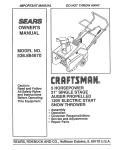
IMPORTANT MANUAL
Do Not Throw Away
S _A/RS
Operator's
Manual
Model No.
358.797450
CUSTOMER
ASSISTANCE
1-800-235-5878
Always
Wear Eye Protection
FTSMRN°
1.3 cu. in./21cc 2-CYCLE
Gear Driven
GASOLINE EDGER
WARNING:
READ THE OPERATOR'S
MANUAL AND FOLLOW
ALL WARNINGS AND
SAFETY INSTRUCTIONS.
FAILURE TO DO SO CAN
RESULT IN SERIOUS
INJURY.
i
Sears,
Roebuck
5._'_36_-1-o311
o/gs
• Assembly
• Operation
• Customer Responsibilities
• Service and Adjustments
• Repair Parts
and Co., Hoffman
Estates,
IL 60179
U.S.A.
SAFETY RULES
ALWAYS
DISCONNECT SPARK PLUG WIRE AND PLACE WIRE WHERE IT CANNOT CONTACT
WARNING:
SPARK PLUG TO PREVENT ACCIDENTAL STARTING WHEN SETTING UP,TRANSPORTING,
ADJUSTING OR MAKING REPAIRS EXCEPT CARBURETOR ADJUSTMENTS.
OPERATOR
SAFETY
• Always wear eye protection when operating, servicing, or performing maintenance on your unit. See
"Accessories."
• Always wear heavy, long pants, long sleeves, boots,
and gloves. Do not go barefoot or wear short pants,
sort sleeves, or sandals. Loose clothing, jewelry, or
clothing with loosely hanging straps, ties, tassels, etc.,
can be caught in moving parts. Secure hair so it is
above shoulder length. Being fully covered will help
protect you from pieces of toxic plants such as poison
ivythrown by the blade, which could be more of a hazard than touching the plant itself.
• Do not operate unitwhen you are tired, ill, or under the
influenceof alcohol, drugs, or medication.
• Wear hearing protection when using this unit.
• Never start or run the unit inside a closed room or
building. Breathing exhaust fumes can kill.
• Keep handles free of oil and fuel.
° Always use the handle.
EDGING SAFETY
- Inspect the area to be edged before each use.
Remove objects (rocks, broken glass, nails, wire,
string, etc.) which can be thrown by the blade or can
wrap around the shaft.
• Keep others including children, animals, bystanders,
and helpers at least 50 feet (15 meters) away.Stop the
unit immediately if you are approached.
• Hold the unit firmly with both hands.
• Keep firm footing and balance. Do not over-reach.
• Always keep the wheels in contact with the ground.
• Keep all parts of your body away from the blade and
muffler.
• Always push the unit slowly over the ground. Stay alert
for uneven sidewalks, holes in the terrain, large roots,
etc.
• Use onlyfor jobs explained in this manual.
UNIT MAINTENANCE
SAFETY
• Inspectentire unitbefore each use. Replace damaged
parts. Check for fuel leaks. Make sure all fasteners are
in place and securely fastened.
• Maintain the unit according to recommended procedures.
• Throw away blades that are bent, warped, cracked,
broken, or damaged in any other way+Replace parts
that are cracked, chipped, or damaged before using
the unit.
° Use only SEARS replacement blades. Never use wire,
rope, string etc.
• Use only recommended SEARS parts and accessories.
• Disconnect the spark plug before performingmaintenance (except for carburetor adjustments).
• Remove the blade before making carburetor adjustments. Hold the unit by hand. Do not make carburetor
adjustments from the blade side of the unit.
• Keep others away when making carburetor adjustments.
• Never start the unit with the gear box removed. The
clutch can fly off and cause serious injury.
° Have all maintenance and service not explained in
this manual performed by your Sears Service Center.
FUEL SAFETY
° Mix and pour fuel outdoors and where there are no
sparks or flames.
• Use a container approved for fuel.
* Do not smoke or allow smoking near fuel orthe unit or
while using the unit.
• Wipe up all fuel spills before starting unit.
* Move at least 10 feet (3 meters) away from fueling site
before starting unit.
• Stop engine and allow unit to cool before removing the
fuel cap.
TRANSPORTING
AND STORAGE
• Stop the unit before leaving the work area.
•Ailow the unit to cool, run fue! out of the fuel tank, and
secure the unit before storing or transporting it in a
vehicle.
* Before storing the unit, use up fuel left in the carburetor by starting the unit and letting it run until it stops.
Always allow the unit to coo! before storage+
• Store unit and fuel in an area where fuel vapors cannot reach sparks or open flames from water heaters,
electric motors or switches, furnaces, etc.
* Store unit so the blade cannot accidentally cause
injury.
• Store unit out of reach of children.
SAFETY NOTICE
I Exposure to vibrationsthrough prolonged use of gasoline powered hand tools could cause blood vessel or nerve damage in the l
Ifingers, hand, and joints of people prone to circulationdisordersor abnormal swellings. Prolonged use in cold weather has been I
Ilinked to blood vessel damage in otherwise healthy people, tfsymptoms occur such as numbness, pain, loss of strength,change !
tin skin color or texture, or loss of feeling in the fingers, hands or joints, discontinue the use of this tool and seek medical atten-}
Ition. An anti-vibration system does not guarantee the avoidance of these problems.Users who operate power tools on a cent!n- I
lual and reguiar basis must monitor closely their physical conditionand the condition of this unit.
I
_C_
LOOK
FOR - THIS
SYMBOL
IT MEANS
ATTENTION!.t!
TO
POINT
BECOME
OUT
IMPORTANT
SAFETY IS PRECAUTIONS.
ALERT!!!
YOUR SAFETY
INVOLVED.
-2-
t
1
SAFETY RULES
DANGER
THIS POWER TOOL CAN BE DANGEROUS! THIS UNIT CAN CAUSE SERIOUS INJURY INCLUDING AMPUTATION OR BLINDNESS TO THE OPERATOR AND OTHERS. THE WARNINGS AND
SAFETY INSTRUCTIONS IN THIS MANUAL MUST BE FOLLOWED TO PROVIDE REASONABLE
SAFETY AND EFFICIENCY IN USING THIS UNIT. THE OPERATOR IS RESPONSIBLE FOR FOLLOWING THE WARNINGS AND iNSTRUCTIONS IN THIS MANUAL AND ON THE UNIT. READ THE
ENTIRE OPERATOR'S MANUAL BEFORE ASSEMBLING AND USING THIS UNIT! RESTRICT THE
USE OF THIS POWER UNIT TO PERSONS WHO READ, UNDERSTAND, AND FOLL OW THE WARNINGS AND INSTRUCTIONS IN THIS MANUAL AND ON THE UNIT. NEVER ALLOW CHILDREN TO
USE THIS UNIT.
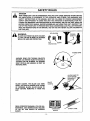
WARNING:
LEG GUARDS
'__TH
ROV'¢N
BLADE CAN THROW OBJECTS VIOLENTLY. YOU CAN BE BLINDED OR INJURED.
WEAR EYE AND LEG PROTECTION
HAZARDZONE
J
HAZARD ZONE FOR THROWN OBJECTS.
EDGER CAN THROW OBJECTS VIOLENTLY.
OTHERS CAN BE BLINDED OR INJURED.
KEEP PEOPLE AND ANIMALS 50 FEET (15
METERS) AWAY.
ALLOW BLADE TO
STOP BEFORE
FROM THE
BLADE
BLADE COASTS. THE BLADE CAN SERIOUSLY CUT YOU OR OTHERS. STAY CLEAR
OF SPINNING BLADE. ALLOW BLADE TO
STOP BEFORE REMOVING IT FROM THE
CUT.
CUT
COAST_
__
READ OPERATOR'S MANUAL FOLLOW ALL
WARNINGS AND INSTRUCTIONS. FAILURE
TO DO SO CAN RESULT IN SERIOUS
INJURY.
OPERATOR'S
MANUAL
-3-
REMOVING IT
CONGRATULATIONS
on yourpurchaseof a Sears
Craftsman
Gasoline
Edger.
It hasbeendesigned,
engineeredandmanufactured
togiveyouthebestpossible
dependability
andperformance.
Shouldyouexperience
anyproblems
youcannoteasily
remedy,pleasecontactyour nearestSearsService
Center/Department.
Searshas competent,
well trained
technicians
and the proper tools to service or repair this
unit.
Please read and retain this manual. The instructionswill
enable you to assembleand maintain your unit properly.
Always observe the "SAFETY RULES."
r
MODEL NUMBER:
DATE OF PURCHASE:
THE MODEL AND SERIAL NUMBER WILL BE FOUND
ON THE PRODUCT
YOU SHOULD RECORD BOTH SERIAL NUMBER AND
DATE OF PURCHASE AND KEEP IN A SAFE PLACE
FOR FUTURE REFERENCE.
AGREEMENT
A Sears Maintenance Agreement is available on this product. Contact your nearest Sears Store for details.
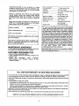
CUSTOMER
ENGINE: ................................ 2-cycle Air Cooled
FUEL MiX: ............................. 40:1 (3.2oz oil per gallon gas)
IGNITION: ............................. Solid State
(Air gap .010"-.014")
IGNITION TIMING: ................ Non-Adjustable, Fixed
SPARK PLUG TYPE: ............ Champion RCJ-SY
SPARK PLUG GAP: ............... 025" (.63ram)
MUFFLER: ............................ Temperature Limiting (and
spark arresting)
ENGINE RPM: ...................... 9,200 RPM Maximum
For users on U.S. Forest Land and in some states
including California (Public Resources Codes 4442 and
4443), Idaho, Main, Minnesota, New Jersey, Oregon,
and Washington: Certain internat combustion engines
operated on forest, brush, and/or grass-covered lands
in the above areas are required to be equipped with a
spark arrestor, maintained in effective working order, or
the engine must be constructed, equipped, and maintained for the prevention of fire. Check with your state or
local authorities for regulations pertaining to these
requirements. Failure to follow these requirements is a
violation of the law. This unit is not factory-equipped
with a spark arrestor; however, a spark arrestor is available as an optional part. If a spark arrestor is required
in your area, contact
your SEARS Service
Center/Department for the correct kit.
358.797450
DATE CODE/SERIAL NO.
MAINTENANCE
DISPLACEMENT: ................. t .3 Cubic Inches (21cc)
MANUFACTURED
UNDER ONE OR MORE OF THE FOLLOWING U.S. PATENTS:
4,904,827: 4.904,827;4,846,123: 4,463,544; 4.451.983; 4.364,435; 4.2B_,675; Re,32,266
OTHER U.S.AND FOREIGN PATENTS PENDING.
RESPONSIBILITIES
• Read and observe the safety rules.
• Follow a reguiar schedule in maintaining, caring for, and
using your unit.
• Follow
the
instructions
under
"Customer
Responsibilities" and "Storage" sections of this
Operator's Manual.
FULL ONE YEAR WARRANTY
ON CRAFTSMAN
GAS EDGER
For one year from the date of purchase, when this Craftsman Edger is maintained, lubricated, and tuned up according
to the instructions in the owner's manual, Sears will repair, free of charge, any defect in material or workmanship.
If thisCRAFTSMAN edger is used for commercial or rental purposes, this warranty appliesfor only 90 days from the date
of purchase.
THIS WARRANTY DOES NOT COVER:
Expandable items which become worn during normal use, such as rotary and/or edger blades, blade guides, blade
adapters, air cleaners, spark plugs, tire chains and shear pins.
Repairs necessary because of operator abuse or negligence, including bent crank shafts and the failure to maintain
the equipment accordingto the instructions contained in the owner's manual.
WARRANTY SERVICE tS AVAILABLE BY RETURNING THE CRAFTSMAN EDGER TO THE NEAREST SEARS SERVICED CENTER IN THE UNITED STATES.
This warranty gives youspecific legal fights, and you may also have other rightswhich vary from state to state.
MADE IN U.S.A. Sold by SEARS, ROEBUCK AND CO., DI 8t7WA, HOFFMAN ESTATES, IL 60179
-4-
TABLE OF CONTENTS
..
iiiiiii
iiiiiiiiiii1[
iiiii
i
iiiiiiiiiiiiiii
i
i
iii
iiiiiiiii
iiiiii
iiiiiiii iii
Safety Rules ................................ ,......,, ................... i__.2
Customer Responsibilities ............................................. 14
Product Specification ...................................................... 4
Service and Adjustments .............................................. 16
Warranty .......................................................................... 4
Storage .......................................................................... 19
Accessories ..................................................................... 5
Trouble Shooting ........................................................... 20
Assembty......................................................................... 7
Repair Parts .................................................................. 21
Operation. ...................... :.;::::,. .......... ;""1..:.':.;":" .............8 .....Repair Parts Order!ng/Service .......... ......... Back Cover
INDEX
,,,
,,,,,,,,
..................................................
,,,,,,,,
A
Accessories ..................................................................... 5
Air Filter ......................................................................... t4
Assembly ......................................................................... 7
B
Blade ............................................................ ................. 15
C
Carburetor Adjustments ................................................ 16
Controls ........................................................................... 9
Customer Responsibilities ............................................. 14
E
Edging ........................................................................... 12
Engine
FueVOtl ................................................................... 10
Spark Plug .............................................................. 15
Starting ................................................................... tl
Storage ................................................................... 19
F
Fuel Filter ...................................................................... 15
Fueling .......................................................................... 10
H
Canon Contents .............................................................. 6
How To Use Your Edger .................................................. 9
,
HIII I
K
Know Your Edger ............................................................. 8
M
Maintenance Schedule ................................................. 14
Model Number ................................................................. 4
O
Operation ........................................................................ 8
Ordering Repair Parts .................................... Back Cover
R
Repair Paris .................................................................. 21
S
Service and Adjustments .............................................. 16
Spark Plug ..'.................................................................. 15
Specifications .................................................................. 4
Starter Rope.................................................................. 17
Starting .......................................................................... 11
Storage .......................................................................... 19
T
Trouble Shooting ........................................................... 20
W
Warranty .......................................................................... 4
.....................................
,
,,,,,,,,,,,, i
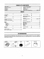
ACCESSORIES
....,,,
i,ii
i
IIHI
, ......
,[]
These accessories and attachments were available when the unit was originally purchased. They are also available at
most Sears retail outlets and service centers. Most Sears stores can order these items for you when you provide the
model number of your unit.
SAFETY'
GOGGLES
2-CYCLE
ENGINE
OIL
FUEL
CAP
BLADE
3.2OZ,
8 OZ.
16OZ.
-5-
GAS CAN
H.= .H=
..=..H=
=
,,,,,,,,,,,,,,,,,,,,,,,,,,
,,=
.H....
=HIH=
"""=
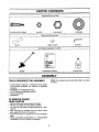
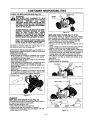
CARTON CONTENTS
iiiiiiiiiilu
iiiiiiiui
i
ii
IIIIIIIIIIIIJJlIIIHI
I
i
i
i
II
i
ii
iii
Hardware shown full size
(2) SHOULDER
SCREWS
(2) NUTS
(1) BLADE
NUT
(t) WASHER
Parts not shown full size
BLADE
CABLECLAMP
HEX KEY
Parts packed separately in carton
---!_
,!
• I
p-_
I
OPERATOR'SMANUAL
EDGER
iiiii
iii ii
i
=
i
FUEL]OILMIX
iiiii
ii
iiii
iiii
ASSEMBLY
NOTE: It is normal to hear the fuel filter rattle in an empty
fuel tank.
TOOLS REQUIRED FOR ASSEMBLY
• Torque Wrench (optional) - Reference torque values
are provided throughout this manual for tightening
hardware.
• 3/8"Wrench (or Adjustable wrench)
• 11/16"Wrench (or Adjustable wrench)
• Hex Key (provided)
• Screwdriver
TO REMOVE EDGER
FROM CARTON
• Remove looseparts bag included with Edger
• Remove youredger from the packing material.
• You may use the opened packing material as a work
surface.
• After removing the contents from the carton, check
parts against the Carton Contents list,
• Examine the parts for damage, Do not use damaged
parts.
• Notify CUSTOMER ASSISTANCE at 1_800-235-5878
immediately if a part is missing or damaged.
-6-
ASSEMBLY
_1_
J
ANGER:
DO NOT START THE ENGINE WITHOUT
THE GUARD AND BLADE COMPLETELY
ASSEMBLED. OTHERWISE, THE CLUTCH
CAN COME OFF AND SERIOUS INJURY
CAN RESULT.
ALWAYS WEAR GLOVES WHEN HANDLINGTHE BLADE. THE BLADE CAN BE
SHARP ENOUGH TO CUT YOU EVEN
THOUGHITISTOO
DULLTO CUTWOOD.
Figure2
IF UNIT IS RECEIVED ASSEMBLED,
REVIEW ALL STEPS IN THIS SECTION TO
BE SURE ASSEMBLY IS CORRECT AND IS
ADJUSTED FOR THE OPERATOR.
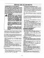
BLADE ASSEMBLY (Fig, 3)
WARNING:
WEAR PROTECTIVE GLOVES WHEN
HANDLING OR PERFORMING MAINTENANCE ON THE BLADE TO AVOID
INJURY.
HOW TO ASSEMBLE YOUR EDGER
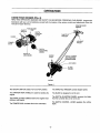
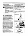
TUBE ASSEMBLY (Fig. 1 & 2)
• Loosen the two upper screws in the housing clamp.
Then, remove and discard the shipping plug. Figure 1.
• Insert the lower tube into the housing, clamp with the
groove in the tube aligned with the ridge in the housing.
° Firmly push lowertube intothe housing until the bold line
on the decal is not visible (about 2-1/4").
° Securely tightenall four screws in the housingclamp.
NOTE: In performing the next step, be sure the handle is
alignedwith the label on the top and the throttletriggeron
the operator'sright hand side. Figure 1 inset. The starter
rope and throttle cable mustnot wrap around the tube.
• Assemblethe handle tube to the lowertube (it wilt be
necessary to pull some of the starter rope out of the
housing).Alignthe screwholes.
• Insertthe two screws through the alignedholesoThread
nut ontoeach screw and tightensecurely.Figure 1.
NOTE: In performingthe nextstep, be surethe starter rope
is not caught under the cableclamp.Thestarter rope must
hang freely to operateproperly.
install the cable in the cable ciamplocating groove. Fig2.
• Alignthe cable clamp between screws. Installthe cable
clamp around the tube and throttlecab_e.Figure2.
LABEL
• Place the blade on the blade shaft; match theflat area of
the blade opening with theflat side of the shaft, Figure 3.
• Installwasher, making sure to installthe cupped side facing • e blade.
• Install nut counterclockwise on the blade shaft.
• Bindthe blade by inserting a screwdriver into the hole in
the gearbox; then, tighten the nut with a wrench until the
washer is flattened firmly against the blade.
NOTE: To removethe blade, bind the blade by inserting a
screwdriver intothe hole in the gearbox; then, remove the
nut, washer, and blade from the blade shaft.
NUT C
FLAT SIDES
HANDLE TUBE
THROTTLE,
m,,._ = _"
Figure 3
TRtGG_
TWO
TLOWER
UBE
UPPER
BOLD LINE
ON DECAL
NUTS
HOUSING
CLAMP
RED
SHIPPING PLUG
(Remove and Discard]
Figure 1
-7-
OPERATION
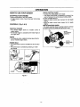
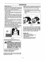
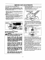
KNOWYOUR
EDGER (Fig. 4)
READ THIS OPERATOR'S MANUAL AND SAFETY RULES BEFORE OPERATING YOUR EDGER. Compare the
illustrationswith your unit to familiarize yourself with the locationof the various controls and adjustmentS.Save this
manual for future reference.
STARTERROPE
HANDLE
FUEL/OIL
MIX
ON/OFF
SWITCH
CAP
_
DEPTH
CONTROL
THROTTLE
TRIGGER
LEVER
CHOKE
AIR INLET
HOLES
PRIMER
BULB
DEPTH
WHEEL
MUFFLER
AND GUARD
SPARK
PLUG
SERIAL NUMBER
AND STARTING
INSTRUCTIONS
FILTER
BLADE
GUARD
BLADE
Figure 4
The ON/OFF SWITCH selects"On" and "Off" position.
The THROTTLE TRIGGER controlsengine speed.
The STARTER ROPE HANDLE is used for starting the
engine.
The BLADE is designed to cut the sod.
The DEPTH ADJUSTING WHEEL removes the blade
from the cut when the unit is not in use.
The CHOKE provides additionalfuel to the engine when
stating a cold engine,
The DEPTH CONTROL LEVER regulates the cutting
depth.
The PRIMER BULB cimulates fuel to the carburetor.
-8-
OPERATION
HOW TO USE YOUR EDGER
STOPPING YOUR ENGINE
• Move on/off switch to the "Off" position.
• If engine does not stop, move choke lever to fult choke
position.
CONTROLS
(Fig.
5 & 6)
THROTTLE TRIGGER
• The throttle tdgger allows for variable contmt of
engine speed.
, The throttle trigger is actuated by the index finger on
your right hand.
DEPTH CONTROL LEVER
• Controls the cutting depth of the blade.
• The Depth control lever is operated by moving it forward or backwardto set the desired cutting depth.
TO SET EDGING DEPTH:
° Move the depth control lever rearward for half depth
edging.
• Move the depth control lever forward for full depth
edging.
DEPTH ADJUSTING WHEEL
° The depth adjusting wheel is spring loaded to remove
the blade from the cut when the unit is not in use.
WHEEL
ADJUSTMENT
CONTROL
CHOKE
• The choke is set by rotating the choke lever fully for
cold or refueted engine starts.
DEPTH
PRIMER BULB
• The primer bulb is used to circulate fuel to the carburetor.
• The primer bulb is activated by pressing on it with
your thumb.
WHEEL
Figure 6
BULB
CHOKE
Figure 5
-9-
OPERATION
BEFORE
STARTING
ENGINE:
CRAFTSMAN 40:1 2-cycle engine oil (AIR-COOLED) is
specially blended with fuel stabilizers. If you do not use
this Sears oil, you can add a fuel stabilizer (such as
CRAFTSMAN No. 33500) to your fuel tank.
WARNING:
BE SURE TO READ THE FUEL HANDLING
INFORMATION IN THE SAFETY RULES
SECTION ON PAGE 2 OF THIS MANUAL
BEFORE YOU BEGIN.
40:1 2-CYCLE AIR-COOLED
CRAFTSMAN 40:1 2-cycle engine oil (AIR-COOLED) is
strongly recommended.This oil is specially blended with
fuel stabilizers for increased fuel stability (extends fuel
life up to 5 times longer) and reduced smoke.
IF YOU DO NOT UNDERSTAND THE FUEL
HANDLING SECTION DO NOT ATTEMPT
TO FUEL YOUR UNIT; SEEK HELP FROM
SOMEONE THAT DOES UNDERSTAND
THE FUEL HANDLING SECTION OR CALL
THE CUSTOMER ASSISTANCE HOTLINE
AT 1-800-235-5878.
If CRAFTSMAN 40:1 2-cycte engine oil (AIR-COOLED)
is not available, use a good quality 2-cycle engine oil
(AiR-COOLED) that has a recommended fuel mix ratio
of 40:1.
IMPORTANT! Do not use:
• AUTOMOTIVE OIL
• BOAT OILS (NMMA, BIA, etc.)
GASOLINE
The two-cycle engine on this product requires a fue!
mixture of regular unleaded gasoline and a high quality
40:1 2-cycle engine oil (AIR-COOLED)for lubrication of
the bearings and other moving parts.The correct fuel!oil
mixture is 40:1 (see Fuel Mixture Chart).Too little oil or
the incorrect oil type will cause poor performance and
may cause the engine to overheat and seize.
These oils do not have proper additives for 2-cycle (AIRCOOLED) engines and can cause engine damage.
GASOLINE AND OIL MIXTURE
Mix gasoline and oil as follows:
• Consult chart for correct quantities.
• Do not mix gasoline and oil directly in the unit's fuel
tank.
Gasoline and oil must be premixed in a clean approved
fuel container. Always use fresh regular unleaded gasoline.
This engine is certified to operate on unleadedgasoline.
IMPORTANT:Experience indicatesthat alcohol blended
fuels called gasohol (or using ethanol or methanol) can
attract moisture, which leads to oil/gas separation and
formation of acids during storage., Acidic gas can damage the fuel system of an engine while in storage. To
avoid engine problems,the fuel system should be emptied before storage for 30 days or longer.Drain the gas
tank, then run the fuel out of the carburetor and fuel
lines by starting the engine and letting it run until it
stops. Use fresh fuel next season. See STORAGE
instructionsfor additional information.Never use engine
or carburetor cleaner products in the fuel tank or permanent damage may occur.
ENGINE OIL
FOR ONE GALLON:
• Pour 3.2 ounces of high quality, 40:1 2-cycle engine
oil (AIR-COOLED) into an empty, approved one gallon
gasoline container.
• Add one gallon of regular unleaded gasoline to the
gallon container, then securely replace the cap.
• Shake the container.
• The mixture is now ready for use. Fuel stabilizer can
be added at this time if desired; follow mixing instructions on the label.
FUEL MIXTURE
CHART
40:1 Fuel:Oil Mix Ratio
I
1 gallon
2.5Gasoline
gallons
3.2
8.0
NOTE: Fue! containers may hold more than the specified amount. If too much gasoline is in the container,
the resulting gas-to-oil fuel mixture will not be correct
for proper engine operation.
FUEL STABILIZER
Fuel stabilizer is an acceptable alternative in minimizing
the formation of fuel gum deposits during storage. Add
stabilizer to gasoline in fuel tank or storage container.
Always follow the fuel mix ratio found on the stabilizer
container. Run engine at least 5 minutes after adding
stabilizer to allow the stabilizer to reach the carburetor.
You do not have to drain the fuel tank for storage if you
are using fuel stabilizer.
410-
i
OPERATION
STOPPING YOUR ENGINE
• Move on/off switch to the "Off_position.
• If engine does not stop, move choke lever to the fult
choke position.
WARNING:
ALWAYS WEAR GLOVES; SAFETY FOOTWEAR, SNUG-FII"rlNG CLOTHING; AND
EYE, HEARING, AND HEAD PROTECTION DEVICES WHEN OPERATING AN
EDGER.
THE CUTTING BLADE WILL TURN WHEN
THE ENGINE STARTS.
AVOID ANY CONTACT WITH THE MUFFLER. A HOT MUFFLER CAN CAUSE
SERIOUS BURN S.
TO START ENGINE
• Allow engine to run 10 seconds, then move the choke
lever to "Off Choke."Releasethe throttletrigger.
NOTE: If engine has not started, pull starter rope 5 more
pulls, if engine stilt does not run, it is probably flooded.
Proceed to "Startinga Rooded Engine:'
DIFFICULT STARTING OR FLOODED ENGINE
The engine may be flooded withtoo much tuet if it has not
started after 10 pulis, withthe choke in the full position.
Flooded engines can be cleared of excessfuel withthe following procedure:
• Verifythat the "On/OfF'switch is in the "On" position.
: Squeeze
and
hold
the throttleengine
trigger.starts.
Pull starter
rope
handleuntil
Starting could require pulling starter rope handle many
times depending on how badly unit is flooded.
If engine still fails to start, refer to 'TROUBLE SHOOTING"
chart or call the 1-800number listed on the front page of this
manual.
(Fig. 7, 8 & 9)
COLD ENGINE START AND WARM ENGINE
START AFTER RUNNING OUT OF FUEL
• Fuel engine with 40:1 fuel mix (3.2 oz. to 1 ga!. gas).
• Turn on ignition by moving "On/Off" switchto the "On"
position.
• Move the choke lever to =FultChoke" position.
• Slowly press the primer bulb 6 times.
• Squeeze and hold the throttletngger.Keep throttle trigger fully squeezed until the engine runs smoothly.
• Pull starter rope sharply 5 times,
NOTE:The engine may sound as if it istrying to start before
the 5th pull. If so, go to the next step immediately.
• Move the choke fever to the "HalfChoker position.
o Pull the starter rope sharply until the engineruns, but no
more than 6 pulls.
NOTE: If the engine has not started after 6 pulls (at half
choke), check to make sure the switch and the choke lever
are in the proper positions. Then, move the choke lever to
the Full Choke" positionand press the primerbulb 6 times;
pull the starter rope 2 more times, Move the choke lever to
"Half Choke" and pull the starter rope until the engine runs,
but no more than 6 more pulls.
NOTE: If engine still has not started,it is probably flooded.
Proceed to "Starting a Rooded engine."
• Allow the engineto run 10 seconds, then move the choke
lever to "Off Choke."Allow the unit to run for 30 more seconds at "Off Choke", then release the throttle trigger.
NOTE: If engine dies with the choke lever at the "Off Choke"
position,move the choke lever to "Half Choke"and pullthe
rope until the engine runs.
STARTING POSITION I
Figure 7
ON/OFF SWITCH
t
_HOKE LEVER
FULL
HALF
OF}
Figure 8
STARTING A WARM ENGINE
• Move "On/Stop" switch to the "On" position.
• Move the choke lever to the "HaftChoke" position.
• Squeeze and hold the throttle trigger.Keep throttle trigger
fully squeezed until the engine runs smoothly,
• Pultstarter rope sharply until the engine runs,but no more
than 5 pulis.
BULB
Figure 9
-11 -
OPERATION
EDGING (Fig. 10)
As you become familiar with your edger,you will be able
to determine your own operating pace. Conditions such
as depth of cut and material being cut will regulate the
speed and time required for your edgingjob.
• Allow the engine to warm up for one minute before
you begin edging.
• Increase the engine speed beforeplacing the blade in
the cut. For best operation, run the engine at full throttle while cutting.
• Keep your edging path straight by aligning the blade
guide rib on the rear of the blade guard with the edge
of the sidewalk. Keep al! wheels fiat on the walkway.
• Always work going, away from people and solid
objects such as walls, large stones, trees, automobiles, etc.
• Be careful when edging near trees or valuable plants.
The high speed metal blade may cut rootsand cause
damage to the plants.
• If the blade stalls, immediately movethe unitrearward
slightly to allow the blade to restart, if the bJade continues to stall, stop the engine, disconnect the spark
plug, and inspect for blockage or damage.
• Always keep the blade area clean. Stop the engine,
make sure the blade has completely stopped turning,
and disconnect the spark plug before cleaning.
BLADE
NOTE: ff the area to be edged has never been cut or
severa! weeks have passed since the last cut, the first
edging should be done at no more than half depth.
TO SET EDGING DEPTH, DO THE FOLLOWING:
• Move the depth controllever rearward for half depth
edging. Figure 11.
• Move the depth control lever forward for full depth
edging.
HALF DEPTH
FULL DEPTH
Figure 11
The front wheel is spdng loaded to remove the blade
from the cut when the unit is not in use. When edging,
the trigger handle must be raised until the unit bottoms
out at the selected depth level.The trigger handle must
be held in the raised position during the entire edging
operation to maintain a consistent edging depth.
RIB
Figure 10
EDGING TIPS
• Inspect unit before each use.
• Inspect area to be cut before each use;
• Keep unit in front of your body
• Cut at full throttle.
• Keep wheets in contact with the ground.
• Always work goingaway from others.
SETTING THE EDGING DEPTH (Fig. 11)
_
NEVER
ATTEMPTTO ADJUSTTHE EDGARNING:
ING DEPTH WHENTHE ENGINE IS RUNNING. ALWAYS RELEASE THE THROTTLE TRIGGER, WAIT UNTIL THE BLADE
STOPS TURNING, MOVE THE IGNITION
SWITCH TO THE "OFF" POSITION, AND
DISCONNECT
THE
SPARK
PLUG
BEFORE MAKING ADJUSTMENTS.
Your edger is equipped with two edging depths:
• Half depth for shallow edging (1").
• Full depth for deep edging (2").
The depth used will depend on your personal edging
preference and the conditionof the area where the edging operation is to be done.
-12-
OPERATION SAFETY
EDGERSAFETY
Ii
DANGER:
THIS POWER UNIT CAN BE DANGEROUS! THIS UNIT CAN
CAUSE SERIOUS INJURY INCLUDING AMPUTATION OR
BLINDNESS TO THE OPERATOR AND OTHERS. THE
WARNINGS AND SAFETY INSTRUCTIONS IN THIS MANUAL MUST BE FOLLOWED TO PROVIDE REASONABLE
SAFETY AND EFFICIENCY IN USING THIS UNIT: THE
OPERATOR IS RESPONSIBLE FOR FOLLOWING THE
WARNINGS AND INSTRUCTIONS IN THIS MANUAL AND
ON THE UNIT. READ THE ENTIRE OPERATOR'S MANUAL
BEFORE USING THIS UNIT! RESTRICT THE USE OF THIS
POWER UNIT TO PERSONS WHO READ, UNDERSTAND,
AND FOLLOW THE WARNINGS AND INSTRUCTIONS IN
THIS MANUAL AND ON THE UNIT.
OPERATOR
SAFETY
• Read the entire operator's manual before assembling
and using this unit. Restrict the use of this power unit to
persons who read, understand, and fo{Iow the warnings
and instructions in this manual and on the unit.
• Always wear eye protection. The blade guard will not
prevent rocks and debris from being thrown or ricocheting into the eyes and face which can result in loss
of vision or serious injury. See the "Accessories" section.
• Always wear heavy, long pants, boots, and gloves. Do
not go barefoot or wear short pants or sandals. Loose
clothing, jewelry, or clothing with loosely hanging
straps, ties, tassels, etc., can be caught in moving
parts. Secure hair so it is above shoulder length. Being
fully covered will help protect you from pieces of toxic
plants such as poison ivy thrown by the blade, which
could be more of a hazard than touching the plantitself.
° Do not operate this unit when you are tired, ill, or under
the influence of alcohol, drugs, or medication.
• Never start or run the engine inside a closed room or
building. Breathing exhaust fumes can kill.
• Keep handle free of oil and fuel.
UNIT SAFETY
• Inspect the entire unit before each use. Replace damaged parts, check for fuel leaks and make sure all fasteners are in place and securely fastened.
• Be sure the shield is properly attached.The shield must
be installed when using the unit.
• Make sure the blade is properly installed and securely
fastened. Refer to the "Assembly" section.
• Remove the blade before making carburetor adjustments. Hold the unit by hand. Do not make carburetor
adjustments from the blade side of the unit.
-13-
• Keep others away when making carburetor adjustments.
• Rest the unit on all three wheels on level ground away
from trees, bushes, onlookers, etc. Push down on the
handle when starting the engine to prevent the blade
from making contact with the ground or any other
object. Do not allow the blade to make contact until you
are ready to begin edging.
EDGING SAFETY
• Inspect the area to be cut before each use. Remove
objects (rocks, broken glass, nails, wire, string, etc.)
which can be thrownor become entangled in the blade.
• Always keep the unit in front of your body.Hold the handle firmly with both hands.
°"Keep firm footing and balance. Do not overreach.
• Keep wheels in contact with the ground
• Do not raise the engine offof the ground.The blade can
come dangerously close to your body.
- Cut at full throttle
• Direct the discharge of debris away from people, animals, glass and solid objects such as trees, automobiles, walls, etc.. The spinning blade may cause rocks,
dirt, sticks, etc., to be thrown or to ricochet which may
hurt people or animals, break glass, or cause other
damage.
• DO not use edger on graveled surfaces or in extremely
muddy areas.
• Always push the unit slowly over rough ground. Stay
alert for uneven sidewalks, holes in the terrain, or other
similar conditions.
° Use only for jobs explained in this manual.
CUSTOMER RESPONSIBILITIES
MAINTENANCE
SCHEDULE
Fill in dates as you complete reguiar service
Before
Use
After
Use
Service Dates
Every Yearly
5 Hrs.
Check for damaged or worn parts
,/
Check for loose fasteners and parts
Clean unitand labels
Clean air filter
,
,
,,
i,
,_H,Jm.-F
.....
v"
,,
,,. = ,,,,
,, ,, ..., ,1.....
v"
/
v"
Check or replace Blade
Replace spark p_ug
Replace fuel filter
GENERAL
v"
,,,,.i
AFTER USE
RECOMMENDATIONS
Some adjustments wi!l need to be made periodicallyto
properly maintain your unit.
All adjustments in the "Service and Adjustments" section of
this manual should be checked at least once each season.
• Once a year, replace the spark plug replace air filter
etement and check blade for wear. A new spark plug and
a clean/new air filter element assures proper air-fuel mixture and helps your engine run better and last longer.
Follow the maintenance schedule in this manual.
DISCONNECT THE SPARK PLUG BEFORE
WARNING
PERFORMING MAINTENANCE EXCEPT
FOR CARBURETOR ADJUSTMENTS°
INSPECT THE ENTIRE UNIT. REPLACE
DAMAGED PARTS. CHECK FOR FUEL
LEAKS AND MAKE SURE ALL FASTENERS
ARE IN PLACE AND SECURELY FASTENED.
BEFORE
EACH USE
CHECK FOR DAMAGED OR WORN PARTS
The following damaged or worn parts should be referred
to your Sears Service Center.
• On/Off Switch- ensure On/Off switch functions properly by moving the switch to the "Off" position and assure
that engine stops, then restart your engine and continue.
• Fuel Tank - discontinue use of edger if fuel tank shows
signs of damage or leaks.
• Blade Guard - replace blade guard if bent, cracked or
damaged in any way.
CHECK FOR LOOSE
• Blade nut
• Muffler
• Cylinder Shield
• Clutch
*,
,I
The warranty on this unit does not cover items that have
been subjectedto operatorabuse or neg!igence.Toreceive
ful!value from the warranty,the operator mustmaintain unit
as instructedin this manual.
_k
.........
OR WORN
CLEAN UNIT AND LABELS
Clean the unit using a damp cloth with a mitd detergent.
Wipe off the unit with a clean dry cloth.
EVERY 5 HOURS
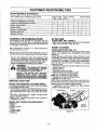
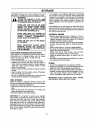
CLEAN AIR FILTER (Fig. 12)
A dirty air filter decreases the life and performance of the
engine and increases fue! consumption and harmful
emissions
Always clean your air filter after 5 tanks of fuel or 5 hours
of operation, whichever is less. Clean more frequently in
dusty conditions. A used air filter can never be completely cleaned. It is advisable to replace your air filter with a
new one after every 50 hours of operation or annually,
whichever is less.
• Remove the two screws and the air filter cover from the
engine. Figure 12.
• Remove air filter.
= Wash filter in soap and water.
• Squeeze filter dry and replace in cover.
, Add 4 or 5 drops of oil to the air filter.
NOTE: Do not soak the air filter with oil.
• Squeeze the air filter to distribute the oil.
• Reinstallthe air filter cover.
NOTE: When reinstalling the air filter, be sure the air filter is fitted into the comers of the cover to keep dust from
entering engine and causing engine damage.
• If replacing the air filter, contact your Sears Service
Center for the proper part.
AIR FILTER
COVER
PARTS
COVER
SCREWS
• Throttle
trigger
Handle screws
• Fasteners
Figure 12
-14-
CUSTOMER
CHECK
OR REPLACE
BLADE
(Fig.
RESPONSIBILITIES
13)
WARNING:
THE BLADE WILL CONTINUE TO SPIN
AFTER THE ENGINE STOPS OR AFTER THE
THROTTLE
TRIGGER
HAS
BEEN
RELEASED. MAKE SURE THE BLADE HAS
STOPPED COASTING AND DISCONNECT
THE SPARK PLUG BEFORE PERFORMING
WORK ONTHE BLADE.
ALWAYS REPLACE A BLADE THAT IS BENT
WARPED, CRACKED, BROKEN OR DAM_
AGED IN ANY OTHER WAY. NEVER
ATTEMPT TO STRAIGHTEN AND RE-USE A
DAMAGED BLADE. USE ONLY RECOMMENDED SEARS REPLACEMENT BLADES.
WEAR PROTECTIVE GLOVES WHEN HANDLING OR PERFORMING MAINTENANCE
ON THE BLADE TO HELP AVOID INJURY.
i
The blade is reversible. When the cutting edge on one
side becomes worn, turn the blade over.
Check blade for flatness periodically.. Lay the blade on a
flat surface and inspect the blade for flatness.Throw away
a blade that is not fiat.
TO REPLACE THE BLADE:
• Bind the blade by inserting a screwdriver into the hole
in the gearbox.Fig. 13..Then, remove the nut, washer,
and blaae from the blade shaft.
• Reverse the blade, or replace it with the recommended
Sears replacement blade.
• Place the blade on the blade shaft, match the flat area
of the blade opening with the fiat side of the shaft,
• Install washer, making sure to install the cupped side
facing the blade.
• Install the nut by threading counterclockwise on the
blade shaft.
• Bind the blade by inserting a screwdriver into the hole
in the gearbox and tighten the nut with a wrench unti!
the washer is flattened firmly against the blade.
SPARK PLUG
BOOT
SPARK
PLUG
Figure 14
REPLACE
FUEL FILTER (Fig. 15 & 16)
The fue! filter should be reptacedatter each season.
Never operate your edger without a fuel filter. Be careful
not to damage fuel line while removing the fuel filter.
• Run fue! tank dry of fuel before replacing fue! filter.
• Move "On/Off" switch to the "Off" position.
• Remove the fue! cap and allow it to hang to side of
motor.
• Using a s-mall pair of needle nose pliers, grasp fuel cap
retainer, holding it in tank opening and pull out.
• With cap out of tank, use a small section of bent wire
similar to that shown in the illustration to catch fuel line
and slowly pull from tank. When fuel filter appears in
opening, grasp with fingers and remove from tank.
• Once filter is out of tank, hold fuel line close to fuel filter. Remove fuel filter by twisting and pulling at the
same time.
, Replace fuel filter.
• Reverse process for installation.
RETAINER
\
FUELCAP
EDGER BLADE
Figure 15
Figure 13
YEARLY
REPLACE THE SPARK PLUG (Fig. 14)
FUEL
FUEL LINE
The spark plug shoutd be replaced each year to ensure
the engine starts easier and runs better.
Spark Plug gap should be .025"
° Twist, then pull off the spark plug boot.
• Remove spark plug from cylinder and discard.
• Replace with correct spark plug and tighten with 3/4"
socket wrench (10-12 ft-lbs.)
_
FILTER
Figure 16
-15-
SERVICE AND ADJUSTMENTS
CARBURETOR
ADJUSTMENTS
Carburetor adjustment is critical and if done improperly can permanently damage the engine as well as
the carburetor. Please read all instructions and consuit the Troubleshooting section of this manual
before beginning this process. If the engine does not
operate according to these instructions after repeating the adjusting steps, do not use the unit. For further assistance, please call our customer assistance
hotline at 1-800-235-5878.
i_
SERIOUS
INJURY TO THE OPERATOR
WARNING:
AND OTHERS CAN OCCUR IF THE CARBURETOR IS NOT PROPERLY ADJUSTED. KEEP OTHERS AWAYWHEN MAKING
CARBURETOR ADJUSTMENTS.
THE
BLADE SHAFT WILL BE SPINNING DURING MOST OF THIS PROCEDURE. WEAR
YOUR PROTECTIVE EQUIPMENT AND
OBSERVE ALL SAFETY INSTRUCTIONS.
CARBURETOR
PRESETS
(Fig. 17)
If your engine will not start d_e to suspected improper
carburetor adjustment, the following presets may be required. If used, it is recommended that all steps within the
adjustment procedure be completed in order to assure a
properly set carburetor. If presets are not needed, proceed to section "Idle Speed Adjustment."
When making adjustments, be careful not to force the
ptastic limiter caps beyond the stops or damage will
occur.
Very small adjustments can affect engine performance. It
is importantto make slight adjustments and test performance before proceeding. Each adjustment should be no
more than 1/16 of a turn.
• Turn both of the mixture adjustments counterclockwise to the stops.
• Turn the idle speed adjustment clockwise until il
stops. Now turn counterclockwise 3 turns.
* if engine fails to start after performing carburetor presets, the unit may be flooded. Review the "Difficult
Starting" section of the manual. If problems continue
call the 1-800 number listed on the front cover of this
manual for further assistance.
• Start the engine and operate for three (3) minutes to
warm up. Go to "AdjustingProcedure:
REMOVE BLADE BEFORE MAKING CARBURETOR
ADJUSTMENTS.
DO NOT
MAKE ADJUSTMENTS FROM THE BLADE
SIDE OF THE UNIT. HOLD THE UNIT WITH
YOUR HAND.
RECHECK IDLE SPEED AFTER EACH
ADJUSTMENT.THE BLADE SHAFT MUST
NOT TURN AT IDLE SPEED TO AVOID
SERIOUS INJURY TO THE OPERATOR OR
OTHERS.
ADJUSTING
If engine does not start, it may be flooded. If in doubt,
read the section on flooded engine in the starting section
of this manual prior to beginning any adjustments.
The carburetor has been adjusted at the factory for sea
level conditions. Adjustments may become necessary if
the saw is used at significantly higher altitudes or if you
notice any of the following conditions:
• Engine will not continueto run at idle position. See "Idle
Speed Adiustment"
and "Low Speed Mixture
Adjustment."
• Blade continues to spin when engine idfes. See "Idle
Speed Adjustment _.
• Engine dies or hesitates when it should accelerate.See
"Acceleration Adjustment."
• Loss of cutting power whichis not corrected by air filter
cleaning. See "High Speed Mixture Adjustment:
• Engine will not run. See "Trouble Shooting Chart:Then,
if the carburetor requires adjustment, begin with "Basic
carburetor Settings:'
NOTE: There are three adjustments on the carburetor.
• The Idle Speed Adjustment is marked with the letter
"T7
* The two remaining adjustments on the carburetor are
the mixture adjustments. One is marked "L" for low
speed, and the other "H" for high speed.
-16-
PROCEDURE
IDLE SPEED ADJUSTMENT "T"
• Allow the warm engine to idle.
° Adjust the Idle Speed untilthe engine continues to run
without stallingand without the blade shaft moving.
- Turn clockwise to increase engine speed if engine
stalls or dies.
- Turn counterclockwise to slow engine down and/or to
keep the blade shaft from turning.
• No further adjustments are necessary if blade shaft
does not move at idle speed and if performance is satisfactory.
ACCELERATION CHECK
• If the engine dies or hesitates instead of accelerating,
turn the Low Speed Mixture Adjustment 1/16 of a turn
at a time counterclockwise until you have smooth acceleration.
* Check the idle speed for stability and no blade movement. Adjust as necessary.
-Recheck for smooth acceeration and stable idle.
Repeat process as necessary for acceptable perfor*
mance.
LOW SPEED MIXTURE ADJUSTMENT "L"
• Allow engine to idle.
• Turn the Low Speed Mixture Adjustment slowly clockwise until the RPM starts to drop. Note the position.
, Turn the Low Speed Mixture Adjustment slowly counterclockwise until the RPM speeds up and starts to
drop again. Note the position.
• Set the Low Speed Mixture at the midpoint between the
two positions.
Readjust idle speed. See _ldle Speed Adjustment:
-" Repeat Acceleration Check for acceptable performance.
SERVICE AND ADJUSTMENTS
HIGH SPEED MIXTURE ADJUSTMENT "H"
IMPORTANT: DO NOT OPERATE ENGINE AT FULL
THRO'I-I'LE FOR PROLONGED PERIODS WHILE MAKING HIGH SPEED ADJUSTMENTS AS DAMAGE TO
THE ENGINE CAN OCCUR.
• Disconnect spark plug wire.
• Remove the three rubber screw hole plugs using needle nose ptiers. Fig. 18.
• Remove the three gear box screws. Fig. 18.
• Separate the gear box from the engine.
SCREW HOLE PLUGS
GEAR BOX SCREWS
• Support the unit so the blade shaft will not make contact with any object. Do not make adjustments from the
blade side of the unit.
• Allow the engine to idle, then squeeze the throttle trig;
geer fully.
NOTE:Perform next two steps at full throttle.
Turn the screw the minimum amount clockwise until the
engine runs smoothly. Do not attempt to turn the
screws beyond the stopsas damage can occur.
• If the engine accelerates and runs smoothly, no further
adjustments are necessary.
• Recheck and follow steps in "Acceleration Check" and
"Idle Speed Adjustment".
LOW SPEED
HIGH SPEED
MtXTURE
Figure 18
• Set the gas tank and fuel line retainer plate aside.
• Hold the =Flats"of the clutch with an adjustable wrench
as shown in Figure 19 (inset). Remove the nut counterclockwise with a box wrench or another adjustable
wrench.
NOTE: The clutch assembly will slide off the crankshaft
intact. Do not disassemble the clutch assembly.
° Remove the cfutch assembly.
MIXTURE
'_BEVELED
ADJ
_
Figure 17
_.._UT
STARTER ROPE REPLACEMENT
(Fig. 18, 19, 20,21
_
&
& 22)
NEVER START THE ENGINE WITH GEAR
BOX REMOVED; THE CLUTCH CAN FLY
APART AND CAUSE SERIOUS INJURY.
_)-,_F-CLUTCH
I"<----NUT
_,.._
DANGER:
WASHER
_TARTER
-8
CUP
_._.PULLEY
Figure 19
• Remove broken piece of rope, if any. Figure 20.
• Hand turn the pulley counterclockwiseas far as it will
go.Then, turn the pulley clockwiseuntil the pul}eynotch
is aligned with the housing notch next to the retaining
tab and screw.Figure 20.
° Next, turn the pulley one complete turn clockwiseuntil
the notchesare aligned again.
• Insert the small hex wrench into hole formed by the
notches to hold pulley in position.Figure 20 (inset).
• Use a 72" (1.83meter) length of replacement rope.
• Move 10 feet (3 meters) away from the fuel tank with
the replacement rope. Use a match and melt both ends
of the rope to prevent fraying.
° Pull melted ends through a thick, clean rag while rope
is still hot to obtain smooth, pointed ends.
• Insert one end of the rope through the handle and
secure with a knot. Leave a 3/16 inch (4.8ram) tail
behind the knot. Figure 20 (inset),
DO NOT REMOVE THE WIRE CLIP TO
REMOVE THE PULLEY. THE SPRING
BENEATH THE PULLEY tS UNDER TENSION
AND CAN FLY OUT AND CAUSE SERIOUS
INJURY. IF ANY PART OF PULLEY HOUSING
ASSEMBLY IS DAMAGED OTHER THAN THE
ROPE, DO NOT USE THE UNIT. TAKE IT TO
YOU SEARS SERVICE CENTER.
USE ONLY HAND TOOLS TO REMOVE THE
CLUTCH. DO NOT USE ANY TYPE OF
MOTORIZED TOOLS OR STRIKE THE
CLUTCH IN ANY WAY. DOING -SO CAN
CAUSE THE CLUTCH TO FLY APART
RESULTING IN SERIOUS INJURY.
BE SURE THE CLUTCH IS COMPLETEL_
SEATED ON THE STARTER CUP BEFORE
INSTALLING THE WASHER AND NUT. THE
POSTS ON THE UNDERSIDE
OF THE
CLUTCH MUST BE POSITIONED IN THE
HOLES IN THE STARTER CUP.
WHEN REINSTALLING THE GEAR BOX,
MAKE SURE THE ROPE EYELET IS ASSEMBLED IN THE NOTCH ON THE SHROUD.
- 17-
SERVICE AND ADJUSTMENTS
RETAINER
SCREW
_T
ROPE
PULLEY
HOLE
RIB
RETAINER
"SCREW/POST
Figure 20
• Insert the end of the rope through the eyelet on the trigger handle, then through the eyelet in the notch on the
engine shroud. Figure 21.
• Insert one end of the rope into the pulley and up
through the pulley hole. Figure 20.
• Leave a 1 inch (2.5cm) tail laying between the retainer
rib and the retainer screw post. Figure 20.
• Tighten the rope retainer screw until the bottom of the
rope retainer is snug.
• Hold the rope taut at the rope exit hole so the pulleywilt
not move. Remove the hex wrench and slowly feed the
rope into the pulley.
• Follow steps for disassembly to reinstall.
PULLEY
NOTCH
Figure 21
EYELETS
Figure 22
-18-
STORAGE
Immediately prepare your unit for storage at the end of
the season or if it will not be used for 30 days or more.
WARNING':
4_b
ALLOW
TO COOL,
AND
SECURE THE
THE ENGINE
UNIT BEFORE
STORING
OR TRANSPORTING IN A VEHICLE.
STORE UNIT AND FUEL IN AN AREA
WHERE FUEL VAPORS CANNOT REACH
SPARKS OR OPEN FLAMES FROM
WATER HEATERS, ELECTRIC MOTORS
OR SWITCHES, FURNACES, ETC.
Fuel stabilizer is an acceptable alternative in minimizing
the formation of fuel gum deposits during storage. Add
stabilizer to the gasoline in the fuel tank or fuel storage
container. Always follow the mix instructions found on stabilizer containers. Run engine at least 5 minutes after
adding stabilizer to allow the stabilizer to reach the carburetor.
CRAFTSMAN 40:1 2-cycle engine oil (AIR-COOLED) is
specially blendedwith fuel stabilizer. If you do not use this
Sears oil, you can add a fuel stabilizer (such as craftsman
No. 33500) to your fuel tank.
STORE UNIT WITH ALL GUARDS IN
PLACE. POSITION SO THAT ANY SHARP
OBJECT
CANNOT
ACCIDENTALLY
CAUSE INJURY TO PASSERS BY.
INTERNAL
STORE THE UNIT OUT OF THE REACH
OF CHILDREN.
WEAR PROTECTIVE GLOVES WHEN
HANDLING
BLADE. THE BLADE IS
SHARP AND CAN CUT YOU EVEN WHEN
IT IS NOT MOVING.
GAS EDGER STORAGE INSTRUCTIONS
If your edger is to be stored for a period of time, clean it
thoroughly prior to storage. Remove any dirt, grass,
leaves, oil, grease, etc. Store in a clean dry area.
• Clean the entire unit.
• Clean air filter. Refer to "Customer Responsibilities."
• Inspect the guard area and ctean any dirt, grass, or
debris that has collected. Inspect the blade; replace a
blade that is bent, warped, cracked, broken, or damaged in any other way.
• Ughtly oil external metal surfaces to prevent rust from
forming.
• Apply a coating of oil to the entire surface of the blade;
wrap it in heavy paper, or cloth.
• Be sure all handles and guards are in place and are
securely fastened. Replace any damaged parts.
FUEL SYSTEM
Never use engine or carburetor cleaner products in the
fuel tank or permanent damage may occur to fuel system
components. Follow these instructions:
• Drain the fuel from the unit into an approved fuel container.
* Drain the fuel lines and carburetor by starting the
engine and letting it run until it stops.
- Allow the engine to cool before storage.
IMPORTANT: It is important to prevent gum deposits
from forming in essential fue! system paris such as the
carburetor, fuel filter, fuel hose or tank during storage.
Also, experience indicates that alcohol blended fuels,
those that use ethanol or methanol (called gasohol or
oxygenated fuel), can attract moisture and form acidic
gas whichwill damage your engine.To avoid engine problems, the fue! system should be emptied before storage
of 30 days or longer.
-19-
ENGINE
° Remove spark plug and pour 1 teaspoon of 40:1 2*
cycle engine oil (AIR-COOLED) through the spark plug
opening. Slowly pull the starter rope 8 to 10 times to
distribute oi! to inner engine surfaces.
• Replace spark plug with a new one of the recommended type and heat range. Refer to "Product Specifications:'
• Clean air filter. Refer to "Customer Responsibilities."
• Re-install all covers and hardware removed for access;
tighten all screws and fasteners.
• Check entire unit for loose screws, nuts, and bolts.
Replace any damaged, broken, or worn parts.
• Lightly oil external metal surface to prevent rust from
forming.
• Use fresh fuel having the proper gasoline to oil ratio at
the beginning of the next season.
OTHER
• Do not store gasoline from one season to another.
• Replace your gasoline can if your can starts to rust. Rust
and/or dirt in yourfuel system will cause problems.
- Store your unit in a welt ventilated area and covered, if
possible, to prevent dust and dirt accumulation. Do not
cover with plastic. Plastic cannot breathe and wilt
induce condensation and eventual rust or corrosion.
IMPORTANT: NEVER COVER UNIT WHILE ENGINE
AND EXHAUST AREAS ARE STILL WARM.
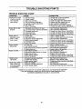
TROUBLE SHOOTING POINTS
TROUBLE
SYMPTOM
SHOOTING
CHART
CAUSE
CORRECTION
1. Fill tank with correct fuei mixture.
Engine wili not start
1. Fuel tank emptY.
2, See "Starting Instructions."
or will run only for
2. Engine flooded.
3, Install new plug/check fgnition switch.
a few seconds
3. Spark plug not firing,
4, Replace fuel filter; inspect fuel line.
after starting.
4+ Fuel not reaching carburetor.
5. See "Carburetor Adjustments?
5. Carburetor requires adjustment,
6. Move switch to the "START" position.
6. Stop switch off.
7. None of the above.
7. Contact your Sears Service Center/Dept.
=l =1.
Engine will not iclle........................
1. Idle speed set too fast or too sJow.
1. See "Carburetor Adjustments."
properly,
2. Low speed mixture requires adjustment. 2. See "Carburetor Adjustments."
3, Crankshaft seals worn,
3. Contact your Sears Service Center/Dept,
4. Contact your Sears Service Center/Dept.
4, Compression low.
5. None of the above.
5. Contact your Sears Service Center/Depto
1. Clean or replace air filter.
Engine will not
1. Air fiiier dirty.
2. Clean or replace spark plug and re-gap.
accelerate, lacks
2, Spark plug fouled.
3. See =Carburetor Adjustments,"
power, or dies
3. Carburetorrequires adjustment.
4. Contact your Sears Service Center/Dept.
under a load,
4. Muffler outlets plugged.
5. Compression tow.
5. Contact your Sears Service Center/Dept.
6. None of the above.
6. Contact your Sears Service Center/Dept,
1. Clea[_'or replace air fifter.
Engine smokes
1. Air fii{er dirty.
2. Refuel with correctfuel mixture.
excessively.
2+ Fuel mixture, incorrect.
3. High speed mixture requires adjustment. 3. See =Carburetor Adjustments."
4. Rotate choke to "Off position.
4. Choke partially on.
1. See "Fueling Your Unit;
Engine runs hot.
t. Fuel mixture incorrect.
2. High speed mixture set too low (Lean),
2. See "Carburetor Adjustments,_
3. Replace with correct plug.
3. Spark plug incorrect.
4. Muff+oroutlets plugged.
4. Contact your Sears Service Center/Dept.
5+ None of the above.
5. Contact your Sears Service Center/Dept.
Blade turns"at
11 Idle speed requires adjustment. .....
1. See =Carburetor Adjustme'nts,."
2. Replace or repair throttle cable,
idle speed.
2. Throttle cable binding.
3. Clutch requires repair.
3. Contact your Sears Service Center/Dept.
Blade stops under a
1. Blade not engaged+
1. Check gearbox.
2. See "Carburetor Adjustments+"
load or does not
2. Carburetor requires adjustment.
3, Contact your Sears Service Center/Dept.
turn when engine
3. Clutch requires repair,
is accelerated
If situations occur which are not covered in this manual, use care and good judgement,
If you need assistance, contact your SEARS Service Center/Department or the
CUSTOMER ASSISTANCE HOTLINE at 1.800o235-5878,
- 20 -
i
.i.. rl
,..i.
ii
HHH I,IIIIIIIIIIII
I
.....I.
I..
II
.IHHI I
I
,,,,
,,,,,,,,,,,,,,,,,,,,,,,,,,
,,,,,,,,,
,
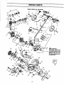
REPAIR PARTS
i
iiiiii i
i i
ii
IIIHIIIIII
I
II
I
IIIIIIIIIIIII
IIIIIIIIIIII
III
IIIHIIIIIII
I
I
IIII
II III
I
SEARS MODEL NO. 358.797450
/
31.
/
/
110.
\
/
109.
121.
/
118. 122. 119.
120.
:-21-
/
104.
IIII
IIIIIIIII
,,,,,,,
=
= =
=
REPAIR PARTS
SEARS MODEL NO. 358.797450
ReL
Part No.' ..........
Re£
Description
Hi
L
2.
3,
4.
5.
6,
7,
8_
9.
10.
11.
12.
13.
14.
15,
16.
17.
18.
19.
20.
2!.
22.
23.
24.
25.
26.
27.
28.
29.
30.
31.
32.
33.
34.
35.
36.
37.
38.
39,
40.
41.
42.
43.
44.
45.
46,
47.
48.
49.
50.
51.
52.
53.
54.
55.
56.
57,
58.
59,
60.
6L
62.
63.
64.
65.
66.
67.
68.
69.
70.
71.
72.
73.
530-036677
530-036985
530-015241
530-036981
530- 036676
530-015768
530-036982
503-210719
530-047628
530-036984
530-095104
530-015999
530-036983
530-016002
530-015997
530-095126
530-015982
530-095103
530-015983
530-047588
530-036837
530 -O36664
530 - 036674
530 -016038
530-038474
530-037066
530-014707
530-015922
530-015774
530-015886
530-015810
530 -047584
530-036927
530-015828
530-047585
530-01594O
530-015954
530-014655
530-039163
530-036145
530--027569
530-069421
530 -015774
530-039148
530-015945
530-019179
530-014861
530-014864
530-019181
530-047585
530-032124
530-015941
530-032125
530-036404
530-015934
530-069615
530-015162
530-019223
530-069621
530-015953
530-030075
530-069619
530-019185
530-047587
530-016014
530-019194
530-069654
530--036626
530-019190
530 -036622
530--015887
530-023877
530 -038308
irr ,i
P'=Part Change
Pa_ No.
Description
H
Upper Handle
Handle Eyelet
Screw-Eyelet
Spring Isolator
Lower Handle
Locknut - Coupling/Shaft
ThrottleSpring
Screw-Handie
Throttle Trigger
HandleSpring
Upper Handle Tube
Screw-ShaR
Coupling-Handle
Bridgepin
Axle Pin
Rear Wheel
Tube Clamp
Lower Handle Tube
Screw- Filter Cover
Air Filter Cover
Gasket
Air Fiber Foam
Throttle Cable
Boot w/Nut
Switch Indicating Plate
Grounding Terminal
Switch Grounding Assy(Incl.
24-26)
Speed Nut
Serew-Fan
Housing
Serew-Fan
Housing
Screw-Fan
Housing!Shroud
Fan Housing
Flywh_l Spacer
Washer
Axle Cover
Screw-Fan Housing
Screw- Ignition
Module
Switch W'_ Ass'y.
Ignition Module
Spacer- Ignition Module
Starter Handle
Pope Kit
Screw- Coupling
Flywheel Ass'y.
RetainingRing- C'case
C'caseSeal
Cr_
Ass'y. (hcl. 45, 46, 51 & 52)
CrankshaftAss'y.
Gasket-Crankcase
Shroud
Outer Bearing
Retaining Ring-C'shaft
Inner Bearing
PistonRing
Screw-Shroud
Connecting Rod Ass'y. (Iucl. 53)
Piston Pin Retainer
Gasket- Cylinder
PistonKit (IncL 54)
Serew- Cylinder
Spark Plug (RCJ- BY)
Cylinder Kit
Gasket - Cyllnder/Carb
Adaptor
Carb. Adaptor
Screw-Carb
Adaptor
Gasket - Carburotor
Carburetorw/Choke
Air Box Base
Foam Seal
Airbox Cover
Serew-Airbox
Cover
Fuel Line Fitting
Fuel Line Retainer
75.
76.
77.
78.
79.
80.
81.
82.
83.
84.
85.
86.
87.
88.
89.
90,
91.
92.
93.
94.
95,
95.
97.
98.
99.
100.
i01.
102.
103.
530-036180
530-019144
530-029930
530-016033
530-016032
530-059660
530-037229
530-069418
530-037224
530-036679
530-019199
530-027162
530-042073
530-042072
530-036922
530-014832
530-015127
530-069598
530-014815
530-014370
530-047195
530-036792
530-626605
530-036665
530-095082
530-015843
530-036935
530-015770
530-037367
530-069624
104.
105.
530-095086
530-014906
106.
107.
108.
109.
110.
111.
112.
113.
114.
115.
116.
i17.
118.
119.
120.
121.
122.
123.
124.
530-037625
530-016067
530-016040
530-095070
530-015814
53O-014894
530-036675
530-036923
530-036683
530-027163
530-016063
530-015981
530-095125
530-037279
530-015515
530-036884
53O-O01717
530-015151
530-016042
74.
Muffler Screen
Gasket- Bracket
Muffler Spring
Washer-Blade
Nut-Blade
Muffler Kit (Ind, 76)
Starter Spring
Starter Pulley Kit (Incl. 3, 83 & 85)
Eyelet
Rope Retainer
Gasket- Tube
Starter Dog
Starter Cam
Starter Dog V_Lre
Starter Cup
ClutchAss'y.
Washer -BeUeville
Fuel Line Kit
Fuel Pick-up Ass'),.
_ael Cap Ass'y.
Fuel Tank Ass'y.
Fue! Tauk Isolator
Nut
Drum Clutch
Front Shield
Screw
Dustplug
Screw-Bearing
Holder
Bearing Holder Ass'y.
GasketKit
(ha!. 21,49,58,63,66,& 75)
Bhde
C'cz_se & C'shafl Ass'y.
(Incl, 45-48, & 51-53)
Retainer Ring
ShouJderBolt
Washer
Drive Shaft
Screw
Gear Box .Ass'y.
Back Plate
s_
Height Lever
Retainer-Stert_
Pulley
Nut-Swing Arm
Bolt-Front Wheel
Front Wheel
SwlngArm
Locknut-Swing
Arm
Front Axle Spring
Washer- Thrust
Washer - Fiat
Washer-Thrust
Not _lhown
530-086377
530-014658
530-085351
530-047589
530-036958
530-047593
530-031159
, ,,,,,
==
-22-
OperatorManual
Carton
Contents
Bag
Car_n
Starting Instruction Decal
Blade Shield Decal
Shaft Warning Decal
He_ Wrench 5/32
,,
,,,,,H,=,,=
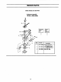
SEARS MODEL NO. 358.797450
Carburetor
Assembly
WT 308 - #530-069654
1
P,,ef.
-23-
Part No.
L
530-069658
2.
53O-069712
3.
4.
530--038317
530--038318
2
Description
Carbur_r
Repair Kit
(• hdicatas 'Contents)
Primer Bulb Rep_drKit
( _ Ia_ates
Contents)
Limiter Cap- Low
!Limiter Cap-High
NOTES
-24-
NOTES
-25-
NOTES
- 26-
SE4/k tS
CRAFTSI4AII
®
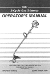
Operator's
Manual
1.3 cu. in./21cc 2-CYCLE
Gear Driven
GASOLINE EDGER
Model No.
358.797450
IFYOU NEED REPAIR
SERVICE OR PARTS:
REPAIR SERVICE
1-800-4-REPAIR
(1-800-473-7247)
ORDERING PARTS
1-800-FON-PART
(1-800-366-7278)
Each Gasoline Edger has its own model number. The model
number for your unit will be found on a decal attached to the
unit.
All parts listed herein may be ordered from any Sears, Roebuck
and Co. Service Centers and most Retail Stores.
WHEN ORDERING REPAIR PARTS, ALWAYS GIVE THE
FOLLOWING INFORMATION AS SHOWN IN THIS LIST:
• PRODUCT-"GASOLINE
EDGER"
• MODEL NUMBER - 358.797450
• PART NUMBER
• PART DESCRIPTION
Your Sears Merchandise has added value when you consider
that Sears has service units nationwide staffed with Sears
trained technicians.., professional technicians specifically
trained on Sears products, having the parts, tools and equipment to insure that we meet our pledge to you, we service what
we sell.
HOURS (CST)
Mon.- Sat. 7 a,m. - 7 p.m.
Sun.10 a.rn.- 7 p.m.,
Sears,
Roebuck and Co., Hoffman
Estates,
IL 60179 U.S.A.