1
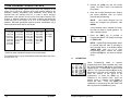
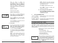
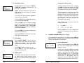
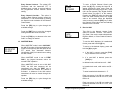
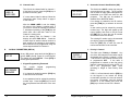
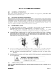
TABLE OF CONTENTS How To Program Radios ................................................................................2 Keypad Programming ....................................................................................2 A. Navigation........................................................................................3 1. Group Parameters (CH 00) ......................................................4 2. Channel Parameters (CH 01 - CH20) .......................................4 3. Global Parameters (GRP 00)....................................................5 B. Group Parameters (CH 00)...............................................................5 1. Group Options: 1-12345678 .....................................................5 2. Group Label.............................................................................6 C. Channel Parameters (CH 01 - CH20)................................................7 1. Channel Bandwidth..................................................................7 2. Receive Frequency ..................................................................8 3. Receive Mode .........................................................................8 4. Receive Guard.........................................................................8 5. Receive NAC...........................................................................9 6. Squelch Mode .......................................................................10 7. Transmit Frequency ...............................................................10 8. Transmit Mode.......................................................................11 9. Transmit Guard......................................................................11 10. Transmit NAC........................................................................12 11. Talk Group ID ........................................................................13 12. Channel Label .......................................................................14 D. Global Parameters (GRP 00) ..........................................................14 1. Keypad Programming Password ............................................14 2. Automatic Numeric Identification (ANI) ...................................15 3. Priority 1 Channel ..................................................................15 4. Priority 1 Group .....................................................................16 5. Priority 2 Channel ..................................................................16 6. Priority 2 Group .....................................................................17 7. Transmit On Priority 1 ............................................................17 8. Old-Style BK Priority Scan .....................................................17 9. Priority 1 Lock........................................................................18 10. Scan List Lock .......................................................................18 11. Transmitter Time-Out Timer ...................................................18 12. Scan Delay Time ...................................................................19 13. Busy Channel Operation ........................................................19 14. ANI/DTMF Mode....................................................................20 15. Backlight Triggers ..................................................................21 16. Backlight Duration..................................................................22 17. Silent Mode ...........................................................................22 18. Battery Saver.........................................................................22 19. Review Global Parameters (GRP 00) .....................................23 E. Exit Programming Mode .................................................................23 Cloning Radio Settings.................................................................................23 Tone Channel Guard Values ........................................................................26 Digital Channel Guard Values.......................................................................27 Keypad Programming Manual 1 HOW TO PROGRAM RADIOS DIGITAL CHANNEL GUARD VALUES You can program DPH-CMD radios in three different ways: Codes for the Digital Channel Guard system may be chosen from the following list. This can be done during the code programming of the system. Usually systems using direct unit to unit transmission (systems without mobile relays, repeaters, remote control, etc) may use codes from the table. Systems with relays etc. may use code variations for system control and operational efficiency. The system operator or engineer should be consulted regarding the operational requirement on such systems. A. BY KEYPAD A radio can be programmed with its keypad and a programming plug, LAA0701. That procedure is described in this manual. B. BY CLONING You can transfer a radio’s programmed settings to another DPH-CMD or DPH radio by using a cloning cable, LAA0700. See "Cloning Radio Settings" in this manual. C. BY COMPUTER With a computer, DPH-CMD programming software and an LAA0725 interface cable. That procedure is not described in this manual. Contact BK Radio for the programming cable and required software. KEYPAD PROGRAMMING Some radios are shipped with a door covering the keypad and display. Before programming, remove the door by removing the battery pack, engaging the door just below the speaker grill, and sliding the door downward. Replace the battery pack. 023 025 026 031 032 043 047 051 054 065 071 072 073 074 114 115 116 125 131 132 134 143 152 155 156 162 165 172 174 205 223 226 243 244 245 251 261 263 265 271 306 311 315 331 343 346 351 364 365 371 411 412 423 431 432 445 464 465 466 503 506 516 532 546 565 606 612 624 627 631 632 654 662 664 703 712 723 731 732 734 743 754 Make sure the battery pack is charged. Master Switch 1. Insert the programming plug into the side connector of the radio. The push-button master switch will be on the top. NOTE: The cloning cable can be used as a substitute for the programming plug by inserting the end with the push-button master switch into the side connector of the radio. 2. Select a channel group to be programmed. Programming Plug 3. Press and hold the master switch. PSWRD-****** 4. While holding the master switch, press and hold the [FCN] key. After approximately three seconds the LCD will display ’PSWRD-******‘. 2 BK Radio Keypad Programming Manual 27 5. Release the [FCN] key and the master switch. The radio is now in the Password Entry Mode. TONE CHANNEL GUARD VALUES The Tone Channel Guard system may be set for any frequency in the range of 67 to 255.9 Hz. However, since most systems adhere to the Electronic Industry Association (EIA) standards, tones should be selected from the following EIA list. In order to insure optimum performance, tone selection for use on the same radio frequency (RF) channel or adjacent channels in the same coverage area should be made from one of the Groups A, B, or C to the maximum degree possible. BK Radio guarantees optimum receiver performance only if tone frequencies below 220 Hz are chosen. GROUP A 67.0 (XZ) *151.4 (5Z) 77.0 (XB) 162.2 (5B) 88.5 (YB) 173.8 (6A) *100.0 (1Z) 186.2 (7Z) 107.2 (1B) 203.5 (M1) 114.8 (2A) 218.1 (M3) 123.0 (3Z) 233.6 131.8 (3B) 250.3 141.3 (4A) GROUP B 71.9 (XA) 146.2 (4B) 82.5 (YZ) 156.7 (5A) 94.8 (ZA) 167.9 (6Z) 103.5 (1A) *179.9 (6B) 110.9 (2X) 192.8 (7A) *118.8 (2B) 210.7 (M2) 127.3 (3A) 225.7 (M4) 136.5 (4Z) 241.8 GROUP C 74.4 79.7 85.4 (YA) 91.5 (ZZ) 6. Enter the six-digit password code. Without the correct password code, you cannot proceed with programming. NOTE: New radios shipped from the factory are assigned the password code 000000. If the password code is entered incorrectly, the radio will reset to normal operation. Try again, starting at step 2. PRG ch 7. Press the [ENT] key to proceed to Programming Mode. The display will change to ‘PRG CH 00’. 00 NOTE: Keypad Programming Mode cannot be entered when the radio is operating in the Command Group. If the display flashes “CMND GRP” when you try to enter Programming Mode, release the master switch and [FCN] key, and select a different group. * 50/60 Hz power distribution systems could cause falsing. The assignments in a given area shall be made from within one of the Groups: A, B, or C. 26 BK Radio A. NAVIGATION 1 2 3 FCN 4 5 6 PRI 7 8 9 ENT * 0 # CLR When Programming Mode is entered, programming starts (after password entry) with the Group Parameters (CH 00) for the currently selected group. To edit another Channel Group (GRP 01 - 25), press and hold the [#] key at any CH prompt to get the group selection prompt. Enter the number of the group to be programmed, or press the [PRI] key to increment to the desired group. Once the desired group is selected, press [FCN] to access the data. Press the [FCN] key repeatedly to cycle through the data fields, and then loop back to the CH 00 entry point. Keypad Programming Manual 3 1. Group Parameters (CH 00) include: 9. Once the data to be transferred have been selected, press the [FCN] key on the Master radio keypad. The top line of the display will flash ‘CLONING’ while the program in the master is being downloaded to the clone. Group Options: 1-12345678 (1-7 = undefined, 8 = group scan list bit) 10. If the download was successful, the display on the Master will again display the clone prompt (target and data to be transferred). Group Label To edit channel data, at the CH 00 prompt enter the number of the channel to be programmed, or press the [PRI] key to increment to the desired channel. Press the [FCN] key repeatedly to cycle through the data fields, and then loop back to the CH entry point. 2. Channel Parameters (CH 01 – CH 20) include: Bandwidth ([#] key at CH prompt toggles Wide/Narrow) • To clone Global Parameters, select Group 00 at the ‘GRP’ prompt. CLONING Group 01 • If cloning is finished, turn off the Clone and disconnect the cloning cable. Normal radio operation will occur when you turn on the Clone. FAILURE Group 01 11. If the download was not successful, the master will flash ‘FAILURE’ and multiple beeps will follow. Failure of downloading can be due to: RX Frequency RX Mode RX Guard RX NAC Squelch Mode TX Frequency TX Mode TX Guard TX NAC 1 2 3 FCN Talk Group ID 4 5 6 PRI Channel Label 7 8 9 ENT * 0 # CLR • Improper connection • Failure to turn on the clone • Setting the clone in Programming Mode To edit global data (GRP 00), press and hold the [#] key at any CH prompt to get the group selection prompt. Enter ‘0’ to select global data. Press [FCN] to access the data. Press the [FCN] key repeatedly to cycle through the data fields, and then loop back to the GRP 00 entry point. 4 • To clone another channel group, press the Master radio’s [CLR] key. Navigate to a ‘CH’ prompt, then press and hold the [#] key to get the ‘GRP’ prompt. BK Radio • Target radio’s group ‘locked’ by PC Programming NOTE: To stop the ‘FAILURE’ Mode, press [CLR], turn off both radios, and try again, starting with Step 1. Keypad Programming Manual 25 Master Clone NOTE: Some groups may be “locked” by PC programming to prevent them from being overwritten. Only “unlocked” groups will accept incoming clones. 3. Global Parameters (GRP 00) include: 1. Make sure the battery packs for both radios are charged. 2. Attach the master switch end of the cloning cable to the side connector of the Master radio. NOTE: One plug of the cloning cable has a push-button master switch. This plug must be attached to the Master radio. Master Switch 3. Turn on the Master radio. PSWRD-****** PRG ch 00 4. Put the Master radio in Programming Mode by pressing and holding the master switch then pressing and holding the [FCN] key until the display shows ‘PSWRD-******’. Enter the 6-digit password. The display shows ‘PRG CH 00.’ 5. Connect the other plug of the cable to the side connector of the radio you want to clone. 6. Turn on the clone and set it to the desired target channel group. Press and Hold [#] Key to Change Data PROG|DPHcmD PROG|DPHcmD Group 01 PROG|DPHcmD Cmnd group PROG|DPHcmD pick listS listS 24 7. Press the [*] key on the Master radio keypad. The radio will respond showing the prompt ‘PROG|DPHCMD’ on the first line and ‘Group XX’ on the second line, where XX is the currently selected group. (When cloning Global parameters, this will be ‘Group 00’). 8. Long [#] keypresses will cause the second line of the display to cycle through the data blocks that can be transferred to the target. B. Keypad Programming Password ANI ID PRI-1 Channel PRI-1 Group: (skipped if Channel = OFF or MAIN) PRI-2 Channel PRI-2 Group: (skipped if Channel = OFF or MAIN) TX on PRI-1 PRI-1 Lock Scan List Lock TX Time-Out Timer Scan Delay Busy Channel ANI/DTMF Backlight Triggers Backlight Duration Silent Mode Battery Saver GROUP PARAMETERS (CH 00) Press the [FCN] key at the CH 00 prompt to access group parameters. 1. Group Options: 1-12345678 This is a group of eight individual options that can be enabled or disabled. Target Valid Data GROUP 00 or GROUP 01 - 25 DPHCMD CMND GRP PICK LISTS BK Radio Keypad Programming Manual 5 NOTE: BK Radio current drain and battery life specifications are based on performance with the battery saver on. When an option is enabled, the corresponding number in the display will flash. When the option is disabled the number is steady. If you wish to change the option from enabled to disabled or vice versa, press the number key corresponding to that option. Press [PRI] to toggle the option on or off. Press [ENT] to store the setting and advance to the next field. Options 1 Through 7 19. Review Global Parameters (GRP 00) Reserved for future options. Press the [FCN] key repeatedly to display each setting in GRP 00, and then return to the GRP 00 starting point. Option 8: Group Scan List PRG 1-12345678 8 GRP OPTIONS When Option 8 is enabled (flashing) the current group will be scanned when the radio is operating in Group Scan Mode. 2. Group Label LABEL 1 GROUP LABEL EXIT PROGRAMMING MODE 1. Rotate the OFF-VOL knob counterclockwise to the OFF position. Press the [ENT] key to store the group options settings into memory and advance to the next field. Press the [FCN] key to advance to the next field without saving changes. PRG E. This field shows the label for the Channel Group. Each Channel Group can have a label of up to twelve characters or spaces. The characters can include 0-9, A-Z, –, -, ., *, +, <, >, /, \, |, $, %, h, or blank. 2. The radio will be in normal Operating Mode the next time it is turned on. CLONING RADIO SETTINGS Any “Master” radio (a DPH-CMD with the desired radio frequencies and settings) is capable of transferring its program to another DPHCMD radio. The radio receiving the program is referred to as the “Slave” or “Clone.” The LAA0700 cloning cable will be required in the following procedure. Data that can be cloned to another DPH-CMD radio includes: If no change is needed, press the [FCN] key to go back to the starting point for Channel 0 settings. NOTE: Special software available from BK Radio lets you enter Group Labels and Channel Labels from a computer. Contact your dealer for information. CMND CLN 6 BK Radio Group data (GROUP 1 – 25) Command Group data (CMND GROUP) Global data (GROUP 00) User Pick Lists (PICK LISTS) When the Master’s Command Group is cloned to a slave, the channel data that is ‘pointed to’ by the Command Group is transferred to a target group (not the Command Group) in the slave. The target group’s label in the slave will be set to “CMND CLN”. Keypad Programming Manual 23 16. Backlight Duration PRG 6 sec BL DURATION Changing The Group Label Backlight Duration can be set for LITE OFF, 1 SEC ON, 1-second increments up to 6 SEC ON, and LITE ON. Labels are edited from left to right. Pressing the [PRI] key moves the cursor to the next character. Pressing and holding the [PRI] key backspaces to the previous character. NOTE: Excessive battery drain will result if LITE ON is set and used for extended periods of time. The number keys 2 – 9 allow for entry of the letters printed on the respective keys. For example, the first press of the [2] key enters the letter A, the second press enters a B, the third press enters a C, and the forth press enters a 2. The letters Q and Z are entered with keys 7 and 9. If no change is needed, press the [FCN] key to advance to the next field. Press the [CLR] key to set backlight duration to zero and display LITE OFF. Keys 0 and 1 can be used to enter the following characters: Press the [PRI] key to increase backlight duration by 1 second increments from LITE OFF, to 1 SEC ON, 2, 3, 4, 5, 6 SEC ON, LITE ON (illumination remains on constantly) then back to LITE OFF. C. ON SILENT MODE When SILENT MODE is set to ON, all beeps, tones, and alerts from the radio’s speaker are silenced. Only normal audio communication between radio users will be heard. Press [PRI] to toggle the option on or off. Press [ENT] to store the setting and advance to the next field. 18. Battery Saver PRG ON BATTERY SAV 22 The Battery Saver should be turned off only for getting proper voltage readings during service or for systems requiring fast squelch attack time. BK Radio 1: 1, <, >, /, \, |, $, %, h CHANNEL PARAMETERS (CH 01 – CH 20) At the starting point for Channel 0, the display shows ‘PRG CH 00’. At this point, a channel number can now be entered to allow access to the settings for that channel. 17. Silent Mode PRG 0, space, –, _, ., *, + Press the [ENT] key to store changes and go back to the starting point for Channel 0 settings. Press the [ENT] key to store changes and advance to the next field. Press the [FCN] key to advance to the next field without storing changes. 0: 1. Channel Bandwidth PRG CH 01 N Press ‘1’ and the display will show ‘PRG CH 01’. This is the starting point for entering channel 1 values. At this point, pressing the [#] key will toggle the channel's bandwidth setting. An 'N' will appear to the right of the channel number when the channel is set for 12.5/15 kHz channel spacing using the narrow band receiver filter. A ‘W’ appears when the channel is set for 25/30 kHz channel spacing using the wide band receiver filter. Keypad Programming Manual 7 2. Receive Frequency PRG RX 148.00000 rx frequency Press the [ENT] key to store the changed setting and advance to the next field. Press the [FCN] key to move to the ‘RX FREQUENCY’ field. This is the receive frequency for channel 1 (in MHz). Press the [FCN] key to advance to the next field if no change is needed. 15. Backlight Triggers If the displayed frequency is correct, press the [FCN] key to advance to the next field. The backlight can be triggered by different events. If a new frequency is desired, press the [CLR] key followed by the digits of the desired frequency. Then press the [ENT] key to store this frequency and automatically advance to the next field. When BACKLIGHT is set to trigger on KEY PRESS, the display backlight will illuminate each time a key is pressed, even if pressing the key has no other effect. The display will not illuminate if backlight duration is set to LITE OFF. See "Backlight Duration” on page 22 of this manual. 3. Receive Mode PRG RX Analog Rx mode This field is the receive mode for channel 1. Available options are Analog, Digital, and Mixed. a. If the mode is correct, press the [FCN] key to advance to the next field. b. If a new mode is desired, press the [PRI] key to cycle through the mode settings. Press [ENT] to store the new mode and automatically advance to the next field. RX 000.0 rx guard Key or dsply BACKLIGHT When BACKLIGHT is set to trigger on DSPLY CHNG, the display backlight will illuminate each time the display receives input. This includes displayed changes in the selected channel or scan channel, and the PR, TX, and SCN annunciators. The display will not illuminate if Backlight Duration is set to LITE OFF. See "Backlight Duration" on page 22 of this manual. The BACKLIGHT can also be set to trigger on KEYPRESS OR DISPLAY CHANGE. 4. Receive Guard PRG PRG This field is the Analog Channel Guard value for Channel 1 receive. Press the [PRI] key to cycle through the available settings. NOTE: 0.0 indicates carrier operation (no Channel Guard). squelch Press the [ENT] key to store the changed setting and advance to the next field. If the displayed value is correct, press the [FCN] key to advance to the next field. Press the [FCN] key to advance to the next field if no change is needed. If a new value is desired, press the number keys 0 thru 9 to enter a Tone Channel Guard value. See "Tone Channel Guard Values" on page 26 of this manual. 8 BK Radio Keypad Programming Manual 21 Busy Channel Lockout - The yellow LED illuminates and the transmitter PTT is disabled when a signal is received without the programmed receive Channel Guard setting. PRG RX D 023 Rx Guard Busy Channel Override - This option is similar to Busy Channel Lockout except the transmitter PTT can be activated by rotating the Squelch knob clockwise off the Channel Guard detent. Press the [PRI] key to cycle through the available settings. Press the [ENT] key to store the changed setting and advance to the next field. Press the [FCN] key to advance to the next field if no change is needed. ANI AND DTMF ANI/DTMF 5. Receive NAC PRG RX $293 Rx nac This field is the Network Access Code (NAC) for Channel 1 receive. This value is only used if the receive mode selected was Digital or Mixed, or if User Channel Guard is activated. To see the NAC displayed in hexadecimal format, press and hold the [#] key. 14. ANI/DTMF Mode PRG To enter a Digital Channel Guard value press the [#] key, causing the letter ‘D’ to appear followed by three zeros. Enter the desired digital code using keys 0 thru 7 (keys 8 & 9 do not respond). See "Digital Channel Guard Values" on page 27 of this manual. Pressing the [PRI] key after the three-digit code has been entered allows the digital code to be inverted. When the displayed value is correct, press the [ENT] key to store the Channel Guard value and automatically advance to the next field. When ANI/DTMF mode is set to ANI ONLY, the ANI ID number will be transmitted (as a DTMF tone sequence) with each press of the PTT switch. See "Automatic Numeric Identification (ANI)" for instructions on setting the ANI number. When ANI/DTMF mode is set to DTMF ONLY, the keypad becomes active for manual DTMF operation. To return to the decimal display, press and hold the [#] key again. a. If the NAC is correct, press the [FCN] key to advance to the next field. b. If a new NAC is desired, press the [CLR] key. In decimal mode, valid entries are 0 – 4095. When ANI/DTMF mode is set to ANI AND DTMF, the ANI tone sequence will be transmitted only after the [ENT] key is pressed while the transmit PTT switch is activated. A sidetone of the ANI number transmitted will also be heard through the speaker. Press the [PRI] key to cycle through the available settings. In hexadecimal mode, valid entries are $0 $FFF. To enter hexadecimal characters A - F: Each long press of the [2] key toggles the rightmost character from A to B to C, then back to A. Each long press of the [3] key toggles the rightmost character from D to E to F, then back to D. 20 BK Radio Keypad Programming Manual 9 To enter a ‘letter’ after another ‘letter’ or number, first enter any number, then toggle it with long [2] or [3] key presses. maximum of 225 seconds (3 minutes, 45 seconds). Press the [PRI] key again to change the duration from 225 seconds to zero. Press [ENT] to store and return to the next value. Press the [CLR] key to set the Time-Out Timer duration to zero. 6. Squelch Mode PRG RX NORMAL SQUELCH MODE Press the [ENT] key to store the changed setting and advance to the next field. This field is the Receiver Squelch Mode for Channel 1. This setting is only used if the receive mode selected was Digital or Mixed, or if User Channel Guard is activated. The upper part of the display will show ‘PRG RX’. Press the [FCN] key to advance to the next field if no change is needed. 12. Scan Delay Time Available modes are Normal and Selective. Normal squelch opens on a matching NAC and ANY Talk Group ID or Individual Unit ID. Selective squelch requires the correct NAC and the correct Talk Group ID, and for Unitto-Unit calls, requires a matching Individual ID. This field is the ‘SCAN DELAY’ time. PRG SCN 2.0 sec scan delay Press the [CLR] key to reset the scan delay time to 0. a. If the Squelch Mode is correct, press the [FCN] key to advance to the next field. Press the [ENT] key to store the changed setting and advance to the next field. b. If a different Squelch Mode is desired, press the [PRI] key to toggle the setting. Then press the [ENT] key to store this setting and automatically advance to the next field. Press the [FCN] key to advance to the next field if no change is needed. 13. Busy Channel Operation 7. Transmit Frequency PRG TX 148.00000 Tx frequency If you wish to change it, press the [CLR] key followed by the frequency in MHz, then [ENT] to store the new frequency and automatically advance to the next field. 10 There are three types of busy channel operation available. This field is the transmitter frequency for Channel 1. If it is correct, press the [FCN] key to advance to the next field. BK Radio Press the [PRI] key to increase the scan delay time by .5 seconds, up to 7.5 seconds. Press the [PRI] key again to change the time from 7.5 seconds to 0. Busy Channel Modes include: PRG INDICATE BUSY CHANNEL Busy Channel Indicator Busy Channel Indicator - The yellow LED illuminates when a signal is received on the channel selected, with or without the programmed receive Channel Guard setting. Keypad Programming Manual 19 9. Priority 1 Lock PRG USER SELECT PRI-1 SELECT Only valid frequencies will be operable. When PRI-1 SELECTION is set to LOCKED OUT, the user will not be able to change the designation of the Priority 1 Channel by selecting a channel and pressing the [PRI] key. When PRI-1 SELECTION is set to USER SELECT the user will be able to change the channel that is designated as Priority 1 Channel. Press [PRI] to toggle the option on or off. If you want to operate this channel as a receive-only channel, press the [CLR] key (setting the display to 0.0) followed by the [ENT] key. The transmitter will be locked off for this channel. 8. Transmit Mode PRG RX Analog Rx mode Press [ENT] to store the setting and advance to the next field. LOCKED OUT SCAN LIST When SCAN LIST SELECTION is set to LOCKED OUT, the user will not be able to use the [ENT] and [CLR] keys to add channels to and delete channels from the Scan List. When SCAN LIST SELECTION is set to USER SELECT, the user can alter the Scan List using the [ENT] and [CLR] keys. 9. Transmit Guard PRG TX 100.0 Tx Guard Press [PRI] to toggle the option on or off. Press [ENT] to store the setting and advance to the next field. 225 sec tx timeout This field is the ‘Transmitter Time-Out Timer’ setting. 0 SEC means the Time-Out Timer is disabled. Press the [PRI] key to increase the TimeOut Timer duration by 15 seconds, with a 18 BK Radio This field is the Analog Channel Guard value for Channel 1 transmit. NOTE: To enable User Tone Pick List Selection, the TX Guard must be set to 0.0 (no guard). If this value is correct press the [FCN] key to advance to the next field. To enter a new value, press the [CLR] key to reset the display to 0.0. Press the number keys to enter a Tone Channel Guard value. See "Tone Channel Guard Values" on page 26 of this manual. 11. Transmitter Time-Out Timer PRG TX a. If the mode is correct, press the [FCN] key to advance to the next field. b. If a new mode is desired, press the [PRI] key to cycle through the mode settings. Press [ENT] to store the new mode and automatically advance to the next field. 10. Scan List Lock PRG This field is the transmit mode for channel 1. Available options are Analog, Digital, and Mixed. PRG TX D 023 Tx Guard To enter Digital Channel Guard, first press the [CLR] key, then the [#] key, causing the letter ‘D’ to appear followed by three zeros. Enter the desired digital code using keys 0 thru 7 (keys 8 & 9 do not respond). See 'Digital Channel Guard Values" on page 27 of this manual. Pressing the [PRI] key after Keypad Programming Manual 11 the three digit code has been entered allows the digital code to be inverted. When the displayed value is correct, press the [ENT] key to store the Channel Guard and automatically advance to the next field. 6. Priority 2 Group PRG GROUP 2 PRI-2 GROUP 10. Transmit NAC PRG TX $293 Tx nac This field is the Network Access Code (NAC) for Channel 1 transmit. This value is only used if the transmit mode selected was Digital or Mixed, or if User Channel Guard is activated. Press the [PRI] key to cycle through the priority group options, or press number keys to enter a group. Press the [ENT] key to store the new priority group and advance to the next field. To see the NAC displayed in hexadecimal format, press and hold the [#] key. To return to the decimal display, press and hold the [#] key again. a. If the NAC is correct, press the [FCN] key to advance to the next field. b. If a new NAC is desired, press the [CLR] key In decimal mode, valid entries are 0 – 4095. The values 3966 and 3967 are reserved for receivers and cannot be entered. In hexadecimal mode, valid entries are $0 $FFF. The values $F7E and $F7F are reserved for receivers and cannot be entered. To enter hexadecimal characters A - F: Each long press of the [2] key toggles the rightmost character from A to B to C, then back to A. Each long press of the [3] key toggles the rightmost character from D to E to F, then back to D. If the Priority 2 channel has been programmed as one of the 500 channels in the radio, the group where the channel resides must be designated. If PRI-2 has been tied to the Channel Selector knob (set to MAIN), or programmed OFF, the Priority Group field is skipped. 7. Transmit On Priority 1 PRG on tx on pri-1 When TX ON PRI-1 is ON, transmissions will occur on PRI-1 (if PRI-1 isn’t programmed OFF) when operating in Single or Dual Priority Scan Mode. To simulate BK Radio’s Old-Style Priority Mode C, Transmit on Priority 1 must be enabled. Press [PRI] to toggle the option on or off. Press [ENT] to store the setting and advance to the next field. 8. Old-Style BK Priority Scan The radio can be programmed to mimic the Old-Style BK Priority Scan Modes as follows: Mode PR1 TX on PR1 PR2 A Main No Off B Fixed Channel # No Off C Fixed Channel # Yes Off To enter a ‘letter’ after another ‘letter’ or number, first enter any number, then toggle it with long [2] or [3] key presses. 12 BK Radio Keypad Programming Manual 17 Press the [PRI] key to cycle through the priority channel options. NOTE: To enable User NAC Pick List Selection, press and hold the ‘U’ key “[8] key”. The display will show “UNAC EN”. To disable Pick List Selection, press and hold the ‘U’ key again. If Pick List Selection is enabled, but none of the entries has been selected, the radio will use the default NAC ($293) when transmitting in digital mode. Setting the channel to MAIN ties the PRI-1 channel to the Channel Selector knob. Press the [ENT] key to store the new priority channel and advance to the next field. Press [ENT] to store and return to the next value. 4. Priority 1 Group PRG GROUP 01 PRI-1 GROUP If the Priority 1 channel has been programmed as one of the 500 channels in the radio, the group where the channel resides must be designated. If PRI-1 has been tied to the Channel Selector knob (set to MAIN), or programmed OFF, the Priority Group field is skipped. CHANNEL 12 PRI-2 CHAN PRG 00001 Talk grp id This field is the Talk Group ID. This value is only used if the transmit mode selected was Digital or Mixed, or if User Channel Guard is activated. The upper part of the display will show ‘PRG’. Press the [PRI] key to cycle through the priority group options, or press number keys to enter a group. a. If the displayed value is correct, press the [FCN] key to advance to the next field. Press the [ENT] key to store the new priority group and advance to the next field. b. If you wish to change it, press the [CLR] key followed by the digits for the new TGID, then [ENT] to store the new value and automatically advance to the next field. Valid entries are 1 – 65535. 5. Priority 2 Channel PRG 11. Talk Group ID This field is the ‘Priority 2 Channel’. Any one of the 500 channels in the radios can be designated as the Priority 2 channel, or PRI2 can be tied to the Channel Selector knob, or programmed OFF. The PRI-2 channel cannot be altered during normal radio operation. Press the [PRI] key to cycle through the priority channel options. NOTE: To enable User TGID Pick List Selection, press and hold the ‘U’ key “[8] key”. The display will show “UTGID EN”. To disable Pick List Selection, press and hold the ‘U’ key again. If Pick List Selection is enabled, but none of the entries has been selected, the radio will use the default TGID (1) when operating in digital mode. Setting the channel to MAIN ties the PRI-2 channel to the Channel Selector knob. Press the [ENT] key to store the new priority channel and advance to the next field. 16 BK Radio Keypad Programming Manual 13 12. Channel Label PRG TX Label 18 Chan label 2. Automatic Numeric Identification (ANI) This field is the channel label for channel 1. If this label is correct press the [FCN] key to proceed to the entry point. PRG ANI 1234567 Ani id num If a new channel label is desired, follow the instructions under "Group Label" on page 6 of this manual. If no change is needed for the ID number, press the [FCN] key to advance to the next field. After the CHAN LABEL is set, the display will return to the Channel 1 starting point. If you wish to review the settings for Channel 1, subsequent pressing of the [FCN] key will show each value and then return to the Channel 1 starting point. A new number can be entered by pressing number keys. The digits will appear at the right of display and move to the left. Press the [ENT] key to store the new ID number and advance to the next section. At the starting point for Channel 1, the display will show ‘PRG CH 01’. Press the number keys for another channel number to gain access to the settings for that channel. Each channel is then programmed using the same steps described for Channel 1. D. Grp 00 Edit-000000 password At any ‘CH’ prompt, press and hold the [#] key to get the ‘GRP’ prompt. Press ‘0’ on the keypad. The display will show ‘GRP 00’. Press [FCN] to access global parameters. The current keypad ‘PASSWORD’ is displayed. programming If no change is needed, press the [FCN] key to advance to the next field. A new password can be entered by pressing number keys. Press the [ENT] key to store the new password and advance to the next field. 14 Press the [ENT] key to store the new ID number and advance to the next field. 3. Priority 1 Channel 1. Keypad Programming Password PRG The existing ID number can be incremented one digit by pressing the [PRI] key. GLOBAL PARAMETERS (GRP 00) PRG This field is the ‘ANI ID’ number (as many as seven digits may be used). The ID number can be used for either radio management or transmitted as a DTMF tone burst for ANI purposes. The ANI can be enabled or disabled. See “ANI/DTMF Mode”. BK Radio PRG CHANNEL 1 PRI-1 CHAN This field is the ‘Priority 1 Channel’. Any one of the 500 channels in the radios can be designated as the Priority 1 channel, or PRI1 can be tied to the Channel Selector knob, or programmed OFF. If the radio is programmed to transmit on the first priority channel, transmissions will occur on PRI-1, if PRI-1 isn’t programmed OFF, when operating in Single or Dual Priority Scan Mode. If PRI-1 is a fixed channel and the [PRI] key on the keypad is not locked out during normal radio operation, the user can select a new group, if necessary, move the channel selector to a new channel and press the [PRI] key to choose a new PRI-1 channel. Keypad Programming Manual 15