1
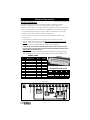
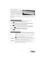
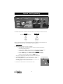
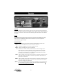
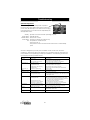
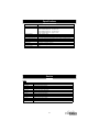
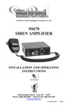
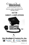
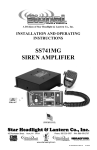
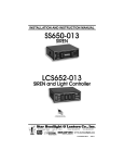
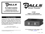
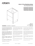
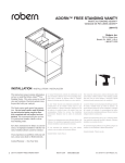
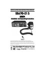
INSTALLATION AND INSTRUCTION MANUAL
SS670SS670-013
SIREN
Installation and Operating Instructions
NOTICE
Due to continuous product improvements, we must reserve the right to change any
specifications and information, contained in this manual at any time without notice. Signal
Vehicle Products and/or the manufacturer make no warranty of any kind with regard to this
manual, including, but not limited to, the implied warranties of merchantability and fitness for a
particular purpose. Signal Vehicle Products and/or the manufacturer shall not be liable for errors
contained herein or for incidental or consequential damages in connection with the furnishing,
performance, or use of this manual.
PLITSTR332 REV. B
9/27/13
Installation Information
MODEL: SS670-013
Serial #:
PURCHASE DATE:
INSTALLATION DATE:
INSTALLER:
DEALER:
Model and serial number located on bottom of unit
TABLE OF CONTENTS
GENERAL DESCRIPTION
1
INSTALLATION NOTES
1
MOUNTING TIPS
1
ELECTRICAL CONNECTIONS
2-3
Wiring Guide
Wiring Diagram
Mandatory Connections
Optional Connections
2
2
3
3
OPTIONAL TONE PROGRAMMING
4-5
OPERATION
6-7
Power
Selector Switch
MAN Button
HORN Button
PA Volume
Radio Volume
Microphone
Auxiliary Input
6
6
7
7
7
7
7
7
TROUBLESHOOTING
8
SPECIFICATIONS
8
SERVICE
9-10
Parts
Warranty
9
10
-i-
General Description
The SS670 Siren Amplifier is a premium 100W unit designed for single 100W speaker
use. The primary operating modes are Phaser, Yelp, Wail, Hands Free, Manual, Alert,
and Radio. A Noise Canceling PA Override and push-button Horn Override are
available in all modes. A manual push-button is provided for push-on/push-off tone
toggle operation in the Phaser, Yelp, and Wail modes. It also allows manual siren
control in the Manual or Alert modes. Any siren tone can be re-programmed to a
more desired tone. Another feature allows cycling through Wail, Yelp, Phaser, and
Standby by providing a signal to the horn ring auxiliary wire when the function switch
is in the Hands Free (HF) position. Radio and PA volume controls are provided on
the front panel. The front panel is backlighted with LED's for night visibility. This
compact unit utilizes short circuit, high voltage, low voltage, and reverse polarity
protection systems for maximum service life.
Installation Notes
Proper installation of the unit is essential for years of safe, reliable operation. Please
read all instruction before installing the unit. Failure to follow these instructions can
cause serious damage to the unit or vehicle and may void warranties.
Qualifications - The installer must have a firm knowledge of basic electricity, vehicle
electrical systems and emergency equipment.
Keep These Instructions - Keep these instructions in the vehicle or other safe place
for future reference. Advise the vehicle operator of the location.
Unpacking - Inspect contents for shipping damage. If found, alert carrier
immediately. Contents should include unit with microphone, mounting bracket w/
hardware, microphone bracket with 2 screws, wiring connector, and these
instructions. Contact your supplier immediately if any components are missing.
Mounting Tips
• Mount in a location with adequate ventilation to prevent overheating.
• Devices should be mounted only in locations listed in SAE standard J1849.
• Controls should be placed within convenient reach of the driver.
• Assure clearances before drilling in vehicle.
• Sound levels produced by attached speakers can cause permanent hearing loss.
• Never operate this unit without adequate hearing protection for you and others
in the area. (OSHA 1910.95)
• Consider wire routing and access to connections.
• Install mounting bracket to vehicle using 1/4" hardware (not supplied).
-1-
Electrical Connections
Wire Size and Termination
Electrical connections to this unit are made through the green 12-terminal
connector located in the rear of the unit (See below - Part # CPSS-153).
Examine the charts below to determine the proper gauge of the wire to use. Please
review the following recommendations when making your electrical connections:
• Use only high quality crimp connectors. Make sure all connections are tight.
• Minimize the number of splices to reduce voltage drop.
• Route wiring to prevent wear, overheating, and interference with air bag
deployment.
• Use grommets and sealant when passing through compartment walls.
• Ground connections should be made directly to the negative of the vehicle
battery. Where not possible, only connect to substantial chassis components.
• Install and check all wiring before connection to vehicle battery.
• CAUTION: All wires should be rated for at least 125% of their maximum current
load. All wires connected to the positive terminal of the battery should be fused
at the battery for their rated load.
• Review the charts below that indicate the recommended wire gauge, based
upon the length of the wire run and the current that will pass through the wire.
WIRING GUIDE
Terminal
1
2
3
4
5
6
7
8
9
10
11
12
CPSS-153
Typical
Color
Power (+12VDC)
Red
Power (+12VDC)
Red
Ground
Black
Ground
Black
Speaker 1
Brown
Speaker 2
Brown
AUX In
Green
Logic Power
Orange
Radio Repeat
Blue
Radio Repeat
Blue
Backlighting Power Yellow
N/A
Description
Typical
Current
10A
10A
10A
10A
4A
4A
3A
0.06A
0.1A
0.1A
0.1A
RECOMMENDED WIRE GAUGE
Current
10'
20'
25'
< 2.0A
2.0-4.0A
4.1-5.5A
22 AWG
18 AWG
18 AWG
18 AWG
16 AWG
16 AWG
18 AWG
16 AWG
14 AWG
5.6-8.0A
8.1-12.0A
16 AWG
16 AWG
14 AWG
12 AWG
14 AWG
12 AWG
(SIREN TOP)
WARNING: ENSURE CONNECTOR IS FULLY INSERTED & SCREWS LOCKED
12
11
10
9
7
6
5
3
2
20A
Fuse
- 12V +
BATTERY
-2-
Ignition Switch
SPEAKER
100W
1
Power
Factory
Horn
Relay
4
Ground
AUX In
Logic Power
Backlighting Power
NOT USED
2 Way
Radio
Speaker
8
SS670
TONE
SELECT
(Electrical Connections CONT’D)
For ease of installation, you can remove
the green connector from the siren while
connecting your wires. Please note that
when referencing terminal numbers using
the wiring diagram on the previous page,
the screw heads face DOWN, as pictured
to the right.
Connections to the terminal block are summarized both in the chart and in the
wiring diagram on the previous page. For more detailed information, review the
section below.
Mandatory Electrical Connections
Ground - Connect terminals 3 & 4 to the negative terminal of the battery.
(You MUST connect both of these terminals!!)
Power - Connect terminals 1 & 2 to a 10-16VDC ignition switched power source
capable of supplying 20A. Be sure to use minimum size #14 AWG wire.
(You MUST connect both of these terminals!!)
Logic Power - Connect terminal 8 to a 10-16VDC ignition switched power source.
(You MUST connect this terminal or the unit will not function!!)
Speaker - Connect terminals 5 and 6 to your siren speaker.
(You MUST connect both of these terminals!!)
Optional Electrical Connections
AUX IN - This terminal is typically connected to the steering wheel horn relay.
It allows for several functions including siren operation in HF mode
(see page 6), Air Horn activation, or Manual “step up” function (see
page 5).
If you will be using any of these features, connect terminal 7 to the
output of your steering wheel relay.
(Only compatible with positive-side switched horn relays)
Radio Repeat - If you would like the ability to re-broadcast your two-way radio over
your siren speaker, connect terminals 9 & 10 to the two-way radio
speaker or output connector of the two-way radio.
Backlighting - Connect terminal 11 to the dash lights, ignition switched power, or
other switched 10-16VDC power source. This controls the
backlighting for the face of the siren.
-3-
Optional Tone Programming
The SS670 will produce 7 different tones/sounds by activating its various functions:
Function
Phaser Step Up (PHSR+MAN)
PHSR
YELP
WAIL
MAN
HORN
AUX
Default Tone
Two-Tone
Phaser
Yelp
Wail
Ramp Up
Air Horn
Air Horn
Each of these functions can be reprogrammed for a different tone, if desired. To
change the sounds for any of the functions, proceed below.
1. Power the unit up.
2. Activate the function you wish to change.
• For PHSR, WAIL, and YELP functions, rotate the selector knob into
the corresponding position.
• For the MAN, HORN, or AUX functions, rotate the selector knob into
the MANUAL or ALERT position, then press and hold the MAN
button, HORN button, or steering wheel horn, respectively.
• For the Phaser Step Up function, rotate the knob into the PHSR
position, then press and release the MAN button.
The tone currently programmed for that function will sound.
3. The Tone Program button can be found on the rear of the
siren. Using a paper clip, press and release it to cycle
through the list of optional tones. Review the chart on the
following page for a list of optional tones.
4. De-activate the function to save the new tone.
-4-
Tone Program Button
(Installer Selectable Options CONT’D)
Optional Tones
Tones For WAIL, YELP, and PHSR,
Tones For MAN Button and AUX Wire
and Phaser Step-Up Function
1 STANDARD AIR HORN (AUX default)
1 WAIL (Wail default) §, *, †
2 LOW FREQUENCY AIR HORN
2 YELP (Yelp default) §, *
3 RAPID AIR HORN
3 PHASER (PHSR default)
4 AIR HORN II
4 TWO-TONE (PHSR Step Up default)
5 MECHANICAL WAIL (FIRE ENGINE) † 5 DOUBLE POST POP AIR HORN
6 SINGLE AIR HORN
6 MAX YELP §, *
7 SINGLE QUICK AIR HORN
7 HOOT
8 TWO TONE AIR HORN
8 RAPID HOOT
9 MANUAL (MAN default) *
9 AIR HORN & YELP
10 MECHANICAL MANUAL (FIRE ENGINE)
10 GHOST
11 RAPID GHOST
►►►► System Reset ◄◄◄◄
12 SINGLE AIR HORN
13 SINGLE QUICK
14 DOUBLE POST POP AIR HORN
15 TWO TONE AIR HORN
16 STANDARD AIR HORN
17 CONTINUOUS TONE
18 CONTINUOUS BEEP
§ = SAE approved
* = California Title 13 approved
† = See below
Tones for Horn Button
1 STANDARD AIR HORN (default)
2 LOW FREQUENCY AIR HORN
3 RAPID AIR HORN
4 AIR HORN II
5 DOUBLE POST POP AIR HORN
6 SINGLE AIR HORN
7 SINGLE QUICK AIR HORN
8 TWO TONE AIR HORN
If you would like to reset ALL of the siren programming
options to their defaults, activate any tone and press
the Program button for six (9) seconds. The LED will
flash once, then twice, then three times, and all siren
tones will stop.
Wind Down or Hard Stop Option
By default, the Wail tones indicated by the “†” above will “wind down” when they
are de-activated. If you prefer to have them immediately stop (i.e. hard stop), hold
the Program Button for 3 seconds (until the LED flashes once). This will change it to a
hard stop. Repeat to change back to the wind down option.
Tone Disable Option
Some municipalities may ban the use of specific tones, such as the Phaser tone. The
Phaser Disable jumper option (found in our previous versions of the SS700) has been
replaced with the Optional Tone Programming feature described on the previous
page. This will allow you to reprogram the PHSR default tone from Phaser to any of
the other tones listed. This new feature expands the former option (that was
previously limited only to disabling the Phaser tone) to the ability to replacing ANY of
the tones that may not be permitted (or desired).
Auxiliary-Manual Function Option
By default, when the siren is in PHSR, YELP, or WAIL modes, and the AUX function is
activated (typically by the steering wheel horn relay), the siren will produce the
standard Air Horn Tone (#1 in the chart above) and temporarily override the siren
tone. If you would rather have the AUX function (i.e. steering wheel horn) mimic the
MAN button (see MAN button functions on page 7), then you should program the
AUX function for tone #9 (Manual) or #10 (Mechanical Manual).
-5-
Operation
General
This unit is designed for easy operation under the stress associated with high-speed
pursuit. Most siren functions are accessible with one simple motion without repetitive
activation of switches or automatic timed switching that can interfere with desired
operation.
Power
The Power switch is located on in the center of the front panel. While in the OFF
position none of the siren functions will work. The position of this switch does NOT
affect the siren backlighting, which remains lit whenever power is applied to
terminal 8 (see pages 2 and 3).
Selector Switch
The rotary selector switch controls the primary operating function of the siren.
PHSR - Ultra-fast changing tone used for maximum attention.
YELP - A rapidly changing tone used in congested areas.
WAIL - A slower changing tone used on highways.
HF - Hands Free - A silent standby mode also known as Horn Ring Cycler.
Allows the user to cycle through the tones programmed for the WAIL,
YELP, PHSR, and OFF by repeatedly pressing the horn or other switch
connected to the AUX input. Changing the rotary knob to any other
mode will resume normal siren operation.
MAN - A silent standby mode that allows push-button Manual, push-button Horn,
and Public Address operation. The siren output winds down when the
MAN button is released.
ALERT - A silent standby mode that allows push-button Manual, push-button Horn
and Public Address operation. The siren output terminates immediately
when the MAN button is released.
RADIO - Also known as Radio Repeat, this function amplifies a radio speaker input
for re-broadcast outside the vehicle. The PA remains functional, but no
siren tones are available in this position.
-6-
(Operation CONT’D)
The front panel of the SS670 contains two
momentary push-button switches for the Manual
function and the Air Horn.
MAN Button
Rotary Switch
Position
MAN or HF
ALERT
PHSR/YELP/WAIL
Function When MAN Pressed
Produces a rising siren tone while being pressed. The siren
output “winds down” when the MAN button is released.
Also produces a rising tone, but the siren output immediately
stops when the button is released.
The MAN button will “step” the siren up to the tone programmed
for the next function:
(WAILYELPPHSRPhaser Step Up)
These quicker tones are used to momentarily alert motorists at
intersections and very highly congested areas. Pressing the
MAN button once changes to the next faster tone. Pressing the
MAN button again, reverts the siren back to the original tone.
HORN Button
Pressing the HORN button provides a simulated air-horn tone while pressed. This can
be used to either replace or to supplement the normal vehicle horn and is useful at
intersections. This tone will override all other siren tones. See pages 4-5 for
programming optional Air Horn tones.
PA VOL.
The PA knob is located in the upper right hand corner of the
front face. It provides you the ability to adjust the public
address volume. It should be set when the vehicle is parked.
Typically you should set the PA volume to the maximum
possible level with no feedback (squeal).
Radio Volume
The radio repeat volume (Radio) control is recessed in the upper
left hand corner of the front face. This should be set when the
vehicle is parked. First set the volume level of the vehicle's twoway radio to its normal operating volume. Adjust the siren's
rotary selector switch into the RADIO position. Insert a small, flat
blade screwdriver into the RADIO volume adjustment port. Turn
in a clockwise direction to increase the sound level.
Microphone
The attached microphone is used for public address
operation and overrides any siren tone when its pushto-talk (button on the side) is pressed.
Auxiliary Input
During installation an auxiliary input may be connected to the vehicle horn ring or
other switching device (see page 3). It provides the same operation as pressing the
HORN button or can be programmed to function like the MAN button (see page 5).
-7-
Troubleshooting
Speaker Diagnostics
There is a diagnostic LED shaped like a speaker
located in the upper right hand corner of the front
panel. This LED will only turn on while a tone is trying
to be generated. It can be used to help identify the
siren/speaker status.
Steady Single Flash Double Flash Quad Flash Off -
Speaker is connected and operating properly.
Standby Mode
Short/Over Current
Improper Voltage (too high or low)
No speaker is connected, or
The siren is Off, or
The speaker or wire connection has come loose or is electrically
open
This unit is designed to provide years of reliable service under even the worst
conditions. Many times there may appear to be a problem with the unit when the
true problem is in the speaker(s) or improper installation. The following chart shows
typical symptoms and possible causes.
Symptom
No power
No siren tone - PA
works
No siren tone - No
sound
No PA
Possible Cause
Connector loose
Siren 20A fuse blown
Loose connection at power source
High voltage protection
Low voltage protection
Microphone button stuck
Park Kill polarity option set wrong
Park Kill activated
Bad speaker or speaker wiring
PA volume not set properly
Distorted siren sound
Speaker assembly loose
Intermittent Aux. Input connection
Low or high vehicle voltage
Intermittent siren tone
High voltage protection
Low voltage protection
Microphone button activation
Circuit breaker in supply connection
Shorted speaker or speaker wire
Horn function or
Manual or Horn push buttons stuck
Manual or Phaser stuck Aux. Input improperly connected
on
Aux. Input Polarity Option set wrong
No Radio
Unit not connected to radio
Radio volume too low
Wrong siren tone
Siren tones programmed incorrectly?
Check
Check connector
Is power hooked up backwards? Positive ground vehicle?
Is an external fuse or circuit breaker used?
Are the negative leads connected to a good ground?
The input voltage must be less than 16 volts.
The input must be greater than 10V with the siren turned on.
Does microphone button release properly?
Is the PK jumper option properly configured?
Does the siren work when Park Kill input is disconnected?
Check for a short.
Check for an open.
Have you tried turning the PA volume control?
Is the speaker bell or tip loose?
Is the Aux. Input connected properly to horn relay?
Input voltage must be between 10 & 16 volts while siren is on and
drawing full current.
Is the vehicle voltage regulator working properly?
Is the connector tight on the back of the unit? Is there a loose
connection on a power lead? The input must be greater than
10V with the siren on and drawing full current.
Is something lying on the microphone?
Is a circuit breaker used with at least a 50A rating?
Does the speaker have water damage, or is a wire pinched?
Does the switch return fully when released?
Is the Aux. Input used and wired properly?
Is the AUX polarity jumper option properly configured?
Is the radio connected properly to the unit?
Can you hear the radio in the vehicle?
Adjust the Radio volume control
Re-program tones/Use System Reset (page 5)
-8-
Specifications
Input Voltage
Input Current
Standby Current
Audio Frequency
Audio Output Power
Siren Frequency
High Voltage Protection
Short Circuit Current
Operating Temperature
Connections
Size
Shipping Weight
10 - 16 VDC (negative ground)
8.0 Amps @ 13.6 VDC (single 100W speaker)
Switch Off/Backlighting Off - Less than 4 mA
Switch On/Backlighting Off - Less than 7 mA
Switch Off/Backlighting On - Less than 18 mA
Switch On/Backlighting On - Approx. 22 mA
200Hz - 10 kHz + 3db
105 Watts RMS MAX
675Hz - 1633Hz
16 - 18 VDC will cause siren output to cease, resumes at normal voltage
30 AMPS (supply circuit must be capable of supplying this)
-15° F to +140°F
Detachable 12-terminal connector
6" Wide, 4.7" Deep, 2" High
6 lbs.
Service
Parts
Part
S30235-15
S30234-15
SWH-152
P30069-38
P30056-16
P30028-27
P30232-1
P30208-10
P30032-8
P30239-1
P30147-44
P30050-14
Description
Siren Top Cover
Siren Bottom Mounting Plate
Optional Wiring Harness
Microphone Bracket with Screws
1/4-20 x 3/8" Hex Locking Bolt
15 Amp Automotive Fuse
Noise Cancelling Microphone
Microphone Strain Relief
TIP36CPowerTransistor
Rotary Selector Switch Knob
Mounting Bracket
Case Screws
-9-
ONE YEAR LIMITED WARRANTY
The manufacturer warrants each new product against factory defects in
material and workmanship for one year after the date of purchase. The
owner will be responsible for returning to the Service Center any
defective item(s) with the transportation costs prepaid. The manufacturer
will, without charge, repair or replace at its option, products, or part(s),
which its inspection determines to be defective.
Repaired or
replacement item(s) will be returned to the purchaser with transportation
costs prepaid from the service point. A copy of the purchaser's receipt
must be returned with the defective item(s) in order to qualify for the
warranty coverage. Exclusions from this warranty include, but are not
limited to, bulbs, strobe tubes, domes, and/or the finish. This warranty shall
not apply to any light, which has been altered, such that in the
manufacturer's judgment, the performance or reliability has been
affected, or if any damage has resulted from abnormal use or service.
There are no warranties expressed or implied (including any warranty of
merchantability or fitness), which extend this warranty period. The loss of
use of the product, loss of time, inconvenience, commercial loss or
consequential damages, including costs of any labor, are not covered.
The manufacturer reserves the right to change the design of the product
without assuming any obligation to modify any product previously
manufactured.
This warranty gives you specific legal rights. You might also have
additional rights that may vary from state to state. Some states do not
allow limitations on how long an implied warranty lasts. Some states do
not allow the exclusion or limitation of incidental or consequential
damages. Therefore, the above limitation(s) or exclusion(s) may not
apply to you.
If you have any questions concerning this or any other product, please contact
our Customer Service Department at (585) 226-9787.
If a product must be returned for any reason, please contact our
Customer Service Department to obtain a Returned Materials Authorization
number (RMA #) before you ship the product back.
Please write the RMA # clearly on the package near the mailing label.