1
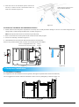
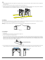
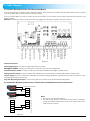
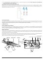
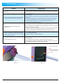
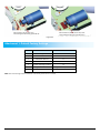
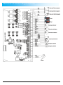
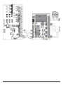
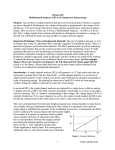
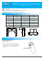
TS2000 Series Vertical Tripod Turnstile User Manual
Version: 1.0
TS2000:
TS2011:
TS2022:
Time: 2014-3
Tripod Turnstile
Tripod Turnstile with Controller and RFID Reader
Tripod Turnstile with Controller and Fingerprint Reader with RFID function
Please read this document carefully before installation and using the device.
1. Technical Specifications
Input Voltage
AC 220V / 110V,
50Hz / 60Hz
Max. Tolerance of Arms
Center: 80 kg
End: 40 kg
Rated Power
60 W
Ingress Protection Degree
IP54
Operating Environment
Indoor and Outdoor
Arm Length (mm)
500
Operating Temperature
-28ºC ~ 60ºC
Net Weight
46kg
Operating Humidity
5% ~ 85%
Gross Weight
54kg
Flow Rate
Input Control Signal
25~48 passages / minute Dimension(mm) Figure 1
Dry contact
1110
Package Size (mm)
L = 1110, W = 260, H = 980
L = 1200, W = 380, H = 1080
260
500
740
500
980
980
260
1110
Figure 1
2. Arm Installation and Equipment Testing
2.1 Arm Installation Method
Installation procedure
1. Open the glue and apply in the square openings of
the arms as well as the four countersunk screws, as
shown in figure 2-1. (This is to prevent screws from
getting loose due to vibration after being used for a
long time.)
This opening shall be
applied with glue evenly.
Figure 2-1
1
2. Insert the arms to the connection points, and use the
Hex key to fasten the four countersunk screws on
each arm, as shown in figure 2-2.
Tighten the four screws on each
arm in clockwise direction.
Figure 2-2
2.2 Power-on Test Before the Installation of Device
1. Please make sure that the power requirements are strictly met to avoid permanent damage to the unit. You could change the input
voltage 110V or 220V through the DIP switch, as shown in figure 2-3.
Note: The tripod turnstile must be connected to ground (earth).
2. Power on and wait 30s for the tripod turnstile to finish the self-check program.
3. Lift the arms manually, as shown in figure 2-4.
4. Check whether the tripod turnstile and the LED indicators work properly.
If there is any problem, please refer to section 4.2 or kindly contact the supplier.
There is a voltage DIP switch in the
side direction of this power supply.
Wiring
terminal
220V
110
Lift upwards
220
Label
DIP switch
110V
220V
110V
Figure 2-3
Figure 2-4
3. Equipment Installation
3.1 Installation Conditions
The equipment must be installed on concrete ground, ensuring that expansion bolts can be secured firmly.
You are suggested to install an assistant framework or fence to form a passageway, as shown in figure 3-1.
>100
<80
<80
500
500
260
980
Assistant
framework
260
Figure 3-1
2
Note:
1. When installing the tripod turnstile against the wall, please reserve at least 100 mm space in order to open the cover for adjustment
and maintenance.
2. The space at the end of the arm shall not be greater than 80 mm (see figure 3-1).
3. Setting a warning line for card swiping (see figure 3-2). A warning line is suggested to prompt users to swipe cards in a distance,
which would greatly reduce the probability of equipment failure caused by improper operations.
Warning line for card swiping
Warning line for card swiping
Warning line for card swiping
Warning line for card swiping
Figure 3-2
3.2 Cabling
There are inlets in the bottom plate for cabling, as shown in figure 3-3. Power supply and communication wire should go through the
inlet. Cable protection covers are suggested to use if it is surface mounted.
Warning: The tripod turnstile must be connected to Ground (earth), there is wiring interface in the power switch.
945.00mm
176.00mm
Figure 3-3
3.3 Installation
1. Drilling holes
Drill holes based on the locations of the holes shown in figure 3-3.
2. Fix the mounting plate to its original position
Placing the mounting plate properly and apply screw securing glue on the surface and the threads of the expansion bolts, install four
expansion bolts to secure the mounting plate, and use a horizontal ruler to test the levelness of the mounting plate. If the mounting
plate is not level, adjust it by the gaskets provided. Note that all the four expansion bolts must be installed properly, and two
expansion bolts on each column, as shown in figure 3-4.
Screw securing glue shall
be applied on the threads.
Figure 3-4
3. Put the turnstile on the mounting plate and tighten the screws. Apply screw securing glue before use and put gaskets on the screws
to adjust the direction of the turnstile. If the tripod turnstile is not level, you can place gaskets to adjust, as shown in figure 3-5.
Installation levelness
Installation levelness
Figure 3-5
3
4. Cable Diagram
4.1 Function Description of the Turnstile Control Board
If you are using TS2011 or TS2022, all the connections between access control and turnstile control board are done in factory. Just plug
in communication cable to access controller and do the setting.
If you are using TS2000, you need to connect access control system to the turnstile control board, please check the content in this
chapter carefully.
Warning: The third party access control system lock relay trigger time should be 1 second or less than 1 second.
Input end of
turnstile opening
Input end of droparm electromagnet
Output end of
counter signal
Passing Indicator
Input
Direction Indicator
Input
Direction Indicator
Input
Optocoupler
Power Output
Optocoupler Signal
Input
Emergency Switch
opening signal Input
RS485 (Reserved)
Power supply input
Figure 4-1
Interface description:
Opening Signal Input: to receive relay signal and open the turnstile.
Emergency Switch: to keep the turnstile open in case there are fire or other emergencies.
Direction Indicator Output: to connect a LED screen and indicate whether this passage is allowed to pass.
Passing Indicator Output: to connect a LED screen and indicate if user verification is successful and whether it is able to pass.
Counter Output: to connect a LED screen and display the number of people passed that is generated by the push of tripod arms, each
completed push means pass one time.
Drop Arm Electromagnet Output: to control the tripod arms manually rise up and automatically drop down.
4.2 Connection Diagram of the Access Control Panel or Standalone Access Control Device
Turnstile Control Board
NO2
COM1
Enter
NO1
Access Control
K1
GND
GND
BUT
K2
NO1
GND
COM1
NC1
Opening Signal Input Port
SEN
Counter Output Port
COM2
Exit
Notes:
1. The Counter is an optional accessory.
2. The lock driving duration of the access control panel or standalone
access control device needs to be set to 1s or 0s, and the door sensor
needs to be set to “None”.
Figure 4-2
4
4.3 Parameter Configuration
Function description of the DIP switch
Down position
indicates value 1.
Up position
indicates value 0.
Figure 4-3
Pin
1
Function Setting
2
3
4
Opening Duration
5
6
Direction Indicator
Memory Function
4.3.1 Setting the Turnstile Opening Duration
Opening duration refers to the period of time from opening to closing once the turnstile receives an open signal.
In the DIP switch, number 1, 2, and 3 are used for duration setting. It can be set to different values from 5s to 60s according to the
following chart.
Duration
Bit Setting
Duration
Bit Setting
5s
000
30s
001
10s
100
40s
101
15s
010
50s
011
20s
110
60s
111
Note: The turnstile opening duration is set to 5s by default.
4.3.2 Direction Indicator
It is to indicate whether the passage allows people to pass. The green arrow means passing is allowed while the red "X" means passing is
prohibited. The indicator status can be set through number 4 and 5 in the DIP switch. The description of the bit settings are as follows:
00 = One-way traffic. Green indicator indicates that passing is allowed while red indicator indicates that passing is prohibited.
10 = One-way traffic. Green indicator indicates that passing is allowed while red indicator indicates that passing is prohibited.
01 = Passing is allowed in both directions.
4.3.3 Memory Function
With the memory function, the turnstile could remember at most 20 swipes of one card at one time and allows up to 20 visitors to pass
so they don’t have to swipe card each time, this function can be enabled or disabled through number 6 in the DIP switch. The description
of the bit settings are as follows:
ON (up): indicates that the memory function is enabled.
OFF (down): indicates that the memory function is disabled.
5. Equipment Precautions and Maintenance
5.1 Precaution
1. It is recommended to purchase optional accessories to use in outdoor environment.
(1) It shall install optional cooling fans for the equipment if the working temperature is often above 50 ºC.
(2) It is equivalent to IP54 waterproof under proper installation. However, it cannot work in the region that may suffer typhoon.
(3) If the temperature is -30ºC, a heating plate is suggested to install. It might need multiple times to power on while getting hot
automatically through the self-check program.
(4) The service life of this equipment may be shortened if it works outdoors in coastal areas or a region prone to acid rain.
2. If the power and signal cables are connected properly, this equipment can be immersed in water of 250 mm deep, but it must not be
powered on for operating when it is immersed in water.
3. It is highly recommended that a card swiping warning line to set for prompting passers-by to swipe cards properly and a reasonable
passage width shall be set to prevent passers-by from squeezing in illegally.
5
4. It is recommended that a warning sign is placed at a conspicuous position, and prompt: "Please swipe your card outside the
warning line and pass in order. Thank you!”
The maximum tolerance of the tripod turnstile's arms
Please note that the maximum stress tolerance at the center of the arm is 80kg and at the ends of the arm is 40kg (See figure 5-1).When
the impact force on the tripod turnstile reaches the designed limit, the arms break down first to ensure that the whole equipment is not
damaged and the passer-by is not injured.
Maximum stress
tolerance: 40 kg
Maximum stress
tolerance: 80 kg
Figure 5-1
In case of emergencies
This equipment is designed to drop down arms automatically if there is power failure thus make the passage being open to the public.
And there is interface in the turnstile board to connect an emergency switch which would make the tripod turnstile keep open in case of
emergencies. Note after power restoration, wait for more than 6s and then lift the arms manually.
5.2 Maintenance
Forming maintenance consciousness
The tripod turnstile needs to be maintained regularly and repaired once it is damaged. It is recommended that warning signs being
placed at conspicuous positions for prompting passers-by to pass in a proper way and in good order. Reasonable maintenance
consciousness helps to guarantee long-term usage of the tripod turnstile.
Regular maintenance
Cleaning and protection liquid dedicated for stainless steel are recommended to wipe the outer shell of the equipment regularly. The
tripod turnstile used outdoors or in an environment with lots of dust must be maintained once a year at least. Note regular maintenance
should be performed after power off the equipment.
The damping accumulator is used to adjust the tripod turnstile's elasticity and return speed. You can rotate it in clockwise direction to
enhance and in anticlockwise direction to weaken the elasticity and return speed of the tripod turnstile. See figure 5-2.
Figure 5-3 shows the mechanical and electrical structure of this equipment.
Drop-arm
electromagnet
Optical-coupling
blanking disc
Damping
accumulator
Turnstile-opening
Trilobed wheel Lock rod electromagnet
Turnstile-opening
electromagnet
Lock rod
Figure 5-2
Figure 5-3
6
6. Troubleshooting
Symptom
The indicator is not lighted when the equipment is
powered on.
The arms of the tripod turnstile cannot be lifted
manually after the equipment is powered on.
The tripod turnstile does not open after
authentication.
The passing is not smooth after the turnstile is
opened, it encounters resistance when pushing
the arms, and the arms cannot return to the home
position after they rotate.
The arms drop during the use.
Troubleshooting
It may be caused by the power supply or circuit.
Check whether the connection cable and power cable between are damaged,
or the wiring is loose.
It may be caused by the problem of relative components or drop-arm
electromagnet.
1. Check whether the stop base and turn plate withstands each other, as shown in
figure 6-1.
2. Check whether the drop-arm electromagnet is operating. Remove the upper
cover of the framework, use a hex key to remove the cover of the control
module (as shown in figure 6-2), and check the work status of the
electromagnet, as shown in figure 6-3.
It may be caused by lack of permission or a circuit problem.
1. Check whether the user has the permission to open the turnstile.
2. Use a multimeter to check whether the NO and COM ports of the access control
system has a relay signal output.
3. Short-circuit the ports "K1, GND" and "K2, GND", if the turnstile is successfully
opened, it would be the controller problem. In this case, please refer to
Attachment 2 to check the cable connection of the controller.
It is caused by the damper.
Adjust the damper, as shown in figure 5-2.
It may be caused by the problem of relative components or drop-arm
electromagnet.
1. Check whether there is any gap at the position shown in figure 6-1.
2. Check whether the drop-arm electromagnet is totally closed. If not, power off
the equipment and power on it again 2 minutes later.
Control module cover
Screw for securing the
control module cover
Figure 6-1
Figure 6-2
7
Normal status of the drop-arm
electromagnet after being powered off
Normal status (closed) of the drop-arm
electromagnet after being powered on
Figure 6-3
Attachment 1- Default Factory Settings
No.
Function
Default
1
Lock Driving Duration
5s
2
Door Sensor
None
3
Verification Interval
1s
4
Controller Communication
TCP/IP: 192.168.1.201
5
Turnstile Opening Duration
5s
6
Passing Direction Indicator
Passing is allowed (Green Arrow)
7
Memory Function
Disabled
Note: The Lock Driving Duration is default 5 seconds, please set to 1 second.
8
Attachment 2- Connection Diagram Overview
9
10