1
Synchronous Link
Control (SLC)
Programmer’s Guide
DC 900-1564A
Simpact, Inc.
9210 Sky Park Court
San Diego, CA 92123
August 1998
Simpact, Inc.
9210 Sky Park Court
San Diego, CA 92123
(619) 565-1865
Synchronous Link Control (SLC) Programmer’s Guide
© 1998 Simpact, Inc. All rights reserved
Printed in the United States of America
This document can change without notice. Simpact, Inc. accepts no liability for any errors this
document might contain.
Freeway is a registered trademark of Simpact, Inc.
All other trademarks and trade names are the properties of their respective holders.
Cross References:
(keep this hidden)
SLC
slc
???
Contents
List of Figures
7
List of Tables
9
Preface
11
1
15
Introduction
1.1
1.2
Protocol Overview . . . . . . . . . . . . . . .
Supported Hardware. . . . . . . . . . . . . .
1.2.1 Freeway Server . . . . . . . . . . . . . .
1.2.2 Embedded ICPs . . . . . . . . . . . . .
1.2.2.1 Windows NT (Intel or Alpha) . . .
1.2.2.2 OpenVMS. . . . . . . . . . . . . .
1.2.2.3 Digital UNIX . . . . . . . . . . . .
1.3 Available Programming Interfaces . . . . . .
1.3.1 Data Link Interface (DLI) . . . . . . . .
1.3.2 Driver Interface. . . . . . . . . . . . . .
1.3.3 Socket Interface (Freeway Server Only) .
2
.
.
.
.
.
.
.
.
.
.
.
.
.
.
.
.
.
.
.
.
.
.
.
.
.
.
.
.
.
.
.
.
.
.
.
.
.
.
.
.
.
.
.
.
.
.
.
.
.
.
.
.
.
.
.
.
.
.
.
.
.
.
.
.
.
.
.
.
.
.
.
.
.
.
.
.
.
.
.
.
.
.
.
.
.
.
.
.
.
.
.
.
.
.
.
.
.
.
.
.
.
.
.
.
.
.
.
.
.
.
.
.
.
.
.
.
.
.
.
.
.
.
.
.
.
.
.
.
.
.
.
.
.
.
.
.
.
.
.
.
.
.
.
.
.
.
.
.
.
.
.
.
.
.
.
.
.
.
.
.
.
.
.
.
.
.
.
.
.
.
.
.
.
.
.
.
.
.
.
.
.
.
.
.
.
.
.
.
.
.
.
.
.
.
.
.
.
.
SLC Protocol Theory of Operation
2.1
2.2
SLC Envelope Service . . . . . .
SLC Protocol Service. . . . . . .
2.2.1 Network-level Support . . .
2.2.2 Message Blocking Support .
2.2.3 Multi-channel Support. . .
2.2.4 Retransmission Support . .
2.2.5 Safe Store Support . . . . .
DC 900-1564A
15
15
16
16
17
17
18
18
18
19
19
21
.
.
.
.
.
.
.
.
.
.
.
.
.
.
.
.
.
.
.
.
.
.
.
.
.
.
.
.
.
.
.
.
.
.
.
.
.
.
.
.
.
.
.
.
.
.
.
.
.
.
.
.
.
.
.
.
.
.
.
.
.
.
.
.
.
.
.
.
.
.
.
.
.
.
.
.
.
.
.
.
.
.
.
.
.
.
.
.
.
.
.
.
.
.
.
.
.
.
.
.
.
.
.
.
.
.
.
.
.
.
.
.
.
.
.
.
.
.
.
.
.
.
.
.
.
.
.
.
.
.
.
.
.
.
.
.
.
.
.
.
.
.
.
.
.
.
.
.
.
.
.
.
.
.
.
.
.
.
.
.
.
.
.
.
.
.
.
.
.
.
.
.
.
.
.
21
21
22
22
22
22
23
3
Synchronous Link Control (SLC) Programmer’s Guide
2.2.6
3
Flow Control Support . . . . . . . . . . . . . . . . . . . . . . . . . . . .
Typical Sequence of Operations
3.1
3.2
3.3
3.4
3.5
3.6
3.7
3.8
3.9
3.10
3.11
3.12
3.13
3.14
4
Initialization . . . . . . . . . .
Attaching a Link . . . . . . . .
Configuring an Attached Link .
Binding an Attached Link . . .
Sending an SLC Message . . . .
Receiving an SLC Message . . .
Sending an SLC Block . . . . .
Receiving an SLC Block . . . .
Exerting Operator Control . . .
Detecting Network Control . .
Unbinding a Link . . . . . . . .
Reading Reports . . . . . . . .
Detaching a Link . . . . . . . .
Termination. . . . . . . . . . .
25
.
.
.
.
.
.
.
.
.
.
.
.
.
.
Access Category. . . . . . . . . .
4.1.1 Attach . . . . . . . . . . . .
4.1.2 Detach . . . . . . . . . . . .
4.2 Link Category. . . . . . . . . . .
4.2.1 Bind . . . . . . . . . . . . .
4.2.2 Unbind . . . . . . . . . . .
4.2.3 Configure Link . . . . . . .
4.2.4 Control . . . . . . . . . . .
4.3 Data Category. . . . . . . . . . .
4.3.1 Safe Store Acknowledgment
4.3.2 Normal Data . . . . . . . .
4.3.3 Priority Data . . . . . . . .
4.3.4 Transparent Data . . . . . .
4.4 Report Category . . . . . . . . .
4.4.1 Get Buffer Report . . . . . .
4.4.2 Get Link Configuration. . .
4.4.3 Get Software Version . . . .
4
.
.
.
.
.
.
.
.
.
.
.
.
.
.
.
.
.
.
.
.
.
.
.
.
.
.
.
.
.
.
.
.
.
.
.
.
.
.
.
.
.
.
.
.
.
.
.
.
.
.
.
.
.
.
.
.
.
.
.
.
.
.
.
.
.
.
.
.
.
.
.
.
.
.
.
.
.
.
.
.
.
.
.
.
.
.
.
.
.
.
.
.
.
.
.
.
.
.
.
.
.
.
.
.
.
.
.
.
.
.
.
.
.
.
.
.
.
.
.
.
.
.
.
.
.
.
.
.
.
.
.
.
.
.
.
.
.
.
.
.
.
.
.
.
.
.
.
.
.
.
.
.
.
.
.
.
.
.
.
.
.
.
.
.
.
.
.
.
.
.
.
.
.
.
.
.
.
.
.
.
.
.
.
.
.
.
.
.
.
.
.
.
.
.
.
.
.
.
.
.
.
.
.
.
.
.
.
.
.
.
.
.
.
.
.
.
.
.
.
.
.
.
.
.
.
.
.
.
.
.
.
.
.
.
.
.
.
.
.
.
.
.
.
.
.
.
.
.
.
.
.
.
.
.
.
.
.
.
.
.
.
.
.
.
.
.
.
.
.
.
.
.
.
.
.
.
.
.
.
.
.
.
.
.
.
.
.
.
.
.
.
.
.
.
.
.
.
.
.
.
.
.
.
.
.
.
.
.
.
.
.
.
.
.
.
.
.
.
.
.
.
.
.
.
.
.
.
.
.
.
.
.
.
.
.
.
.
.
.
.
.
.
.
.
.
.
.
.
.
.
Commands and Responses
4.1
23
25
27
27
27
28
28
29
29
29
30
30
30
31
31
33
.
.
.
.
.
.
.
.
.
.
.
.
.
.
.
.
.
.
.
.
.
.
.
.
.
.
.
.
.
.
.
.
.
.
.
.
.
.
.
.
.
.
.
.
.
.
.
.
.
.
.
.
.
.
.
.
.
.
.
.
.
.
.
.
.
.
.
.
.
.
.
.
.
.
.
.
.
.
.
.
.
.
.
.
.
.
.
.
.
.
.
.
.
.
.
.
.
.
.
.
.
.
.
.
.
.
.
.
.
.
.
.
.
.
.
.
.
.
.
.
.
.
.
.
.
.
.
.
.
.
.
.
.
.
.
.
.
.
.
.
.
.
.
.
.
.
.
.
.
.
.
.
.
.
.
.
.
.
.
.
.
.
.
.
.
.
.
.
.
.
.
.
.
.
.
.
.
.
.
.
.
.
.
.
.
.
.
.
.
.
.
.
.
.
.
.
.
.
.
.
.
.
.
.
.
.
.
.
.
.
.
.
.
.
.
.
.
.
.
.
.
.
.
.
.
.
.
.
.
.
.
.
.
.
.
.
.
.
.
.
.
.
.
.
.
.
.
.
.
.
.
.
.
.
.
.
.
.
.
.
.
.
.
.
.
.
.
.
.
.
.
.
.
.
.
.
.
.
.
.
.
.
.
.
.
.
.
.
.
.
.
.
.
.
.
.
.
.
.
.
.
.
.
.
.
.
.
.
.
.
.
.
.
.
.
.
.
.
.
.
.
.
.
.
.
.
.
.
.
.
.
.
.
.
.
.
.
.
.
.
.
.
.
.
.
.
.
.
.
.
.
.
.
.
.
.
.
.
.
.
.
.
.
.
.
.
.
.
.
.
.
.
.
.
.
.
.
.
.
.
.
.
.
.
.
.
.
.
.
.
.
.
.
.
.
.
.
.
.
.
.
.
.
.
.
.
.
.
.
.
.
.
.
.
.
.
.
.
.
.
.
.
.
.
.
35
35
35
36
36
36
36
40
41
41
42
43
45
46
46
47
47
DC 900-1564A
Contents
4.4.4 Get Statistics Report
4.4.5 Get Status Report. .
4.5 Trace Category . . . . . .
4.5.1 Link Trace Data. . .
5
.
.
.
.
.
.
.
.
.
.
.
.
.
.
.
.
.
.
.
.
.
.
.
.
.
.
.
.
.
.
.
.
.
.
.
.
.
.
.
.
.
.
.
.
.
.
.
.
.
.
.
.
.
.
.
.
.
.
.
.
.
.
.
.
.
.
.
.
.
.
.
.
.
.
.
.
.
.
.
.
.
.
.
.
.
.
.
.
.
.
.
.
.
.
.
.
.
.
.
.
.
.
.
.
.
.
.
.
.
.
.
.
.
.
.
.
Header Formats
5.1
5.2
5.3
5.4
5.5
5.6
5.7
5.8
5.9
5.10
5.11
5.12
5.13
5.14
5.15
5.16
6
57
Attach (All Access Modes) . . . . . . . . . . . . . . . . . . . . . . .
Bind (Master or Control Access Mode Only) . . . . . . . . . . . . .
Configure Link (Master or Control Access Mode Only) . . . . . . .
Control (Master or Control Access Mode Only) . . . . . . . . . . .
Detach (Master, Reader, Control or Trace Access Mode). . . . . . .
Get Buffer Report (Master, Reader, or Control Access Mode) . . . .
Get Link Configuration (Master, Reader, or Control Access Mode) .
Get Software Version (Master, Reader, or Control Mode) . . . . . .
Get Statistics Report (Master, Reader, or Control Mode) . . . . . .
Get Status Report (Master, Reader, or Control Mode) . . . . . . . .
Link Trace Data (Trace Access Mode Only). . . . . . . . . . . . . .
Normal Data (Master Access Mode Only) . . . . . . . . . . . . . .
Priority Data (Master Access Mode Only) . . . . . . . . . . . . . .
Safe Store Acknowledgment (Master Access Mode Only) . . . . . .
Transparent Data (Master Access Mode Only) . . . . . . . . . . . .
Unbind (Master or Control Access Mode Only) . . . . . . . . . . .
.
.
.
.
.
.
.
.
.
.
.
.
.
.
.
.
.
.
.
.
.
.
.
.
.
.
.
.
.
.
.
.
.
.
.
.
.
.
.
.
.
.
.
.
.
.
.
.
.
.
.
.
.
.
.
.
.
.
.
.
.
.
.
.
.
.
.
.
.
.
.
.
.
.
.
.
.
.
.
.
.
.
.
.
.
.
.
.
.
.
.
.
.
.
.
.
Programming Considerations
6.1
6.2
6.3
6.4
SLC Envelope Service versus SLC Protocol Service. .
Application Simplification Using Access Modes . . .
Layered Applications. . . . . . . . . . . . . . . . . .
Data Content Dependencies. . . . . . . . . . . . . .
6.4.1 SLC_ENVELOPE_SERVICE. . . . . . . . . . .
6.4.2 SLC_LOW_LEVEL_NETWORK . . . . . . . .
6.4.2.1 Low-level Network Message Structure. . .
6.4.2.2 Link Characteristics Identifier (LCI). . . .
6.4.2.3 Additional Characteristics Indicator (ACI)
6.4.3 SLC_HIGH_LEVEL_NETWORK . . . . . . . .
6.4.3.1 High-level Network Message Structure . .
6.4.3.2 Link Characteristics Identifier (LCI). . . .
DC 900-1564A
47
51
53
53
62
63
64
65
67
68
69
70
71
72
73
74
76
78
80
81
83
.
.
.
.
.
.
.
.
.
.
.
.
.
.
.
.
.
.
.
.
.
.
.
.
.
.
.
.
.
.
.
.
.
.
.
.
.
.
.
.
.
.
.
.
.
.
.
.
.
.
.
.
.
.
.
.
.
.
.
.
.
.
.
.
.
.
.
.
.
.
.
.
.
.
.
.
.
.
.
.
.
.
.
.
.
.
.
.
.
.
.
.
.
.
.
.
.
.
.
.
.
.
.
.
.
.
.
.
.
.
.
.
.
.
.
.
.
.
.
.
.
.
.
.
.
.
.
.
.
.
.
.
.
.
.
.
.
.
.
.
.
.
.
.
.
.
.
.
.
.
.
.
.
.
.
.
.
.
.
.
.
.
.
.
.
.
.
.
83
83
84
84
85
85
86
87
87
88
89
89
5
Synchronous Link Control (SLC) Programmer’s Guide
6.4.3.3 High-level Designators (HEX and HEN) .
6.4.3.4 Message Characteristics Identifier (MCI) .
6.4.3.5 Additional Characteristics Indicator (ACI)
6.5 Error Conditions . . . . . . . . . . . . . . . . . . . .
6.5.1 iICPStatus Field Codes . . . . . . . . . . . . . .
6.5.2 Receive Error Statistics . . . . . . . . . . . . . .
A
Include Files
Index
6
.
.
.
.
.
.
.
.
.
.
.
.
.
.
.
.
.
.
.
.
.
.
.
.
.
.
.
.
.
.
.
.
.
.
.
.
.
.
.
.
.
.
.
.
.
.
.
.
.
.
.
.
.
.
.
.
.
.
.
.
.
.
.
.
.
.
.
.
.
.
.
.
.
.
.
.
.
.
.
.
.
.
.
.
90
91
92
93
93
96
97
99
DC 900-1564A
List of Figures
Figure 1–1:
Freeway Configuration . . . . . . . . . . . . . . . . . . . . . . . . . . .
16
Figure 1–2:
Embedded ICP Configuration . . . . . . . . . . . . . . . . . . . . . . .
17
Figure 3–1:
Typical Commands and Responses . . . . . . . . . . . . . . . . . . . .
26
Figure 4–1:
SLC Buffer Report “C” Structure . . . . . . . . . . . . . . . . . . . . . .
46
Figure 4–2:
SLC Statistics Report “C” Structure . . . . . . . . . . . . . . . . . . . .
48
Figure 4–3:
SLC Channel Counts “C” Structure . . . . . . . . . . . . . . . . . . . .
48
Figure 4–4:
SLC Port Counts “C” Structure. . . . . . . . . . . . . . . . . . . . . . .
49
Figure 4–5:
SLC LCI Counts “C” Structure . . . . . . . . . . . . . . . . . . . . . . .
49
Figure 4–6:
SLC LSI Counts “C” Structure . . . . . . . . . . . . . . . . . . . . . . .
50
Figure 4–7:
SLC Block Counts “C” Structure . . . . . . . . . . . . . . . . . . . . . .
50
Figure 4–8:
SLC Status Report “C” Structure . . . . . . . . . . . . . . . . . . . . . .
51
Figure 4–9:
SLC Message Status “C” Structure . . . . . . . . . . . . . . . . . . . . .
52
Figure 4–10: SLC Channel Status “C” Structure . . . . . . . . . . . . . . . . . . . . .
52
Figure 4–11: SLC Trace Event Header “C” Structure. . . . . . . . . . . . . . . . . . .
53
Figure 4–12: SLC Trace Report “C” Structure . . . . . . . . . . . . . . . . . . . . . .
53
Figure 4–13: Running the slc_trac Program on a UNIX Client . . . . . . . . . . . .
54
Figure 4–14: Sample of Brief Format slc_trac Trace Data Output. . . . . . . . . . .
55
Figure 4–15: Sample of Full Format slc_trac Trace Data Output . . . . . . . . . . .
56
Figure 5–1:
“C” Definition of Optional Arguments Structure (DLI Calls) . . . . . .
59
Figure 5–2:
“C” Definition of ICP Packet Structure (Driver Calls) . . . . . . . . . .
60
Figure 6–1:
Low-level Network Message Header Structure . . . . . . . . . . . . . .
86
Figure 6–2:
High-level Network Message Header Structure . . . . . . . . . . . . . .
89
DC 900-1564A
7
Synchronous Link Control (SLC) Programmer’s Guide
8
DC 900-1564A
List of Tables
Table 4–1:
Access Modes . . . . . . . . . . . . . . . . . . . . . . . . . . . . . . . . .
33
Table 4–2:
Command and Response Category Summary . . . . . . . . . . . . . . .
34
Table 4–3:
SLC Configuration Options . . . . . . . . . . . . . . . . . . . . . . . . .
38
Table 5–1:
Command and Response Category Summary . . . . . . . . . . . . . . .
58
Table 5–2:
Comparison of Optional Arguments Usage (DLI versus Driver Calls) . .
61
Table 5–3:
DLI_ICP_CMD_ATTACH Header Format . . . . . . . . . . . . . . . . .
62
Table 5–4:
DLI_ICP_CMD_BIND Header Format. . . . . . . . . . . . . . . . . . .
63
Table 5–5:
DLI_PROT_CFG_LINK Header Format . . . . . . . . . . . . . . . . . .
64
Table 5–6:
DLI_PROT_CONTROL Header Format . . . . . . . . . . . . . . . . . .
65
Table 5–7:
DLI_PROT_CONTROL Operator Control Options . . . . . . . . . . . .
66
Table 5–8:
DLI_ICP_CMD_DETACH Header Format. . . . . . . . . . . . . . . . .
67
Table 5–9:
DLI_PROT_GET_BUF_REPORT Header Format . . . . . . . . . . . . .
68
Table 5–10: DLI_PROT_GET_LINK_CFG Header Format . . . . . . . . . . . . . . .
69
Table 5–11: DLI_PROT_GET_SOFTWARE_VER Header Format . . . . . . . . . . .
70
Table 5–12: DLI_PROT_GET_STATISTICS_REPORT Header Format . . . . . . . .
71
Table 5–13: DLI_PROT_GET_STATUS_REPORT Header Format . . . . . . . . . . .
72
Table 5–14: DLI_PROT_LINK_TRACE_DATA Header Format . . . . . . . . . . . .
73
Table 5–15: DLI_PROT_SEND_NORM_DATA Header Format . . . . . . . . . . . .
74
Table 5–16: DLI_PROT_SEND_NORM_DATA AML Values . . . . . . . . . . . . . .
75
Table 5–17: DLI_PROT_SEND_PRIOR_DATA Header Format . . . . . . . . . . . .
76
Table 5–18: DLI_PROT_SEND_PRIOR_DATA AML Values . . . . . . . . . . . . . .
77
Table 5–19: DLI_PROT_SAFE_STORE_ACK Header Format . . . . . . . . . . . . .
78
Table 5–20: DLI_PROT_SAFE_STORE_ACK AML Descriptors . . . . . . . . . . . .
79
Table 5–21: DLI_PROT_SEND_TRANS_DATA Header Format . . . . . . . . . . . .
80
Table 5–22: DLI_ICP_CMD_UNBIND Header Format. . . . . . . . . . . . . . . . .
81
DC 900-1564A
9
Synchronous Link Control (SLC) Programmer’s Guide
Table 6–1:
Link Characteristics Identifier (LCI) on Low-level Networks. . . . . . . .
Table 6–2:
Additional Characteristics Indicator (ACI) and Extensions on Low-level
Networks . . . . . . . . . . . . . . . . . . . . . . . . . . . . . . . . . . . 88
Table 6–3:
Link Characteristics Identifier (LCI) on High-level Networks . . . . . . .
90
Table 6–4:
Message Characteristics Identifier (MCI) on High-level Networks . . . .
91
Table 6–5:
Additional Characteristics Indicator (ACI) and Extensions on High-level
Networks . . . . . . . . . . . . . . . . . . . . . . . . . . . . . . . . . . . 92
Table 6–6:
Error Codes Reported in the iICPStatus Field. . . . . . . . . . . . . . . .
93
Table 6–7:
Link Statistics Receive Error Codes . . . . . . . . . . . . . . . . . . . . .
96
Table A–1:
SLC Include Files . . . . . . . . . . . . . . . . . . . . . . . . . . . . . . .
97
10
87
DC 900-1564A
Preface
Purpose of Document
This document describes the operation and programming interface required to use
Simpact’s Synchronous Link Control (SLC) protocol software running on a Simpact
intelligent communications processor (ICP). The basic structure is described for header
fields typically required by all SLC message formats. However, for details regarding specific Interline Message Formats and Handling Procedures, refer to the Systems and
Communications Reference Volume 1, Airline Proprietary Standards, Version 1.1, published by the International Air Transport Association (IATA), Montreal—Geneva.
Intended Audience
This document should be read by programmers who are interfacing an application program to the SLC protocol. Simpact recommends that the reader obtain the IATA reference document mentioned above to aid in understanding the details of the SLC
protocol that are beyond the scope of this document.
Organization of Document
Chapter 1 is an introduction to the SLC protocol and supported programming environments.
Chapter 2 summarizes the SLC protocol theory of operation.
Chapter 3 describes the SLC protocol typical sequence of operations.
Chapter 4 explains the SLC commands and responses.
DC 900-1564A
11
Synchronous Link Control (SLC) Programmer’s Guide
Chapter 5 is the SLC protocol reference providing specific header formats for all SLC
commands and responses.
Techpubs:
Don’t delete
the “Other
Helpful
Leslie — See
Documents”
about making
(separate
Chapter
6 of
table
at end
cover error
References).
codessetonly
Also
“space
(mergeon
other
below”
first
info into
table
= 0 pt.
Chapter 2)?
7/2/98
Leslie:
7/2: We’re
Creation
saving this
until last to
Permanent
decide.
Reminder:
Remove all
protocol docs
except the
applicable
one(s). For
non-Simpact
refs, make
another
No#Head2
heading
called “Other
References.”
Chapter 6 describes some SLC programming considerations and summarizes SLC error
codes.
Appendix A shows the SLC include file contents.
Simpact References
The following documents provide useful supporting information, depending on the
customer’s particular hardware and software environments. Most documents are available on-line at Simpact’s web site, www.simpact.com.
General Product Overviews
•
•
•
•
Freeway 1100 Technical Overview
25-000-0419
Freeway 2000/4000/8800 Technical Overview
25-000-0374
ICP2432 Technical Overview
25-000-0420
ICP6000X Technical Overview
25-000-0522
Hardware Support
•
•
•
•
•
•
•
•
Freeway 1100 Hardware Installation Guide
DC 900-1370
Freeway 2000/4000 Hardware Installation Guide
DC 900-1331
Freeway 8800 Hardware Installation Guide
DC 900-1553
Freeway 2000/4000 Hardware Maintenance Guide
DC 900-1332
Freeway ICP6000/ICP6000X Hardware Description
DC 900-1020
ICP6000(X)/ICP9000(X) Hardware Description and Theory of
Operation
DC 900-0408
ICP2432 Hardware Description and Theory of Operation
DC 900-1501
ICP2432 Hardware Installation Guide
DC 900-1502
Freeway Software Installation Support
•
•
12
Freeway Server User’s Guide
DC 900-1333
Freeway Software Release Addendum: Client Platforms
DC 900-1555
DC 900-1564A
Preface
•
•
•
•
Leslie: There
may be
another
socket
interface
document for
Sm@rtServer
(dc9001287)???
Getting Started with Freeway 1100
DC 900-1369
Getting Started with Freeway 2000/4000
DC 900-1330
Getting Started with Freeway 8800
DC 900-1552
Loopback Test Procedures
DC 900-1533
Driver Installation and Programming Support
•
•
•
ICP2432 User’s Guide for Digital UNIX
DC 900-1513
ICP2432 User’s Guide for OpenVMS Alpha
DC 900-1511
ICP2432 User’s Guide for Windows NT
DC 900-1510
Application Program Interface (API) Interface Programming Support
•
•
•
•
Freeway Data Link Interface Reference Guide
DC 900-1385
Freeway QIO/SQIO API Reference Guide
DC 900-1355
Freeway Server-Resident Application Programmer’s Guide
DC 900-1325
Freeway Transport Subsystem Interface Reference Guide
DC 900-1386
Socket Interface Programming Support
•
Freeway Client-Server Interface Control Document
DC 900-1303
Other References
•
Systems and Communications Reference Volume 1, Airline Proprietary Standards,
Version 1.1, published by the International Air Transport Association (IATA),
Montreal—Geneva
Document Conventions
Program code samples are written in the “C” programming language.
Physical “ports” on the ICPs are logically referred to as “links.” However, since port and
link numbers are usually identical (that is, port 0 is the same as link 0), this document
uses the term “link.”
The term “ICP link” refers to a physical port on the ICP (from 0 to 7).
DC 900-1564A
13
Synchronous Link Control (SLC) Programmer’s Guide
The term “SLC channel” refers to an ICP link configured on an SLC network connection.
The term “SLC network connection” refers to the set of SLC channels (from 1 to 7) that
together form the logical connection between the SLC protocol service on the ICP and
an SLC network.
Revision History
The revision history of the Synchronous Link Control (SLC) Programmer’s Guide, Simpact document DC 900-1564A, is recorded below:
Document Revision
Release Date
Description
DC 900-1564A
August 1998
Original Release
Customer Support
If you are having trouble with any Simpact product, call us at 1-800-275-3889 Monday
through Friday between 8 a.m. and 5 p.m. Pacific time.
You can also fax your questions to us at (619)560-2838 or (619)560-2837 any time.
Please include a cover sheet addressed to “Customer Service.”
We are always interested in suggestions for improving our products. You can use the
report form in the back of this manual to send us your recommendations.
14
DC 900-1564A
Chapter
1
Introduction
Simpact provides a variety of user-programmable, wide-area network (WAN) connectivity solutions for real-time financial, defense, telecommunications, and processcontrol applications. Simpact software includes a wide variety of legacy and specialty
protocols that run on Simpact’s intelligent communication processor (ICP) boards.
The protocol software is independent of the hardware and operating system environment.
Techpubs —
This Section
1.1 should just
be a short
“Executive
Summary.”
1.1 Protocol Overview
The Synchronous Link Control (SLC) protocol is a legacy protocol used within the airline industry for wide-area network communications. The protocol features synchronous transmission of blocks of characters that contain data or control information.
Full-duplex operation (simultaneous transmission and reception) as well as error
detection and retransmission capability allow SLC to provide efficient and reliable data
transfer at line data rates up to 19200 bits per second.
1.2 Supported Hardware
Section 1.2.1 and Section 1.2.2 briefly describe the currently supported hardware and
operating system environments. Refer to the Simpact References on page 12 for the
applicable hardware installation documentation and user’s guide for your particular
hardware environment.
DC 900-1564A
15
Synchronous Link Control (SLC) Programmer’s Guide
1.2.1 Freeway Server
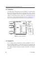
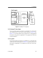
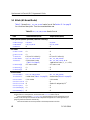
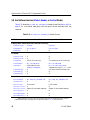
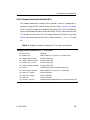
The Freeway server is a stand-alone box with pre-installed ICPs. It provides multiple
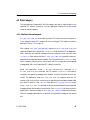
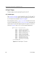
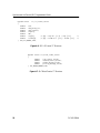
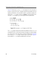
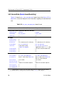
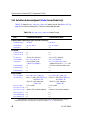
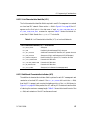
data links and a variety of network services to LAN-based clients. Figure 1–1 shows a
Freeway server configuration where the client application communicates with the
Freeway ICPs using Simpact’s data link interface (DLI). Client applications can use
either the DLI or socket interface, as described in Section 1.3.1 and Section 1.3.3. A
variety of client operating systems are supported (UNIX, VMS, and Windows NT).
Freeway Server
Application DLI
n
Client n
Server
Processor
SCADA
Defense
ICP
Commercial
X.25
Bisync
HDLC . . .
ICP
3413
…
Client 2
Ethernet LAN
Application DLI
2
AAAAA
AAAAA
AA
AAAAA
AA
AAAAAAA
AAAAA
AAAAAAA
AA
AAAAA
AAAAAAA
AA
AAAAA
AA
AAAAAAA
WAN Protocol
Options
WAN
Interface
Processors
…
Client 1
Industry Standard Bus
Application DLI
1
Financial
SWIFT
CHIPS
Telerate
Telekurs
Reuters
40+ Market
Feeds . . .
Figure 1–1: Freeway Configuration
1.2.2 Embedded ICPs
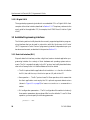
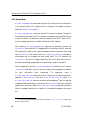
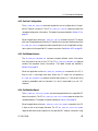
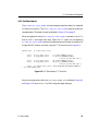
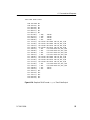
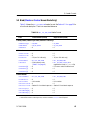
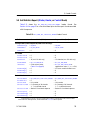
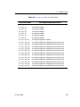
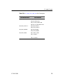
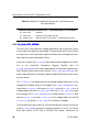
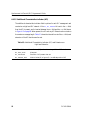
An ICP installed in a user-provided computer is called an “embedded” ICP. Figure 1–2
shows one possible embedded ICP environment where the client application uses
Simpact’s DLI programming interface. The currently supported operating systems and
their respective supported programming interfaces are described in the following
subsections.
16
DC 900-1564A
1: Introduction
Client Computer
WAN Protocol
Options
SCADA
Embedded ICP
Defense
Commercial
X.25
Bisync
HDLC . . .
Simpact
WAN Protocol
Software
Financial
SWIFT
CHIPS
Telerate
Telekurs
Reuters
40+ Market
Feeds . . .
3414
Application DLI
n
Industry Standard Bus
…
Application DLI
2
Simpact Driver
Application DLI
1
AAA
AAA
AAA
AAA
AAA
AAA
AAA
AAA
AAA
AAA
AAA
AAA
AAA
AAA
AAA
AAA
AAA
AAA
AAA
AAA
AAA
AAA
Figure 1–2: Embedded ICP Configuration
1.2.2.1 Windows NT (Intel or Alpha)
The two supported programming interfaces for an embedded ICP in a Windows NT
client computer are the DLI and the driver interface, described in Section 1.3.1 and
Section 1.3.2. The primary references are the Freeway Data Link Interface Reference
Guide and the user’s guide for the applicable ICP (for example, the ICP2432 User’s
Guide for Windows NT).
1.2.2.2 OpenVMS
The supported programming interface for an embedded ICP in an OpenVMS client
computer is the driver interface, described in Section 1.3.2. The primary reference is the
user’s guide for the applicable ICP (for example, the ICP2432 User’s Guide for OpenVMS Alpha).
DC 900-1564A
17
Synchronous Link Control (SLC) Programmer’s Guide
1.2.2.3 Digital UNIX
The supported programming interface for an embedded ICP in a Digital UNIX client
computer is the driver interface, described in Section 1.3.2. The primary reference is the
user’s guide for the applicable ICP (for example, the ICP2432 User’s Guide for Digital
UNIX).
1.3 Available Programming Interfaces
The following sections briefly describe the currently supported application programming interfaces that can be used in conjunction with this Synchronous Link Control
(SLC) Programmer’s Guide. Choice of programming interface is dependent upon your
hardware environment, as described in the previous Section 1.2.
1.3.1 Data Link Interface (DLI)
Simpact’s data link interface provides a high-level, session-oriented application programming interface for a variety of client hardware and operating system environments. The DLI concepts that apply to the SLC protocol are briefly described below;
refer to the Freeway Data Link Interface Reference Guide for details.
•
The DLI requires that the application first invoke the dlInit function to initialize
the DLI, then call the dlOpen function to open an I/O path to the ICP.
•
Raw operation — The SLC protocol uses DLI Raw operation, which means that
the client application must employ the DLI optional arguments data structure
(shown in Figure 5–1 on page 59) to issue dlRead and dlWrite commands to a
session.
•
DLI configuration parameters — The DLI configuration file needs to include only
those session parameters whose values differ from the defaults. To use DLI Raw
operation, you must specify the following parameter:
protocol = “raw”
18
DC 900-1564A
1: Introduction
•
An example SLC test program and supporting DLI and TSI configuration files are
provided with the SLC product, as listed below. To run the loopback test program,
refer to the Loopback Test Procedures document (for the Freeway server) or the
appropriate user’s guide for your embedded ICP and operating system (for example, the ICP2432 User’s Guide for Windows NT).
Non-blocking I/O
Test Program
DLI Configuration
File Name
TSI Configuration
File Name
slcalp.c
slcaldcfg
slcaltcfg
1.3.2 Driver Interface
The driver interface requires the client application to make low-level calls directly to the
ICP’s device driver. The driver interface is used when the DLI is not available for a particular environment, or when there is a programming requirement to bypass the DLI.
To perform I/O functions, refer to the driver interface document (the typical document
naming convention is ICP2432 User’s Guide for <Specific Operating System>). Then
refer to Chapter 5 of this Synchronous Link Control (SLC) Programmer’s Guide for the
protocol-specific header formats. The header formats are very similar between the DLI
and driver interfaces.
1.3.3 Socket Interface (Freeway Server Only)
The socket interface is available only for the Freeway server environment. Client applications can submit I/O requests directly to the BSD socket or, alternatively, the application can interface to Simpact’s transport subsystem interface (TSI) layer, which allows
the TSI to perform some of the header management. The primary reference is the
Freeway Client-Server Interface Control Document, which provides complete header format descriptions.
DC 900-1564A
19
Synchronous Link Control (SLC) Programmer’s Guide
20
DC 900-1564A
Chapter
2
SLC Protocol
Theory of Operation
Simpact’s SLC protocol software running on the ICP provides the application with significant control over SLC operations while reducing the overall processing burden on
the application. This chapter identifies the principal features of the SLC protocol that
are under application control.
2.1 SLC Envelope Service
An SLC envelope consists of leading SYN characters, the DLE control character, the
ETB control character and the trailing block check character (BCC) for each SLC block.
The SLC software on the ICP always provides the SLC envelope for frames transmitted
and removes the SLC envelope from frames received. The ICP generates the BCC for
frames transmitted and checks the BCC in frames received.
When the application configures an ICP link for SLC envelope service, the application
assumes full responsibility for SLC frame content between the DLE and ETB control
characters provided by the SLC envelope. In this case, the application must implement
all message handling procedures, block handling procedures, and link control procedures of the SLC protocol.
2.2 SLC Protocol Service
When the application configures an ICP link for SLC protocol service, the ICP enhances
the basic SLC envelope service to provide additional SLC protocol support. These additional services include network-level support, message blocking support, multi-channel support, retransmission support, safe store support, and stop/resume flow support.
DC 900-1564A
21
Synchronous Link Control (SLC) Programmer’s Guide
2.2.1 Network-level Support
When the application configures an ICP link for SLC protocol service, it specifies
whether high-level network service or low-level network service is required. The application formats each outgoing message and interprets each incoming message, in conformance with the message format for the specified network-level service.
2.2.2 Message Blocking Support
Message blocking support allows the application to send and receive each message in its
entirety. The application specifies the attributes of each message sent, and the SLC protocol reports the attributes of each message received.
The ICP handles the message blocking and block handling procedures of the SLC protocol. The ICP provides generation and checking of the transmission sequence identifier and the message block identifier within information blocks, as well as automatic
link control block generation and checking for block acknowledgment.
2.2.3 Multi-channel Support
Multi-channel support allows the application to assign up to seven ICP links to support
an SLC network connection. Use of multi-channel support increases the traffic
throughput capacity of an SLC network connection by distributing message traffic over
multiple physical communications channels.
2.2.4 Retransmission Support
Retransmission support allows the application to send a message once, relying upon the
ICP to handle both block-level and message-level retransmission requirements of the
SLC protocol. After a configurable number of successive message retransmissions without receipt of the corresponding acknowledgment, the ICP reports the failure to the
application.
22
DC 900-1564A
2: SLC Protocol Theory of Operation
An application can restrict the ICP to block-level retransmissions by setting the maximum number of message transmission attempts (N3) for the ICP link to 1.
2.2.5 Safe Store Support
Safe store support allows the application to control when each received message is
acknowledged, and to know when each transmitted message has been acknowledged.
For outgoing traffic, the application assigns a message label to each transmitted message. The ICP reports receipt of the corresponding acknowledgment.
For incoming traffic, the SLC protocol reports the message label associated with each
message received. The application completes all necessary message protection processing, then sends an acknowledgment to the SLC protocol service on the ICP.
2.2.6 Flow Control Support
Flow control support includes both operator-initiated and automatic flow control.
Operator control can be used per-channel either to command local operational
changes, or to send a flow-control request to the remote site.
For both low-level networks and high-level networks, the SLC protocol defines channel
flow control by means of link control blocks. The SLC software on the ICP conforms to
flow procedures automatically, except when an overriding operator request is in force.
When the ICP receives any link control block that exerts stop/resume flow control, the
ICP sends a DLI_PROT_CONTROL response to any associated applications with Control
access or Master access. See Table 4–1 on page 33 and Section 5.4 on page 65.
For high-level networks, the SLC protocol also defines network flow control by means
of network control blocks. The application reads or writes an individual network control block as a special form of the DLI_PROT_SEND_PRIOR_DATA command or response
(Section 5.13 on page 76).
DC 900-1564A
23
Synchronous Link Control (SLC) Programmer’s Guide
24
DC 900-1564A
Chapter
3
Typical Sequence
of Operations
3.1 Initialization
Section 1.3 on page 18 summarizes the programming interfaces available for use with
the ICP. In all cases, the application first must perform any initialization required by the
selected programming interface, and then must open an I/O path to the ICP prior to
writing commands or reading responses to the protocol services on the ICP.
After the application establishes an I/O path to the ICP, it writes commands to the ICP,
and reads responses from the ICP. See Chapter 4 and Chapter 5 for additional details
regarding the command and response formats. This chapter describes the typical
sequence to execute selected specific operations.
The sections that follow are presented in the order in which they are generally used.
However, restrictions associated with the access mode specified when attaching an ICP
link might forbid one or more of the other listed operations.
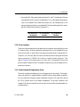
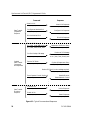
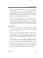
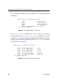
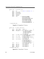
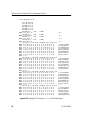
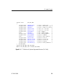
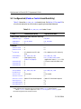
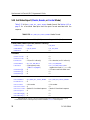
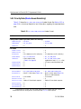
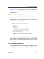
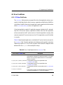
Figure 3–1 is a diagram of the commands and responses described in Section 3.2
through Section 3.13.
DC 900-1564A
25
Synchronous Link Control (SLC) Programmer’s Guide
Response
Command
Attach a Link
DLI_ICP_CMD_ATTACH
Data Transfer
Preparation
Sequence
Attach Link Response
DLI_ICP_CMD_ATTACH
Configure an Attached Link
DLI_PROT_CFG_LINK
Configure Link Response
DLI_PROT_CFG_LINK
Bind an Attached Link
DLI_ICP_CMD_BIND
Bind Link Response
DLI_ICP_CMD_BIND
Send an SLC Message
DLI_PROT_SEND_NORM_DATA or
DLI_PROT_SEND_PRIOR_DATA
Response to Confirm or Deny
DLI_PROT_SAFE_STORE_ACK
Receive an SLC Message
DLI_PROT_SEND_NORM_DATA
or DLI_PROT_SEND_PRIOR_DATA
Confirm Receipt of Message
DLI_PROT_SAFE_STORE_ACK
Possible
Data Transfer
Commands
and Responses
Send an SLC Block
DLI_PROT_SEND_TRANS_DATA
(Optional) Response to Deny
DLI_PROT_SEND_TRANS_DATA
Receive SLC Block (no acknowledge required)
DLI_PROT_SEND_TRANS_DATA
Exert Operator Control (Optional)
DLI_PROT_CONTROL
.
.
.
Data Transfer
Shutdown
Sequence
Unbind a Link
DLI_ICP_CMD_UNBIND
Detach a Link
DLI_ICP_CMD_DETACH
Receive Errors or
Detect Network Control
DLI_PROT_CONTROL
Unbind Response
DLI_ICP_CMD_UNBIND
Detach Response
DLI_ICP_CMD_DETACH
Figure 3–1: Typical Commands and Responses
26
DC 900-1564A
3: Typical Sequence of Operations
3.2 Attaching a Link
The application must successfully attach an ICP link before it can configure, bind, read
from, or write to that link. To attach a link, the application must perform the actions
listed below.
•
The application writes a DLI_ICP_CMD_ATTACH command. This allocates the ICP
link for application use under the rules for the access mode specified in the
request, and associates a session with that link and access mode (defined in
Table 4–1 on page 33).
•
The application reads a DLI_ICP_CMD_ATTACH response with a status field that confirms or denies the request. The returned session identifier is used on all subsequent DLI_ICP_CMD_WRITE requests.
3.3 Configuring an Attached Link
After the application attaches an ICP link with either Master or Control access mode, it
can configure the link prior to binding the link. If a competing application currently has
the link bound, the link cannot be configured. If the default configuration for the link
is suitable, configuration is not required. To configure a link, the application must perform the actions listed below.
•
The application writes a DLI_PROT_CFG_LINK command.
•
The application reads a DLI_PROT_CFG_LINK response with a status field that confirms or denies the request.
3.4 Binding an Attached Link
After the application attaches an ICP link with either Master or Control access mode, it
can bind the link. If the link is configured for low-level or high-level SLC network service, then binding a link places it online for SLC message transfer. If the link is config-
DC 900-1564A
27
Synchronous Link Control (SLC) Programmer’s Guide
ured for SLC envelope service (default), then binding a link places it online for SLC
block transfer. To bind a link, the application must perform the actions listed below.
•
The application writes a DLI_ICP_CMD_BIND command.
•
The application reads a DLI_ICP_CMD_BIND response with a status field that confirms or denies the request.
3.5 Sending an SLC Message
If an ICP link is configured for low-level or high-level SLC network service, then after
the application attaches the ICP link with Master access mode and binds the link, it can
send data messages to the SLC network via the ICP link. To write a message, the application must perform the actions listed below.
•
The
application
writes
a
DLI_PROT_SEND_NORM_DATA
command
or
a
DLI_PROT_SEND_PRIOR_DATA command. Some restrictions might apply due to the
specific configuration of the ICP link.
•
The application reads a DLI_PROT_SAFE_STORE_ACK response with a status field
that confirms or denies the request.
3.6 Receiving an SLC Message
If an ICP link is configured for low-level or high-level SLC network service, then after
the application attaches the ICP link with Master access mode and binds the link, it can
receive data messages from the SLC network via the ICP link. To read a message, the
application must perform the actions listed below.
•
The
application
reads
a
DLI_PROT_SEND_NORM_DATA
response
or
a
DLI_PROT_SEND_PRIOR_DATA response.
28
DC 900-1564A
3: Typical Sequence of Operations
•
The application writes a DLI_PROT_SAFE_STORE_ACK command that confirms
receipt. Some restrictions might apply due to the specific configuration of the ICP
link.
3.7 Sending an SLC Block
If an ICP link is configured for SLC envelope service (default), then after the application
attaches the ICP link with Master access mode and binds the link, it can send SLC blocks
to the SLC network via the ICP link. The application is responsible for conforming to
the SLC protocol restrictions on block content. To write a block, the application must
perform the actions listed below.
•
The application writes a DLI_PROT_SEND_TRANS_DATA command. There is no
acknowledgment; however, the application detects transmission errors by reading
a DLI_PROT_SEND_TRANS_DATA response with a status that indicates the error.
3.8 Receiving an SLC Block
If an ICP link is configured for SLC envelope service (default), then after the application
attaches the ICP link with Master access mode and binds the link, it can receive SLC
blocks from the SLC network via the ICP link. To read a block, the application must
perform the actions listed below.
•
The application reads a DLI_PROT_SEND_TRANS_DATA response with a status that
indicates no error. No acknowledgment is required.
3.9 Exerting Operator Control
If an ICP link is configured for low-level or high-level SLC network service, then after
the application attaches the ICP link with either Master or Control access mode and
binds the link, it can exert operator control over the link. To exert operator control, the
application must perform the actions listed below.
DC 900-1564A
29
Synchronous Link Control (SLC) Programmer’s Guide
•
The application writes a DLI_PROT_CONTROL command. There is no acknowledgment; however, the application detects errors by reading a DLI_PROT_CONTROL
response with a status that indicates the error.
3.10 Detecting Network Control
If an ICP link is configured for low-level or high-level SLC network service, then after
the application attaches the ICP link with either Master or Control access mode and
binds the link, it can detect network control over the link. To detect network control,
the application must perform the actions listed below.
•
The application reads a DLI_PROT_CONTROL response.
3.11 Unbinding a Link
After the application attaches the ICP link with either Master or Control access mode
and binds the link, it can unbind the link. Unbinding a link places it offline to the application. When no application with Master or Control access mode remains bound to an
ICP link, the link is offline to the SLC network. To unbind a link, the application must
perform the actions listed below.
•
The application writes a DLI_ICP_CMD_UNBIND command.
•
The application reads a DLI_ICP_CMD_UNBIND response with a status field that confirms or denies the request.
3.12 Reading Reports
After the application attaches an ICP link, it can read reports. The application can also
read reports after binding the link. Several types of reports are available. To read a specific report, the application must perform the actions listed below.
•
The application writes a command requesting the desired report. Supported
report requests are:
30
DC 900-1564A
3: Typical Sequence of Operations
DLI_PROT_GET_BUF_REPORT
DLI_PROT_GET_LINK_CFG
DLI_PROT_GET_SOFTWARE_VER
DLI_PROT_GET_STATISTICS_REPORT
DLI_PROT_GET_STATUS_REPORT
•
The application reads the report response of the same type.
3.13 Detaching a Link
After the application attaches an ICP link, it can detach the link. Detaching a link relinquishes application access to the link. If an application binds the ICP link, and detaches
the link without first unbinding, the ICP quietly handles the implied unbind, then finishes detaching the application. To detach a link, the application must perform the
actions listed below.
•
The application writes a DLI_ICP_CMD_DETACH command.
•
The application reads a DLI_ICP_CMD_DETACH response with a status field that confirms or denies the request.
3.14 Termination
Section 1.3 on page 18 summarizes the programming interface available for use with
the ICP. In all cases the application should be designed to perform the termination
sequence recommended by the selected programming interface prior to terminating
application execution. An orderly shutdown may be required to successfully close the
I/O path to the ICP, release allocated system resources, and complete the capture of
trace or log information.
DC 900-1564A
31
Synchronous Link Control (SLC) Programmer’s Guide
32
DC 900-1564A
Chapter
4
Commands and Responses
This chapter describes the commands written to the ICP and the responses received
from the ICP. After you are familiar with the functionality, refer to Chapter 5 for
detailed header formats to aid in writing application programs to interface to the SLC
protocol.
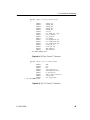
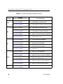
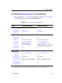
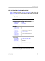
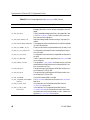
Table 4–1 defines the access modes required for using specific categories of commands
and responses. The DLI_ICP_CMD_ATTACH command (Section 4.1.1 on page 35 and
Section 5.1 on page 62) establishes the access mode. Table 4–2 summarizes the categories, which are explained further in the remainder of this chapter.
Table 4–1: Access Modes
Access
Mode
Code
Applicable Command/Response Categories
(see Table 4–2)
Master
SLC_MASTER_MODE
Can use the Access, Link, Data and Report categories
Reader
SLC_READER_MODE
Can only use the Access and Report categories
Control
SLC_CONTROL_MODE Can only use the Access, Link and Report categories
Trace
SLC_TRACE_MODE
DC 900-1564A
Can only use the Access and Trace categories
33
Synchronous Link Control (SLC) Programmer’s Guide
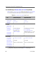
Table 4–2: Command and Response Category Summary
Category
Code and
Description Reference Section
DLI_ICP_CMD_ATTACH
(Section 4.1.1 on page 35)
Access
(Section 4.1) DLI_ICP_CMD_DETACH
(Section 4.1.2 on page 35)
Protocol Usage
Write: Request SLC network access
Read: Confirm/deny SLC network access
Write: Relinquish SLC network access
Read: Confirm/deny SLC network access relinquished
DLI_ICP_CMD_BIND
(Section 4.2.1 on page 36)
Write: Request SLC network connect
Read: Confirm/deny SLC network connect
DLI_ICP_CMD_UNBIND
(Section 4.2.2 on page 36)
Write: Request SLC network disconnect
Read: Confirm/deny SLC network disconnect
Link
(Section 4.2) DLI_PROT_CFG_LINK
(Section 4.2.3 on page 36)
Write: Set SLC network connection configuration
Read: Confirm/deny SLC network connection
configuration
DLI_PROT_CONTROL
(Section 4.2.4 on page 40)
Write: Exert operator control
Read: Report network control
DLI_PROT_SAFE_STORE_ACK
(Section 4.3.1 on page 41)
Write: Transmit message acknowledgment
Read: Receive message acknowledgment
DLI_PROT_SEND_NORM_DATA
(Section 4.3.2 on page 42)
Write: Transmit low-priority message
Read: Receive low-priority message
Data
(Section 4.3) DLI_PROT_SEND_PRIOR_DATA
(Section 4.3.3 on page 43)
Write: Transmit high-priority message
Read: Receive high-priority message
DLI_PROT_SEND_TRANS_DATA
(Section 4.3.4 on page 45)
Write: Transmit block
Read: Receive block
DLI_PROT_GET_BUF_REPORT
(Section 4.4.1 on page 46)
Write: Query SLC buffer usage status
Read: Report SLC buffer usage status
DLI_PROT_GET_LINK_CFG
(Section 4.4.2 on page 47)
Write: Query SLC network connection configuration
Read: Report SLC network connection configuration
Report
DLI_PROT_GET_SOFTWARE_VER
(Section 4.4) (Section 4.4.3 on page 47)
Write: Query SLC software version
Read: Report SLC software version
DLI_PROT_GET_STATISTICS_REPORT Write: Query SLC network connection statistics
(Section 4.4.4 on page 47)
Read: Report SLC network connection statistics
DLI_PROT_GET_STATUS_REPORT
(Section 4.4.5 on page 51)
Trace
DLI_PROT_LINK_TRACE_DATA
(Section 4.5) (Section 4.5.1 on page 53)
34
Write: Query SLC network connection status
Read: Report SLC network connection status
Read only
DC 900-1564A
4: Commands and Responses
4.1 Access Category
The commands and responses in the Access category are used to establish access control
sessions for a specified SLC network connection. Several access modes are supported:
Master, Reader, Control, or Trace (refer back to Table 4–1 on page 33 for a summary).
For each SLC network connection, only one application session is permitted per access
mode. The DLI_ICP_CMD_ATTACH command establishes the access mode. Also see
Section 6.2 on page 83 for suggestions on using access modes.
4.1.1 Attach
The DLI_ICP_CMD_ATTACH command obtains access to the SLC network connection
associated with a specified ICP data link. The specified ICP data link is channel 1 1 on
the SLC network connection. The corresponding DLI_ICP_CMD_ATTACH response reports
the success or failure of the request. If successful, the SLC access session ID assigned to
the application is reported. The header formats are detailed in Section 5.1 on page 62.
4.1.2 Detach
The DLI_ICP_CMD_DETACH command relinquishes access to the SLC network connection
for the ICP link and access mode associated with a specified application session. The
corresponding DLI_ICP_CMD_DETACH response reports the success or failure of the
request. The header formats are detailed in Section 5.5 on page 67.
1. When the multi-channel configuration option (Section 4.2.3 on page 36) is used, the application
must specify the ICP link configured as channel 1 on the SLC network connection.
DC 900-1564A
35
Synchronous Link Control (SLC) Programmer’s Guide
4.2 Link Category
The commands and responses in the Link category are used to enable, disable or configure a specified SLC network connection. Only an application session with Master or
Control access mode can use this category.
4.2.1 Bind
The DLI_ICP_CMD_BIND command enables the SLC network connection to which the
application has obtained access. The corresponding DLI_ICP_CMD_BIND response reports
the success or failure of the request. The header formats are detailed in Section 5.2 on
page 63.
4.2.2 Unbind
The DLI_ICP_CMD_UNBIND command disables the SLC network connection that the
application previously enabled. The corresponding DLI_ICP_CMD_UNBIND response
reports the success or failure of the request. The header formats are detailed in
Section 5.16 on page 81.
4.2.3 Configure Link
The DLI_PROT_CFG_LINK command contains configuration information as described
below for the SLC network connection associated with a specified ICP data link. The
configuration can also specify SLC channels 2…7, associating an additional ICP data
link with each channel. The application writes this command to configure an SLC network connection and clear its statistics. The corresponding DLI_PROT_CFG_LINK
response reports the success or failure of the request. The DLI_PROT_CFG_LINK header
formats are detailed in Section 5.3 on page 64.
Examples of a failed configuration request would be if a Master or Control client is
bound to the associated SLC network connection at the time of the request, or if the
command contains an invalid configuration option.
36
DC 900-1564A
4: Commands and Responses
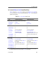
The variable-length data area of the DLI_PROT_CFG_LINK command contains a specification list of one or more configuration options for the specified SLC network connection. The available configuration options are listed in Table 4–3. Each configuration
option consists of a 16-bit unsigned integer option identifier followed by a 16-bit
unsigned integer option value. Configuration options can appear in any order. The ICP
uses the default value for each configuration option not present in the specification list.
When the SLC protocol service is configured as SLC_ENVELOPE_SERVICE, only the following configuration options are applicable:
SLC_CLOCK_CFG
SLC_EIA_CFG
SLC_T11_CFG
When the SLC protocol service is configured as SLC_LOW_LEVEL_NETWORK or
SLC_HIGH_LEVEL_NETWORK, the configuration options SLC_C2_CFG through SLC_C7_CFG
are optional. When specified, the ICP link numbers must be unique, must not conflict
with the usProtLinkID header field value, and must not conflict with ICP link numbers
assigned to channels associated with another SLC network connection.
DC 900-1564A
37
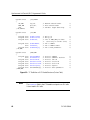
Synchronous Link Control (SLC) Programmer’s Guide
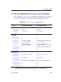
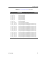
Table 4–3: SLC Configuration Options
Option
Default
Option Values
Comments
SLC_SERVICE_CFG
✓
SLC_ENVELOPE_SERVICE
SLC_LOW_LEVEL_NETWORK
SLC_HIGH_LEVEL_NETWORK
SLC Service Support
SLC_BLOCK_SCATTER
_CFG
✓
0 = Send message blocks serially
1 = Send message blocks in
parallel on multiple channels
Multi-block message channel
scatter option
SLC_BLOCK_ACK_CFG
✓
SLC_BLOCK_ACK_FAST
SLC_BLOCK_ACK_SAFE
Block-level acknowledgment
timing. SLC_BLOCK_ACK_FAST
(default) permits immediate
acknowledgment of blocks
received. SLC_BLOCK_ACK_SAFE
delays block-level acknowledgment until the application
requests acknowledgment by
sending
DLI_PROT_SAFE_STORE_ACK.
SLC_CLOCK_CFG
✓
0 = select network as clock source SLC line clock source/rate
1…SLC_CLOCK_MAXIMUM = ICP
clock source baud rate
SLC_EIA_CFG
✓
SLC_EIA_232
SLC_EIA_449
SLC_EIA_530
SLC_EIA_V35
Electrical Interface
SLC_C2_CFG
Optional
0…(n–1) where
n = number of ICP links
ICP link associated with SLC
network connection channel 2
SLC_C3_CFG
Optional
0…(n–1) where
n = number of ICP links
ICP link associated with SLC
network connection channel 3
SLC_C4_CFG
Optional
0…(n–1) where
n = number of ICP links
ICP link associated with SLC
network connection channel 4
SLC_C5_CFG
Optional
0…(n–1) where
n = number of ICP links
ICP link associated with SLC
network connection channel 5
SLC_C6_CFG
Optional
0…(n–1) where
n = number of ICP links
ICP link associated with SLC
network connection channel 6
SLC_C7_CFG
Optional
0…(n–1) where
n = number of ICP links
ICP link associated with SLC
network connection channel 7
38
DC 900-1564A
4: Commands and Responses
Table 4–3: SLC Configuration Options (Cont’d)
Option
Default
Option Values
Comments
SLC_N1_CFG
SLC_N1_DEFAULT
1…SLC_N1_MAXIMUM
Refer to IATAa
SLC_N2_CFG
SLC_N2_DEFAULT
1…SLC_N2_MAXIMUM
Refer to IATA
SLC_N3_CFG
SLC_N3_DEFAULT
1…SLC_N3_MAXIMUM
Refer to IATA
SLC_N4_CFG
SLC_N4_DEFAULT
1…SLC_N4_MAXIMUM
Refer to IATA
SLC_N5_CFG
SLC_N5_DEFAULT
1…SLC_N5_MAXIMUM
Refer to IATA
SLC_N6_CFG
SLC_N6_DEFAULT
1…SLC_N6_MAXIMUM
Refer to IATA
SLC_T1_CFG
SLC_T1_DEFAULT
1…65535 tenths of a second
Refer to IATA
SLC_T2_CFG
SLC_T2_DEFAULT
1…65535 tenths of a second
Refer to IATA
SLC_T3_CFG
SLC_T3_DEFAULT
1…65535 tenths of a second
Refer to IATA
SLC_T4_CFG
SLC_T4_DEFAULT
1…65535 tenths of a second
Refer to IATA
SLC_T5_CFG
SLC_T5_DEFAULT
1…65535 tenths of a second
Refer to IATA
SLC_T6_CFG
SLC_T6_DEFAULT
1…65535 tenths of a second
Refer to IATA
SLC_T7_CFG
SLC_T7_DEFAULT
1…65535 tenths of a second
Refer to IATA
SLC_T8_CFG
SLC_T8_DEFAULT
1…65535 tenths of a second
Refer to IATA
SLC_T9_CFG
SLC_T9_DEFAULT
1…65535 tenths of a second
Refer to IATA
SLC_T10_CFG
SLC_T10_DEFAULT 1…65535 tenths of a second
Refer to IATA
SLC_T11_CFG
SLC_T11_DEFAULT 1…65535 tenths of a second
Frame transmission time limit
a International Air Transport Association (IATA) — see the document reference on page 13 of the Preface.
DC 900-1564A
39
Synchronous Link Control (SLC) Programmer’s Guide
4.2.4 Control
DLI_PROT_CONTROL can be used only when SLC protocol service is configured. It is not
supported when SLC envelope service is configured.
An application reads a DLI_PROT_CONTROL response when the ICP receives any link control block (LCB) that exerts stop/resume flow control. An application exerts operator
control over SLC channel operation by writing a DLI_PROT_CONTROL command to the
ICP.
The ICP maintains three local operational control flags for each channel simultaneously. The opr_channel_state flag retains a value of SLC_OPR_CHANNEL_START (default)
or SLC_OPR_CHANNEL_STOP until a new value is requested. The opr_in_state flag retains
a value of SLC_OPR_IN_RESUME (default) or SLC_OPR_IN_STOP until a new value is
requested. The opr_out_state flag retains a value of SLC_OPR_OUT_RESUME (default) or
SLC_OPR_OUT_STOP until a new value is requested. The DLI_PROT_GET_STATUS_REPORT
command can be used to read the current values of these status flags (Section 5.10 on
page 72). The header formats and operator control options are detailed in Section 5.4
on page 65.
40
DC 900-1564A
4: Commands and Responses
4.3 Data Category
The commands and responses in the Data category are used to transfer data on the
specified SLC network connection. Only an application session with Master access
mode can use this category.
4.3.1 Safe Store Acknowledgment
DLI_PROT_SAFE_STORE_ACK can be used only when SLC protocol service is configured. It
is not supported when SLC envelope service is configured. The header formats are
detailed in Section 5.14 on page 78.
After reading a DLI_PROT_SEND_NORM_DATA response or a DLI_PROT_SEND_PRIOR_DATA
response, the application extracts the iProtModifier field value (the ICP message identifier), performs any required message protection operations, then using the same
iProtModifier field value writes the DLI_PROT_SAFE_STORE_ACK command to acknowl-
edge that the message has been stored safely. The ICP examines the iProtModifier field,
and if necessary transmits a link control block with the corresponding acknowledge
message label (AML) on the specified SLC network connection.
When the application writes a DLI_PROT_SEND_NORM_DATA command or a
DLI_PROT_SEND_PRIOR_DATA command, the ICP uses the iProtModifier field value to
compute a corresponding message block identifier for each information block transmitted. The application reads a DLI_PROT_SAFE_STORE_ACK response when the ICP
receives a link control block containing a corresponding acknowledge message label
from the SLC network. If the iICPStatus field value is DLI_ICP_CMD_STATUS_OK, receipt
of a DLI_PROT_SAFE_STORE_ACK response constitutes acknowledgment that the specified
message has been stored safely at a remote site. If the iICPStatus field value contains a
negative error code value, receipt of a DLI_PROT_SAFE_STORE_ACK response constitutes a
failure in message transmission or a rejection of the specified message by the remote
site.
DC 900-1564A
41
Synchronous Link Control (SLC) Programmer’s Guide
4.3.2 Normal Data
DLI_PROT_SEND_NORM_DATA can be used only when SLC protocol service is configured. It
is not supported when SLC envelope service is configured. The header formats are
detailed in Section 5.12 on page 74.
DLI_PROT_SEND_NORM_DATA contains an entire SLC low-priority message. The applica-
tion writes this command to the ICP to transmit a message through the WAN interface
to the SLC network. The application reads this response when the ICP reports a lowpriority message received from the WAN interface to the SLC network.
After reading a DLI_PROT_SEND_NORM_DATA response, the application extracts the
iProtModifier field value (the ICP message identifier consisting of the AML value and
AML descriptor), performs any required message protection operations, then using
same iProtModifier field value writes the DLI_PROT_SAFE_STORE_ACK command to
acknowledge that the message has been stored safely. The ICP examines the
iProtModifier field, and if necessary transmits a link control block with the corre-
sponding acknowledge message label on the specified SLC network connection.
When the application writes a DLI_PROT_SEND_NORM_DATA command, the ICP uses the
iProtModifier field (AML value) to compute a corresponding message block identifier
for
each
information
block
transmitted.
The
application
reads
a
DLI_PROT_SAFE_STORE_ACK response when the ICP reports a a corresponding acknowl-
edgment. If the iICPStatus field value is DLI_ICP_CMD_STATUS_OK, receipt of a
DLI_PROT_SAFE_STORE_ACK response constitutes acknowledgment2 that the specified
message has been stored safely at a remote site. If the iICPStatus field value contains a
negative error code value, receipt of a DLI_PROT_SAFE_STORE_ACK response constitutes a
failure in message transmission or a rejection of the specified message by the remote
site.
2. In the case of messages sent with no protection indicated, DLI_PROT_SAFE_STORE_ACK reports transmission success or failure.
42
DC 900-1564A
4: Commands and Responses
Table 5–16 on page 75 lists symbolic names for the DLI_PROT_SEND_NORM_DATA AML values that can appear in the iProtModifier field for both writes and reads. The validity of
these values is influenced by both the network level and the message length. An AML for
a single-block message can be used only with a message that fits within a single transmission block on the SLC network. However, an AML for a multi-block message can be
used for either a single-block message or a multi-block message.
The DLI_PROT_SEND_NORM_DATA data content is variable. It contains selected SLC information block header fields followed by the message information field. The SLC protocol
software supports a maximum message information field size of 4000 bytes for lowlevel network messages or 3840 bytes for high-level network messages. For additional
information on data content, see Section 6.4.2 on page 85 and Section 6.4.3 on page 88.
4.3.3 Priority Data
DLI_PROT_SEND_PRIOR_DATA can be used only when SLC protocol service is configured.
It is not supported when SLC envelope service is configured. The header formats are
detailed in Section 5.13 on page 76.
DLI_PROT_SEND_PRIOR_DATA contains an entire SLC high-priority message. The applica-
tion writes this command to the ICP to transmit a high-priority message through the
WAN interface to the SLC network. The application reads this response when the ICP
reports a high-priority message received from the WAN interface to the SLC network.
After reading a DLI_PROT_SEND_PRIOR_DATA response, the application extracts the
iProtModifier field value (the ICP message identifier consisting of the AML value and
AML descriptor), performs any required message protection operations, then using
same iProtModifier field value writes the DLI_PROT_SAFE_STORE_ACK command to
acknowledge that the message has been stored safely. The ICP examines the
iProtModifier field, and if necessary, transmits a link control block with the corre-
sponding acknowledge message label on the specified SLC network connection.
DC 900-1564A
43
Synchronous Link Control (SLC) Programmer’s Guide
When the application writes a DLI_PROT_SEND_PRIOR_DATA command, the ICP uses the
iProtModifier field (AML value) to compute a corresponding message block identifier
for
each
information
block
transmitted.
The
application
reads
a
DLI_PROT_SAFE_STORE_ACK response when the ICP reports a corresponding acknowl-
edgment. If the iICPStatus field value is DLI_ICP_CMD_STATUS_OK, receipt of a
DLI_PROT_SAFE_STORE_ACK response constitutes acknowledgment3 that the specified
message has been stored safely at a remote site. If the iICPStatus field value contains a
negative error code value, receipt of a DLI_PROT_SAFE_STORE_ACK response constitutes a
failure in message transmission or a rejection of the specified message by the remote
site.
Table 5–18 on page 77 lists symbolic names for the DLI_PROT_SEND_PRIOR_DATA AML
values that can appear in the iProtModifier field for both writes and reads. The validity
of these values is influenced by both the network level and the message length. An AML
for a single-block message can be used only with a message that fits within a single
transmission block on the SLC network. However, an AML for a multi-block message
can be used for either a single-block message or a multi-block message.
The DLI_PROT_SEND_PRIOR_DATA data content is variable. It contains selected SLC information block header fields followed by the (optional) message information field. The
SLC protocol software supports a maximum message information field size of 4000
bytes for low-level network messages or 3840 bytes for high-level network messages.
For additional information on data content, see Section 6.4.2 on page 85 and
Section 6.4.3 on page 88.
3. In the case of messages sent with no protection indicated, DLI_PROT_SAFE_STORE_ACK reports transmission success or failure.
44
DC 900-1564A
4: Commands and Responses
4.3.4 Transparent Data
DLI_PROT_SEND_TRANS_DATA can be used only when SLC envelope service is configured.
It can not be used when SLC protocol service is configured. The header formats are
detailed in Section 5.15 on page 80.
DLI_PROT_SEND_TRANS_DATA contains a single SLC block. The application writes this
command to the ICP to transmit a control block or an information block through the
WAN interface to the SLC network. The application reads this response when the ICP
reports a block received from the WAN interface to the SLC network. The application is
responsible for handling all SLC protocol requirements beyond the simple SLC envelope service supported by the ICP. See Section 2.1 on page 21.
DC 900-1564A
45
Synchronous Link Control (SLC) Programmer’s Guide
4.4 Report Category
The Report category is used to request specific reports from the ICP.
4.4.1 Get Buffer Report
The DLI_PROT_GET_BUF_REPORT command requests the current ICP buffer usage. The
ICP DLI_PROT_GET_BUF_REPORT response contains the requested buffer usage information. The header formats are detailed in Section 5.6 on page 68.
When the application writes a DLI_PROT_GET_BUF_REPORT command to the ICP, it does
so with a zero-length data area. The ICP DLI_PROT_GET_BUF_REPORT response data area
contains a report of current buffer usage for the entire ICP using the “C” structure format shown in Figure 4–1, where “UINT32” is a 32-bit unsigned integer data type.
typedef struct slc_buf_report_struct
{
UINT32
available_icp_block_buffers;
UINT32
available_icp_message_buffers;
UINT32
queued_rcv_empty_blocks;
UINT32
queued_rcv_link_control_blocks;
UINT32
queued_rcv_normal_blocks;
UINT32
queued_rcv_priority_blocks;
UINT32
queued_rcv_normal_message;
UINT32
queued_rcv_priority_message;
UINT32
queued_xmt_link_control_blocks;
UINT32
queued_xmt_normal_blocks;
UINT32
queued_xmt_priority_blocks;
UINT32
queued_xmt_normal_message;
UINT32
queued_xmt_priority_message;
} SLC_BUF_REPORT_TYPE;
Figure 4–1: SLC Buffer Report “C” Structure
46
DC 900-1564A
4: Commands and Responses
4.4.2 Get Link Configuration
The DLI_PROT_GET_LINK_CFG command requests the current configuration of a specified SLC network connection. The ICP DLI_PROT_GET_LINK_CFG response contains the
requested configuration information. The header formats are detailed in Section 5.7 on
page 69.
When the application writes a DLI_PROT_GET_LINK_CFG command to the ICP, it does so
with a zero-length data area. When the ICP replies to this command, the data area of the
DLI_PROT_GET_LINK_CFG response contains a specification list of all applicable configu-
ration options for the specified SLC network connection. See Section 4.2.3 on page 36.
4.4.3 Get Software Version
The DLI_PROT_GET_SOFTWARE_VER command requests software version information
from the protocol service on the ICP. The ICP DLI_PROT_GET_SOFTWARE_VER response
contains the requested version information. The header formats are detailed in
Section 5.8 on page 70.
When the application writes a DLI_PROT_GET_SOFTWARE_VER command to the ICP, it
does so with a zero-length data area. When the ICP sends the corresponding
DLI_PROT_GET_SOFTWARE_VER response, the data area contains a “c” format text string
containing embedded new-line characters (‘\n’) and is terminated by a null (‘\0’)
character.
4.4.4 Get Statistics Report
The DLI_PROT_GET_STATISTICS_REPORT command requests statistics for a specified SLC
network connection. The ICP DLI_PROT_GET_STATISTICS_REPORT response contains the
requested statistics. The header formats are detailed in Section 5.8 on page 70.
When the application writes a DLI_PROT_GET_STATISTICS_REPORT command to the ICP,
it does so with a zero-length data area. The ICP DLI_PROT_GET_STATISTICS_REPORT
response data area contains statistics for the specified SLC network connection using
DC 900-1564A
47
Synchronous Link Control (SLC) Programmer’s Guide
the “C” structure format shown in Figure 4–2, where “UINT32” is a 32-bit unsigned integer data type.
typedef struct slc_statistics_report_struct
{
UINT32
normal_message_in;
UINT32
normal_message_out;
UINT32
priority_message_in;
UINT32
priority_message_in;
struct slc_channel_counts_struct
channel;
} SLC_STATISTICS_REPORT_TYPE;
Figure 4–2: SLC Statistics Report “C” Structure
The slc_channel_counts_struct within the SLC_STATISTICS_REPORT_TYPE and each of
the structures within the slc_channel_counts_struct are defined in Figure 4–3
through Figure 4–7. Statistics for each channel associated with a specified SLC network
connection are cleared when the application writes a DLI_PROT_CFG_LINK command to
the ICP (Section 4.2.3 on page 36).
typedef struct slc_channel_counts_struct
{
struct slc_port_counts_struct
struct slc_lci_counts_struct
struct slc_lci_counts_struct
struct slc_lsi_counts_struct
struct slc_lsi_counts_struct
struct slc_block_counts_struct
struct slc_block_counts_struct
} SLC_CHANNEL_COUNTS_TYPE;
port;
lci_in;
lci_out;
lsi_in;
lsi_out;
blocks_in;
blocks_out;
Figure 4–3: SLC Channel Counts “C” Structure
48
DC 900-1564A
4: Commands and Responses
typedef struct slc_port_counts_struct
{
UINT32
change_cts;
UINT32
change_dcd;
UINT32
change_dsr;
UINT32
change_dtr;
UINT32
change_rts;
UINT32
rcv_bcc;
UINT32
rcv_frame_too_long;
UINT32
rcv_no_buffer;
UINT32
rcv_overrun;
UNIT32
rcv_parity;
UINT32
rcv_unexpected_dle;
UINT32
rcv_unexpected_etb;
UINT32
rcv_unexpected_syn;
UINT32
reset_tsi_in;
UINT32
reset_tsi_out;
UINT32
xmt_timeout;
UNIT32
xmt_underrun;
} SLC_PORT_COUNTS_TYPE;
Figure 4–4: SLC Port Counts “C” Structure
}
typedef struct slc_lci_counts_struct
{
UINT32
pdm;
UINT32
aci;
UINT32
hld;
UINT32
full_protection;
UINT32
limited_protection;
UINT32
no_protection;
UINT32
end_to_end_protection;
UINT32
last_block;
UINT32
not_last_block;
SLC_LCI_COUNTS_TYPE;
Figure 4–5: SLC LCI Counts “C” Structure
DC 900-1564A
49
Synchronous Link Control (SLC) Programmer’s Guide
typedef struct
slc_lsi_counts_struct
{
UINT32
ack;
UINT32
nak_parity_bcc;
UINT32
nak_sequence;
UINT32
enquiry;
UINT32
aml;
UINT32
stop[8];
/* [0] = stop all; [1…7] = stop [1…7]
UINT32
resume[8];
/* [0] = resume all; [1…7] = resume [1…7]
} SLC_LSI_COUNTS_TYPE;
*/
*/
Figure 4–6: SLC LSI Counts “C” Structure
typedef struct slc_block_counts_struct
{
UINT32
link_control_blocks;
UINT32
network_control_blocks;
UINT32
normal_message_blocks;
UINT32
priority_message_blocks;
} SLC_BLOCK_COUNTS_TYPE;
Figure 4–7: SLC Block Counts “C” Structure
50
DC 900-1564A
4: Commands and Responses
4.4.5 Get Status Report
The DLI_PROT_GET_STATUS_REPORT command requests operational status for a specified
SLC network connection. The ICP DLI_PROT_GET_STATUS_REPORT response contains the
requested status. The header formats are detailed in Section 5.10 on page 72.
When the application writes a DLI_PROT_GET_STATUS_REPORT command to the ICP, it
does so with a zero-length data area. When the ICP sends the corresponding
DLI_PROT_GET_STATUS_REPORT response, the data area reports the status of operation for
the specified SLC network connection using the “C” structure format in Figure 4–8.
typedef struct
{
struct
struct
}
slc_status_report_struct
slc_msg_status_struct
slc_msg_status_struct
rcv_normal [NUMBER_OF_AMLS];
rcv_priority [NUMBER_OF_AMLS];
/* One per possible AML value */
struct
slc_msg_status_struct
xmt_normal [NUMBER_OF_AMLS];
struct
slc_msg_status_struct
xmt_priority [NUMBER_OF_AMLS];
/* One per possible AML value */
struct
slc_channel_status_struct channel[CONSTANT_MAX_NETWORK_CHANNELS];
SLC_STATUS_REPORT_TYPE;
Figure 4–8: SLC Status Report “C” Structure
Each structure type shown within the SLC_STATUS_REPORT_TYPE is defined in Figure 4–9
and Figure 4–10, where “UINT16” is a 16-bit unsigned integer data type.
DC 900-1564A
51
Synchronous Link Control (SLC) Programmer’s Guide
typedef struct
{
UINT16
UINT16
UINT16
UINT16
UINT16
UINT16
UINT16
UINT16
}
slc_msg_status_struct
aml;
/* See Table 5–16 and Table 5–18 */
blocks_acked;
blocks_failed;
blocks_pending;
blocks_total;
characters;
reserved;
state;
/* SLC_MSG_AML_AVAILABLE,
SLC_MSG_AML_FORBIDDEN,
SLC_MSG_PENDING_TO_HOST,
SLC_MSG_RECEIVING_FROM_NETWORK,
SLC_MSG_REPORTING_TO_HOST,
SLC_MSG_PENDING_TO_NETWORK,
SLC_MSG_SENDING_TO_NETWORK,
SLC_MSG_WAITING_NETWORK_ACK,
or SLC_MSG_WAITING_HOST_ACK
*/
SLC_MSG_STATUS_TYPE;
Figure 4–9: SLC Message Status “C” Structure
typedef struct
{
UINT16
UINT16
UINT16
slc_channel_status_struct
channel_number; /* Number 1…7
*/
status_validity; /* 0 = Invalid;
1 = Valid
*/
flow_state;
/* SLC_FLOW_RESUME (default),
SLC_FLOW_FAULT_ENQUIRY,
SLC_FLOW_INITIALIZATION,
SLC_FLOW_FAILURE,
or SLC_FLOW_STOP
*/
UINT16
opr_channel_state;/* SLC_OPR_CHANNEL_START (default)
or SLC_OPR_CHANNEL_STOP
*/
UINT16
opr_in_state;
/* SLC_OPR_IN_RESUME (default)
or SLC_OPR_IN_STOP
*/
UINT16
opr_out_state;
/* SLC_OPR_OUT_RESUME (default)
or SLC_OPR_OUT_STOP
*/
UINT16
opr_send_state; /* zero (default)
or SLC_OPR_SEND_STOP_ALL
or SLC_OPR_SEND_STOP_C1…_C7
or SLC_OPR_SEND_RESUME_ALL
or SLC_OPR_SEND_RESUME_C1…_C7 */
UINT16
state_cts;
/* SLC_SIG_OFF, SLC_SIG_ON,
or SLC_SIG_UNSTABLE
*/
UINT16
state_dcd;
/* SLC_SIG_OFF…etc.
*/
UINT16
state_dsr;
/* SLC_SIG_OFF…etc.
*/
UINT16
state_dtr;
/* SLC_SIG_OFF…etc.
*/
UINT16
state_rts;
/* SLC_SIG_OFF…etc.
*/
} SLC_CHANNEL_STATUS_TYPE;
Figure 4–10: SLC Channel Status “C” Structure
52
DC 900-1564A
4: Commands and Responses
4.5 Trace Category
4.5.1 Link Trace Data
The DLI_PROT_LINK_TRACE_DATA response contains one or more trace report entries.
Each report entry contains an event_header_struct structure (Figure 4–11), followed
by a 16-bit sample size, a 16-bit packet size, and an optional data trace field.
Each trace report (Figure 4–12) begins on a 32-bit boundary within the data area. If the
optional data trace (of the preceding trace report entry) does not end on a proper
boundary, the trace report is padded to the next 32-bit bound.
In the client software directory for the SLC protocol, the slc_trac.h file identifies these
two structures. The client program slc_trac.c provides an example of how to access
the SLC protocol line tracing capability.
typedef struct
{
INT8
}
event_header_struct
channel;
/* 0 == All network channels
N == Nth network channel
*/
INT8
code;
INT8
id;
INT8
status;
UINT32
msTimeStamp;
EVENT_HEADER_TYPE;
Figure 4–11: SLC Trace Event Header “C” Structure
typedef struct
event_report_struct
{
struct event_header_struct event;
INT16
sample_size;
/* Sample size sent to client
INT16
packet_size;
/* Packet size received on data link
char
sample[4];
/* Run-time dimension == sample_size
/* Padded to next LONG bound
} EVENT_REPORT_TYPE;
*/
*/
*/
*/
Figure 4–12: SLC Trace Report “C” Structure
DC 900-1564A
53
Synchronous Link Control (SLC) Programmer’s Guide
Figure 4–13 shows how to run the slc_trac trace program from the command-line
prompt on a typical UNIX client. The program requires three parameters, which the
operator provides either on the command-line itself, or as answers to questions displayed by the slc_trac program (as shown in bold type). The actual method for executing the slc_trac program on your client may differ from the method shown.
prompt% slc_trac
ICP board number (0-5) [0]? 0
ICP link number (0-7) [0]? 0
Trace mode (0=brief, 1=full) [0]?
0
SLC Trace Program.
ICP board number: 0
ICP link number: 0
DLI session name: B0L0
Figure 4–13: Running the slc_trac Program on a UNIX Client
The slc_trac program outputs all trace data to the standard error device (stderr) as
formatted ASCII text. In most client environments, the operator can redirect standard
error output to a file or view output directly on the terminal display screen. Figure 4–14
shows a sample of slc_trac program trace data output in brief format. Figure 4–15
shows a sample of slc_trac program trace data output in full format.
54
DC 900-1564A
4: Commands and Responses
TIME-STAMP EVENT STATUS
1240.705
1240.805
1241.005
1241.005
1241.005
1241.005
1241.015
1241.025
1241.040
1241.040
1241.155
1241.155
1241.270
1241.270
1241.280
1241.280
1241.305
1241.320
1241.440
1241.450
1241.555
1241.565
1241.565
1241.580
1241.580
1241.590
1241.805
1241.805
1241.910
1242.010
1242.010
TRACE
DTR_1
DCD_1
DSR_1
RTS_1
CTS_1
XMT_1
RCV_1
RCV_1
XMT_1
RCV_1
XMT_1
RCV_1
XMT_1
RCV_1
XMT_1
XMT_1
RCV_1
XMT_1
RCV_1
XMT_1
RCV_1
XMT_1
RCV_1
XMT_1
RCV_1
RTS_1
DTR_1
CTS_1
DCD_1
DSR_1
ON
ON
ON
ON
ON
ON
5
5
5
5
130
130
130
130
5
5
5
5
130
130
130
130
5
5
5
5
OFF
OFF
OFF
OFF
OFF
ENQ
ENQ
ACK
ACK
TSN=01
TSN=01
TSN=02
TSN=02
AML
AML
AML
AML
TSN=03
TSN=03
TSN=04
TSN=04
AML
AML
ACK
ACK
TSN=00
TSN=00
TSN=00
TSN=00
MBI=0x00
MBI=0x00
MBI=0x20
MBI=0x20
Code=0x01
Code=0x01
Code=0x21
Code=0x21
MBI=0x00
MBI=0x00
MBI=0x20
MBI=0x20
Code=0x01
Code=0x01
TSN=04
TSN=04
AML=SLC_AML_A_ND
AML=SLC_AML_A_ND
AML=SLC_AML_B_ND
AML=SLC_AML_B_ND
Name=SLC_AML_A_ND
Name=SLC_AML_A_ND
Name=SLC_AML_B_ND
Name=SLC_AML_B_ND
AML=SLC_AML_A_ND
AML=SLC_AML_A_ND
AML=SLC_AML_B_ND
AML=SLC_AML_B_ND
Name=SLC_AML_A_ND
Name=SLC_AML_A_ND
Figure 4–14: Sample of Brief Format slc_trac Trace Data Output
DC 900-1564A
55
Synchronous Link Control (SLC) Programmer’s Guide
TIME-STAMP EVENT STATUS
1289.710 TRACE ON
1289.810 DTR_1 ON
1290.010 DCD_1 ON
1290.010 DSR_1 ON
1290.010 RTS_1 ON
1290.010 CTS_1 ON
1290.020 XMT_1
5 ENQ
0000: 10 24 40 17 63
1290.030 RCV_1
5 ENQ
0000: 10 24 40 17 63
1290.045 RCV_1
5 ACK
0000: 10 21 40 17 66
1290.045 XMT_1
5 ACK
0000: 10 21 40 17 66
1290.160 RCV_1 130 TSN=01
0000: 10 61 00 41 38 37 36 35
0010: 62 43 63 44 64 45 65 46
0020: 6a 4b 6b 4c 6c 4d 6d 4e
0030: 72 53 73 54 74 55 75 56
0040: 7a 30 31 32 33 34 35 36
0050: 46 47 48 49 4a 4b 4c 4d
0060: 56 57 58 59 5a 61 62 63
0070: 6c 6d 6e 6f 70 71 72 73
0080: 17 13
1290.160 XMT_1 130 TSN=01
0000: 10 61 00 41 31 32 33 34
0010: 44 45 46 47 48 49 4a 4b
0020: 54 55 56 57 58 59 5a 61
0030: 6a 6b 6c 6d 6e 6f 70 71
0040: 7a 39 38 37 36 35 34 33
0050: 63 44 64 45 65 46 66 47
0060: 6b 4c 6c 4d 6d 4e 6e 4f
0070: 73 54 74 55 75 56 76 57
0080: 17 1a
1290.275 RCV_1 130 TSN=02
0000: 10 62 20 41 37 36 35 34
0010: 43 63 44 64 45 65 46 66
0020: 4b 6b 4c 6c 4d 6d 4e 6e
0030: 53 73 54 74 55 75 56 76
0040: 30 31 32 33 34 35 36 37
0050: 47 48 49 4a 4b 4c 4d 4e
0060: 57 58 59 5a 61 62 63 64
0070: 6d 6e 6f 70 71 72 73 74
0080: 17 31
1290.275 XMT_1 130 TSN=02
0000: 10 62 20 41 32 33 34 35
0010: 45 46 47 48 49 4a 4b 4c
0020: 55 56 57 58 59 5a 61 62
0030: 6b 6c 6d 6e 6f 70 71 72
0040: 39 38 37 36 35 34 33 32
0050: 44 64 45 65 46 66 47 67
TSN=00
[email protected]
TSN=00
[email protected]
TSN=00
[email protected]
TSN=00
[email protected]
MBI=0x00 AML=SLC_AML_A_ND
34 33 32 31 30 41 61 42
66 47 67 48 68 49 69 4a
6e 4f 6f 50 70 51 71 52
76 57 77 58 78 59 79 5a
37 38 39 41 42 43 44 45
4e 4f 50 51 52 53 54 55
64 65 66 67 68 69 6a 6b
74 75 76 77 78 79 7a 0d
MBI=0x00 AML=SLC_AML_A_ND
35 36 37 38 39 41 42 43
4c 4d 4e 4f 50 51 52 53
62 63 64 65 66 67 68 69
72 73 74 75 76 77 78 79
32 31 30 41 61 42 62 43
67 48 68 49 69 4a 6a 4b
6f 50 70 51 71 52 72 53
77 58 78 59 79 5a 7a 0d
MBI=0x20 AML=SLC_AML_B_ND
33 32 31 30 41 61 42 62
47 67 48 68 49 69 4a 6a
4f 6f 50 70 51 71 52 72
57 77 58 78 59 79 5a 7a
38 39 41 42 43 44 45 46
4f 50 51 52 53 54 55 56
65 66 67 68 69 6a 6b 6c
75 76 77 78 79 7a 39 0d
MBI=0x20 AML=SLC_AML_B_ND
36 37 38 39 41 42 43 44
4d 4e 4f 50 51 52 53 54
63 64 65 66 67 68 69 6a
73 74 75 76 77 78 79 7a
31 30 41 61 42 62 43 63
48 68 49 69 4a 6a 4b 6b
.a.A876543210AaB
bCcDdEeFfGgHhIiJ
jKkLlMmNnOoPpQqR
rSsTtUuVvWwXxYyZ
z0123456789ABCDE
FGHIJKLMNOPQRSTU
VWXYZabcdefghijk
lmnopqrstuvwxyz.
..
.a.A123456789ABC
DEFGHIJKLMNOPQRS
TUVWXYZabcdefghi
jklmnopqrstuvwxy
z9876543210AaBbC
cDdEeFfGgHhIiJjK
kLlMmNnOoPpQqRrS
sTtUuVvWwXxYyZz.
..
.b A76543210AaBb
CcDdEeFfGgHhIiJj
KkLlMmNnOoPpQqRr
SsTtUuVvWwXxYyZz
0123456789ABCDEF
GHIJKLMNOPQRSTUV
WXYZabcdefghijkl
mnopqrstuvwxyz9.
.1
.b A23456789ABCD
EFGHIJKLMNOPQRST
UVWXYZabcdefghij
klmnopqrstuvwxyz
9876543210AaBbCc
DdEeFfGgHhIiJjKk^L
Figure 4–15: Sample of Full Format slc_trac Trace Data Output
56
DC 900-1564A
Chapter
5
Header Formats
The application and the SLC protocol software on the ICP communicate by sending
commands and responses. This chapter identifies the format of each command and
response. Table 5–1 on page 58 gives an overview of the categories of commands and
responses used by the SLC protocol. The individual header formats are presented alphabetically by command/response name in Section 5.1 through Section 5.16.
Figure 5–1 gives the “C” definition of the optional arguments structure (DLI_OPT_ARGS)
used when making calls to the DLI interface. Figure 5–2 shows a typical definition of
the comparable structures used when making calls directly to a driver interface.
Table 5–2 compares the fields used to interface to the DLI versus a driver and also gives
a general overview of the typical field values used for the SLC protocol, though there are
some request-specific differences noted in the following sections. Refer to the Freeway
Leslie...look
into finding or
creating a
similar table
for the socket
interface...
later.
Client-Server Interface Control Document for using the socket interface.
Note
DC 900-1564A
Most of the fields within the ICP_PACKET structure are in network
byte-order. However, each field name that starts with “usProt” or
“iProt” is in client byte-order. The client must declare its byteorder characteristics in the iICPStatus field of each command
when making non-DLI calls.
57
Synchronous Link Control (SLC) Programmer’s Guide
Table 5–1: Command and Response Category Summary
Category
Access
Link
Data
Report
Code and
Header Format Reference Section
SLC Protocol Usage
DLI_ICP_CMD_ATTACH
(Section 5.1 on page 62)
Write: Request SLC network access
Read: Confirm/deny SLC network access
DLI_ICP_CMD_DETACH
(Section 5.5 on page 67)
Write: Relinquish SLC network access
Read: Confirm/deny SLC network access relinquished
DLI_ICP_CMD_BIND
(Section 5.2 on page 63)
Write: Request SLC network connect
Read: Confirm/deny SLC network connect
DLI_ICP_CMD_UNBIND
(Section 5.16 on page 81)
Write: Request SLC network disconnect
Read: Confirm/deny SLC network disconnect
DLI_PROT_CFG_LINK
(Section 5.3 on page 64)
Write: Set SLC network connection configuration
Read: Report SLC network connection configuration
DLI_PROT_CONTROL
(Section 5.4 on page 65)
Write: Exert operator control
Read: Report network control
DLI_PROT_SAFE_STORE_ACK
(Section 5.14 on page 78)
Write: Transmit message acknowledgment
Read: Receive message acknowledgment
DLI_PROT_SEND_NORM_DATA
(Section 5.12 on page 74)
Write: Transmit low-priority message
Read: Receive low-priority message
DLI_PROT_SEND_PRIOR_DATA
(Section 5.13 on page 76)
Write: Transmit high-priority message
Read: Receive high-priority message
DLI_PROT_SEND_TRANS_DATA
(Section 5.15 on page 80)
Write: Transmit block
Read: Receive block
DLI_PROT_GET_BUF_REPORT
(Section 5.6 on page 68)
Write: Query SLC buffer usage status
Read: Report SLC buffer usage status
DLI_PROT_GET_LINK_CFG
(Section 5.7 on page 69)
Write: Query SLC network connection configuration
Read: Report SLC network connection configuration
DLI_PROT_GET_SOFTWARE_VER
(Section 5.8 on page 70)
Write: Query SLC software version
Read: Report SLC software version
DLI_PROT_GET_STATISTICS_REPORT Write: Query SLC network connection statistics
(Section 5.9 on page 71)
Read: Report SLC network connection statistics
Trace
58
DLI_PROT_GET_STATUS_REPORT
(Section 5.10 on page 72)
Write: Query SLC network connection status
Read: Report SLC network connection status
DLI_PROT_LINK_TRACE_DATA
(Section 5.11 on page 73)
Read only
DC 900-1564A
5: Header Formats
typedef struct
_DLI_OPT_ARGS
{
unsigned short usFWPacketType;
/* Server’s packet type
*/
unsigned short usFWCommand;
/* Server’s cmd sent or rcvd */
unsigned short usFWStatus;
/* Server’s status of I/O ops*/
unsigned short usICPClientID;
/* old su_id - not used
*/
unsigned short usICPServerID;
/* old sp_id - not used
*/
unsigned short usICPCommand;
/* ICP’s command.
*/
short
iICPStatus;
/* ICP’s command status
*/
unsigned short usICPParms[3];
/* ICP’s extra parameters
*/
unsigned short usProtCommand;
/* protocol command
*/
short
iProtModifier;
/* protocol cmd’s modifier */
unsigned short usProtLinkID;
/* protocol link ID
*/
unsigned short usProtCircuitID;
/* protocol circuit ID
*/
unsigned short usProtSessionID;
/* protocol session ID
*/
unsigned short usProtSequence;
/* protocol sequence
*/
unsigned short usProtXParms[1];
/* protocol extra parameters */
}
DLI_OPT_ARGS;
typedef DLI_OPT_ARGS *PDLI_OPT_ARGS;
#define DLI_OPT_ARGS_SIZE sizeof(DLI_OPT_ARGS)
Figure 5–1: “C” Definition of Optional Arguments Structure (DLI Calls)
DC 900-1564A
59
Synchronous Link Control (SLC) Programmer’s Guide
typedef struct
{
ICP_HDR
PROT_HDR
char
} ICP_PACKET;
_ICP_PACKET
typedef struct
{
unsigned short
unsigned short
unsigned short
_ICP_HDR
icp_hdr;
prot_hdr;
*data;
usICPClientID;
usICPServerID;
usICPCount;
unsigned short usICPCommand;
short iICPStatus;
unsigned short usICPParms[3];
} ICP_HDR;
typedef struct
{
unsigned short
short
unsigned short
unsigned short
unsigned short
unsigned short
unsigned short
} PROT_HDR;
/* Network-ordered header
/* Host-ordered header
/* Variable length data array
*/
*/
*/
/*
/*
/*
/*
/*
/*
/*
Old su_id
Old sp_id
Size of PROT_HDR plus data
(Used only in non-DLI calls)
ICP's command
ICP's command status
ICP's extra parameters
*/
*/
*/
*/
*/
*/
*/
/*
/*
/*
/*
/*
/*
/*
Protocol
Protocol
Protocol
Protocol
Protocol
Protocol
Protocol
*/
*/
*/
*/
*/
*/
*/
_PROT_HDR
usProtCommand;
iProtModifier;
usProtLinkID;
usProtCircuitID;
usProtSessionID;
usProtSequence;
usProtXParms[2];
command
command's modifier
link ID
circuit ID
session ID
sequence
extra parameters
Figure 5–2: “C” Definition of ICP Packet Structure (Driver Calls)
Note
60
The usICPCount field in the ICP header is unique to non-DLI calls.
It is not used in DLI calls.
DC 900-1564A
5: Header Formats
Table 5–2: Comparison of Optional Arguments Usage (DLI versus Driver Calls)
DLI_OPT_ARGS
Field Name (DLI Calls)
ICP_PACKET
Field Name (Driver Calls)
Typical SLC Protocol Value
usFWPacketType
usFWCommand
Server Header Fields (network byte-order)
FW_DATA
Omitted
FW_ICP_WRITE
Omitted
usFWStatus
Omitted
usICPClientID
usICPServerID
Omitted
usICPCommand
ICP Header Fields a
icp_hdr.usICPClientID
0
icp_hdr.usICPServerID
0
icp_hdr.usICPCount
Size of PROT_HDR plus data (non-DLI calls only)
icp_hdr.usICPCommand
During session establishment:
FW_ICP_READ
0
DLI_ICP_CMD_ATTACH
DLI_ICP_CMD_DETACH
DLI_ICP_CMD_BIND
DLI_ICP_CMD_UNBIND
During I/O operations:
DLI_ICP_CMD_READ
DLI_ICP_CMD_WRITE
iICPStatus
Techpubs: For
X-ref
usICPParms[
3]
usICPCount
usICPParms[0]
usICPParms[1]
usICPParms[2]
usProtCommand
iProtModifier
usProtLinkID
usProtCircuitID
usProtSessionID
usProtSequence
usProtXParms[0]
usProtXParms[1]
icp_hdr.iICPStatus
icp_hdr.usICPParms[0]
icp_hdr.usICPParms[1]
icp_hdr.usICPParms[2]
Write: Client memory order:
0x0000 = Big Endian (i.e., SUN)
0x4000 = Little Endian (i.e., DEC)
Read: Command status code:
DLI_ICP_CMD_STATUS_OK
or negative error code (slc_errs.h file)
ICP return node from DLI_ICP_CMD_ATTACH
0
0
Protocol Header Fields a
prot_hdr.usProtCommand
Request dependent (see Table 5–1 on page 58)
prot_hdr.iProtModifier
Request dependent
prot_hdr.usProtLinkID
ICP link number associated with channel 1 of
SLC network connection
prot_hdr.usProtCircuitID Zero (except DLI_PROT_CONTROL or
DLI_PROT_GET_STATISTICS_REPORT requests)
prot_hdr.usProtSessionID Protocol Session ID from DLI_ICP_CMD_ATTACH
response
prot_hdr.usProtSequence 0
prot_hdr.usProtXParms[0] 0
prot_hdr.usProtXParms[1] 0
Data: DLI calls – data is buffered separately. Non-DLI calls – data array immediately follows headers.
a For non-DLI calls, ICP Header fields must be network byte-order, and Protocol Header fields must be client byte order.
DC 900-1564A
61
Synchronous Link Control (SLC) Programmer’s Guide
5.1 Attach (All Access Modes)
Table 5–3 shows the DLI_ICP_CMD_ATTACH header format. See Section 4.1.1 on page 35
for a functional description. There is no associated data area.
Table 5–3: DLI_ICP_CMD_ATTACH Header Format
Field
Command Value (Write)
Response Value (Read)
Freeway Header (network byte-order; used in DLI calls only):
usFWPacketType
usFWCommand
usFWStatus
= FW_DATA
= FW_ICP_WRITE
= 0
= FW_DATA
= FW_ICP_READ
= 0
usICPClientID
usICPServerID
a usICPCount
= 0
= 0
= 16 (non-DLI calls only)
= 0
= 0
= 16 (non-DLI calls only)
usICPCommand
iICPStatus
= DLI_ICP_CMD_ATTACH
= Client memory order
(Table 5–2 on page 61)
= ICP return nodeb
= 0
= 0
= DLI_ICP_CMD_ATTACH
= DLI_ICP_CMD_STATUS_OK or
negative error code (slc_errs.h file)
= ICP return node
= 0
= 0
=
=
=
=
=
=
=
=
=
=
=
=
=
=
=
=
ICP Header a
usICPParms[0]
usICPParms[1]
usICPParms[2]
Protocol Header a
usProtCommand
iProtModifier
usProtLinkID
usProtCircuitID
usProtSessionID
usProtSequence
usProtXParms[0]
usProtXParms[1]
DLI_ICP_CMD_ATTACH
Access mode (Table 4–1 on page 33)
Link number
0
0
0
0
0
DLI_ICP_CMD_ATTACH
Access mode (Table 4–1 on page 33)
Link number
0
Session ID assigned by ICPc
0
0
0
a Requirements for non-DLI calls: ICP Header fields must be in network byte-order, Protocol Header fields must be in client byte order, and the ICP Header usICPCount field is required.
b The ICP requires that each DLI_ICP_CMD_ATTACH command written to the ICP declare the ICP node
number (3–126) through which the ICP is to send responses to the application. The DLI application programming interface handles this automatically.
c This returned Session ID must be provided on all subsequent writes for this link.
62
DC 900-1564A
5: Header Formats
5.2 Bind (Master or Control Access Mode Only)
Table 5–4 shows the DLI_ICP_CMD_BIND header format. See Section 4.2.1 on page 36 for
a functional description. There is no associated data area.
Table 5–4: DLI_ICP_CMD_BIND Header Format
Field
Command Value (Write)
Response Value (Read)
Freeway Header (network byte-order; used in DLI calls only):
usFWPacketType
usFWCommand
usFWStatus
= FW_DATA
= FW_ICP_WRITE
= 0
= FW_DATA
= FW_ICP_READ
= 0
usICPClientID
usICPServerID
a usICPCount
= 0
= 0
= 16 (non-DLI calls only)
= 0
= 0
= 16 (non-DLI calls only)
usICPCommand
iICPStatus
= DLI_ICP_CMD_BIND
= Client memory order
(Table 5–2 on page 61)
= 0
= 0
= 0
= DLI_ICP_CMD_BIND
= DLI_ICP_CMD_STATUS_OK or
negative error code (slc_errs.h file)
= ICP return node from Attach cmd
= 0
= 0
=
=
=
=
=
=
=
=
=
=
=
=
=
=
=
=
ICP Header a
usICPParms[0]
usICPParms[1]
usICPParms[2]
Protocol Header a
usProtCommand
iProtModifier
usProtLinkID
usProtCircuitID
usProtSessionID
usProtSequence
usProtXParms[0]
usProtXParms[1]
DLI_ICP_CMD_BIND
0
Link number
0
Session ID from Attach response
0
0
0
DLI_ICP_CMD_BIND
0
Link number
0
Session ID from Attach response
0
0
0
a Requirements for non-DLI calls: ICP Header fields must be in network byte-order, Protocol
Header fields must be in client byte order, and the ICP Header usICPCount field is required.
DC 900-1564A
63
Synchronous Link Control (SLC) Programmer’s Guide
5.3 Configure Link (Master or Control Access Mode Only)
Table 5–5 shows the DLI_PROT_CFG_LINK header format. See Section 4.2.3 on page 36 for
a functional description and information regarding the associated data area.
Table 5–5: DLI_PROT_CFG_LINK Header Format
Field
Command Value (Write)
Response Value (Read)
Freeway Header (network byte-order; used in DLI calls only):
usFWPacketType
usFWCommand
usFWStatus
= FW_DATA
= FW_ICP_WRITE
= 0
= FW_DATA
= FW_ICP_READ
= 0
= 0
= 0
= 16 + data size (non-DLI calls
only)
= DLI_PROT_CFG_LINK
= Client memory order
(Table 5–2 on page 61)
= 0
= 0
= 0
= 0
= 0
= 16 + data size (non-DLI calls only)
=
=
=
=
=
=
=
=
=
=
=
=
=
=
=
=
ICP Header a
usICPClientID
usICPServerID
a usICPCount
usICPCommand
iICPStatus
usICPParms[0]
usICPParms[1]
usICPParms[2]
= DLI_PROT_CFG_LINK
= DLI_ICP_CMD_STATUS_OK or
negative error code (slc_errs.h file)
= ICP return node from Attach cmd
= 0
= 0
Protocol Header a
usProtCommand
iProtModifier
usProtLinkID
usProtCircuitID
usProtSessionID
usProtSequence
usProtXParms[0]
usProtXParms[1]
DLI_PROT_CFG_LINK
0
Link number
0
Session ID from Attach response
0
0
0
DLI_PROT_CFG_LINK
0
Link number
0
Session ID from Attach response
0
0b
0b
a Requirements for non-DLI calls: ICP Header fields must be in network byte-order, Protocol
Header fields must be in client byte order, and the ICP Header usICPCount field is required.
b When iICPStatus contains a negative error code, usProtXParms[0] and usProtXParms[1] report
the invalid configuration item number and value.
64
DC 900-1564A
5: Header Formats
5.4 Control (Master or Control Access Mode Only)
Table 5–6 shows the DLI_PROT_CONTROL header format. See Section 4.2.4 on page 40 for
a functional description. There is no associated data area. Table 5–7 lists the supported
operator control options.
Table 5–6: DLI_PROT_CONTROL Header Format
Field
Command Value (Write)
Response Value (Read)
Freeway Header (network byte-order; used in DLI calls only):
usFWPacketType
= FW_DATA
= FW_DATA
usFWCommand
= FW_ICP_WRITE
= FW_ICP_READ
usFWStatus
= 0
= 0
usICPClientID
= 0
= 0
usICPServerID
= 0
= 0
a usICPCount
= 16 (non-DLI calls only)
= 16 (non-DLI calls only)
usICPCommand
= DLI_ICP_CMD_WRITE
= DLI_ICP_CMD_READ
iICPStatus
= Client memory order
(Table 5–2 on page 61)
= DLI_ICP_CMD_STATUS_OK or
negative error code (slc_errs.h file)
ICP Header a
usICPParms[0]
= 0
= ICP return node from Attach cmd
usICPParms[1]
= 0
= 0
usICPParms[2]
= 0
= 0
usProtCommand
= DLI_PROT_CONTROL
= DLI_PROT_CONTROL
iProtModifier
= Operator control option (Table 5–7)
= Operator control option (Table 5–7)
usProtLinkID
= Link number
Protocol Header a
= Link number
usProtCircuitID = SLC channel number (Table 5–7)
= SLC channel number (Table 5–7)
usProtSessionID = Session ID from Attach response
= Session ID from Attach response
usProtSequence
= 0
= 0
usProtXParms[0] = 0
= 0
usProtXParms[1] = 0
= 0
a Requirements for non-DLI calls: ICP Header fields must be in network byte-order, Protocol Header
fields must be in client byte order, and the ICP Header usICPCount field is required.
DC 900-1564A
65
Synchronous Link Control (SLC) Programmer’s Guide
Table 5–7: DLI_PROT_CONTROL Operator Control Options
SLC Command Code
(iProtModifier Field)
Operator Control Option
Command Description
SLC Channel Number
(usProtCircuitID Field)
Write Options:
SLC_OPR_CHANNEL_START
Set channel online
SLC_OPR_CHANNEL_STOP
Set channel offline
SLC_OPR_IN_RESUME
Report incoming data
SLC_OPR_IN_STOP
Discard all incoming data
SLC_OPR_OUT_RESUME
Transmit outgoing data
SLC_OPR_OUT_STOP
Hold outgoing data
0 = All channels (1…7)
SLC_OPR_SEND_RESUME_ALL
Send LCBb; resume all channel(s)
1…7 = Individual channel
a
SLC_OPR_SEND_RESUME_C1…C7 Resume channel 1…Resume channel 7 (See footnote a below)
SLC_OPR_SEND_STOP_ALL
SLC_OPR_SEND_STOP_C1…C7 a
Send LCB; stop all channel(s)
Stop channel 1…Stop channel 7
Read Options:
SLC_FLOW_RESUME_ALL
SLC_FLOW_RESUME_C1…C7 a
Send LCB; resume all channel(s)
Resume channel 1…Resume channel 7
SLC_FLOW_STOP_ALL
SLC_FLOW_STOP_C1…C7 a
Send LCB; stop all channel(s)
Stop channel 1…Stop channel 7
a
For the SLC_OPR_SEND* write codes and the SLC_FLOW* read codes, the iProtModifier field is
specified in combination with the usProtCircuitID field. For these codes, the iProtModifier field controls the content of the command sent, and the usProtCircuitID field controls the channel(s) used to
send the command to the SLC network; the specified channels could be different for the two fields.
b Link Control Block (LCB)
66
DC 900-1564A
5: Header Formats
5.5 Detach (Master, Reader, Control or Trace Access Mode)
Table 5–8 shows the DLI_ICP_CMD_DETACH header format. See Section 4.1.2 on page 35
for a functional description. There is no associated data area.
Table 5–8: DLI_ICP_CMD_DETACH Header Format
Field
Command Value (Write)
Response Value (Read)
Freeway Header (network byte-order; used in DLI calls only):
usFWPacketType
usFWCommand
usFWStatus
= FW_DATA
= FW_ICP_WRITE
= 0
= FW_DATA
= FW_ICP_READ
= 0
usICPClientID
usICPServerID
a usICPCount
= 0
= 0
= 16 (non-DLI calls only)
= 0
= 0
= 16 (non-DLI calls only)
usICPCommand
iICPStatus
= DLI_ICP_CMD_DETACH
= Client memory order
(Table 5–2 on page 61)
= 0
= 0
= 0
= DLI_ICP_CMD_DETACH
= DLI_ICP_CMD_STATUS_OK or
negative error code (slc_errs.h file)
= ICP return node from Attach cmd
= 0
= 0
=
=
=
=
=
=
=
=
=
=
=
=
=
=
=
=
ICP Header a
usICPParms[0]
usICPParms[1]
usICPParms[2]
Protocol Header a
usProtCommand
iProtModifier
usProtLinkID
usProtCircuitID
usProtSessionID
usProtSequence
usProtXParms[0]
usProtXParms[1]
DLI_ICP_CMD_DETACH
0
Link number
0
Session ID from Attach response
0
0
0
DLI_ICP_CMD_DETACH
0
Link number
0
Session ID from Attach response
0
0
0
a Requirements for non-DLI calls: ICP Header fields must be in network byte-order, Protocol
Header fields must be in client byte order, and the ICP Header usICPCount field is required.
DC 900-1564A
67
Synchronous Link Control (SLC) Programmer’s Guide
5.6 Get Buffer Report (Master, Reader, or Control Access Mode)
Table 5–9 is the DLI_PROT_GET_BUF_REPORT header format. See Section 4.4.1 on page 46
for a functional description and the report format associated with the response.
Table 5–9: DLI_PROT_GET_BUF_REPORT Header Format
Field
Command Value (Write)
Response Value (Read)
Freeway Header (network byte-order; used in DLI calls only):
usFWPacketType
= FW_DATA
= FW_DATA
usFWCommand
= FW_ICP_WRITE
= FW_ICP_READ
usFWStatus
= 0
= 0
usICPClientID
= 0
= 0
usICPServerID
= 0
= 0
a usICPCount
= 16 (non-DLI calls only)
= 16 + data size (non-DLI calls only)
usICPCommand
= DLI_ICP_CMD_WRITE
= DLI_ICP_CMD_READ
iICPStatus
= Client memory order
(Table 5–2 on page 61)
= DLI_ICP_CMD_STATUS_OK or
negative error code (slc_errs.h file)
usICPParms[0]
= 0
= ICP return node from Attach cmd
usICPParms[1]
= 0
= 0
usICPParms[2]
= 0
= 0
usProtCommand
= DLI_PROT_GET_BUF_REPORT
= DLI_PROT_GET_BUF_REPORT
iProtModifier
= 0
= 0
usProtLinkID
= Link number
= Link number
ICP Header a
Protocol Header a
usProtCircuitID = 0
= 0
usProtSessionID = Session ID from Attach response
= Session ID from Attach response
usProtSequence
= 0
= 0
usProtXParms[0] = 0
= 0
usProtXParms[1] = 0
= 0
a
Requirements for non-DLI calls: ICP Header fields must be in network byte-order, Protocol
Header fields must be in client byte order, and the ICP Header usICPCount field is required.
68
DC 900-1564A
5: Header Formats
5.7 Get Link Configuration (Master, Reader, or Control Access Mode)
Table 5–10 is the DLI_PROT_GET_LINK_CFG header format. See Section 4.4.2 on page 47
for a functional description and the report format associated with the response.
Table 5–10: DLI_PROT_GET_LINK_CFG Header Format
Field
Command Value (Write)
Response Value (Read)
Freeway Header (network byte-order; used in DLI calls only):
usFWPacketType
= FW_DATA
= FW_DATA
usFWCommand
= FW_ICP_WRITE
= FW_ICP_READ
usFWStatus
= 0
= 0
usICPClientID
= 0
= 0
usICPServerID
= 0
= 0
a usICPCount
= 16 (non-DLI calls only)
= 16 + data size (non-DLI calls only)
usICPCommand
= DLI_ICP_CMD_WRITE
= DLI_ICP_CMD_READ
iICPStatus
= Client memory order
(Table 5–2 on page 61)
= DLI_ICP_CMD_STATUS_OK or
negative error code (slc_errs.h file)
usICPParms[0]
= 0
= ICP return node from Attach cmd
usICPParms[1]
= 0
= 0
usICPParms[2]
= 0
= 0
usProtCommand
= DLI_PROT_GET_LINK_CFG
= DLI_PROT_GET_LINK_CFG
iProtModifier
= 0
= 0
usProtLinkID
= Link number
= Link number
ICP Header a
Protocol Header a
usProtCircuitID = 0
= 0
usProtSessionID = Session ID from Attach response
= Session ID from Attach response
usProtSequence
= 0
= 0
usProtXParms[0] = 0
= 0
usProtXParms[1] = 0
= 0
a Requirements for non-DLI calls: ICP Header fields must be in network byte-order, Protocol
Header fields must be in client byte order, and the ICP Header usICPCount field is required.
DC 900-1564A
69
Synchronous Link Control (SLC) Programmer’s Guide
5.8 Get Software Version (Master, Reader, or Control Mode)
Table 5–11 shows the DLI_PROT_GET_SOFTWARE_VER header format. See Section 4.4.3 on
page 47 for a functional description and the report format associated with the
response.
Table 5–11: DLI_PROT_GET_SOFTWARE_VER Header Format
Field
Command Value (Write)
Response Value (Read)
Freeway Header (network byte-order; used in DLI calls only):
usFWPacketType
usFWCommand
usFWStatus
= FW_DATA
= FW_ICP_WRITE
= 0
= FW_DATA
= FW_ICP_READ
= 0
usICPClientID
usICPServerID
a usICPCount
= 0
= 0
= 16 (non-DLI calls only)
= 0
= 0
= 16 + data size (non-DLI calls only)
usICPCommand
iICPStatus
= DLI_ICP_CMD_WRITE
= Client memory order
(Table 5–2 on page 61)
= 0
= 0
= 0
= DLI_ICP_CMD_READ
= DLI_ICP_CMD_STATUS_OK or
negative error code (slc_errs.h file)
= ICP return node from Attach cmd
= 0
= 0
=
=
=
=
=
=
=
=
=
=
=
=
=
=
=
=
ICP Header a
usICPParms[0]
usICPParms[1]
usICPParms[2]
Protocol Header a
usProtCommand
iProtModifier
usProtLinkID
usProtCircuitID
usProtSessionID
usProtSequence
usProtXParms[0]
usProtXParms[1]
DLI_PROT_GET_SOFTWARE_VER
0
Link number
0
Session ID from Attach response
0
0
0
DLI_PROT_GET_SOFTWARE_VER
0
Link number
0
Session ID from Attach response
0
0
0
a
Requirements for non-DLI calls: ICP Header fields must be in network byte-order, Protocol
Header fields must be in client byte order, and the ICP Header usICPCount field is required.
70
DC 900-1564A
5: Header Formats
5.9 Get Statistics Report (Master, Reader, or Control Mode)
Table 5–11 shows the DLI_PROT_GET_STATISTICS_REPORT header format. See
Section 4.4.4 on page 47 for a functional description and the report format associated
with the response.
Table 5–12: DLI_PROT_GET_STATISTICS_REPORT Header Format
Field
Command Value (Write)
Response Value (Read)
Freeway Header (network byte-order; used in DLI calls only):
usFWPacketType
usFWCommand
usFWStatus
= FW_DATA
= FW_ICP_WRITE
= 0
= FW_DATA
= FW_ICP_READ
= 0
usICPClientID
usICPServerID
a usICPCount
= 0
= 0
= 16 (non-DLI calls only)
= 0
= 0
= 16 + data size (non-DLI calls only)
usICPCommand
iICPStatus
= DLI_ICP_CMD_WRITE
= Client memory order
(Table 5–2 on page 61)
= 0
= 0
= 0
= DLI_ICP_CMD_READ
= DLI_ICP_CMD_STATUS_OK or
negative error code (slc_errs.h file)
= ICP return node from Attach cmd
= 0
= 0
ICP Header a
usICPParms[0]
usICPParms[1]
usICPParms[2]
Protocol Header a
usProtCommand
iProtModifier
usProtLinkID
usProtCircuitID
=
=
=
=
usProtSessionID
usProtSequence
usProtXParms[0]
usProtXParms[1]
=
=
=
=
DLI_PROT_GET_STATISTICS_REPORT =
0
=
Link number
=
0 = Summary of all channels
=
1…7 = Individual channel
Session ID from Attach response
=
0
=
0
=
0
=
DLI_PROT_GET_STATISTICS_REPORT
0
Link number
0 = Summary of all channels
1…7 = Individual channel
Session ID from Attach response
0
0
0
a Requirements for non-DLI calls: ICP Header fields must be in network byte-order, Protocol Header
fields must be in client byte order, and the ICP Header usICPCount field is required.
DC 900-1564A
71
Synchronous Link Control (SLC) Programmer’s Guide
5.10 Get Status Report (Master, Reader, or Control Mode)
Table 5–13 is the DLI_PROT_GET_STATUS_REPORT header format. See Section 4.4.5 on
page 51 for a functional description and the report format associated with the
response.
Table 5–13: DLI_PROT_GET_STATUS_REPORT Header Format
Field
Command Value (Write)
Response Value (Read)
Freeway Header (network byte-order; used in DLI calls only):
usFWPacketType
usFWCommand
usFWStatus
= FW_DATA
= FW_ICP_WRITE
= 0
= FW_DATA
= FW_ICP_READ
= 0
usICPClientID
usICPServerID
a usICPCount
= 0
= 0
= 16 (non-DLI calls only)
= 0
= 0
= 16 + data size (non-DLI calls only)
usICPCommand
iICPStatus
= DLI_ICP_CMD_WRITE
= Client memory order
(Table 5–2 on page 61)
= 0
= 0
= 0
= DLI_ICP_CMD_READ
= DLI_ICP_CMD_STATUS_OK or
negative error code (slc_errs.h file)
= ICP return node from Attach cmd
= 0
= 0
=
=
=
=
=
=
=
=
=
=
=
=
=
=
=
=
ICP Header a
usICPParms[0]
usICPParms[1]
usICPParms[2]
Protocol Header a
usProtCommand
iProtModifier
usProtLinkID
usProtCircuitID
usProtSessionID
usProtSequence
usProtXParms[0]
usProtXParms[1]
DLI_PROT_GET_STATUS_REPORT
0
Link number
0
Session ID from Attach response
0
0
0
DLI_PROT_GET_STATUS_REPORT
0
Link number
0
Session ID from Attach response
0
0
0
a
Requirements for non-DLI calls: ICP Header fields must be in network byte-order, Protocol
Header fields must be in client byte order, and the ICP Header usICPCount field is required.
72
DC 900-1564A
5: Header Formats
5.11 Link Trace Data (Trace Access Mode Only)
Table 5–14 shows the read-only DLI_PROT_LINK_TRACE_DATA header format. See
Section 4.5.1 on page 53 for a functional description and the data format associated
with the response.
Table 5–14: DLI_PROT_LINK_TRACE_DATA Header Format
Field
Response Value (Read)
Freeway Header (network byte-order; used in DLI calls only):
usFWPacketType
usFWCommand
usFWStatus
= FW_DATA
= FW_ICP_READ
= 0
ICP Header a
usICPClientID
usICPServerID
a usICPCount
= 0
= 0
= 16 + data size (non-DLI calls only)
usICPCommand
iICPStatus
usICPParms[0]
usICPParms[1]
usICPParms[2]
=
=
=
=
=
DLI_ICP_CMD_READ
0
ICP return node from Attach cmd
0
0
=
=
=
=
=
=
=
=
DLI_PROT_LINK_TRACE_DATA
0
Link number
0
Session ID from Attach response
0
0
0
Protocol Header a
usProtCommand
iProtModifier
usProtLinkID
usProtCircuitID
usProtSessionID
usProtSequence
usProtXParms[0]
usProtXParms[1]
a Requirements for non-DLI calls: ICP Header fields must be in network
byte-order, Protocol Header fields must be in client byte order, and the ICP
Header usICPCount field is required.
DC 900-1564A
73
Synchronous Link Control (SLC) Programmer’s Guide
5.12 Normal Data (Master Access Mode Only)
Table 5–15 shows the DLI_PROT_SEND_NORM_DATA header format. See Section 4.3.2 on
page 42 for a functional description and information regarding the associated data
area.
Table 5–15: DLI_PROT_SEND_NORM_DATA Header Format
Field
Command Value (Write)
Response Value (Read)
Freeway Header (network byte-order; used in DLI calls only):
usFWPacketType
usFWCommand
usFWStatus
= FW_DATA
= FW_ICP_WRITE
= 0
= FW_DATA
= FW_ICP_READ
= 0
ICP Header a
usICPClientID
usICPServerID
a usICPCount
= 0
= 0
= 0
= 0
= 16 + data size (non-DLI calls only) = 16 + data size (non-DLI calls only)
usICPCommand
iICPStatus
= DLI_ICP_CMD_WRITE
= Client memory order
(Table 5–2 on page 61)
= 0
= 0
= 0
usICPParms[0]
usICPParms[1]
usICPParms[2]
= DLI_ICP_CMD_READ
= DLI_ICP_CMD_STATUS_OK or
negative error code (slc_errs.h file)
= ICP return node from Attach cmd
= 0
= 0
Protocol Header a
usProtCommand
iProtModifier
usProtLinkID
usProtCircuitID
usProtSessionID
usProtSequence
usProtXParms[0]
usProtXParms[1]
= DLI_PROT_SEND_NORM_DATA
= DLI_PROT_SEND_NORM_DATA
= Bits 0–7 = AML value (Table 5–16) = Bits 0–7 = AML value (Table 5–16)
Bits 8–15 = AML descriptor
= Link number
= Link number
= 0
= 0
= Session ID from Attach response
= Session ID from Attach response
= 0
= 0
= 0
= 0
= 0
= 0
a Requirements for non-DLI calls: ICP Header fields must be in network byte-order, Protocol
Header fields must be in client byte order, and the ICP Header usICPCount field is required.
74
DC 900-1564A
5: Header Formats
Table 5–16: DLI_PROT_SEND_NORM_DATA AML Values
AML Symbolic Name
Acknowledge Message Label Description
SLC_AML_A_ND
Normal Data message
SLC_AML_B_ND
Normal Data message
SLC_AML_C_ND
Normal Data message
SLC_AML_D_ND
Normal Data message
SLC_AML_E_ND
Normal Data message
SLC_AML_F_ND
Normal Data message
SLC_AML_G_ND
Normal Data message
SLC_AML_H_ND_SBM
Normal Data single-block message
SLC_AML_I_NDH_SBM
Normal Data single-block message (high-level network only)
SLC_AML_J_NDH_SBM
Normal Data single-block message (high-level network only)
SLC_AML_K_NDH_SBM
Normal Data single-block message (high-level network only)
SLC_AML_L_NDH_SBM
Normal Data single-block message (high-level network only)
SLC_AML_M_NDH_SBM
Normal Data single-block message (high-level network only)
SLC_AML_N_NDH_SBM
Normal Data single-block message (high-level network only)
SLC_AML_O_NDH_SBM
Normal Data single-block message (high-level network only)
SLC_AML_P_NDH_SBM
Normal Data single-block message (high-level network only)
SLC_AML_Q_NDH_SBM
Normal Data single-block message (high-level network only)
SLC_AML_R_NDH_SBM
Normal Data single-block message (high-level network only)
SLC_AML_S_NDH_SBM
Normal Data single-block message (high-level network only)
SLC_AML_T_NDH_SBM
Normal Data single-block message (high-level network only)
DC 900-1564A
75
Synchronous Link Control (SLC) Programmer’s Guide
5.13 Priority Data (Master Access Mode Only)
Table 5–17 shows the DLI_PROT_SEND_PRIOR_DATA header format. See Section 4.3.3 on
page 43 for a functional description and information regarding the associated data
area.
Table 5–17: DLI_PROT_SEND_PRIOR_DATA Header Format
Field
Command Value (Write)
Response Value (Read)
Freeway Header (network byte-order; used in DLI calls only):
usFWPacketType
usFWCommand
usFWStatus
= FW_DATA
= FW_ICP_WRITE
= 0
= FW_DATA
= FW_ICP_READ
= 0
usICPClientID
usICPServerID
a usICPCount
= 0
= 0
= 16 + data size (non-DLI calls only)
= 0
= 0
= 16 + data size (non-DLI calls only)
usICPCommand
iICPStatus
= DLI_ICP_CMD_WRITE
= Client memory order
(Table 5–2 on page 61)
= 0
= 0
= 0
= DLI_ICP_CMD_READ
= DLI_ICP_CMD_STATUS_OK or
negative error code (slc_errs.h file)
= ICP return node from Attach cmd
= 0
= 0
usProtCommand
iProtModifier
= DLI_PROT_SEND_PRIOR_DATA
= Bits 0–7 = AML value (Table 5–18)
usProtLinkID
usProtCircuitID
usProtSessionID
usProtSequence
usProtXParms[0]
usProtXParms[1]
=
=
=
=
=
=
= DLI_PROT_SEND_PRIOR_DATA
= Bits 0–7 = AML value (Table 5–18)
Bits 8–15 = AML descriptor
= Link number
= 0
= Session ID from Attach response
= 0
= 0
= 0
ICP Header a
usICPParms[0]
usICPParms[1]
usICPParms[2]
Protocol Header a
Link number
0
Session ID from Attach response
0
0
0
a Requirements for non-DLI calls: ICP Header fields must be in network byte-order, Protocol
Header fields must be in client byte order, and the ICP Header usICPCount field is required.
76
DC 900-1564A
5: Header Formats
Table 5–18: DLI_PROT_SEND_PRIOR_DATA AML Values
AML Symbolic Name
Acknowledge Message Label Description
SLC_AML_A_PD
Priority Data message
SLC_AML_B_PD
Priority Data message
SLC_AML_C_PD
Priority Data message
SLC_AML_D_PD
Priority Data message
SLC_AML_E_PD
Priority Data message
SLC_AML_F_PD
Priority Data message
SLC_AML_G_PD
Priority Data message
SLC_AML_H_PD_SBM
Priority Data single-block message
SLC_AML_I_PDH_SBM
Priority Data single-block message (high-level network only)
SLC_AML_J_PDH_SBM
Priority Data single-block message (high-level network only)
SLC_AML_K_PDH_SBM
Priority Data single-block message (high-level network only)
SLC_AML_L_PDH_SBM
Priority Data single-block message (high-level network only)
SLC_AML_M_PDH_SBM
Priority Data single-block message (high-level network only)
SLC_AML_N_PDH_SBM
Priority Data single-block message (high-level network only)
SLC_AML_O_PDH_SBM
Priority Data single-block message (high-level network only)
SLC_AML_P_PDH_SBM
Priority Data single-block message (high-level network only)
SLC_AML_Q_PDH_SBM
Priority Data single-block message (high-level network only)
SLC_AML_R_PDH_SBM
Priority Data single-block message (high-level network only)
SLC_AML_S_PDH_SBM
Priority Data single-block message (high-level network only)
SLC_AML_T_PDH_SBM
Priority Data single-block message (high-level network only)
DC 900-1564A
77
Synchronous Link Control (SLC) Programmer’s Guide
5.14 Safe Store Acknowledgment (Master Access Mode Only)
Table 5–19 shows the DLI_PROT_SAFE_STORE_ACK header format. See Section 4.3.1 on
page 41 for a functional description. There is no associated data area.
Table 5–19: DLI_PROT_SAFE_STORE_ACK Header Format
Field
Command Value (Write)
Response Value (Read)
Freeway Header (network byte-order; used in DLI calls only):
usFWPacketType
usFWCommand
usFWStatus
= FW_DATA
= FW_ICP_WRITE
= 0
= FW_DATA
= FW_ICP_READ
= 0
usICPClientID
usICPServerID
a usICPCount
= 0
= 0
= 16 (non-DLI calls only)
= 0
= 0
= 16 (non-DLI calls only)
usICPCommand
iICPStatus
= DLI_ICP_CMD_WRITE
= Client memory order
(Table 5–2 on page 61)
= 0
= 0
= 0
= DLI_ICP_CMD_READ
= DLI_ICP_CMD_STATUS_OK or
negative error code (slc_errs.h file)
= ICP return node from Attach cmd
= 0
= 0
= DLI_PROT_SAFE_STORE_ACK
= Bits 0–7 = AML value (Table 5–16
and Table 5–18)
Bits 8–15 = AML descriptor
(Table 5–20)
= Link number
= 0
= Session ID from Attach response
= 0
= 0
= 0
= DLI_PROT_SAFE_STORE_ACK
= Bits 0–7 = AML value (Table 5–16
and Table 5–18)
Bits 8–15 = AML descriptor
(Table 5–20)
= Link number
= 0
= Session ID from Attach response
= 0
= 0
= 0
ICP Header a
usICPParms[0]
usICPParms[1]
usICPParms[2]
Protocol Header a
usProtCommand
iProtModifier
usProtLinkID
usProtCircuitID
usProtSessionID
usProtSequence
usProtXParms[0]
usProtXParms[1]
a Requirements for non-DLI calls: ICP Header fields must be in network byte-order, Protocol
Header fields must be in client byte order, and the ICP Header usICPCount field is required.
78
DC 900-1564A
5: Header Formats
Table 5–20: DLI_PROT_SAFE_STORE_ACK AML Descriptors
Bit Field Mask Name
AMD_MASK_PROTECTION
Bit Field Values
AMD_FULL_PROTECTION
AMD_NO_PROTECTION
AMD_LIMITED_PROTECTION
AMD_END_TO_END_PROTECTION
AMD_MASK_PRIORITY
AMD_LOW_PRIORITY
AMD_HIGH_PRIORITY
AMD_MASK_NETWORK
AMD_LOW_NETWORK
AMD_HIGH_NETWORK
AMD_MASK_BLOCKS
AMD_SINGLE_BLOCK
AMD_2_BLOCKS
…
AMD_16_BLOCKS
DC 900-1564A
79
Synchronous Link Control (SLC) Programmer’s Guide
5.15 Transparent Data (Master Access Mode Only)
Table 5–21 shows the DLI_PROT_SEND_TRANS_DATA header format. See Section 4.3.4 on
page 45 for a functional description and information regarding the associated data
area.
Table 5–21: DLI_PROT_SEND_TRANS_DATA Header Format
Field
Command Value (Write)
Response Value (Read)
Freeway Header (network byte-order; used in DLI calls only):
usFWPacketType
usFWCommand
usFWStatus
= FW_DATA
= FW_ICP_WRITE
= 0
= FW_DATA
= FW_ICP_READ
= 0
usICPClientID
usICPServerID
a usICPCount
= 0
= 0
= 16 + data size (non-DLI calls only)
= 0
= 0
= 16 + data size (non-DLI calls only)
usICPCommand
iICPStatus
= DLI_ICP_CMD_WRITE
= Client memory order
(Table 5–2 on page 61)
= 0
= 0
= 0
= DLI_ICP_CMD_READ
= DLI_ICP_CMD_STATUS_OK or
negative error code (slc_errs.h file)
= ICP return node from Attach cmd
= 0
= 0
=
=
=
=
=
=
=
=
=
=
=
=
=
=
=
=
ICP Header a
usICPParms[0]
usICPParms[1]
usICPParms[2]
Protocol Header a
usProtCommand
iProtModifier
usProtLinkID
usProtCircuitID
usProtSessionID
usProtSequence
usProtXParms[0]
usProtXParms[1]
DLI_PROT_SEND_TRANS_DATA
0
Link number
0
Session ID from Attach response
0
0
0
DLI_PROT_SEND_TRANS_DATA
0
Link number
0
Session ID from Attach response
0
0
0
a
Requirements for non-DLI calls: ICP Header fields must be in network byte-order, Protocol
Header fields must be in client byte order, and the ICP Header usICPCount field is required.
80
DC 900-1564A
5: Header Formats
5.16 Unbind (Master or Control Access Mode Only)
Table 5–22 shows the DLI_ICP_CMD_UNBIND header format. See Section 4.2.2 on page 36
for a functional description. There is no associated data area.
Table 5–22: DLI_ICP_CMD_UNBIND Header Format
Field
Command Value (Write)
Response Value (Read)
Freeway Header (network byte-order; used in DLI calls only):
usFWPacketType
usFWCommand
usFWStatus
= FW_DATA
= FW_ICP_WRITE
= 0
= FW_DATA
= FW_ICP_READ
= 0
usICPClientID
usICPServerID
a usICPCount
= 0
= 0
= 16 (non-DLI calls only)
= 0
= 0
= 16 (non-DLI calls only)
usICPCommand
iICPStatus
= DLI_ICP_CMD_UNBIND
= Client memory order
(Table 5–2 on page 61)
= 0
= 0
= 0
= DLI_ICP_CMD_UNBIND
= DLI_ICP_CMD_STATUS_OK or
negative error code (slc_errs.h file)
= ICP return node from Attach cmd
= 0
= 0
=
=
=
=
=
=
=
=
=
=
=
=
=
=
=
=
ICP Header a
usICPParms[0]
usICPParms[1]
usICPParms[2]
Protocol Header a
usProtCommand
iProtModifier
usProtLinkID
usProtCircuitID
usProtSessionID
usProtSequence
usProtXParms[0]
usProtXParms[1]
DLI_ICP_CMD_UNBIND
0
Link number
0
Session ID from Attach response
0
0
0
DLI_ICP_CMD_UNBIND
0
Link number
0
Session ID from Attach response
0
0
0
a Requirements for non-DLI calls: ICP Header fields must be in network byte-order, Protocol
Header fields must be in client byte order, and the ICP Header usICPCount field is required.
DC 900-1564A
81
Synchronous Link Control (SLC) Programmer’s Guide
82
DC 900-1564A
Chapter
6
Programming
Considerations
This chapter describes recommended strategies for programming applications to access
SLC network connections using the SLC protocol software.
6.1 SLC Envelope Service versus SLC Protocol Service
The SLC envelope service gives the application direct control over most ICP link operations, but requires the application to take complete responsibility for the results. The
SLC protocol service is provided to make the SLC protocol software easier to use, but
reduces application control over and visibility into ICP link operations.
When the SLC protocol service is used, the message blocking operations on the ICP
prevent the forwarding of a message to the client until all message blocks have been
received. Therefore, network transit centers cannot forward a message until all message
blocks have been received by the ICP and the message sent to the application. In a network that has several transit centers between entry and exit centers, accumulated message transit delay could become noticeable. At the cost of increased application
complexity, SLC envelope service can used to reduce such delays by allowing the application to forward message blocks immediately when appropriate.
6.2 Application Simplification Using Access Modes
The architecture of an application has a significant influence on design complexity, and
hence on implementation and maintenance costs over the life-time of the software
project. By dividing a large problem domain into smaller well-defined tasks, the software developer can usually reduce the effort needed to achieve a successful solution.
DC 900-1564A
83
Synchronous Link Control (SLC) Programmer’s Guide
Since the SLC protocol software supports multiple access modes simultaneously, the
design of an application can be simplified by dividing its responsibilities among several
independent processes. For example, a process under operator control could use
SLC_CONTROL_MODE access to manage link configuration and operations. A second pro-
cess could use SLC_READER_MODE access to gather and record statistics automatically.
Finally, a third process could use SLC_MASTER_MODE access to handle all SLC message
traffic for the SLC network connection. Together, the three processes implement an
application that manages one SLC network connection and all of its associated physical
channels.
6.3 Layered Applications
A layered application solves multiple problems by coordinating independent solutions
to each. For example, a layered application might handle Data Link Operation and Network Routing by coordinating the interactions between other applications that handle
these tasks independently.
When more than one SLC network connection is needed, each SLC network connection
and its associated SLC channels could be managed independently by an application
such as the three-process application described in Section 6.2 Using interprocess communications on the client computer, a layered application can coordinate traffic
between low-level SLC network connections and high-level SLC network connections
to implement entry/exit center operations. By adding another application to support
network routing, a layered application could also implement transit center operations.
6.4 Data Content Dependencies
The SLC protocol service provided is sensitive to the content of selected portions of the
message header. The client application is responsible for conforming to the message
header format constraints for the configured level of network service. Each section that
follows identifies specific message header requirements for each level of SLC network
service provided. For more complete information on SLC protocol message formats,
84
DC 900-1564A
6: Programming Considerations
refer to the International Air Transport Association (IATA) document referenced on
page 13 of the Preface.
6.4.1 SLC_ENVELOPE_SERVICE
This level of SLC service provides transparent transmission and reception of SLC blocks
without regard for content. This service requires that the client application provide the
content of the SLC frame excluding the leading SYN and DLE control characters, the
trailing ETB control character and the Block Check Character (BCC).
The SLC protocol service is not content-sensitive. The client application can send and
receive SLC Link Control Blocks (LCBs) and/or Information Blocks directly using
DLI_PROT_SEND_TRANS_DATA commands and responses. However, the content of each
specified block must exclude control characters such as SYN, DLE and/or ETB.
6.4.2 SLC_LOW_LEVEL_NETWORK
This level of SLC service performs message segmentation and reconstruction operations for low-level network format messages. This requires that the SLC service control
the construction of the Transmission Sequence Identifier and the Message Block Identifier fields within each transmitted SLC block.
At the client interface, the usProtCommand field determines the message priority indication
in
the
constructed
Transmission
Sequence
Identifier
field.
The
DLI_PROT_SEND_NORM_DATA command is associated with a Transmission Sequence Iden-
tifier field that contains a low-priority indicator. The DLI_PROT_SEND_PRIOR_DATA command is associated with a Transmission Sequence Identifier field that contains a highpriority indicator.
The iProtModifier field determines the Acknowledge Message Label portion of the
Message Block Identifier series for the message. The DLI_PROT_SEND_NORM_DATA command allows iProtModifier field values of SLC_AML_A_ND through SLC_AML_G_ND for all
message lengths, and restricts SLC_AML_H_ND_SBM to single block messages. The
DC 900-1564A
85
Synchronous Link Control (SLC) Programmer’s Guide
DLI_PROT_SEND_PRIOR_DATA
command
allows
iProtModifier
field
values
of
SLC_AML_A_PD through SLC_AML_G_PD for all message lengths, and restricts
SLC_AML_H_PD_SBM to single block messages.
The client application cannot send Link Control Blocks directly. However, the client can
use the DLI_PROT_CONTROL command to request transmission of an SLC Link Control
Block that contains a STOP flow or RESUME flow request. Furthermore, the
DLI_PROT_SAFE_STORE_ACK command causes the SLC protocol service to determine
whether to transmit a Link Control Block that contains a corresponding Acknowledge
Message Label (AML).
6.4.2.1 Low-level Network Message Structure
Figure 6–1 shows the structure of message header information within the data field of
all DLI_PROT_SEND_NORM_DATA and DLI_PROT_SEND_PRIOR_DATA commands and
responses when the SLC network connection is configured for low-level network service. This structure is also defined within the slc_blks.h “C” include file.
typedef struct user_low_level_message_struct
{
UINT8 lci;
/* Optional ACI (and extension) inserted here
REPLACE first few "info" field characters. */
UINT8 info [CONSTANT_MAX_LO_NET_INFO_BLOCK];
} USER_LOW_LEVEL_MESSAGE_TYPE;
Figure 6–1: Low-level Network Message Header Structure
Note that transmission sequence identifier and message block identifier fields do not
appear within this message structure definition. The SLC protocol service on the ICP
handles these two requirements automatically as it provides message-blocking support.
86
DC 900-1564A
6: Programming Considerations
6.4.2.2 Link Characteristics Identifier (LCI)
The link characteristics identifier field is required in each SLC message sent or received
on a low-level SLC network. Shown as the lci field in Figure 6–1 on page 86, the LCI
appears as the first byte in the data area of each DLI_PROT_SEND_NORM_DATA or
DLI_PROT_SEND_PRIOR_DATA command or response. Table 6–1 shows the internal for-
mat of the LCI field. See also the slc_blks.h “C” include file.
Table 6–1: Link Characteristics Identifier (LCI) on Low-level Networks
Link Characteristics Identifier (LCI) — One Character
LCI_BASE_VALUE
Always set
LCI_PDM
Possible Duplicate Message (PDM) when set
LCI_ACI_PRESENT
Additional Characteristics Identifier (ACI) present when set
LCI_HLD_PRESENT
Always zero (High Level Designators HEX/HEN absent)
LCI_PROTECTION_MASK
Mask to isolate (&) or ignore (&~) Protection bit-field
LCI_FULL_PROTECTION
Protection bit-field value
LCI_LIMITED_PROTECTION
Protection bit-field value
LCI_NO_PROTECTION
Protection bit-field value
LCI_LAST_BLOCK
Always set (to indicate entire message present)
6.4.2.3 Additional Characteristics Indicator (ACI)
The additional characteristics indicator field is optional in each SLC message sent and
received on a low-level SLC network. If the LCI_ACI_PRESENT bit is set in the lci field,
then the ACI is present, and occupies the leading portion of the info field shown in
Figure 6–1 on page 86. When present, the ACI and any ACI Extensions have the effect
of reducing the maximum message length. Table 6–2 shows the internal format of the
aci field; each extension of the ACI has the same format.
DC 900-1564A
87
Synchronous Link Control (SLC) Programmer’s Guide
Table 6–2: Additional Characteristics Indicator (ACI) and Extensions on
Low-level Networks
Additional Characteristics Indicator (ACI) — One character per ACI or ACI Extension
ACI_BASE_VALUE
Always set
ACI_EXTENSION
Extension of ACI present when set
ACI_CONTENT_MASK
Mask to isolate (&) or ignore (&~) undefined portion of ACI
6.4.3 SLC_HIGH_LEVEL_NETWORK
This level of SLC service performs message segmentation and reconstruction operations for high-level network format messages. This requires that the SLC service control
the construction of the Transmission Sequence Identifier and the Message Block Identifier fields within each transmitted SLC block.
At the client interface, the usProtCommand field determines the message priority indication
in
the
constructed
Transmission
Sequence
Identifier
field.
The
DLI_PROT_SEND_NORM_DATA command is associated with a Transmission Sequence Iden-
tifier field that contains a low-priority indicator. The DLI_PROT_SEND_PRIOR_DATA command is associated with a Transmission Sequence Identifier field that contains a highpriority indicator.
The iProtModifier field determines the Acknowledge Message Label portion of the
Message Block Identifier series for the message. The DLI_PROT_SEND_NORM_DATA command allows iProtModifier field values of SLC_AML_A_ND through SLC_AML_G_ND for all
message lengths, and restricts SLC_AML_H_ND_SBM through SLC_AML_T_NDH_SBM to single
block messages. The DLI_PROT_SEND_PRIOR_DATA command allows iProtModifier field
values of SLC_AML_A_PD through SLC_AML_G_PD for all message lengths, and restricts
SLC_AML_H_PD_SBM through SLC_AML_T_PDH_SBM to single block messages.
The client application cannot send Link Control Blocks directly. However, the client can
use the DLI_PROT_CONTROL command to request transmission of an SLC Link Control
Block that contains a STOP flow or RESUME flow request. Furthermore, the
88
DC 900-1564A
6: Programming Considerations
DLI_PROT_SAFE_STORE_ACK command causes the SLC protocol service to determine
whether to transmit a Link Control Block that contains a corresponding Acknowledge
Message Label (AML).
6.4.3.1 High-level Network Message Structure
Figure 6–2 shows the structure of message header information within the data field of
all DLI_PROT_SEND_NORM_DATA and DLI_PROT_SEND_PRIOR_DATA commands and
responses when the SLC network connection is configured for high-level network service. See also the slc_blks.h “C” include file.
typedef struct user_high_level_message_struct
{
UINT8 lci;
UINT8 hex [2];
UINT8 hen [2];
UINT8 mci;
/* Optional ACI (and extension) inserted here
do NOT count as "info" field characters. */
UINT8 info [CONSTANT_MAX_HI_NET_INFO_BLOCK];
} USER_HIGH_LEVEL_MESSAGE_TYPE;
Figure 6–2: High-level Network Message Header Structure
Note that transmission sequence identifier (TSI) and message block identifier (MBI)
fields do not appear within this message structure definition. The SLC protocol service
on the ICP handles TSI and MBI field requirements automatically as it provides message-blocking support.
6.4.3.2 Link Characteristics Identifier (LCI)
The link characteristics identifier field is required in each SLC message sent or received
on a high-level SLC network. Shown as the lci field in Figure 6–2, the LCI appears as
the
first
DC 900-1564A
byte
in
the
data
area
of
each
DLI_PROT_SEND_NORM_DATA
or
89
Synchronous Link Control (SLC) Programmer’s Guide
DLI_PROT_SEND_PRIOR_DATA command or response. Table 6–3 shows the internal for-
mat of the lci field. See also the slc_blks.h “C” include file.
Table 6–3: Link Characteristics Identifier (LCI) on High-level Networks
Link Characteristics Identifier (LCI) — One Character
LCI_BASE_VALUE
Always set
LCI_PDM
Possible Duplicate Message (PDM) when set
LCI_ACI_PRESENT
Additional Characteristics Identifier (ACI) present when set
LCI_HLD_PRESENT
Always set (High Level Designators HEX/HEN present)
LCI_PROTECTION_MASK
Mask to isolate (&) or ignore (&~) Protection bit-field
LCI_FULL_PROTECTION
Protection bit-field value
LCI_LIMITED_PROTECTION
Protection bit-field value
LCI_NO_PROTECTION
Protection bit-field value
LCI_END_TO_END_PROTECTION Protection bit-field value
LCI_LAST_BLOCK
Always set (to indicate entire message present)
6.4.3.3 High-level Designators (HEX and HEN)
High-level designators are required in each SLC message sent or received on a high-level
SLC network. These fields identify the high-level exit center (HEX) and the high-level
entry center (HEN) for the message. Shown as the hex and hen fields in Figure 6–2 on
page 89, the HEX and HEN contain two bytes each, and immediately follow the LCI.
Coding of the hex and hen fields forbids use of the control characters DLE (0x10), ETB
(0x17) or SYN (0x16), but is otherwise unrestricted. The SLC protocol service on the
ICP validates the coding of the hex and hen fields, but otherwise ignores the content of
these fields.
90
DC 900-1564A
6: Programming Considerations
6.4.3.4 Message Characteristics Identifier (MCI)
The message characteristics identifier field is required in each SLC message sent or
received on a high-level SLC network. Shown as the mci field in Figure 6–2 on page 89,
the MCI contains one byte, and immediately follows the HEN. The MCI specifies the
nature of the message information content and coding. The SLC protocol service on the
ICP validates the coding of the MCI, but otherwise ignores the content of this field.
Table 6–4 shows the internal format of the mci field. See also the slc_blks.h “C” include
file.
Table 6–4: Message Characteristics Identifier (MCI) on High-level Networks
Message Characteristics Identifier (MCI) — One Character
MCI_BASE_VALUE
Always set
MCI_FORMAT_MASK
Mask to isolate (&) or ignore (&~) Format bit-field
MCI_FORMAT_CONVENTIONAL
Format bit-field value
MCI_FORMAT_CONVERSATIONAL
Format bit-field value
MCI_FORMAT_HOST_TO_HOST
Format bit-field value
MCI_FORMAT_NETWORK_CONTROL
Format bit-field value
MCI_INQUIRY
Indicates inquiry when set (response when zero)
MCI_CODE_CONVERSION_MASK
Mask to isolate (&) or ignore (&~) Code bit-field
MCI_CODE_5BIT_PADDED
Code bit-field value
MCI_CODE_6BIT_PADDED
Code bit-field value
MCI_CODE_7BIT
Code bit-field value
MCI_MESSAGE_REJECTED
Indicates rejected message when set (normal status when zero)
DC 900-1564A
91
Synchronous Link Control (SLC) Programmer’s Guide
6.4.3.5 Additional Characteristics Indicator (ACI)
The additional characteristics indicator field is optional in each SLC message sent and
received on a high-level SLC network. If the LCI_ACI_PRESENT bit is set in the lci field,
then the ACI is present, and is inserted between the mci field and the info field shown
in Figure 6–2 on page 89. When present, the ACI and any ACI Extensions do not reduce
the maximum message length. Table 6–5 shows the internal format of the aci field; each
extension of the ACI has the same format.
Table 6–5: Additional Characteristics Indicator (ACI) and Extensions on
High-level Networks
Additional Characteristics Indicator (ACI) — One character per ACI or ACI Extension
92
ACI_BASE_VALUE
Always set
ACI_EXTENSION
Extension of ACI present when set
ACI_CONTENT_MASK
Mask to isolate (&) or ignore (&~) undefined portion of ACI
DC 900-1564A
6: Programming Considerations
6.5 Error Conditions
6.5.1 iICPStatus Field Codes
The iICPStatus field serves two purposes. When the client application writes a command, this field identifies the client’s memory organization as Big Endian (0x0000) or
Little Endian (0x4000). When the client application reads a response, this field contains
either DLI_ICP_CMD_STATUS_OK (zero) or a negative error code.
If the client application uses the DLI application program interface, the DLI automatically fills in the correct memory organization indicator when the client application
writes a command to the SLC protocol service. If the client application uses any other
means to access the SLC protocol service on the ICP, the application must fill this field
in correctly.
Table 6–6 describes each negative error code that the SLC protocol service can report in
the iICPStatus field. The client application should always use the symbolic name when
referencing a specific SLC error within program code, because the assigned values
defined within the slc_errs.h file are subject to change.
Table 6–6: Error Codes Reported in the iICPStatus Field
Error Code (iICPStatus field)
SLC_ERR_ACCESS_CONFLICT
Description
Another DLI_ICP_CMD_ATTACH command has reserved the same
access mode on the same SLC network connection, or the specified ICP link is currently used as channel 2–7 on another SLC
network connection.
SLC_ERR_ACCESS_CONTROL_FORBIDDEN The requested command is not permitted under
SLC_CONTROL_MODE access.
SLC_ERR_ACCESS_READER_FORBIDDEN
The requested command is not permitted under
SLC_READER_MODE access.
SLC_ERR_ACCESS_TRACE_FORBIDDEN
The requested command is not permitted under SLC_TRACE_MODE
access.
SLC_ERR_ACI_EXTENSION
The command contains an extended Additional Characteristics
Indicator that exceeds MAX_ACI_EXTENSION characters.
DC 900-1564A
93
Synchronous Link Control (SLC) Programmer’s Guide
Table 6–6: Error Codes Reported in the iICPStatus Field (Cont’d)
Error Code (iICPStatus field)
Description
SLC_ERR_AML_DUPLICATE
Transmission of a previous message for the same Acknowledge
Message Label (AML) has not net been completed or acknowledged.
SLC_ERR_AML_VALUE
The Acknowledge Message Label (AML) value specified in bits
0-7 of the iProtModifier field is not valid for the current network service level configuration.
SLC_ERR_BLOCK_HEADER_SIZE
Required message header fields are missing or improperly formatted.
SLC_ERR_BUFFER_MEMORY_EXHAUSTED
The message cannot be transmitted due to insufficient availability of SLC block buffers.
SLC_ERR_CFG_CHANNEL_IN_USE
A channel cannot be re-configured because it is currently in use.
SLC_ERR_CFG_ITEM_IDENTIFIER
A configuration item identifier within the specified configuration is not valid.
SLC_ERR_CFG_ITEM_VALUE
A configuration item value within the specified configuration is
not valid
SLC_ERR_CFG_UNDEFINED
The SLC network connection specified by the usProtLinkID field
is not configured.
SLC_ERR_CONTROL_FAILURE
The requested DLI_PROT_CONTROL command function cannot be
executed because a required channel on the specified SLC network connection is off-line.
SLC_ERR_HEN_VALUE
The required High Level Designator HEN field contains a control character DLE, ETB or SYN.
SLC_ERR_HEX_VALUE
The required High Level Designator HEX field contains a control character DLE, ETB or SYN.
SLC_ERR_ICPCOMMAND
The usICPCommand field is not valid.
SLC_ERR_ICPCOMMAND_PROTCOMMAND
_CONFLICT
The usProtCommand field value conflicts with the usICPCommand
field value.
SLC_ERR_LCI_BASE_VALUE
In the required Link Characteristics Identifier field, the
LCI_BASE_VALUE bit is not set.
SLC_ERR_LCI_END_TO_END
_PROTECTION
In the required Link Characteristics Identifier field, the
LCI_PROTECTION_MASK bit-field contains an end-to-end protection specification that is not permitted on an SLC network configured for SLC_LOW_LEVEL_NETWORK service.
94
DC 900-1564A
6: Programming Considerations
Table 6–6: Error Codes Reported in the iICPStatus Field (Cont’d)
Error Code (iICPStatus field)
SLC_ERR_LCI_HLD_MISSING
or
SLC_ERR_LCI_HLD_PRESENT
Description
In the required Link Characteristics Identifier field, the
LCI_HLD_PRESENT bit is not consistent with the configured level
of SLC network service. This bit must be set to indicate the presence of High Level Designators (HEX/HEN) on an SLC network
configured for SLC_HIGH_LEVEL_NETWORK service, but must be
zero on an SLC network configured for SLC_LOW_LEVEL_NETWORK
service.
SLC_ERR_LCI_LAST_BLOCK_MISSING
The LCI_LAST_BLOCK bit in the LCI must be set to indicate that
the entire message is present.
SLC_ERR_LCI_MISSING
The required Link Characteristics Identifier field is not present.
SLC_ERR_MCI_BASE_VALUE
In the required Message Characteristics Identifier field, the
MCI_BASE_VALUE bit is not set.
SLC_ERR_MESSAGE_REPEAT_ABORTED
Automatic message retransmission initiated by a T6 time-out
condition cannot be achieved because SLC block buffers previously submitted for transmission are missing in action. This
error can occur due to non-optimal configuration of items
SLC_T1_CFG through SLC_T11_CFG, or due to intermittent errors
on one channel when SLC_BLOCK_SCATTER_CFG is enabled.
SLC_ERR_MESSAGE_REPEAT_LIMIT
Automatic retransmission of the message has completed the
configured number of attempts without detecting the required
acknowledgment.
SLC_ERR_PORT_XMIT_FAILURE
SLC block transmission did not complete within the configured
SLC_T11_CFG time limit.
SLC_ERR_PROTCIRCUIT
The specified usProtCircuitID field is not valid.
SLC_ERR_PROTCOMMAND
The specified usProtCommand field is not valid.
SLC_ERR_PROTLINKID
The specified usProtLinkID field is not valid.
SLC_ERR_PROTMODIFIER
The specified iProtModifier field is not valid.
SLC_ERR_PROTSESSION
The specified usProtSessionID field is not valid.
SLC_ERR_SEND
The requested command is not valid. The iProtModifier field in
a DLI_PROT_SAFE_STORE_ACK command specifies an invalid AML,
or the value indicated in the usProtCommand field is inconsistent
with the SLC_SERVICE_CFG configuration.
SLC_ERR_SEND_BIND_REQUIRED
The requested command cannot be executed until after successful completion of a DLI_ICP_CMD_BIND command.
SLC_ERR_SEND_CFG_INVALID
The requested command is not permitted under the current
configuration.
DC 900-1564A
95
Synchronous Link Control (SLC) Programmer’s Guide
Table 6–6: Error Codes Reported in the iICPStatus Field (Cont’d)
Error Code (iICPStatus field)
Description
SLC_ERR_SIZE
The message is too large to be transmitted in sixteen or fewer
SLC information blocks formatted in accordance with the current SLC_SERVICE_CFG configuration.
SLC_ERR_TOO_LATE
The DLI_PROT_SAFE_STORE_ACK command was received too late
to send acknowledgment. Either the remote site has commenced
message retransmission, or a change in the SLC network connection state invalidates acknowledgment at this time
6.5.2 Receive Error Statistics
Note that in order to minimize non-productive reports of errors, the SLC protocol service maintains local link statistics for several types of receive errors rather than reporting them by means of the iICPStatus field in a response. The receive errors in this class
are shown in Table 6–7 in the context of the link statistics fields which count them.
Table 6–7: Link Statistics Receive Error Codes
Receive Error Code
96
Link Statistics Field
(See Figure 4–4 on page 49)
SLC_ERR_PORT_RECV_BCC
Counted as rcv_bcc errors.
SLC_ERR_PORT_RECV_FRAME_TOO_LONG
Counted as rcv_frame_too_long errors.
SLC_ERR_PORT_RECV_OVERRUN
Counted as rcv_overrun errors.
SLC_ERR_PORT_RECV_PARITY
Counted as rcv_parity errors.
SLC_ERR_PORT_RECV_DLE
Counted as rcv_unexpected_dle errors.
SLC_ERR_PORT_RECV_ETB
Counted as rcv_unexpected_etb errors.
SLC_ERR_PORT_RECV_SYN
Counted as rcv_unexpected_syn errors.
DC 900-1564A
Appendix
A
Include Files
Table A–1 summarizes the include files normally required by application programs for
inclusion of the definitions of symbolically named values and data structures referenced
in this document.
Table A–1: SLC Include Files
Include File
DC 900-1564A
Description
slc_blks.h
SLC protocol block structure and field definitions
slc_defs.h
Data symbol definitions
slc_errs.h
Error code symbol definitions
slc_trac.h
Data symbol definitions
slc_typs.h
Structure type definitions
slc_user.h
References other include files
97
Synchronous Link Control (SLC) Programmer’s Guide
98
DC 900-1564A
Index
A
Access category 35
attach 35
header format 62
detach 35
header format 67
summary 34, 58
Access modes 33
application simplification 83
session 35
Additional characteristics identifier (ACI)
high-level network 92
low-level network 87
AML descriptors
safe store acknowledgment 79
AML values
normal data 75
priority data 77
Attach 27, 35
header format 62
session ID 27, 35, 62
Audience 11
B
Bind 27, 36
header format 63
Block
receive 29
send 29
Block counts C data structure 50
Buffer report 46
C data structure 46
header format 68
DC 900-1564A
C
C data structures
block counts 50
buffer report 46
channel counts 48
channel status 52
DLI optional arguments 59
high-level network message header 89
ICP packet (driver calls) 60
LCI counts 49
low-level network message header 86
LSI counts 50
message status 52
port counts 49
statistics report 48
status report 51
trace event header 53
trace report 53
Channel counts C data structure 48
Channel status C data structure 52
Channel, definition 14
Client memory order
big endian 61
little endian 61
Command/response sequence 26
Commands 33
access category 34, 58
data category 34, 58
link category 34, 58
report category 34, 58
summary table 34, 58
trace category 34, 58
typical sequence 25
Comparison
DLI versus driver calls 61
99
Synchronous Link Control (SLC) Programmer’s Guide
Configuration
DLI protocol parameter 18
options 38
report 47
Configuration report
header format 69
Configure link 27, 36
header format 64
table of options 38
Control 40
header format 65
network 30
operator 29
operator control options 66
Control access mode 33
Customer support 14
versus ICP packet 61
programming interface 18
protocol parameter 18
raw operation 18
protocol parameter 18
dlInit function 18
dlOpen function 18
dlRead function 18
dlWrite function 18
Documents
reference 12
Driver
comparison with DLI 61
ICP packet 61
ICP packet structure 60
programming interface 19
D
Data category 41
normal data 42
header format 74
priority data 43
header format 76
safe store acknowledgment 41
header format 78
summary 34, 58
transparent data 45
header format 80
Data content dependencies 84
Data link interface, see DLI
Definition of terms
ICP link 13
SLC channel 14
SLC network connection 14
Detach 31, 35
header format 67
Digital UNIX
embedded ICP 18
DLI
comparison with driver 61
dlInit function 18
dlOpen function 18
dlRead function 18
dlWrite function 18
optional arguments 18, 61
E
Embedded ICP 16
Digital UNIX 18
OpenVMS 17
Windows NT 17
Envelope service 21, 85
versus protocol service 83
Errors 93
iICPStatus field error codes 93
receive error statistics 96
100
F
Files
include files 97
slc_blks.h 97
slc_defs.h 97
slc_errs.h 97
slc_trac.h 97
slc_typs.h 97
slc_user.h 97
slcaldcfg DLI configuration 19
slcalp.c test program 19
slcaltcfg TSI configuration 19
Flow control support 23
Format
command and response headers 57
Freeway server 16
Functions
DC 900-1564A
Index
dlInit 18
dlOpen 18
dlRead 18
dlWrite 18
H
Hardware supported 15
embedded ICP 16
Freeway server 16
Header
ICP header fields 61
protocol header fields 61
server header fields 61
Header format 57
attach 62
bind 63
buffer report 68
configuration report 69
configure link 64
control 65
detach 67
link trace data 73
normal data 74
priority data 76
safe store acknowledgment 78
software version 70
statistics report 71
status report 72
transparent data 80
unbind 81
HEX and HEN
high-level network 90
High-level network service 88
ACI 92
HEX and HEN 90
LCI 89
MCI 91
message structure 89
History of revisions 14
I
ICP header
fields 61
network byte order 61
ICP link, definition 13
DC 900-1564A
ICP packet
versus DLI optional arguments 61
ICP packet C data structure 60
iICPStatus field error codes 93
Include files 97
Initialization 25
Introduction to product 15
L
Layered applications 84
LCI counts C data structure 49
Link category 36
bind 36
header format 63
configure link 36
header format 64
table of options 38
control 40
header format 65
summary 34, 58
unbind 36
header format 81
Link characteristics identifier (LCI)
high-level network 89
low-level network 87
Low-level network service 85
ACI 87
LCI 87
message structure 86
LSI counts C data structure 50
M
Master access mode 33
Message
receive 28
send 28
Message blocking support 22
Message characteristics identifier (MCI)
high-level network 91
Message status C data structure 52
Multi-channel support 22
N
Network byte order
ICP header 61
101
Synchronous Link Control (SLC) Programmer’s Guide
server header 61
Network connection, definition 14
Network control 30
Network-level support 22
Normal data 42
AML values 75
header format 74
O
OpenVMS
embedded ICP 17
Operator control 29
options 66
Optional arguments
C data structure 59
DLI 18, 61
Options
configure link 38
operator control 66
Overview
protocol 15
P
Port counts C data structure 49
Priority data 43
AML values 77
header format 76
Product
introduction 15
support 14
Programming
data content dependencies 84
layered applications 84
using access modes 83
Programming considerations 83
Programming interfaces 18
DLI 18
driver 19
socket 19
Programs
slc_trac 54
example brief format 55
example full format 56
Protocol
overview 15
102
theory of operation 21
protocol DLI parameter 18
Protocol header
fields 61
Protocol service 21
flow control support 23
message blocking support 22
multi-channel support 22
network-level support 22
retransmission support 22
safe store support 23
versus envelope service 83
R
Raw operation, DLI 18
protocol parameter 18
Reader access mode 33
Receive
block 29
message 28
Receive error statistics 96
Reference documents 12
Report category 46
buffer report 46
header format 68
configuration report 47
header format 69
software version report 47
header format 70
statistics report 47
header format 71
status report 51
header format 72
summary 34, 58
Reports 30
Response/command sequence 26
Responses 33
access category 34, 58
data category 34, 58
link category 34, 58
report category 34, 58
summary table 34, 58
trace category 34, 58
typical sequence 25
Retransmission support 22
DC 900-1564A
Index
Revision history 14
S
Safe store acknowledgment 41
AML descriptors 79
header format 78
Safe store support 23
Send
block 29
message 28
Sequence of operations 25
attach 27
bind 27
configure link 27
control
detect 30
exert 29
detach 31
diagram 26
initialization 25
receive block 29
receive message 28
reports 30
send block 29
send message 28
termination 31
unbind 30
Server header
fields 61
network byte order 61
Service
envelope 21, 85
envelope versus protocol service 83
high-level network 88
ACI 92
HEX and HEN 90
LCI 89
MCI 91
message structure 89
low-level network 85
ACI 87
LCI 87
message structure 86
protocol 21
flow control support 23
DC 900-1564A
message blocking support 22
multi-channel support 22
network-level support 22
retransmission support 22
safe store support 23
Session
access modes 35
attach command 27, 35
DLI application 18
session ID returned by attach 27, 35, 62
slc_blks.h 97
slc_defs.h 97
slc_errs.h 97
slc_trac program 54
brief format 55
full format 56
slc_trac.h 97
slc_typs.h 97
slc_user.h 97
slcaldcfg DLI configuration file 19
slcalp.c test program 19
slcaltcfg TSI configuration file 19
Socket
programming interface 19
Software version report 47
header format 70
Statistics
receive error codes 96
Statistics report 47
C data structure 48
header format 71
Status report 51
C data structure 51
header format 72
Support, product 14
Supported hardware 15
embedded ICP 16
Freeway server 16
T
Technical support 14
Termination 31
Terms, definition
ICP link 13
SLC channel 14
103
Synchronous Link Control (SLC) Programmer’s Guide
SLC network connection 14
Trace access mode 33
Trace category 53
link trace data 53
header format 73
summary 34, 58
Trace data 53
header format 73
Trace event header C data structure 53
Trace report C data structure 53
Transparent data 45
header format 80
U
Unbind 30, 36
header format 81
W
Windows NT
embedded ICP 17
104
DC 900-1564A
Synchronous Link Control (SLC) Programmer’s Guide
DC 900-1564A
Customer Report Form
We are constantly improving our products. If you have suggestions or problems you would
like to report regarding the hardware, software or documentation, please complete this form
and mail it to Simpact at 9210 Sky Park Court, San Diego, CA 92123, or fax it to
(619)560-2838.
If you are reporting errors in the documentation, please enter the section and page number.
Your Name:
Company:
Address:
Phone Number:
Product:
Problem or
Suggestion:
Simpact, Inc.
Customer Service
9210 Sky Park Court
San Diego, CA 92123