1
@
4" × 36" Be_t
6" Disc
/
R
_lod÷_ No,
!37o2t5360
@
o
o
o
o
o
o
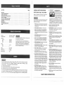
CAUT_©N:
Before using this Belt / Disc Sander,
read this manuai and follow
all its Safety Rubs and
Operating _nstructions,
Safety Instructions
_nstallation
Operation
Maintenance
Parts List
Espa_oi
1 °81@°848=1882
Sears,
Roebuck
Part No, 1372t5360001
and Co_ Hoffman
Estates_
_L (}0!79
USA
SECTION
PAGE
Warranty ..................................................................
Product Specifications .......................................................
Safety Rnstructions ..........................................................
Accessories and Attachments .................................................
Carton Contents ............................................................
Know your Belt ! D]sc Sander ..................................................
AssembJy and Adjustments
...................................................
Operation
.................................................................
Maintenance
.................................................
Troubleshooting
Guide
......................................................
Parts .....................................................................
MOTOR .................
HORSEPOWER ...........
2
2
3
6
6
, ............
7
8
14
16
17
18
BEFORE
3450 RPM
1760 FPM
2800 RPM
SIZES:
BELT ................
DISC ................
4" X 36"
6"
TABLE ..................
TABLE TILT ..............
BELT ARM TILT ...........
MITER GAUGE ...........
DISC / BELT
0 ° TO 45°
0 ° TO 90°
YES
Your bench belt/disc sander is wired at the factory for
120V operation. Connect to a 120V, 15 amp branch circuit
and use a 15 amp time delay fuse or circuit breaker. To
avoid shock or fire, replace power cord immediately if it is
worn, cut or damaged in any way.
Some dust created by power sanding, sawing, grinding, drilling, and other construction
contains chemicals
known [to the State of California]
to cause cancer, birth defects
reproductive
harm.
Some examples of these chemicals are:
¢ Lead from lead-based
paints.
activities
or other
¢ Crystalline silica from bricks, cement and other masonry products.
€ Arsenic and chromium from chemically4reated
lumber.
Your risk from these exposures varies, depending on how often you do this type of work. To reduce
SANDER
To avoid mistakes that could cause serious injury, do not
ptug the belt / disc sander in until you have read and
understood the following:
READ and become familiar with this entire instruction
manual. LEARN the tool's applications, limitations, and
possible hazards.
1.
2_
KEEP GUARDS IN PLACE and in working order.
3.
REMOVE ADJUSTING KEYS AND WRENCHES,
Form the habit of checking to see that keys and
adjusting wrenches are removed from the tool before
turning ON.
.
To avoid electrical hazards, fire hazards, or damage to the
tool, use proper circuit protection.
USING THE BELT/DISC
Safety is a combination of common sense, staying alert
and knowing how to use your belt / disc sander.
120',/, 60 HZ, 4.2 AMPS
2/3 (Max. Developed)
SPEEDS:
MOTOR ..............
BELT ................
DISC ................
t2.
GENERAL SAFETY INSTRUCTIONS
.
14. SECURE WORK. Use clamps or a vise to hold work
when practical. It's safer than using your hand and it
frees both hands to operate tool.
15. DISCONNECT TOOLS before servicing, and when
changing accessories, such as blades, bits, cutters,
and the like.
KEEP WORK AREA CLEAN. Cluttered areas and
benches invite accidents.
16, REDUCE THE RISK OF UNINTENTIONAL STARTING.
Make sure the switch is in OFF position before
plugging in.
17. USE RECOMMENDED ACCESSORIES. Consult the
owner's manual for the recommended accessories.
The use of improper accessories may cause risk of
injury to persons.
KEEP CHILDREN AWAY, All visitors should be kept at
a safe distance from the work area.
7,
MAKE WORKSHOP KID PROOF with padlocks, master
switches, or by removing starter keys.
8.
DON'T FORCE THETOOL. It will do the job better
and safer at the rate for which it was designed.
9.
USE THE RIGHTTOOL, Don't force tool or the
attachment to do a job for which it was not designed.
ALWAYS WEAR EYE
PROTECTION. Any belt / disc
sander can throw foreign
objects into the eyes which
could cause permanent eye
damage. ALWAYS wear Safety
Goggles (not glasses) that
comply with ANSI safety standard Z87.1. Everyday
eyeglasses have only impact-resistant lenses, They
ARE NOT safety glasses. Safety Goggles are available
at Sears. NOTE: Glasses or goggles not in compliance
with ANSt Z87.1 could seriously hurt you when they break.
13. WEAR A FACE MASK OR DUST MASK.
Sanding operation produces dust,
DON'T USE IN A DANGEROUS ENVIRONMENT.
Don't use power tools in damp or wet locations, or
expose them to rain. Keep work area well lighted.
6_
w_A_ Your
18. NEVER STAND ON TOOL. Serious injury could occur
if the tool is tipped or if the cutting toot is unintentionally
contacted.
19. CHECK FOR DAMAGED PARTS. Before further use of
the tool, a guard or other part that is damaged should
be carefully checked to determine that it wilt operate
properly and perform its intended function. Check for
alignment of moving parts, binding of moving parts,
breakage of parts, mounting, and any other conditions
that may affect its operation. A guard or other part that
is damaged should be properly repaired or replaced.
I0. USE PROPER EXTENSION CORD. Make sure your
extension cord is in good condition. When using an
extension cord, be sure to use one heavy enough to
carry the current your product will draw. An undersized
cord will cause a drop in line voltage resulting in loss
of power and overheating. The table on page 5 shows
the correct size to use depending on cord length and
nameplate ampere rating. If in doubt, use the next
heavier gauge. The smaller the gauge number, the
heavier the cord.
20. NEVER LEAVE TOOL RUNNING UNATTENDED,
TURN THE POWER OFF. Don't leave the tool until
it comes to a complete stop.
2t. DON'T OVERREACH.
balance at all times.
11. WEAR PROPER APPAREL. DO NOT wear loose
clothing, gloves, neckties, rings, bracelets, or other
jewelry which may get caught in moving parts.
Nonslip footwear is recommended. Wear protective
hair covering to contain long hair.
Keep proper footing and
22. MAINTAIN TOOLS WITH CARE. Keep tools sharp
and clean for best and safest performance. Follow
instructions for lubricating and changing accessories,
23. DO NOT use power tools in the presence of flammable
liquids or gases.
your exposure to these chemicals:work
in a well ventilated area, and work with approved safety
equipment, such as those dust masks that are specially designed to filter out microscopic particles.
SAVE THESE INSTRUCT ONS
3
24. DONOToperate
thetoo!ifyouareundertheinfluence 12.ALWAYS
maintaina minirnum
clearance
of 1/16inch
ofanydrugs,alcoholo1"medication
thatcouldaffect
or lessbetweenthetableorbackstop
andthesanding
yourabilityto usethetoolproperiy,
beltor disc.
25. Dustgenerated
fromcertainmaterialscanbe
hazardous to your health. Atways operate the
belt/disc sander in a well-ventilated area and provide
for proper dust removal. Use dust collection systems
whenever possible.
SPECHF C SAFETY NSTRL CTIONS
FOR BELT / DISC bANDERs'
- " "
For your own safety, do not try to use your belt/disc sander
or plug it in until it is comple[ely assembled and installed
according to the instructions, and until you have read and
understood this instruction manual:
.
THiS SANDER tS DESIGNED TO SAND WOOD OR
WOOD-LIKE PRODUCTS ONLY. Sanding or grinding
other materials could result in fire, injury or damage to
workpiece.
USE sander on horizontal surfaces only. Operating
the sander when mounted on nonqqerizontal surfaces
might result in motor damage.
2,
TO STOP i[ from tipping over or moving when in use,
the sander must be securely fastened to a bench top
or supporting surface.
,
5.
.
PLACE the sander so neither the user nor bystanders
are forced to stand in line with the abrasive belt or disc.
MAKE SURE the sanding belt is installed in the correct
direction. See directional arrow on back of belt.
ALWAYS have the tracking adjusted properly so the
belt does not run off the pulleys.
DO NOT USE sanding belts or discs that are damaged,
torn, loose. Use only correct size sanding belt and disc.
Narrower belts uncover parts that could trap fingers.
7_
,
9.
MAKE SURE there are no nails or foreign objects in
the part of the workpiece to be sanded.
ALWAYS HOLD the workpiece firmly when sanding•
Keep hands away from sanding belt or disc. Sand
only one workpiece at a time.
10. ALWAYS HOLD the workpiece firmly on the table
when using the disc sander and when using the belt
sander.
-13. DO NOT sand pieces of material that are too small to
be safely supported.
!4.. KEEP fingers away [rom where the belt goes into the
dusl trap.
15. WHEN sanding a large workpiece, provide additional
support at table height.
16. DO NO'[' sand with the workpiece unsupported.
Support the workpiece with the backstop or table. The
only exception is curved work performed on the outer
sanding drum. Plan your work support
17. NEVER USE ANOTHER PERSON as additional
support for a workpiece longer or wider than the table.
i8.
ALWAYS remove scrap pieces and other objects from
the table, backstop or belt before turning the sander
ON.
19. NEVER perform layout, assembly or set-up work on the
table while the sander is operating.
20. NEVER use solvents Io clean plastic parts. Solvents
coutd dissolve or other wise damage the material. Use
only a soft damp cloth to clean plastic parts.
21. SHOULD any part of your sander be missing, damaged,
or fai! in any way, or any electrical components fail to
perform proper!y, shut off switch and remove plug from
power supply outlet. Replace missing, damaged or
failed parts before resuming operation.
22. NEVER PULL°THE POWER CORD out of the receptacle.
Keep cords away from heat, oil and sharp edges.
23. HAVE AN ELECTRiCiAN REPLACE OR REPAIR
damaged or worn cords immediately.
24. When using the bett to grind or sharpen metal or
plastic material:
o DO NOT wet grind or polish. Never use a steady
stream of water on the workpiece. Dip or quench
the workpiece in water Io cool it.
o DO NOT OVERHEATTHE WORKP_BCE. Move
meta the material across the abrasive and al!ow
it to coo} when it becomes hot.
o DO NOT grind or pol •s_3 magnestum. It could
CATCH on fire.
11. ALWAYS SAND ON THE DOWNWARD S_DE of the
sanding disc when using the disc sander. Sanding on
the upward side of the disc could cause the workpiece
to fly out of position, resuking in injury.
SAVE THESE
NSTRUCT ONS
GROUNDING
DNSTRUCTIONS
IN THE EVENT OF A MALFUNCTmON OR BREAKDOWN,
grounding provides a path of least resistance for electric
current and reduces the risk of electric shock. This tool is
equipped with an electric cord that has an equipment
grounding conductor and a grounding plug. The plug
MUST be plugged into a matching receptacle thai is
properly installed and grounded in accordance with ALL
local codes and ordinances.
DO NOT MODIFYTHE PLUG PROVIDED. If it will not fit the
receptacle, have the proper receptacle installed by a
qualified electrician.
IMPROPER CONNECTION of the equipment grounding
conductor can result in risk of electric shock. The
conductor with the green insulation (with or without yellow
stripes) is the equipment grounding conductor. If repair or
replacement of the electric cord or plug is necessary, DO
NOT connect the equipment grounding conductor to a live
terminal.
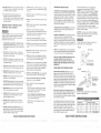
This tool is intended for use on a circuit that has a
receptacle like the one illustrated in FIGURE A.
FIGURE A shows a 3-prong electrical plug and receptacle
that has a grounding conductor. If a properly grounded
receptacle is not available, an adapter (FIGURE B) can
be used to temporarily connect this plug to a 2-contact
ungrounded receptacle. The temporary adapter should be
used only until a properly grounded receptacle can be
installed by a qualified technician. The adapter (FAGURE B)
has a rigid lug extending from it that MUST be connected
loa permanent earth ground, such as a properly
grounded receptacle box. The Canadian Electrical Code
prohibits the use of adapters.
CAUTmON: In all cases, make certain the receptacle in
question is properly grounded. If you are not sure have a
certified electrician check the receptacle.
This belt / disc sander is for indoor use only. Do not
expose to rain or use in damp locations.
Fig, A
CHECK with a qualified electrician or service personnel if
you do not completely understand the grounding instructions,
or if you are not sure the tool is properly grounded.
3-Prong Plug
USE ONLY 3-W_RE EXTENS!ON CORDS THAT HAVE
3-PRONG GROUNDING PLUGS AND 3-POLE
RECEPTACLES THAT ACCEPT THE TOOL'S PLUG.
REPAIR OR REPLACE DAMAGED OR WORN CORD
IMMEDIATELY,
GUIDELINES
FOR EXTENSION
CORDS
._...,... Properly
Grounding
Prong
Grounded
3-Prong Receptacle
Fig. B
USE PROPER EXTENSION CORD. Make sure your
extension cord is in good condition. When using an
extension cord, be sure to use one heavy enough to carry
the current your product will draw. An undersized cord wilt
cause a drop in line voltage resulting in loss of power and
overheating. The table below shows the correct size to use
depending on cord length and nameplate ampere rating. If
in doubt, use the next heavier gauge. The smaller the gauge
number, the heavier the cord.
Be sure your extension cord is properly wired and in
good condition. Always replace a damaged extension cord
or have it repaired by a qualified person before using it.
Protect your extension cords from sharp objects, excessive
heat and damp or wet areas.
Use a separate electrical circuit for your tools. This circuit
must not be less than #!2 wire and should be protected
with a 15 Amp time lag fuse. Before connecting the motor to
the power line, make sure the switch is in the OFF
position and the electric current is rated the same as the
current stamped on the motor nameplate. Running at a
lower voltage will damage the motor.
SAVETHESE
Grounding Lug _
I
is Connected to a
Known Ground
ake Sure This
2-Prong
Receptacle
This tool must be grounded while in use to protect the
operator from electrical shock.
{when using 120 voits only)
_.mpe:e,_e_!qg
more than
not more _hal;
Totallength of cord in feet
25'
50'
100'
150'
0
6
18
16
16
14
6
10
18
16
14
i2
t0
t2
16
16
14
12
12
16
14
12
Notrecommended
NSTRUCT ONS
,,
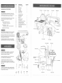
_EM
A.
B.
C.
D.
E.
R
G.
AVAHLABLE ACCES._ ,OR ES
Use only accessories recommended for this belt / disc
sander. Follow instructions that accompany accessories.
Use ol improper accessories may cause hazards.
DESCRiPTiON
Belt / Disc Sander
Disc
Disc housing
Disc table
k/liter gauge
Disc dust chute
Belt dust chute
Loose parts in bag:
"Fable support rod
Belt backstop
Hex key
Open-end wrench
Hex head bolt
Long pan head screw 40mm
Pan head short screws
Pan head thin screws 1/2"
Pan head medium screws 12ram
Large washer
Small washers
H,
I.
J.
K.
L.
M.
N.
O.
R
Q.
R.
Visit your Sears Hardware Department or see the Sears
Power and Hand Tool Catalog for the following
accessories:
o Adhesive-backed Discs 6 inch:
Fine, Medium, or Coarse Griics
o Sanding Belts 4 x 36 inch:
Fine, Medium, Coarse, or Extra Coarse Grits
_QUANTITY
1
1
1
1
1
1
1
Sanding disc
\
Disc housing
Back stop
Tension lever
1
1
1
1
t
1
2
2
1
1
2
Sanding belt
Idler drum
Bett tracking knob
o Abrasive Disc & Belt cleaner
Table assembly
stop
Use only accessories designed for this belt / disc sander to
avoid injury from thrown broken parts or workpieces.
Mounting hole
Sears may recommend other accessories not listed in this
manual. See your nearest Sears store or Power and Hand
Tool Catalog for other accessories.
Do not use any accessory unless you have completely
read the instruction or owner's manual for that accessory.
Disc dust chute
On/Off switch
Hex key _tor_ge
Miter gauge
B
c
If any part is missing or damaged, do not plug the belt /
disc sander in until the missing or damaged part is
replaced, and assembly is complete.
Carefully unpack the belt / disc sander and all its parts,
and compare against the illustration below.
To protect the belt / disc sander from moisture, a
protective coating has been applied to the machined
surfaces. Remove this coating with a soft cloth moistened
with WD-40.
Bevel scale
G
To avoid fire or toxic reaction, never use gasoline, naphtha,
acetone, lacquer thinner or similar highly volatile solvents
to clean the belt / disc sander.
H
I
L
J
M
Table support rod
@
N
6
:::
O
:
::
@@
Q
:
:
Table
Iock knob
R
: :::
::: : ;:::::::::::
:
: :
:
:: ::,::: ::
:::
7
:!'
::_
:i
ASSEMBLY
INSTRUCTIONS
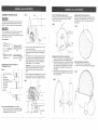
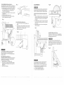
PULLEY COVER INSTALLATION (FIG. E)
Attach pulley cover (1) using the 40mm long pan head
screw (2) and 12mm pan head screw (3), as shown.
Tighten screws securely.
To avoid injury, always keep the plug disconnected from
the power source and the switch turned OFF until the
sander is completely assembled and adjusted properly.
Fig. E
_
3
Fig. G
i
For your own safety, never connect plug to power source
outlet until all assembly and adjustment steps are
completed, and you have read and understood the safety
and operating instructions.
SANDING DiSC iNSTALLATION (FIG. G)
Remove and clean any adhesive or material left on the
disc plate (2). Peel plastic backing from abrasive disc (1)
and carefully press disc firmly in position around the
sanding disc.
©
TOOLS NEEDED
Slotted screwdriver
2.
Level
Phillips screwdriver
3.
4.
Combination
Adjustable wrench
square
MOUNTING BELT AND DISC SANDER TO
WORKBENCH (FIG. B)
IMPORTANT: Do not over tighten belt tension because
it does not require excessive tension to function
properly• Excessive tension will reduce motor and
belt life.
Fig. B
2
1.
2.
belt / disc sander base
Bolt
3......._"'f_
4
3.
4.
5.
Flat washer
Rubber washer
1/2" Foam pad (optional)
/
1 mUm
[
7.
6.
8.
9.
10.
Flat washer
Worksurface
Lockwasher
Hex nut
Jam nut
Loosen lock nut (3), and belt tension set screw (4) by
turning it counterclockwise.
Raise up on the motor pulley (5) to replace or remove
the existing belt. Place new belt (6) on both pulleys (5)
and (7)•
At the center span of the pulleys, apply light pressure
to the belt. At the same time tighten set screw (4) by
turning it clockwise, until the belt is just stretched.
Reapply light pressure to the belt and maintain belt
tension between t/4" to !/2" deflection.
5,
r i .......
I I
i i
Fig, D
t
(
After correct tension is obtained tighten lock nut (3), and
position sanding arm (2) in the horizontal position by
loosening the two hex screws (1). Retighten hex screws•
SANDING DiSC PLATE INSTALLATION (FIG. F)
,_ '<
1. Thread 1/4" set screw (1), into the tapped hole on hub
of sanding disc plate (2). Turn clockwise to tighten.
2. Slide sanding disc plate (2), on drive shaft (3) making
DISC COVER INSTALLATION (FIG. H)
sure flat on drive shaft is aligned with set screw (1) in
1. Position disc cover (1) in place as shown.
hub of disc plate (2). Stide disc plate onto shaft until
2. Insert the two 1/2" pan head screws (2) and tighten.
disc plate surface and edge of the pulley cover are
nearly flush.
3. Insert hex wrench, down through slot (4) in the top of
belt and pulley guard and tighten set screw (I) against
flat on drive shaft (3).
4
1
J-
i
5
7
......
t0
6
2
PULLEY BELT ADJUSTMENT (FIG. C AND D)
1. Loosen the two hex screws (1) with wrench provided,
and move the sanding arm (2) to the vertical position.
Then tighten the two screws. (Fig. C)
5
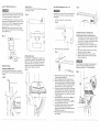
TABLE ASSEMBLY INSTALLATION (FIG. I)
The worktable can be used with either the sanding disc or
the sanding belt. It should be used to support workpieces
in all sanding operations except inside curve applications.
1. Insert the table support rod (1) into the sander base
hole as shown. Table support rod should extend
5" outside of the sander base.
2.
3.
4.
ADJUSTMENTS
Fig. J
To avoid injury, always keep the plug disconnected from
the power source and the switch turned OFF until the
sander is completely assembled and adjusted properly.
Align round side of the support rod (1) with hex bolt (2)
and tighten bolt.
Slide table assembly (3) onto rod (1).
Adjust table, align flat side of support rod with hex
boJt (4) on tabte bracket, and tighten.
Fig. U
DUST CHUTE _NSTALLATtON (RG. K)
1. Position the dust chute (1) on the sanding arm as
shown.
2. Place washers on two pan screws (2). insert the screws
through the slots on the side of the dust chute into the
threaded holes on the sanding arm (3).
3. Tighten screws securely.
ADJUSTRNG TABLE SQUARE WITH SANDING DiSC
(F_G. L)
1. Using a combination square (1), place one side of the
square on the table (2) with the other side against the
sanding disc (3), and check to see if the table is 900
to the disc.
2. if the table surface is not 90 ° to the disc, loosen table
lock knob (4), adjust table square with disc and tighten
iock knob (4).
3. Adjust pointer (5) to the 0G mark on [he angle scale,
using a screwdriver.
Fig. L
Fig. K
ADJUSTING TABLE ANGLE (FIG. N)
The table can be tilted [rom 0° to 45 ° by loosening the
tabte lock knob (1), tilting the table to the desired angle,
and tightening table lock knob (1).
FIIt
II
_ llf_I
After tilting the table, the table assembly must be
repositioned on the support rod to a maximum of 1/16"
distance between the sanding disc and the edge of the
table, to avoid trapping the work or fingers between the
disc and table.
Fig. N
To avoid trapping the workpiece or fingers between the
table and sanding disc, the table edge should be
positioned a maximum of 1/16" from sanding disc plate,
as shown in FIG. I.
4
O
BACK STOP INSTALLATION (FIG. J)
The backstop prevents the workpiece from being pulled or
dragged beyond the sanding arm. It should always be
used to help control the workpiece.
1. Position back stop (1) on sanding arm (2).
2, Place washer (3) on hex bolt (4). Insert bolt through
slotted hole into the threaded hole in the side of the
sanding arm.
& Tighten hex bolt securely.
:::
:
=i
::= :
:
i
:
To avoid trapping the workpiece or fingers between the
table and sanding disc, the table edge should be
positioned a maximum of 1/16" from sanding disc plate.
ADJUSTING TABLE TO BE HORIZONTAL
1. Place level on table parallel to disc.
2. If not level, hold table, loosen bolt (1).
3. Adjust to horizontal and retighten bolt.
t0
=
:
:: ::
=:
L': :
i-_ib:
:
<: ¸
:::.
:
-i
!
/
(FIG. I_A)
?
....
1t
....
SAFETY POWER SWITCH (FIG. O)
WRENCH (F1G. Q)
Insert the handle of the wrench into the metal clip located
on the sander as shown.
To avoid injury, always keep the plug disconnected from
the power source and switch turned OFF until the sander
is completely assembled and adjusted properly.
Fig. U
To avoid injury, turn switch OFF and disconnect the plug
from the power source before removing and installing
sanding belts.
Fig, Q
The ON-OFF toggle switch (1) is located on side of the
sanding machine. Pull toggle switch up to turn the tool ON
and down to turn it OFR The toggle switch has a switch
key (2) for locking the switch in the OFF position.
REPLACmNG SANDING BELT (FIG. S, T, U)
1.
Remove two screws (1), and dust chute (2).
Fig, S
f
IMPORTANT: When removing switch key from toggle
switch, always push the switch down to the OFF position
and pull yellow key out.
CHANGING POSITION OF SANDING ARM
Fig. 0
o
©
2.
Remove hex bolt (3), and backstop (4)•
SANDING ARM IN VERTICAL POSITION (FIG. V)
1. The sanding arm can be used in either the horizontal
or vertical position. To move the sanding arm, loosen
the two bolts (1), that attach arm (2). Move the arm to
the desired position. Tighten the two bolts.
2. Insert the table support rod (3) into auxiliary hole as
shown. Table support rod should extend 5" outside
base.
3.
Fig. T
3
4
MITER GAUGE (FIG. R)
A miter gauge (1) is supplied with your sander and is
used with the disc table. The miter gauge body can be
tilted 0 ° to 45 ° right or left for angle or miter sanding.
Install the slide rod into the table slot (2) as shown.
Loosen lock knob (3), rotate miter gauge body to the
desired angte and tighten lock knob (3),
WRENCH STORAGE
1/8 INCH HEX WRENCH (FIG. P)
Insert the long end of the hex wrench (1) through the
holes (2) located on the back surface of the pulley cover,
as shown.
4.
5.
Align round on support rod with hex bolt on sander
and tighten hex bolt (4) on sander.
Slide table assembly (5) onto rod (3), as shown.
Align flat on support rod with hex bolt (6) on table
bracket and tighten bolt.
To avoid trapping the workpiece or fingers between the
table and sanding belt, the table edge should be
positioned a maximum of 1/16" from sanding belt.
Fig, R
Fig. V
1
3
3.
Slide tension lever (5), to the right to release tension
on the sanding belt (6) (Fig, U),
4. Remove sanding belt from both sanding drums (7).
5. Slide new sanding belt over sanding drums, making
sure the belt arrow located on the inside of the belt will
run in the direction of the arrow on the sander• Slide
tension lever (5), to the left to apply belt tension.
6, Quickly push the belt forward by hand (in the direction
of the belt rotation arrow, visible from the top between
the sanding disc and the belt arm) and check to see if
the sanding belt tends to run to one side or the other
on the two pulleys.
7. If the sanding belt runs toward the disc, slightly turn
the tracking knob (8) counterclockwise.
8. If the sanding belt runs away from the disc, slightly
turn the tracking knob (8) clockwise.
9. Plug sander into power source and turn the switch
ON and OFF quickly, and check to see if the
sanding belt runs to either side. Readjust and fine tune
tracking knob if necessary.
10. When proper tracking is achieved, replace backstop
and dust guard.
Fig. P
6
12
:
:
13 i_?!_!_;_i_iYF_!!!_!;_J:_!!_!!_i!_!_!i!i!:_i_!:!i_!_:!!_i_?:i_ii!_!_!_!;_i_:_!!i_!_
!
ADJUSTING
SANDINGARM
LEVELING
THEARM(FIG.W)
A positivestopis provided
to positionthesandingarm
levelwiththeworkbench
whenthe armis inthe
horizontal
position.
1. Placethesandingarm(1) inthe horizontal
position.
2. Placea level(2)onthesandingbeltandchecktosee
if thearmis level.
3. If anadjustment
is necessary,
loosenlocknut(3),and
turnsandingarmstop(4)clockwise
toraise,or
counterclockwise
to lower,untilthesandingarmis
level.Thentightenlocknut(3).
Fig. W
SANDING
Freehand
idler drum
workpiece
The belt and disc sander is designed to perform rough
sanding operations on surface, edge grain and end grain
sanding. The sander will also perform freehand forming
and contouring operations. The following suggestions are
recommended for best results and safest use.
1
To avoid injury, do not apply the end of the workpiece to
the idler drum. This could cause the workpiece to fly up
or cause kickback.
Fig. Y
1.
2.
2
INSIDE CURVES (FIG. Y}
sanding of inside curves can be sanded on the
(1). Never attempt to sand the ends of a
on the drive drum.
3,
Always apply light pressure allowing the abrasive to
remove the material slowly.
The workpiece should be moved, continuously, to
avoid burning.
Avoid sanding small pieces of wood which will
position the fingers close to the abrasive belt or disc.
USING BACKSTOP WITH SANDING ARIVl (FIG. X)
When using the sanding arm in the horizontal position, to
perform surface or edge sanding, the backstop (1) must
always be used. Always hold the work piece (2) firmly
keeping your fingers away from the sanding belt (3).
Always keep the end of the workpiece against the
backstop and move the work evenly across the sanding
belt. Apply only enough pressure to allow the sanding
belt to remove material, Use extra caution when sanding
very thin piece&
The edge of the backstop must be positioned a maximum
of 1/16" from the sanding belt to avoid trapping the work
or fingers between the backstop and sanding belt.
Fig. X
END GRAIN SANDING WITH THE BELT (FroG.AA)
When sanding the ends of the wide workpieces it is
more convenient to use the sanding belt (1) with the
sanding arm in the vertical position and the table
assembly (2) moved to the sanding belt, as shown. See
section titled CHANGING POSITION OF SANDING ARM.
For more accurate work use the miter gauge and move
the workpiece evenly across the sanding belt.
WMPORTANT: Use a combination square to position
miter gauge perpendicular to face of the disc. If it is not
square loosen miter gauge knob and move miter gauge,
slightly, until it is square.
For your own safety, turn switch OFF and remove plug
from the power source outlet during assembly or while
making adjustments to belt / disc sander.
The edge of the table must be positioned a maximum of
1/16" from the sanding belt to avoid trapping the
workpiece or fingers between the table and sanding belt.
Fig. AA
SANDING OUTSIDE CURVES (FroG.Z)
Freehand sanding of outside curves should be done on
the sanding disc (1). Keep fingers a minimum of 1 inch
from the disc.
Always sand on the left (downward) side of the sanding
disc, as shown. Sanding on the right (upward) side of the
sanding disc could cause the workpiece to fly up which
could be hazardous.
The edge of the table must be positioned a maximum of
1/16" from the sanding disc to avoid trapping the
workpiece or fingers between the table and sanding disc,
Fig. Z
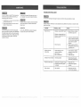
TROUBLESHOOTUNG
For your own safety, turn switch OFF and remove plug
from the power source outlet before maintaining, or
lubricating your belt / disc sander.
1.
2.
Frequently blow out or vacuum out any dust that may
accumulate inside the motor.
Remove impacted sawdust from the disc and belt
abrasive or replace abrasive.
Certain cleaning agents and solvents damage plastic
parts. Some of these are: gasoline, carbon tetrachioride,
chlorinated cleaning solvents, ammonia and household
detergents that contain ammonia. Avoiding use of these
and other types of cleaning agents, minimizes the
probability of damage.
GUIDE
To avoid shock or fire hazard, if the power cord is worn or
cut or damaged in any way, have it replaced immediately.
Turn switch OFF and always remove plug from power source before making any adjustments or repairs.
All repairs, electrical or mechanical, should be attempted
only by trained repairmen. Contact the nearest Sears
Service Center.
All repairs, electrical or mechanical, should be attempted only by qualified service technicians.
Sears Service Center.
LUBRaCATION
PROBLEM
PROBABLE
All of the BALL BEARINGS are packed with grease at
the factory. They require no further lubrication.
Motor will not run.
1, Defective or broken ON/OFF switch.
CAUSE
2. Defective or damaged switch cord.
3. Defective or damaged switch relay.
4. Burned out motor.
5. Blown house fuse.
Machine slows down
while sanding,
Contact the nearest
REMEDY
1-3. Replace all broken or defective
parts before using sander.
4,
.
Consult your local Sears Service
Center. Any attempt to repair this
motor may create a hazard unless
repair is done by a qualified
technician.
Replace house fuse. Turn OFF
other appliances and power tools
on the same circuit.
t. Operator applying too much
pressure to workpiece,
2. Dirt on wheels.
3. Worn or stretched belt.
1.
Sanding belt runs off pulleys.
1. Not tracking properly.
1.
Adjust tracking. See section
"REPLACING SANDING BELT".
Wood burns while sanding.
1. Sanding disc or belt glazed with sap.
2. Excessive pressure being applied
to workpiece.
1.
2.
Replace belt or disc.
Reduce pressure applied to
workpiece.
Motor overheats
1. Motor overload.
1.
Reduce motor load. Allow
2.
3.
Use less pressure in applying
workpiece to sanding surface.
Clean wheels.
Replace pulley belt.
to cool off before restarting.
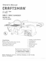
4" x 36"
4" x 36" BELT/DDSC
SANDER
When servicing use only CRAFTSMAN
product damage.
MODEL
BELT/DISC
SANDER
MODEL
Nee 137.215360
replacement parts. Use of any other parts may create a HAZARD or cause
Any attempt to repair or replace electrical parts on this belt / disc sander may create a HAZARD unless repair is
done by a qualified service technician, Repair service is available at your nearest Sears Service Center.
Always order by PART NUMBER, not by key number
Key No.
Part No.
Description
Size
Qty,
Key No,
Part No.
Description
Size
Qty.
1
2
3
4
5
6
7
8
9
I0
2668BBDA37
15900204
2601BZDA47
2701FZDt06
15904102
8343725904
15900702
2570BBN207
15900904
2898DB7G06
Pan hd. screw
Floor p{ate
Hex. hd. boll
Hex nut
Motor pulley
Motor
Motor rod
E-ring
Base
Rocker switch
M6x1,0-8
4
1
1
'1
1
t
1
t
1
1
81
62
63
64
65
66
67
68
69
70
270tQBD514
N/A
16001701
15902001
2705QZB506
2601QBD K37
2502NBC406
16003001
16002901
15902501
Hex. nut
t/2x13
1
Spring
Guide drum
Nut chuck
Hex, hd, boil
Spring washer
Grips
Belt tension lever
Handle
tI
12
13
14
15
16
17
18
19
20
2652PBCK1 t
15901204
2852PSCK10
2504MZCO04
15903101
2801UBHA07
t 5901704
2668BBDA37
15901903
26010BDK57
Pan hd. tapping screw
Switch cover
Pan hd. tapping screw
External tooth lock washer
Switch box
Strain relief
Label
Pan hd. screw
Plate cover
Hex. hd, bolt
M4xl 8q 2
2
1
2
2
1
2
1
4
1
1
71
72
73
74
75
76
77
78
79
80
15904001
2501NBDN16
16002301
1590170t
2570BBNt 12
2506MBN612
1590I 801
15901902
15902101
15900801
Plastic wasl_er
Fiat washer
Spring
Rubber pad
C-ring
Wave washer
Bush
Drum4d[er
Shaft-idler
Sanding bell
21
22
23
24
25
26
27
28
29
36
2603BBLA38
15902202
2888BBDA37
2807BY06H2
2606BBLA05
2701 FBD106
2669SBDA41
2668QBDK17
1771150l
15904601
Hex. soc. set screw
Plate cover
Pan hd. screw
Power cable
Hex. ace. set screw
Hex, nut
Pan hd. screw
Pan hd. screw
Disc cover
Disc sanding
M6xl _0-t 0
1
!
4
1
2
1
1
2
1
1
8!
82
83
84
85
86
87
88
89
90
15905501
2501QBDK53
2501NBDN24
16005201
2668QBDK24
16004901
26010BDK55
16004801
15908101
2504MB0005
Lock kr)ob
Hex. hd. boil
Flat washer
Tilt bracket
Pan hd. screw
Needle pointer
Hex. hd. bolt
Tabte support
Hex. soc. hd. cap bolt
External tooth lock washer
31
32
33
34
35
36
37
38
39
40
15904501
2603RBLK32
2668BBDA45
16005903
2138NBL701
2572ARY150
15903701
26010BDK59
2501NBDN22
15904002
Hate sanding
Hex, soc. set screw
Pan hd. screw
Pulley cover
Wrench hex.
Synch belt
Spindle pulley
Hex. hd. boil
Ftat washer
Bearing seat bracket
I
I
I
1
1
1
1
2
2
I
9I
92
93
94
95
96
97
98
99
100
2501NBDNO3
15906301
16004301
15906001
15905301
14911703
14606001
2641BZDA22
14607802
2501NZDN10
Flat washer
Pin pivot sapport
Pin pivot
7ab}e sander
Support rod
Sheet bar
Angle pointer
Round washer hd. screw
Miter gauge
Flat washer
41
42
43
44
45
46
47
48
49
50
2502ABC416
2602BBLA55
15907803
2669QBDK27
17305801
2001ZZ6001
2570BBN1 !2
15900102
2603RBLK32
18001203
Spring washer
Hex. sec. hd. cap belt
Caution Iabei
Pan hd. screw
Bearing seat
Ball bearing
C-ring
Drive-drum
Hex. soc. set screw
Table belt
2
2
1
3
1
2
2
1
2
1
t01
t02
103
104
105
106
107
108
109
110
14608301
14608001
15910601
2620BBDC19
1591080I
t5911004
2669BBDA39
2805U5HN18
2801DBHAOI
2606BBLA05
Knob
Pin
Wrench
Pan hd. screw & washer
C_amp
Warning label
Pan hd. screw
Terminat
Strain relief
Hex. soc. set screw
51
52
53
54
55
56
57
58
59
60
15906701
16001401
2668QBDK22
16008101
250tNBDN03
26680BDK22
2601QBDK34
2501NBDN16
16003101
15901101
Drive shaft
Cap.-beari ng
Pan hd. screw
Dust collector
Flat washer
Pan hd. screw
Hex. h& belt
Fiat washer
Stop back
Screw stop
1
1
8
!
2
2
t
1
1
1
111
112
113
114
28605BH071
163t 4801
264t BBDA40
250t MZDN06
137215360001
Switch key
Power cord cl amp
Round washer hd. screw
Hal washer
Owner's manual
N/A
Not applicable
Not shown
M6xl.0
M6xl.0
M4xt 8-8
M6x1.0-8
5/16xt8,1
M6x1,0-8
M4x&7-4
M6xl.0
M6xt.O-20
8#x32qi2
1/4x20-1/4
M6x1,0-40
5t16x18-1 1/2
5/16x25/32-1/8
M8xl,25-20
10#x24-3/4
t/4x20-ti4
10#x24-I/4
I0#x24-1/4
l/4x20-1/2
1/4x3/4-1/16
to
t
t
1
1
1
I
1
1
1/4x20
"1/4x20
1
1
1
2
2
1
2
1
1
1
1
1
1
1
1
1
1
1
2
2
5/16x18-7/16
10#x24-I/4
5/16x18-3/4
10#x32-0.59
'_
M5x0.8-6
M6x1.0-12
M6xl.0-12
M4x0.7-4
co
©
o
2
2
2
I
1
1
1
1
1
1
I
1
1
2
1
1
1
1
1
2
I
2
2
2
1
19
NO. 137.215360