1
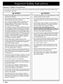
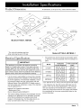
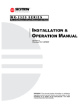
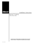
Installation
Millennia
® Electric
Instructions
Cooktop
For use with models ETT304-1, ETT365-2, MET304 and METB365-1
TESTED IN ACCORDANCE WITH THE LATEST EDITION OF ANSI Z21.1 AND
U.L. 858 STANDARD FOR HOUSEHOLD COOKING APPLIANCES.
Part No. 65170
Rev. d
Before You Begin ..............................................................
Important Safety Instructions ..........................................
Important Information About Safety Instructions ..............
Safety Symbols and Labels .............................................
General Safety Precautions .............................................
Installation Specifications ................................................
Product Dimensions .........................................................
Electrical Specifications ...................................................
1
1
1
1
2
3
3
3
Planning the Location ......................................................
Cabinet Layout .................................................................
Installation Instructions ....................................................
Chassis Installation ..........................................................
Verify the Package Contents ............................................
Electrical Connection .......................................................
Verifying Proper Operation ...............................................
If You Need Help...
Product Data Label
If you have questions or problems with installation, contact
your Dacor dealer or the Dacor Customer Service Team.
For repairs to Dacor appliances under warranty call the
Dacor Distinctive Service line. When you call, have the
model and serial number of the appliance ready. The model
and serial number are printed on the product data label.
•
The product data label contains the model and serial
number information and the electrical requirements.
•
It is located on the bottom of the cooktop chassis.
Dacor Customer Service Team
Phone:
(800) 793-0093 (U.S.A. and Canada)
Monday -- Friday 6:00 A.M.to 5:00 P.M.Pacific Time
Web site:
www.Dacor.com
Dacor Distinctive Service (for repairs under warranty)
Phone:
(877) 337-3226 (U.S.A. and Canada
Monday -- Friday 6:00 A.M.to 4:00 P.M.Pacific Time
All specifications
are subject to change without notice. Dacor ®assumes no liability for changes to specifications.
© 2007 Dacor, all rights reserved.
4
4
6
6
6
6
8
Important:
•
Installer: In the interest of safety and to minimize problems, read these installation instructions completely and carefully before you begin the installation process. Leave these installation instructions with the customer.
•
Customer:
Keep these installation instructions for future reference and the local electrical inspector's use.
Important Information About
Safety Instructions
_DANGER
IMPORTANT: DOnot store or use c0mbustiblel
•
The Important Safety Instructions
and warnings in
this manual are not meant to cover all possible problems and conditions that can occur. Use common
sense and caution when installing, maintaining or operating this or any other appliance.
•
Always contact the Dacor Customer Service Team
about problems and conditions that you don't understand. See Customer Service Information.
flamma.
ble or explosive vapors and liquids (such as gasoline)on
or in the vicinity of this or any other appliance. Also keep
items that could explodel such as aerosol cans, away
from the c0oktop. DO not store flammable or explosive
atedals in adjacent cabinets or areas (including above
and below the cooktop).
[_
WARNING
I
WARNING.
NEVER use this appliance as a space
heater to heat or Warm the rooml D0ing so may result in
Safety Symbols and Labels
I
overheating of the appliance.
DANGER
[_
Immediate hazards that WILL result in severe personal
I
WARNING
I
WARNING ' NEVER cover anY Vents, slots, holes or
passages on the cookto p chassis, Doing so blocks air
njury or death ...........................
I
I
flow through the cooktop and may cause a fire hazard1
[_
I
WARNING
[_
Hazards or Unsafe practices that COULD result in severe
personal injury or death.
WARNING
I
Do not install this appliance outdoors andi0r near Watefl
for examp el near a pool
CAUTION
Hazards or Unsafe practice s that COULD result in
personal injury or property damage.
I
READ AND SAVE THESE INSTRUCTIONS
_=lc'clr_
1
General Safety Precautions
To reduce the risk of fire, electric shock, serious injury or death when using your appliance, follow basic safety precautions, including the following:
WARNING
'
Read the accompanying use and care manual before
operating this appliancel
Keep'
i
packaging materials away from children:Plastic
sheets and bags can cause suffocationl
,
If you receive a damaged PrOduct, immediately co ntact your dealer or builder. D0not install cruse a
damaged appliancel Do not install cruse the appli-
WARNING
•
To avoid a fire hazard, do not hang flammable or heat
sensitive objects over the cooktop.
•
Do not place anything other than cooking utensils on
top of the cooktop. Do not use the cooktop as a table
or shelf.
•
If the cooktop is near a window, do not use long curtains as window treatment. The curtains could blow
over the cooktop and create a fire hazard.
ance if the conduit is damaged!
•
DO NOT TOUCH THE SURFACES OF THE
COOKTOP DURING OR IMMEDIATELY AFTER USE.
After use. make sure these surfaces have had sufficient time to cool before touching them.
•
Do not wear loose or hanging apparel while using the
cooktop. Do not allow clothing to come into contact
with hot surfaces and the surrounding areas during
and immediately after use.
•
Do not heat unopened food containers such as baby
food jars and cans or eggs. Pressure build up may
cause the container to burst and cause injury.
•
Do not allow pans to boil dry.
Before performing any type of service or installati0n
make sure that power t0 the applianCe is turned off at
the circuit breaker panel or fuse box.
•
Do not store plastic or other utensils with low melting temperatures in drawers immediately below the
cooktop.
Only use the cooktoP for cooking tasks expected of a
home appliance as outlined in the literature accompa,
hying t: This cooktop is not intended for commercial
•
Clean the cooktop before using it for the first time
according to the use and care manual.
•
Non-stick coatings, when heated, can be harmful to
birds. Remove birds to a separate, well-ventilated
room during cooking.
This;
appliance must be properlY installed and groundL
edby a qualified installer according to these installa_
tion instructions Prior to use. The installer must show
the customer the location of the circuit breaker panel
or fuse box so that they know where and how to turn
off power to the co0ktop. Dacor is no t responsible for
the cost of correcting PrOblems caused by improper
installation, The owner is responsible to make sure
'
'i
this appliance is properly installed:
D0 not install, repa ror replace any part of the
Cookt0P unless specifically recommended in the literai
ture accompanying it. A qualified service technician
must perform all other servicel
or industrial Usel
' D0not
use €ori0sive chemicals or Vapors 0n °rin the
VicinitY of this appliancel Clean this appliance 0nly in
the
manner specified in the use and care manual.
;
D0 n0t climb on any part of the appliancel
'
not leave Children 0r pets a One or unattended in
the area around the cooktoPl Donot allow children to
play with the controls.
;' DO n0t Store items Of interest to children above or
on top of the cookt0P. Children could be burned or
injured while climbing on the appliancel
•
Do not tamper with the controls. Do not adjust or alter
any part of the cooktop unless specifically instructed
to do so in this manual.
plastic and cloth away from hot surfaces. Do not put
such
items on the cooktop. Do not allow pot holders
to touch hot surfaces.
2
_mC_
Product Dimensions
A, tolerances: +1/16 (+1.6 mm), unless otherwise stated.
4" (102 mm)
Chassis height
30 1/4" *
(768 mm)
28 3/8"
21 1/4" *
(721 mm)
19 3/8"
(495 mm)
4" (t02 mm)
Chassis height
36 1/4" *
(921 mm)
jJ
(540 mm)
Models
ETT304-1,
MET304
34 3/8"
(873 mm)
_.
19 3/8"
21 1/4"*
(495 mm)..
(540 mm).
* For units with stainless steel trim,
other units may be up to 1/8" less
Electrical Specifications
[_
Models
•
It is the owner's responsibility to ensure that a licensed
electrician performs the installation of the electrical supply for this appliance. The electrical installation, including minimum supply wire size, must comply with the
National Electric Code ANSI/NFPA 70 (latest revision)
and local codes and ordinances. A copy of the standard
may be obtained from:
National Fire Protection Association
1 Batterymarch Park
Quincy, Massachusetts 02269-9101
METB365-1
The junction box and the remote circuit breaker panel
or fuse box, must be accessible when the cooktop is in
place.
IMPORTANT
This appliance is Pr0vided with electrical connection
leads in a flexible metal conduit: These leads may be a
sma!ler gage than the standard household Wiring of the
dedicated supply circuit, but they are suitable for connection to these circuits under the Jurisdiction of the National
Electric Code, andior the local inspection authority.
ETT365-2,
Model
Dedicated
Circuit
Required
Total Connected
Load**
ETT304-1
240 Vac, 60 Hz.
3 wire* 40 Amp.
6.9 kW
(29 Amp.)
ETT365-2
240 Vac, 60 Hz.
3 wire* 40 Amp.
9.1 kW
(38 Amp.)
MET304
240 Vac, 60 Hz.
3 wire* 40 Amp.
6.9 kW
(29 Amp.)
METB365-1
240 Vac, 60 Hz.
3 wire* 50 Amp.
9.6 kW
(40 Amp.)
Two 120 Vac hot 'L1 and L2) and one ground (all copper).
** For reference only. See the product data label (on the
bottom of the unit) for exact specifications. The minimum
wire size required by the manufacturer is 8 AWG. Local
codes may require that minimum wire gauge used exceed
this requirement for the power requirements listed on the
product data label.
The correct voltage, frequency and amperage must be
supplied to the appliance from a dedicated, grounded,
circuit that is protected by a properly sized circuit
breaker or time-delay fuse. If a time-delay fuse is utilized, fuse both sides of the line (L1 and L2).
_mCD_
3
Ventilation
WARNING
°
IMPORTANT: Observe all governing codes and ordinances during planning and installation. Contact your
local building department for further information.
°
To reduce the risk of a fire hazard, all minimum/maximum clearances shown must be met or exceeded.
°
When installing model ETT365-2 or METB365-1 and
the bottom of the chassis is to be enclosed wall to
wall, you must install ventilation duct kit ATD323. See
the duct installation instructions for cutout req uirements.
Planning the Location
•
Dacor recommends installing a non-combustible
rial on the rear wall behind the cooktop.
mate-
•
Carefully check the location where the cooktop is to be
installed. It should be placed for convenient access.
•
To reduce the risk of personal injury caused by reaching over a hot appliance, cabinet storage space located
directly above the cooktop should be avoided.
To reduce the risk of personal injury and to reduce accumulated smoke in the room, Dacor strongly recommends
installing a vent hood or raised vent. Install the vent hood
or raised vent according to the accompanying installation
instructions. A vent hood should cover the entire cooking
surface below it.
If installing the cooktop with a raised vent, install only the
following approved Dacor model numbers:
Cooktop
Models
Approved Raised Vent Models
ETT304-1 MET304
ERV30, PRV30 or RV30
ETT365-2 METB365-1
ERV36, PRV36 or RV36
Raised vent installation must allow room for the stiffener
bar on the back of the raised vent chassis. See below.
3/8" Min. (10 mm)
flat countertop overhang
. required behind cutout
Countertop
,,,
i /
Stiffener
\\
-blt
ETT or MET series
'_ql
Cabinet
II_[J
_'l
,l/
II
I/
IT
I
face
_'
"
3/8" Min. (10 mm) space
behind raised vent
',
',
chassis to clear stiffener
,,
II IL_ ERV
II
I
1i
/l ,
in
Make certain that electrical power meeting the specifications on page 3 can be provided in the selected
location. Verify that the electrical location is permitted
by local building codes. Locate the junction box within
reach of the included 48 inch long (1219 ram) cooktop
power conduit attached at the bottom right rear of the
chassis. Do not lengthen the wiring. Make sure the
underside of the cooktop and the junction box are
accessible for inspection and service.
7-'
cooktop
L ------
or PRV series
',
raised
',
i
',
to determine
]
.[_
vent: Check raised vent
dimensions/specifications
Cabinet Layout
proper fit
in
Floor
,,''
I I
Under Counter Clearance
Side View: Cooktop and ERV/PRV Series Raised Vent
Allow a minimum of six(6) inches (152 mm) clearance
between the base of the glass cooktop frame and any
combustible surface below, including the upper edge
of drawers below the cooktop. Proper under-cabinet
clearance is also required for the cooktop hold down
brackets.
5/8" Min. (16 mm)
countertop
', flat
required
behindoverhang
cutout
Count_rtop
\\
:/
Stiffener
,_%
' tl
t
•
ETT or MET series
i
cooktop
Cabinet
I
11
""
face
iJJn
--5/8" MIn.(16 mm) space "
'1
.r_
II behind raised vent
ii
t
A
Cooktop Models
6" (152 mm)
Min. clearance
to combustible
surfaces
A - Minimum Under Counter
i inchassis....
to clear stiffener
30 1/2" (775 mm)
ETT365-2, METB365-1
36 1/2" (927 mm)
i!
I
U_ RV series raised vent:
I1
I
raised vent
dimensions/specifications
,,
',',
i li Check
I /I
II
•
to determine
"'
,
i
proper fit
i
II
i
i
i
I
I
I
"
Clearance (Width)
ETT304-1, MET304
',,
ii
i I
.........................
.l_ I
.............................
___J
T,
Floor
II
I I
Under Counter Clearance - All Installations
4
i::_=1c1:7r,
Side View: Cooktop and RV Series Raised Vent
Cabinet Cutout Dimensions
Before making the countertop cutout, make certain that the
required dimensions shown below have been met or exceeded.
All tolerances: +1/16,-0
(+1.6 mm,-0),
f
unless otherwise stated.
Rear
wall
Dimension Table Installations without Raised Vent
A - Cooktop
Cutout Width
Models
ETT304-1, MET304
28 3/4" (730 mm)
ETT365-2, METB365-1
34 3/4" (883 mm)
2 1/4" Min.
(57 mm)
(502 mm)
ISO view without
raised vent
\
"_"'--
(25 mm)
6" (152 mm)
Min. to combustible,
side wall, both sides
Countertop
Cutout
Dimensions
Without
E
D
t
B
Rear
wall
T
C
a Raised Vent Installed
19 3/4"
(502 mm)
!
Cabinet
1" Min.
face
(25 mm)
ISO view with
raised vent
_', - 6" Min.
(152 mm)
6" Min._
(152 mm)
Top view with raised vent
Countertop
Cutout
Dimensions
With Raised Vent Installed
Dimension Table - Installations with Raised Vent
Model/Configuration
ETT304-1 or MET304 cooktop
with ERV30 or PRV30 raised vent.
ETT304-1 or MET304 cooktop with
RV30 raised vent.
ETT365-2 or METB365-1 cooktop
with ERV36 or PRV36 raised vent.
ETT365-2 or METB365-1 cooktop
with RV36 raised vent.
A - Cooktop
Cutout Width
B - Raised
Vent Cutout
Width
28 3/4"
27 3/4"
(730 mm)
(705 mm)
34 3/4"
(883 mm)
33 3/4"
(857 mm)
C - Total
Cutout Depth
D - Raised
Vent
Cutout Depth
E - Min. Rear
Countertop
Overhang
22 1/2"
(572 mm)
2 3/4"
(70 mm)
3/8"
(10 mm)
22 1/4"
2 1/2"
5/8"
(565 mm)
(64 mm)
(16 mm)
22 1/2"
2 3/4"
3/8"
(572 mm)
(70 mm)
(10 mm)
22 1/4"
2 1/2"
5/8"
(565 mm)
(64 mm)
(16 mm)
_mCD_
5
,
Verify the Package Contents
Verify that all the items below have been provided. If any
item is missing or damaged, please contact your dealer
immediately. Do not install a damaged or incomplete appliance. Make sure that you have everything necessary to
ensure proper installation before proceeding.
•
Foam tape
•
Mounting brackets (2)
•
Glass scraper
•
Dacor Cooktop Cleaning Creme
•
Product literature
Cooktop
WARNING
[
If the electrical service provided does not meet the speci:
fications on pages, d0 not proCeed With the installati0n
I
Call a licensed electrician to install the required wiring.
I
[_
'
Do not over-tighten the hod down bolt&overt
ghten,
Do not use a hardening compound, glue or caulk to
seal
the cooktop into placel The co0ktop mus t be
readily
removable if service is requiredl Removal of
any sealant t O service the unit Will be performed atthe
customeCs expense:
[_
2.
Attach the foam tape provided with the unit to the
underside of the cooktop mounting surface.
and screw
WARNING
To prevent an electric shock or fire hazard, turn off
power to the circuit at the circuit breaker or fuse box
prior to connecting the cooktop wiring to the junction
box.
•
Failure to connect the cooktop electrical wiring as
specified may result in an electric shock hazard, a fire
hazard and damage to the appliance.
•
Connect the ground (green) wire from the appliance
to a grounded, metallic, permanent wiring system or
grounding conductor. DO NOT ground the appliance
with a neutral (white) house supply wire. A separate
ground wire must be utilized.
•
This appliance must be properly grounded according
to these instructions any time power is applied.
•
If aluminum house supply wiring is utilized, splice the
appliance copper wires to the aluminum house wiring
using special connectors designed and agency-certified for joining copper and aluminum. Follow the connector manufacturer's recommended procedure carefully. Improper connection may result in a fire hazard.
,
If the cooktop will be used with a raised vent, install the
vent according to it's installation instructions first. Install
it in the back of the cutout.
Countertop
Electrical Connection
IMPORTANT
ing the hold down bolts may Jesuit in damagel
1.
Foam tape seal
old down bracket
Chassis Installation
[_
Secure the cooktop to the countertop utilizing the two
(2) hold-down brackets provided. Slide the brackets
into the slots located on the left and right sides of the
chassis, then tighten the screws to the underside of the
countertop.
uit t0 a!!0W the c00kt0 p t0 slide
I Provide slack in the[_cond
IMPORTANT
out for servicing.
1.
Before proceeding, turn off power to the circuit to which
the cooktop will be connected at the circuit breaker
panel or fuse box.
2.
Feed the appliance conduit into the electrical junction
box and attach it using a UL certified strain relief.
Foam tape
3.
Lower the cooktop into the cutout and center it.
,
6
_mC_
Depending upon local codes, utilize one of the two
methods shown on the facing page to connect the
appliance to the power.
I
Three Wire Electrical Connection
Incoming power
See diagram on right.
1.
Separate the wires coming out of the appliance conduit.
2.
Connect the black wire from the appliance conduit to
the black (L1) supply wire in the junction box.
3.
Connect the red wire from the appliance conduit to the
red (L2) supply wire in the junction box.
4.
Connect the green wire from the appliance conduit to
the green (ground) wire in the junction box.
Wire nut,
3 places
Junction
box
Conduit to cooktop
Three Wire Connection
Three Wire Electrical Connection with
External Ground
[_
• Donot
WARNING
groun d the appl!ance to a gas supply pipe or
• If connecting the ground wire toa grounded cold water
pipe, connect it using a separate copper grounding
wire (No. 10 minimum) and a clamp with an external
grounding
screwl The grounded cold Water pipe must
have metal continuity to electrical ground and must not
be
interrupted by insulating materialsl Any insulating
materials must be jumped with a minimum 4AWG wire
to establish continuity to groundl See diagram below
right.
Clamp wire tightly to
cold water pipe
\
Separate 10 AWG
wire minimum
_
._
Incoming power
I
Wire nut,
3 places
Junction
box
/
,
1_
BLACK
[_
GREEN
GREEN
[_
NOTE
If the junction box has been properly grOunded bY a
licensed electrician, the green (ground)wire from the
appliance conduit may be connected to the Junction bOX
using a loop terminal.
See diagrams on right.
1.
Separate the wires coming out of the appliance conduit.
2.
Connect the black wire from the appliance conduit to
the black (L1) supply wire in the junction box.
,
,
_ Conduit to cooktop
Three Wire Connection with External Ground
4 AWG wire
Insulating device
(minimum)
/j
Connect the red wire from the appliance conduit to the
red (L2) supply wire in the junction box.
Connect the green wire from the appliance conduit to a
grounded cold water pipe as shown. Jumper any insulating materials as shown with a length of No. 4 copper
wire. Securely clamp the wire to bare metal at both
ends.
......
; iomota,
Insulated Pipe Jumper
_mCD_
7
Verifying Proper Operation
I
Read the accompanying use and care manual completely
_] WARNING
before using the cooktopl
9
i0
"_t
1
1.
,
Clean the cooking surface according to the use and
care manual prior to use.
5
0 °
o o
,0 _
Turn on the power to the cooktop at the circuit breaker
or fuse box. When the unit is powered on for the first
time, the cooktop controls will go through a self-check
routine. For safety, when the self-check is complete,
the cooktop controls will go into locked mode. Unlock
the element controls:
5
9
_
O_4tO_
,
,
On MET series models, push and hold the
CANCEL • SECURE key for three seconds. Three
beeps should sound and the CANCEL • SECURE
indicator light should go out.
Turn on the left rear element by pressing the
ON/OFF key. Press the 8 setting key (on the
to select heat level 8. Verify that the element
heat, then turn it off by pressing the ON/OFF
left rear
same row)
begins to
key.
_I € J
key
10
6
3
9,0
'
7
5
0
9
6
Outer element
O
5
On ETT series models, push and hold the Dacor
logo key for three seconds. Three beeps should
sound and the Dacor logo indicator light should go
out.
6
oO
o_JO_
6
3
'
Cooktop Controls - Model ETT304-1
Repeat step 3 for the remaining burners. The left front
burner has two different elements, an inner one and an
outer one. To activate the outer element:
Press the ON/OFF key for the left front element
and press the 8 number setting.
Activate the outer element by pressing the outer
element key (the circle) on the right side of the element control.
0
1
5
6
1
5
S
9,0
6
On model METB365-1, turn on both the right front
and left front elements on setting 8, then press the
bridge element key to verify it is working.
9 ,0 _
Outer element
6
,
For safety, lock the controls after testing is complete.
5
S
O
NOTE: If the cooktop does not operate properly, follow
these troubleshooting steps:
O
Verify that power is supplied to the cooktop.
0
Check for proper electrical connections.
0
Make sure the cooktop controls are not locked (see
step 2).
9
5
6
S
6
8
0
Repeat the above tests.
0
If the appliance still does not work, contact Dacor
Distinctive Service at (877) 337-3226. Do not
attempt to repair the appliance yourself. If you need
service, be sure to have the model and serial numbers available when you call. They are located on
the bottom of the appliance.
_mC_
,0
9,0%;/
1
5
Cooktop Controls - Model ETT365-2
key
go
@o
--_
1
2
3
4
5
6
7
8
9
10
Ill/
ON/OFF
Outer element
OO
@O
--_
1
2
3
4
5
6
7
8
9
10
I/I/
key
ON/OFF
0
oo
®o
--_
1
2
3
4
5
6
7
8
9
10
/Ill
--_
1
2
3
4
5
6
7
8
9
10
/Ill
ON/OFF
OO
@o
ON/OFF
Cooktop Controls - Model MET304
_O
0
00
S
1
2
3
4
5
6
7
8
9
10
/Ill
I
1
2
3
4
5
6
7
8
g
10
I/I/
o
1
2
3
4
5
6
7
8
9
10
Ill/
ON/OFF
0_}
Outer element
key
ON/OFF
0
000
I
12
S
1
3
4
5
6
7
8
9
10
/Ill
3
4
5
6
7
8
9
10
Ill/
ON/OFF
80_
2
ON/OFF
8
X
_'_
Bridge
element key
Cooktop Controls - Model METB365-1
_mCD_
9
®
The Life of the Kitchen?
Dacor
• Phone: (800)793-0093
• FAX: (626)403-3130
• www.Dacor.com