1
SEAR8
CRRFTSMRN,
OWNERS
MANUAL
GASOLINE
ENGINE
AIR COMPRESSOR
Record in the spaces provided.
MODEL NO.
919.157251
ASSEMBLY
OPERATION
MAINTENANCE
REPAIR PARTS
|MI_ORTAN_:___
Retain these numbers for future
reference.
Model No.
Code No.
Mfg. No,
Re_l-_e
Safety Guideines
and All Instructions Carefully
Before Operating.
• This product
(1) The model number which can be found
on the maintenance label on the front of
the air tank.
(2) The cede number which can be found
on the foil label on the rear of the air tank.
(3) The Manufacturers Number {ASME
Code Compressor only) is located on
the met a_data plat e which is welded
onto the backside of the air tank. (This
data plate is painted the same color as
thetank.)
(4) The Engine Manufacturer's name is
located onthe frontof the engine.
(5) The EngineModel Number stamped on
top oftheengine.
(6) The EngineType which can be found
stamped on top of the engine.
Engine Mfg. Name
Engine Mfg. Model
II
Is not equipped
with
a spark
Engine Mfg, Type
erresUlng muffler.
If the product will be used around flammable
materials, or on land covered with materials such as agricultural crops, forest, brush, grass, or other similar
items, then an approved spark arrestor must be installed and is legally required in the state of California. It is a
violation of California statutes section 130050 and/or sections 4442 and 4443 of the California Public Resources
Code, unless the engine is equipped with a spark arrestor, as defined in section 4442, and maintained in effective
working order. Spark arrestors are also required on some U, S. Forest service land and may also be legally
required under other statutes and ordinances.
•
Engine exhaust from this product
other reproductive harm.
Sears,
D20396
Rev, 0
2/16/00
Roebuck
contains chemicals known, in certain quantities,
and Co.,
Hoffman
Estates,
to cause cancer, birth defects or
IL 60179
U.S.A.
SAFETY GUIDELINES ......................................................................................................
WARNING CHART ...........................................................................................................
SPECIFICATION
CHART .................................................................................................
GLOSSARY ......................................................................................................................
ACCESSORIES
FOR USE WTIH
SEARS AIR COMPRESSORS
......................................................................................
GENERALINFORMATION
...............................................................................................
DESCRIPTION OF OPERATION ......................................................................................
ASSEMBLYINSTRUCTIONS
...........................................................................................
Items You Will Need to Assemble Your Compressor
..................................................
Installing Handle, Foot Extension Bracket, Wheels, Shut Off Valve ............................
INSTALLATION
AND BREAK-IN
PROCEDURES ................................................................................................................
Location of Air Compressor ........................................................................................
Permanent Installation ...............................................................................................
Page
3
3-5
6
6
6
7
7
8
8
8
9-10
8
g
Lubrication, Oil and Gasoline ......................................................................................
9
Break-In Procedures ...................................................................................................
10
OPERATING PROCEDURES ............................................................................................
11
MAINTENANCE ..............................................................................................................
11-14
AirCompressor
...........................................................................................................
11
Compressor Pump Air Intake Filter-- Inspection and Replacement .......................... i. 11
Compressor Oil-- Checking and Changing ................................................................
11
Check Valve--Inspection
and Replacement ..............................................................
11
Safety Valve -- Inspection and Replacement .............................................................
11
Engine-Oil Change and Air Cleaner .........................................................................
11
Engine--Adjustments
...............................................................................................
11
Belt-- Replacement ...................................................................................................
13
Pulley and Flywheel -- Alignment ..............................................................................
14
STORAGE ........................................................................................................................
13
TROUBLESHOOTING
GUIDE .........................................................................................
15-16
AIR COMPRESSOR
DIAGRAM ........................................................................................
18
Parts List ....................................................................................................................
19
COMPRESSOR
PUMP DIAGRAM ....................................................................................
20
Parts List ....................................................................................................................
21
HOWTO ORDER REPAIR PARTS .......................................................................
Back Cover
WARRANTY
.........................................................................................................
BackCover
This manual contains
information
that is important
for you to know and understand.
This information
relates to
protecting YOUR SAFETY and PREVENTING EQUIPMENT PROBLEMS. To help you recognize this information,
we use the symbols to the right. Please read the manuar and pay attention to these sections.
DANGER indicates an imminently hazardous situation
which, if not avoided, will result in death or serious
CAUTION indicates a potentially hazardous situation
which, if not avoided, _
result in minor or moderate in'lUnt.
iniurv.
WARNING indicates a potentially hazardous situation which, if not avoided, could result in death of
2 - ENG
D20396
Rev 0
2/16/00
CAUTION used without the safety alert symbol indi
cates a potentially hazardous situation which, if not
avoided, _
result in i_roDertv damaae.
___
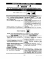
SAV_TIONS
I_
IMPROPER OPERATION OR MAINTENANCE
OF THIS PRODUCT COULD RESULT IN SERIOUS INJURY AND PROPERTY
DAMAGE. READ AND UNDERSTAND ALL WARNINGS AND OPERATING INSTRUCTIONS BEFORE USING THIS EQUIPMENT.
.so°x
oso
o [ li l
WHAT CAN HAPPEN
HOW TO PREVENT IT
GASOLINE AND GASOLINE VAPORS CAN BECOME IGNITED
BY COMING INTO CONTACT WITH HOT COMPONENTS SUCH
AS THE MUFFLER, FROM ENGINE EXHAUST GASES, OR
FROM AN ELECTRICAL SPARK.
TURN ENGINE OFF AND ALLOW IT TO COOL BEFORE
ADDING FUEL TO THE TANK. EQUIP AREA OF OPERATION
WITH A FIRE EXTINGUISHER
CERTIFIED TO HANDLE
GASOLINE OR FUEL FIRES,
COMBUSTIBLE MATERIALS WHICH COME INTO CONTACT
WITH HOT ENGINE PARTS CAN BECOME IGNITED,
ADD FUEL OUTDOORS IN A WELL VENTILATED AREA. MAKE
SURE THERE ARE NO SOURCES OF IGNIT[ON, SUCH AS
CIGARE-FrES NEAR REFUELING LOCATION.
OPERATE COMPRESSOR IN A CLEAN, DRY, WELL VENTILATED
AREA A MINIMUM OF FORTY-EIGHT INCHES FROM ANY BUILDING, OBJECT OR WALL. DO NOT OPERATE UNIT INDOORS
OR IN ANY CONFINED AREA.
STORE FUEL
COMPRESSOR.
UNATTENDED
OPERATION OF THIS PRODUCT COULD
RESULT IN PERSONAL iNJURY OR PROPERTY DAMAGE,
A
SECURE
LOCATION
ALWAYS REMAIN IN AI-FENDANCE
WHEN IT iS OPERA'RNG.
RISK OF BURSTING
IRTA_:
IN
WITH
AWAY
FROM
THE PRODUCT
I_
THE FOLLOWING CONDITIONS COULD LEAD TO A WEAKENING OF THE TANK, AND RESULT IN A
VIOLENT TANK EXPLOSION AND COULD CAUSE PROPERTY DAMAGE OR SERIOUS INJURY.
WHAT CAN HAPPEN
HOW TO PREVENT IT
1. FAILURE TO PROPERLY DRAIN CONDENSED WATER
FROM THE TANK, CAUSING RUST AND THINNING OF THE
STEEL TANK.
DRAIN TANK DAILY OR AFTER EACH USE, iF TANK DEVELOPS
A LEAK, REPLACE IT IMMEDIATELY WITH A NEW TANK OR
REPLACE THE ENTIRE COMPESSOR
2. MODIFICATIONS
NEVER DRILL INTO, WELD, OR MAKE ANY MODIFICATIONS TO
THE TANK OR ITS AT[AGHMENTS.
OR A_EMPTED
REPAIRSTO
THE TANK.
3. UNAUTHORIZED MODIFICATIONS TO THE UNLOADER
VALVE, SAFETY VALVE, OR ANY OTHER COMPONENTS
WHICH CONTROL TANK PRESSURE.
THE TANK IS DESIGNED TO WITHSTAND SPECIFIC OPERATING
PRESSURES.
NEVER MAKE ADJUSTMENTS
OR PARTS
SUBSTITUTIONS TO ALTER THE FACTORY SET OPERA_NG
PRESSURES.
4. EXCESSIVE VIBRATION CAN WEAKEN THE AIR TANK AND
CAUSE RUPTURE OR EXPLOSION. EXCESSIVE
VIBRATION WILL OCCUR IF THE COMPRESSOR IS NOT
PROPERLY MOUNTED OR IF THE ENGINE OPERATES
DO NOT REMOVE THE STIFFENER BAR CONNECTING THE
COMPRESSOR PUMP TO THE ENGINE, EXCEPT TO ADJUST BELT
TENSION, THEN SECURELY TIGHTEN THE STIFFNER BAR NUTS.
THIS BAR CONTROLS OUTFIT VIBRATION.
ABOVE RECOMMENDED
ATTACHMENTS
RPM.
& ACCESSORIES:
EXCEEDING
THE PRESSURE
RATING
OF AIR TOOLS, SPRAY
GUNS,
AIR OPERATED
ACCESSORIES,
TIRES
AND
OTHER
INFLATABLES
CAN
CAUSE
THEM
TO EXPLODE
OR FLY
APART, AND COULD
RESULT IN SERIOUS
INJURY.
FOR ESSENTIAL
CONTROL
OF AIR PRESSURE,
YOU MUST
INSTALL
A PRESSURE
REGULATOR
AND PRESSURE
GAUGE
TO THE AIR OUTLET
OF YOUR COMPRESSOR
FOLLOW
THE
EQUIPMENT
MANUFACTURERS
RECOMMENDATION
AND NEVER
EXCEED
THE MAXIMUM
ALLOWABLE
PRESSURE
RATING
OF
A_rACHMENTS.
NEVER
USE
COMPRESSOR
TO
INFLATE
SMALL
LOW-PRESSURE
OBJECTS
SUCH
AS CHILDREN'S
TOYS,
FOOTBALLS,
BASKETBALLS.
ETC.
3 - ENG
D20396 Rev 0
2/16/00
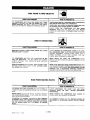
RISK
FROM
FLYING
OBJECTS
WHAT CAN HAPPEN
HOW TO PREVENT IT
THE COMPRESSED AIR STREAM CAN CAUSE SOFT TISSUE
DAMAGE TO EXPOSED SKIN AND CAN PROPEL DIRT, CHIPS,
LOOSE PARTICLES AND SMALL OBJECTS AT HIGH SPEED,
RESULTING IN PROPERTY DAMAGE OR PERSONAL INJURY.
ALWAYS WEAR ANSI Z87.1 APPROVED SAFETY GLASSES WITH
SIDE SHIELDS WHEN USING THE COMPRESSOR.
NEVER POINT ANY NOZZLE OR SPRAYER TOWARD ANY PART
OF THE BODY OR AT OTHER PEOPLE OR ANIMALS.
ALWAYS TURN
THE COMPRESSOR
OFF AND
BLEED
PRESSURE
FROM THE AIR HOSE AND TANK BEFORE
ATTEMPTING MAINTENANCE, ATTACHING TOOLS OR ACCESSORIES.
RISK
WHAT
CAN
BREATHING EXHAUST FUMES
SERIOUS INJURY OR DEATH.
TO BREATHING
HAPPEN
FROM
HOW TO PREVENT IT
WILL CAUSE
ALWAYS OPERATE AIR COMPRESSOR OUTSIDE IN A CLEAN,
WELL VENTILATED AREA. AVOID ENCLOSED AREAS SUCH AS
GARAGES, BASEMENTS, STORAGE SHEDS, WHICH LACK A
STEADY EXCHANGE OF AIR. KEEP CHILDREN, PETS AND
OTHERS AWAY FROM AREA OF OPERATION.
THE COMPRESSED AIR FROM YOUR COMPRESSOR IS NOT
SAFE FOR BREATHING!
THE AIR STREAM MAY CONTAIN
CARBON MONOXIDE, TOXIC VAPORS OR SOLID PARTICLES
FROM THE TANK.
NEVER INHALE AIR FROM THE COMPRESSOR
EITHER
DIRECTLY OR FROM A BREATHING DEVICE CONNECTED TO THE
COMPRESSOR.
SPRAYED MATERIALS SUCH AS PAINT, PAINT SOLVENTS, PAINT
REMOVER, INSECTICIDES, WEED KILLERS, CONTAIN HARMFUL VAPORS AND POISONS.
WORK IN AN AREA WITH GOOD CROSS-VENTILATION. READ
AND FOLLOW THE SAFETY INSTRUCTIONS PROVIDED ON THE
LABEL OR SAFETY DATA SHEETS FOR THE MATERIAL YOU ARE
SPRAYING. USE A NIOSH/MSHA APPROVED RESPIRATOR
DESIGNED FOR USE WITH YOUR SPECIFIC APPLICATION.
RISK
ENGINE
FROM
MOVING
PARTS
WHAT CAN HAPPEN
HOW TO PREVENT IT
THE ENGINE CAN START ACCIDENTALLYIF
THE FLYWHEELIS
TURNED BY HAND OR MOVED BY PULLING ON THE STARTER
ROPE.
ALWAYS DISCONNECT
THE SPARK PLUG
PRESSURE
FROM
THE TANK
BEFORE
MAINTENANCE.
AND
BLEED
PERFORMING
MOVING
PARTS SUCH AS THE
CAN CAUSE
SERIOUS
INJURY,
WITH YOU OR YOUR CLOTHING
NEVER OPERATE THE COMPRESSOR
WITH
COVERS WHICH ARE DAMAGED OR REMOVED
GUARDS
PULLEY,
IF THEY
FLYWHEEL
AND BELT
COME INTO CONTACT
ATTEMPTING
TO OPERATE
COMPRESSOR
WITH
DAMAGED
OR MISSING
PARTS
OR ATTEMPTING
TO REPAIR
COMPRESSOR WITH
PROTECTIVE
SHROUDS
REMOVED
CAN EXPOSE
YOU TO
MOVING
PARTS
AND
CAN
RESULT
IN SERIOUS
INJURY.
4-ENG
D203_
Rev
0
2/16/0Q
ANY REPAIRS
PERFORMED
NEL.
REQUIRED
ON
BY AUTHORIZED
OR
THIS PRODUCT
SHOULD
BE
SERVICE
CENTER
PERSON-
RISK OF BURNS
WHAT CAN HAPPEN
HOW TO PREVENT
IT
TOUCHING
EXPOSED METAL SUCH AS THE COMPRESSOR
HEAD OR OUTLET TUBES OR CONTACT WITH HOT ENGINE
PARTS, SUCH AS THE MUFFLER, CAN RESULT IN SERIOUS
BURNS.
NEVER TOUCH ANY EXPOSED METAL PARTS ON ENGINE OR
COMPRESSOR DURING OR IMMEDIATELY AFTER OPERATION.
ENGINE AND COMPRESSOR WILL REMAIN HOT FOR SEVERAL
MINUTES AFTER OPERATION.
THE GASOLINE ENGINE, THE ENGINE MUFFLER, THE COMPRESSOR HEAD AND TUBING BECOME VERY HOT DURING
OPERATION.
DO NOT REACH AROUND PROTECTIVE SHROUDS OR ATTEMPT
MAINTENANCE UNTIL UNIT HAS BEEN ALLOWED TO COOL.
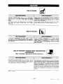
RISK
OF FALLING
WHAT CAN HAPPEN
HOW TO PREVENT IT
A PORTABLE COMPRESSOR
CAN FALL FROM A TABLE,
WORKBENCH OR ROOF CAUSING DAMAGE TO THE COMPRESSOR AND COULD RESULT IN SERIOUS INJURY OR DEATH TO
THE OPERATOR.
ALWAYS OPERATE COMPRESSOR
IN A STABLE SECURE
POSITION TO PREVENT ACCIDENTAL MOVEMENT OF THE UNIT.
NEVER OPERATE COMPRESSOR ON A ROOF OR OTHER
ELEVATED POSITION. USE ADDITIONAL AIR HOSE TO REACH
HIGH LOCATIONS.
RISK
OF PROPERTY
(Fire,
DAMAGE
WHEN
COMPRESSOR
Inhalation,
Damage
TRANSPORTING
to Vehicle
WHAT CAN HAPPEN
GSW.99
--
n
Surfaces)
HOWTO
FUEL OR OIL CAN LEAK OR SPILL AND COULD RESULT IN FIRE
OR BREATHING HAZARD, SERIOUS INJURY OR DEATH CAN RESULT. FUEL OR OIL LEAKS WILL DAMAGE CARPET, PAINT OR
OTHER SURFACES IN VEHICLES OR TRAILERS.
I
PREVENT
IT
IF COMPRESSOR IS EQUIPPED WITH A FUEL SHUT-OFF VALVE,
TURN THE VALVE TO THE OFF POSITION BEFORE TRANSPORTING TO AVOID FUEL LEAKS. IF COMPRESSOR IS NOT EQUIPPED
WITH A FUEL SHUT-OFF VALVE, DRAIN THE FUEL FROM TANK
BEFORE TRANSPORTING. TRANSPORT FUEL ONLY IN AN OSHA
APPROVED CONTAINER. ALWAYS PLACE COMPRESSOR ON A
PROTECTIVE MAT WHEN TRANSPORTING TO PROTECT AGAINST
DAMAGE TO VEHICLE FROM LEAKS. REMOVE COMPRESSOR
FROM VEHICLE IMMEDIATELY UPON ARRIVAL AT YOUR DESTINATION.
9122199
5 - ENG
D20396
F!ev
0
2/16/00
Model No.
Engine Horsepower
Compressor DisplacementCFM
CompressorBore
Compressor Stroke
Air Tank/Capacity- Gallons
Approximate UnloaderReset Pressure
Approximate UnloaderBlow-OffPressure
SCFM @ 40 psig
SCFM @ 90 psig
SCFM: Standard cubic feet per minute; a unit of
measure of air delivery.
ASME: American Society of Mechanical Engineers;
made, tested, inspected and registered to meet the
standards of the ASME.
Unloader Reset Pressure: When the tank pressure
drops to a predetermined point, the unloader valve
closes. The tank pressure will now increase until it
reaches the unloader blow-off pressure.
Cubic feet per minute.
The following
accessories
• SPRAY GUNS
• BLOW GUNS
• AIR CAULKING GUNS
eAIR POWER WASHER
"SANDBLASTERS
• AIR BRUSH SET
oIN-LINE FILTERS
• TIRE CHUCKS
are available
through the current general sales catalog or at full-line Sears stores,
• PAINT TANKS
•AIR TOOLS:
•AIR CARRY TANKS
Sanders
• INFLATOR KITS
Drills
• QUICK CONNECTOR SETS
Impact Wrenches
(various sizes)
Rachets
• AIR PRESSURE REGULATORS
=AIR HOSE:
• OIL FOG LUBRICATORS
1/4" or 3/8" I.D.
in various
6 - ENG
020396
Rev
0
2/16/00
2"
20ASME
90
110
12.0
10.0
Unloader Blow-Off Pressure: All models are continuously running outfits controlled by tank pressure when
the maximum tank pressure is obtained, the unloader
valve will blow-off. This will cause the compressor to
exhaust the air to the atmosphere and not the tank.
This decreases the load on the engine and allows it to
run at a near no-load condition.
PSIG: Pounds per square inch gauge; a unitof
measure of pressure.
CFM:
919.157251
5
15.3
2 7/8"
lengths
You have purchased an air compressor unit consisting of
a 2 cylinder, single-stage air compressor
pump and air
tank. Included with portable compressors
are wheels,
gauges, and handle.
An air pressure regulator is usually required for most of
these applications.
Regulators can be purchased from
most Sears stores or through the Sears Power Tool
Catalog.
Your air compressor can be used for operating paint spray
guns, air tools, caulking guns, grease guns, air brushes,
sandblaster, or inflating tires and plastic toys, spraying
weed killers, insecticides,
etc.
Separate air transformers which combine the functions or
air regulation and/or moisture and dirt removal should be
used where applicable.
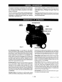
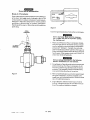
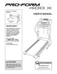
UNLOADER VALVE
ON/OFF
SWITCH-_-_
VALVE
SHUTOFF VALVE
CHECK
VALVE
Figure
1
Air Compressor
Pump: To compress air, the pistons
move up and down in the cylinders. On the downstroke,
air is drawn in through the air intake filter and then through
the air intake valves. The exhaust valve remains closed.
On the upstroke of the piston, air is compressed.
The
intake valves close and compressed
air is forced out
through the exhaust valve, th rough the outlet tube, through
the check valve and into the air tank. Working air is not
available until the compressor has raised airtank pressure
above that required at the air outlet.
Throttle Control: Athrottle control has been incorporated
as an extra feature. When maximum tank pressure is
reached and the unloader valve unloads air, it also
activates a throttle control on the engine. This gas saving
featu re holds the engine at a factory-set idling speed until
air pressure in the air tank drops to reset pressure; it then
reactivates the throttle control and accelerates the engine
to full throttle.
Unloader Valve: All models are continuously
running
outfits controlled by tank pressure. When the maximum
tank pressure is obtained, the unloader valve will exhaust
the compressed air to the atmosphere (blow-off). When
the pressure drops to a predetermined point, the unloader
valve closes and causes the tank pressure to increase.
Safety Valve: If the pressure switch does not shut off the
air compressor at or near its cut-out pressure setting, the
safety valve will protect against high pressure by "popping out" at its factory set pressure (slightly higherthan the
pressure switch cut-out setting).
Check Valve: When the air compressor is operating, the
check valve is "open," allowing compressed air to enter
the air tank. When the air compressor
reaches "cut-out"
pressure, the check valve "closes," allowing air pressure
to remain inside the air tank. If the air is not unloaded, the
motor will try to start, but will be unable to. The check valve
allows the motor to restart freely.
Shut Off Valve: Turn the knob counterclockwise
the valve and clockwise to close.
to open
7 - ENG
D20396
Rev
0
2/16/00
Item You Will Need To Assemble Your Compressor
• 20 oz. of oil for the engine (see Briggs & Stratton
instructions).
Use 10W30 high quality motor oil
• 16 oz. of Sears compressor oil or SAE 20-20W
• teflon tape
• a9/16" socket oropen-endwrench
ferattachingthe
wheels
• a 7/16" open-end wrench for attaching the foot
extension bracket and rubber feet
• a W' open-end wrench for attaching the shut-off
valve and air outlet adapater.
Installing Handle, Foot
Wheels, Outlet Valve
Extension
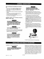
I_,V;l_,1:]Oll_[€
EXCESSIVE TANK VIBRATION CAN
WEAKEN THE AIR TANK AND CAUSE
RUPTURE OR EXPLOSION. RUBBER FEET
MUST BE INSTALLED.
2,
the air tank bracket. Use one cap screw, one lock
washer, and one hex nut at each end. Tighten.
3.
Bracket,
THE WHEELS AND HANDLE DO NOT
PROVIED ADEQUATE CLEARANCE, STABILITY OR SUPPORT FOR PULLING THE UNIT
UP AND DOWN STAIRS OR STEPS. THE
UNIT MUST BE LIFTED OR PUSHED UP A
RAMP.
Oo not use the
port
for lifting
engine
gas tank
Attach the rubber feet to the bottom of the foot
extension bracket, Attach foot extension bracket to
The leg bracket on the underside of the air
compressor tank has 2 holes on each side for
mounting the wheels. Place one shoulder bolt through
the hole in a wheel. Next, push the bolt through the
LOWER hole ofthe leg bracket and screw on one
hexlocking nut. The special locking nut does not turn
freely. Tighten the nut firmly until it contacts the tan k
leg. See pg. 16. The outfit will sit level if the wheels
are properly installed.
4. Apply teflon tape to the tapered pipe threads on
the adapter and tighten into the manifold. Install the
swivel connection end of the shut-off valve to the
straight threaded end of the adapter (pipe sealant is
not required) and tighten this connection. See photo
below.
as a sup-
the air compressor.
1. Insert the handle into pockets under the tank saddle.
Put one set screw through hole in one side of tank
saddle and tighten down on handle.
It may be necessary
to brace or support
one end of the outfit when attaching
the
wheels
and the foot extension
bracket
because
the air compressor
will have a
tendency
to tip before
both wheels are
assembled.
SHUT-OFF
VALVE
SWFVEL
MANIFOLD
CONNECTION
5. Attach the spark plug wire to the spark plug.
Location
Operate the air compressor
in a clean, dry and well
ventilated area. The air intake filter must be kept clear
of obstructions which could reduce air delivery of the air
compressor. The air compressor should be located at
least 12" away from walls or other obstructions
that
could interfere with the flow of air through thefan bladed
flywheel. The air compressor
crankcase and head are
designed with fins to provide proper cooling, if humidity
is high, Sears air filter can be installed to remove
excessive moisture. Closely follow the instructions pack aged with the filter for proper installation.
of the Air Compressor
.I_l¥1_I_ U_f_:
EXCESSIVE
TANK VIBRATION
CAN WEAKEN
THE AIR TANK AND CAUSE RUPTURE
OR
EXPLOSION.
RUBBER FEET MUST BE
INSTALLED.
8-ENG
D20396
Rev
0
2116/00
Permanent
Installation
BOLTING LEGS TO A STIFF SURFACE CAN
CAUSE TANK RUPTURE RESULTING IN
SERIOUS INJURY OR DAMAGE. DO NOT
PERMANENTLY MOUNT COMPRESSOR TO
ANY SURFACE WITHOUT USING THE
VIBRATION MOUNT KIT.
This compressor
may be permanently mounted in a
Ioaction such as e truck bed, it desired. A vibration
mount kit is included for this purpose.
1. In order to maintain adequate ventilation for compressor cooling and to avoid contact with pick-up
truck bed, always mount the outfit at least 8" from
any vertical wall. Using the holes in the air tank legs
as a guide, mark and drill four 5/16" diameter holes
in the mounting surface.
2. Insert the vibration mounts in the mounting holes.
Place a flat washer under the mounting surface and
secure each mount with a lock washer and nut. See
figure 2.
3. Set the outfit on the exposed threaded ends of the
mount to the air tank legs with a lock washer and nut.
Lubrication,
Compressors
Oil and Gasoline
are shipped
without
oil. Do not
attempt to operate this air compressor
without
first adding oil to the compressor
pump
crankcase
and engine crankcase.
Place unit on a level surface. Remove compressor oil fill
plug and slowly add a special compressor oil such as
Sears compressor oil or SAE-20-20W SF motor oil until
it is even with the top of the oil fill hole. (It must not be
allowed to be lower than 3/8" - 6 th reads down - fro m the
top.) When filling the crankcase,
the oil flows very
slowly. If the oil is added too quickly, it will overflow and
appear to be full. (Crankcase oil capacity is 16 fluid
ounces.) Under winter-type conditions use SAE 10W oil.
(Multi-viscosity
oil - 10W30 - will leave carbon deposits
on critical components reducing performance and compressor life.) Replace oil fill plug.
Remove engine oil fill plug and slowly add oil to the point
of overflowing.
Use a high quality oil classified "FOR
SERVICE SC, SD, SE or MS,". See Briggs and Stratton
"OPERATING AND MAINTENANCE INSTRUCTIONS" for
recommended SAE viscosity grades. (Engine crankcase
capacity is 20 fluid ounces.)
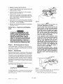
For your convenience, purchase a W' NPT nipple 2V2"
long, and a 1/4" NPT x 1/4" NPT coupling (pipe collar) to
allow ease in draining oil. Remove oil drain plug on the
gas tank side of the engine and install the nipple. Thread
the ooupting on the end of the nipple and screw the drain
plug in the coupling. See figure 3.
LOCKWASHER
COUPLING
DRAIN
NIPPLE
Figure 3
With the unit in a level position, fill the gas tank (approx.
3/4 gal.) with fresh, clean unleaded gasoline. Regular
gas is an acceptable substitute. Do not use premium
gasoline.
Figure 2
Gasoline
Vapor is highly flammable.
Refuel
outdoors
preferably,
or only in well ventilated areas.
Do not refuel or check gasoline level while the engine is running.
Do
not store, spill or use gasoline
near an
open flame.
9 - ENG
D20396
Ray
0
2/16/0Q
Oo not mix oil with gasoUne.
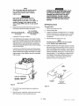
Break-In
Procedures
[ IRUN
Open outlet valve to prevent pressure from building up
in the tank. Set toggle lever of unloader valve in the
vertical position to relieve compressor
head pressure.
See figure 4. Move the choke lever to "choke" position
and move on -off lever to the "on" position. See figure 5.
Pull choke allthe way out. Move stop switch away from
spark plug.
OPEN
POSITION
Figure 5
A warm engine requires less choking than a cold engine.
Unit
is top
sor is stable
the starting
heavy.
Make
and will
cord,
sure
the compres-
not tip before
pulling
I
tt'tP__ ".
k&
I
1.
/
CLOSED
POSITION
Place your left hand on the air compressor handle,
and your right hand on the starter handle, and pull
cord out quickly to overcome engine compression
and prevent "kickback". If engin e does not start,
push the choke about three-quarters of the way in or
choke level three quarters to the left and pull starter
handle again. When engine starts, push choke in or
choke lever to the left gradually.
RE_r..IlII
| [e]_
Serious damage may result in the following
break-in instructions are not followed.
Figure 4
2,
Pump Break-in: Open the outlet valve to prevent tank
pressure build-up. Run the air compressor for 30
minutes to seat the rings and lubricate all internal
surfaces. This operation must be completed only
once when first putting the unit in service.
3.
After completing the above, and when ready to begin
using the compressor, move the unloader valve
toggle lever to a horizontal position. Close the outlet
valve to build tank pressure.
4,
Engine Break-in: After the first 5 hours of normal
running, change the engine oil. Then after every 25
hours the engine oil should be changed.
10 - ENG
D20396
Rev
0
2/16/00
1. Before attaching an air hose or accessory, make
sure the engine is off. Close the outlet valve or
pressure regulator. (If an optional air pressure
regulator is not used, do not use accessories rated
at less than 110 psig.)
2. Attach
hose and accessory.
TOO MUCH AIR PRESSURE CAUSES A
HAZARDOUS RISK OF BURSTING. CAREFULLY FOLLOW STEPS 3 THROUGH 10
EACH TIME THE COMPRESSOR IS USED.
3. Check the manufacturer's
maximum pressure
rating for air tools and accessories. The compressor
outlet pressure must never exceed the maximum
pressure rating.
4. Start the engine and allow tank pressure to build.
Your outfit is ready for use.
Compressed
air from the outfit may contain
water
condensation
and oil mist. Do not
spray unfiltered
air at an item that could
be damaged.
Some air operated
tools or
devices may require filtered
air. Read the
instructions
for the air tool or device.
When you are finished:
5. Turn offengine.
6. Shut-off outlet valve or air pressure regulator.
7. Remove air tool or accessory.
8. Open outlet valve or regulator and allow air to slowly
bleed from the tank. Close the outlet vavle or regulator
when the tank pressure is approximately 20 psig.
WATER WILL CONDENSE IN TANK. IF NOT
DRAINED, WATER WILL CORRODE AND
WEAKEN THE AIR TANK CAUSING A RISK
OF TANK RUPTURE. SEE STEP 9.
g.
With tank pressure at approximately 20 PSI, open
the drain cock and allow moisture to drain. Turn the
drain T-handle counterclockwise
to open.
NOTE
If drain cock is clogged, release all air pressure. The drain cock can then be removed,
cleaned, and then reinstalled.
10, After the water has been drained, close the drain
cock. The compressor outfit can now be stored.
DURING MAINTENANCE, YOU COULD BE EXPOSED TO COMPRESSED AIR OR MOVING PARTS. PERSONAL INJURIES CAN OCCUR. BEFORE DOING ANY MAINTENANCE OR REPAIR, DISCONNECT THE
SPARK PLUG WIRE TO PREVENT ACCIDENTAL STARTING, AND RELIEVE AIR TANK PRESSURE. NEVER
OPERATE THE COMPRESSOR WITH THE BELT GUARD REMOVED.
Air Compressor
Compressor
A clean air compressor and engine run cooler and
provide longer service. Clean or blow off fins and any
other parts of the air compressor and enginethat collect
dust or dirt, Do not place rags, containers
or other
material on or against the compressor.
Ventilation is
necessary to maintain proper air compressor operating
temperature.
Check oil level in the crankcase daily. The oil level
should be even with the top of the fill hole and must not
be allowed to be lower than 3/8" from the top (6 threads)
at any time. It is recommended
that the oil be changed
after every 100 hours of operation. To drain the oil,
remove the oil drain plug and collect the oil in a suitable
container. Be sure to replace the plug securely before
adding new oil. Use a special compressor
oil such as
Sears compressor
oil or SAE 20-20W SF motor oil.
(Crankcase
oil capacity is 16 fluid ounces.) Under
extreme winter conditions
use 10 weight oil. Multiviscosity oil (10W30) will leave carbon deposits
on
critical components
reducing performance
and compressor life.
Compressor
Pump Air Intake Filter -Inspection and Replacement
A dirty air filter will not allow the compressor to operate
at full capacity. Before you use the compressor, check
the air filter to be sure it is clean.
If it is dirty, replace with a new filter. The filter may be
removed by using a pair of needle nose pliers or a
screwdriver. Pull or pry out the old filter and push in a
new one.
Check
Oil -- Checking
Valve -- Inspection
and Changing
and Replacement
Remove the check valve for inspection or replacement
if air is leaking constantly back through the check valve.
Use the following procedure to inspect, clean or replace
the check valve.
11 - ENG
020396
Rev
0
2/16/00
1.
Release air pressure from the air tank.
2. Loosen the top and bottom tube nuts and remove the
outlet tube (Nos. 4 and 6).
3. Unscrew the check valve (turn counterclockwise)
using a socket wrench (No. 3).
4. Check that the valve disc moves freely inside the
check valve and that the spring holds the disc in the
upper, closed position. The check valve may be
cleaned with a solvent.
5,
NEEDLEVALVE
Apply sealant to the check valve threads. Reinstall
the check valve (turn clockwise). The disc should still
move freely -- do not overtighten.
Figure 6
NOTE
6.
Replace the outlet tube and tighten top and bottom
nuts (Nos. 6 and 4).
Safety Valve
ment
-- Inspection
The air cleaner
must be in place when
carburetor
adjustments
are made.
Turn the needle valve clockwise
(in) until the
engine
misses,
noting
the
valve position
(lean mixture).
Turn the needle valve counterclockwise
(out) until engine runs roughly,
and Replace-
again
noting
valve position
(rich mixture).
Now, turn the needle
valve clockwise
(in) to
the point
midway
between
lean and rich
IF THE SAFETY VALVE DOES NOT WORK
PROPERLY OVER-PRESSURIZATION
MAY
OCCUR, CAUSING AIR TANK RUPTURE OR
EXPLOSION. OCCASIONALLY PULL THE
RING ON THE SAFETY VALVE TO MAKE
SURE THAT THE SAFETY VALVE OPERATES
FREELY. IF THE VALVE IS STUCK OR DOES
NOT OPERATE SMOOTHLY, IT MUST BE
REPLACED WITH THE SAME TYPE OF VALVE
HAVING AN IDENTICAL PRESSURE RATING.
Engine
-- Oil Change
where
and Air Cleaner
If the throttle
mechanism
fails to operate
smoothly,
preventing the engine from returing
to full throttle
speed
when
tank pressure
falls below 90 psig, it may be necessary
to
lubricate
it with a light lubricating
oil. See
Read the Briggs & Stratton "Operating and Maintenance
Instructions" that were provided with your compressor.
figure
The gasoline engine was adjusted and set at the factory
to ensure correct operation. However, variationsin gasoline quality and octane, humidity, altitude or load may
adversely affect engine performance. As a result, minor
adjustments of fuel mixture or speed controls may be
necessary.
may be damaged
if
Turn the needle valve 1_/2revolutions counterclockwise
to establish a point of reference. Start the engine and
allow it to warm up.
rER
SLOWER
Figure 7
Proper no-load engine speed may be checked
adjusted using the following procedures:
1.
12 - ENG
Hey
0
2/16/00
7.
LUBRICATE
To adjust the fuel mixture, turn the needle valve clockwise until it closes• See figure 6.
D20396
runs smoothly.
slightly higher level by loosening
the two jam
nuts on the throttle
control cylinder,
readjusting
its position
and retightening
the
nuts.
See figure
7. Proper
idle speed
is
between
2400 and 2600 RPM.
-- Adjustments
The needle valve point
turned in too far.
the engine
If the compressor
stalls frequently
during
acceleration
from idle speed, richen mixture
sightly
(by turning
the needle
valve out
slowly).
If this adjustment
does not eliminate the stalls, adjust the idle speed
to a
See Briggs & Stratton "Operating and Maintenance Instructions" for information regarding engine oil changes
and air cleaner service.
Engine
any
Remove the belt guard and belt. Start engine
and
NOTE
"vvRIiW_]_IR[_
This is the only time you should operate
your compressor
with the belt guard
removed.
Use caution when checking
engine
speed.
High engine speeds greatly
vibration
loads on air tank.
increase
This could
weaken
the tank and cause it to rupture
or
explode.
Damage
to the engine can also
occur. Engine
RPM must be set per specification.
2.
SERIOUS INJURY OR DAMAGE MAY OCCUR
IF PARTS OF THE BODY OR LOOSE ITEMS
GET CAUGHT IN MOVING PARTS. NEVER
OPERATE THE OUTFIT WITH THE BELT
GUARD REMOVED. THE BELT GUARD
SHOULD BE REMOVED ONLY AFTER THE
SPARK PLUG WIRE HAS BEEN DISCONNECTED.
Measure engine speed with belt removed using a
tachometer. Speed should be as follows:
Compressor Model No.
No-Load (Max)
Speed (± 100 RPM)
919.157251
Belt Replacement
To replace belt:
1.
Disconnect
2.
Remove belt guard.
3.
Loosen four engine mounting screws, two saddle/
stiffener plate screws, handle set screw, and stiff
ener bar nut on engine and slide engine toward
compressor.
4.
Remove belt and replace with new.
3700 RPM
If speed is correct go to Step 5.
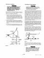
3.
Four bolts fasten the engine to tank base. Position
yourself on the starter rope side of engine and locate
that engine mounting bolt nearest you on the left. In
this area, there is one vertical spring. Locate the
vertical spring situated directly above the mounting
bolt just described.
Locate
spring
pliers,
engine
engine
spark plug wire.
NOTE
The belt must be centered
over the grooves
on the flywheel
and engine pulley.
5.
lever to which the lower end of the vertical
is attached. See figu re 8. Using needle nosed
bend the lever slightly downward to increase
speed or bend slightly upward to decrease
speed.
Push the engine back into regular position. Achieve
belt tension by inserting a large screwdriver into the
hole in the saddle which is located on the belt guard
side of the saddle below the engine and prying the
stiffener plate back. See figure 9. Proper tension is
approximately
1/4" belt deflection measured mid
way between the pulley and flywheel when a 3pound weight or equivalent finger pressure is
applied at this point. See figure 10.
TANK
SADDLE
ACCESS
THROTTLE
ADJUSTMENT
INCREASE-BEND
DOWN
DECREASE o BEND UP
/
STIFFENER
PLATE
BEND HERE
ADJUSTMENT
SLOTS IN
STIFFENER PLATE
Figure 8
Figure 9
:4.
Check the engine speed again and readjust as
necessary.
5.
Shut off engine, install belt, adjust belt tension (see
Belt Replacement) and reinstall belt guard.
13 - ENG
D20396
Rev
0
2/16/00
NOTE
Once the engine
its factory
set
pulley
location,
has been moved
the
grooves
flywheel
and pulley must be aligned
1/16" to prevent
belt wear,
Pulley
Figure
Hold belt tension until two engine mounting
are tightened securely+
7.
Tighten remaining engine mounting screws, saddle/
stiffener plate screws, handle set screw and
stiffener bar nut.
8.
Reinstall belt guard and screws.
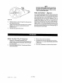
Before
screws
You Store The Air Compressor
3.
Review the "Operating Procedures +'and
"Maintenance" sections on the precedingpagesand
perform maintenance as necessary. Drain the water
from the air tank.
2.
Reviewthe Briggs&Stratton "Operating and Maintenance Instructions".
Rev
0
2/16/00
-- Alignment
pulley grooves. Squareness is achieved when the pulley
grooves are an equal distance from the straightedge on
both sides of the motor shaft.
1.
D20396
Flywheel
within
The compressor flywheel and motor pulley must be inline
(in the same plane) within 1/16" to assure belt retention
within sheave grooves. To check align ment, disconnect
spark plug wire and remove the beltguard. Place a
straightedge against the outside of the flywheel and
measure the distance from it to the nearest groove.
Alignment isachieved when the other end of the straightedge is within f/16" of the measured dimension at the
10
6.
and
from
of the
Remove the air tool or accessory.
4.
Protect the air hose from damage (such as being
stepped on or run over). Wind it loosely around the
outfit handle.
5,
Store the compressor
14 - ENG
in a clean and dry location,
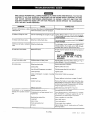
gVtIW-'1_
UNIT CYCLES AUTOMATICALLY WHEN POWER IS ON. WHEN DOING MAINTENANCE, YOU MAY BE
EXPOSED TO VOLTAGE SOURCES, COMPRESSED AIR OR MOVING PARTS. PERSONAL INJURIES
CAN OCCUR. BEFORE PERFORMING MAINTENANCE OR REPAIR, TURN OFF AND LOCK OUT
ELECTRIC POWER AND BLEED OFF AIR TANK PRESSURE. NEVER OPERATE THE COMPRESSOR
WITH THE BELT GUARD REMOVED.
PROBLEM
CAUSE
Excessive tank pressure - safety
valve pops off.
Unloader valve does not release pressure
when tank reaches "blow-off"
pressure•
Unloader
Air leaks at fittings
Tube or hose fittings are not tight enough.
Tighten fittings where air can be heard escaping.
Check fittings under soapy water solution. DO NOT
OVER-TIGHTEN.
Air leaks inside check valve,
Defective
or dirty check valve.
Remove and clean or replace check valve. DO NOT
OVER-TIGHTEN.
Continuous
valve•
Defective
checkvalve,
Turn off engine, move unloader valve toggle lever to
vertical position. If air leaks out of tank through
or hose.
air leak at unloader
CORRECTION
unloader
Air leaks at air tank welds.
Defective
air tank.
valve must be replaced•
valve, clean or replace check valve.
Air tank must be replaced.
any leaks.
DO NOT DRILL
WISE MODIFY
WEAKENED.
Air leak from safety valve.
Possible
defect
Knocking
Defective
check valve.
noise,
in safety valve•
or engine).
Loose flywheel.
pulley set screw.
Maintain
Tighten
or engine
mountin(
Check
prescribed
oil level• Add oil
screw•
bolts. Tighten
as required•
Loose belt.
Tension
Carbon build-up.
Remove the head and valve plate. Clean the valve
)late and the top of the piston. (Be sure carbon does
not fall into the cylinder.) Reassemble to 25-30 ft,lbs.
belt per instructions
using new gasket
Compressor
is not supplying
enough air to operate accessories.
INTO, WELD OR OTHERAIR TANK. IT WILL BE
Remove and clean or replace.
Loose pulley.
Loose compressor
screws.
repair of
Operate safety valve manually by pulling on ring. If
valve still leaks, it should be replaced.
Tighten
Low oil level (Compressor
Do not attempt
Stiffener
bar loose,
Prolong
excessive
Compressor
requirement.
Restricted
Check
use of air.
is not large enough
Decrease
for air
air intake filter.
and torque
both nuts and tighten
amount
on page 12, step 5.
screws.
if required
of air usage.
Check the accessory air requirement• If it is higher
than the SCFM or pressure supplied by your air
compressor, you need a larger compressor.
Clean or replace
air intake filter•
Loose belt.
Adjust
Hole in hose.
Check and replace•
belt tension.
Check valve restricted
Remove and clean or replace•
Air leaks•
Tighten fittings• (See Air Leaks section
shooting Guide•)
of Trouble-
15 - ENG
D20396
Rev
0
2/16/00
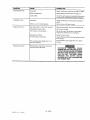
PROBLEM
CAUSE
Excessive belt wear.
Loose belt.
CORRECTION
Adjust
tension
per instruction
Pulley misalignment.
Adjust
pulleys
per instructions
Loose pulley.
Check for worn keyway or pulley bore. Also check
for bent motor
Squealing
sound.
Loose belt.
Adjust belt tension
step 5.
There is no oil in the compressor.
Engine
will not run
The stop switch
The gasoline
The choke
Excessive
vibration.
shaft. Replace
is in the "stop"
on page 12, step 5.
on page 13.
parts if necessary.
per instructions
on page 12,
Add oil to top of fill hole in base.
position.
tank is empty.
Move the stop switch
away from the spark plug.
Fill the tank with gas.
is not set properly.
Re-set the choke. Remember, a warm engine
requires less choking that a cold engine.
Improper fuel mixture,
Air tank pressure is too high,
Adjust
The unloading valve toggle lever is in a
horizontal
position.
Place unloading
3osition.
Stiffener bar or engine and compressor
mounting screws are loose.
the fuel mixture,
Open the ball valve and reduce tank pressure to less
than 40 psig.
valve toggle lever in a vertical
EXCESSIVE
VIBRATION
COULD
WEAKEN THE AIR TANK AND CAUSE IT
TO RUPTURE OR EXPLODE. STIFFENER
BAR NUTS AND MOUNTING
SCREWS
MUST BE KEPT TIGHTENED.
NEVER
OPERATE
THE
OUTFIT
UNLESS
EQUIPPED
WITH THE STIFFENER
BAR
AND RUBBER FEET.
16 - ENG
D20396
Rev
0
2/16/00
17 - ENG
D20306
Rev
0
2/16/00
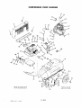
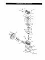
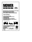
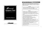
COMPRESSOR
PUMP
DIAGRAM
13
/
1
11..._._:_
4
<:'--_jlb
IO
1
•20
5B
56
47
43"
41
41
18 - ENG
D20396
Rev. 0
2/16/00
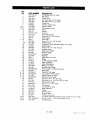
KEY
NO.
1
2
3
4
5
6
7
,,'J 8
,z,/9
10
11
12
13
14
15
J
16
17
17A
18
19
2O
21
22
23
24
25
26
27
28
29
3O
31
32
33
34
X 35
X 36
X 37
X 38
39
4O
41
42
43
44
45
46
47
49
5O
j',/51
•/./52
,/,/53
pART NUMBER
SSF-953-ZN
CAC-87-1
CAC-437-2
S$P-7812
SSP-7811
AC-0675
AC-0676
SSP-6422
CAC-1041
SSP-6423
CAC-2-1
SSF-8113-ZN
LA-1779-1
SSF-935
255-18
265-17
SSF-g55
CAC-293-1
AC-0337
LA-3020
SSF-928
0AC-423
TIA-4150
GA-348
SS-3222-CD
CAC-226
SSV-4
SS-2110
TA-4473
1,6,-3069
LA-2373-1
CAC°4293
CAC-60
SSF-8080-ZN
SS-2707
SS-656-CD
SS-1503°CD
CAC- 165
SS-6506-CD
$S-391
SS-2-ZN
SST°5301
SS-655-ZN
DAC-159
21181-506
LA-3028-1
SUDL-43-1
CAC-42°1
SSF-30T7
AC-0677
CAC-4275
NOT AVAILABLE
CAC-!036
Self-tapping screw (7 used)
Belt guard
Check valve
Nut sleeve assy 1/2" (2 used)
Nut sleeve assy 1/4" (4 used)
Outlet tube
Pressure release tube
Elbow (3 used)
Compression Spring
Elbow
Bracket
Lock nut
Label, Hot Surface
Screw, #8-32 x 3/8" (2 used)
Filter retainer
Intake filter
Screw, 3/8 - 18 x 7/8" (4 used)
Cylinder head
Compressor pump assembly Model 919.157250
Warning label
Screw, 5/16 - 18 x 7/6" (6 used)
Unloader valve
Safety valve ASME
Pressure gauge
Pipe plug
Manifold
Globe Valve, 1/4" NP]"
Nipple
Air tank, 20 gallon ASME
Label, Craftsman
Label, Maintenance
Wheel, 8" (2 used)
Shoulder bolt (2 used)
Hex nut, #3/8"-16 UNC-2B (2 used)
Drain Valve
Nut #5/16-18 (8 used)
Lock washer, #5/16 (8 used)
Vibration mount (4 used)
Washer, #5/16 (4 used)
Set screw, #1/4 - 20 x 5/8" long
Cap screw, #1/4 - 20 x 3/4" long (4 used)
Rubber feet (2 used)
Hex nut, 1/4" - 20 (4 used)
Foot bracket
Lock washer (2 used)
Label, Billboard
Handle
Stiffener plate
Screw (4 used)
Throttle control tube
Air cylinder assembly (includes two #52, one #8, 9. #54. and #55)
Jam nut, 9/16" - 18 (2 used) available in #51
Throttle bracket
lg-
ENG
[);0396 f_ev 0 2/16/00
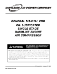
73
I
L
17A
103
102
101
f
98
96
I
__t_
93(oil
fill plug)
(oil drain plug)
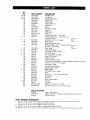
KEY
NO.
/,/ 54
#'./" 55
•/,/ 56
57
58
59
60
61
62
63
64
65
73
•
74
•
/
•
PART NUMBER
CAC-1037
CAC-1038
SSF-991-ZN
CAC-425-1
C-BT-215
SS-10448
SS-391
C-PU-2862
CAC - 142
SSF-8150
CAC- 103
SSF-8111-ZN
SSF-6627
265-25
75
76
77
78
SSF-9821
CAC-291-1
CAC-294
265-196-1
79
80
81
82
83
84
85
86
87
88
•/
89
90
91
v" 92
93
94
95
96
-/
97
98
•/ 100
101
102
103
CAC-289-1
CAC-54-2
CAC-56-1
CAC-58
CAC-57
265-19
CAC-55-1
CAC-207
265-410
SSF-927
265-6
AC-0205
SST-1 O4
265-16-1
SSP-486
DAC-276
SSF-925
AC-0203
SSP-505
SSN-1018
AC-0169
265-2
SSN-1014-ZN
SS-3039-ZN
/
+
+
+
NOT ILLUSTRATED
D20548
CAC-4011-1
D20396
PARTS
ORDERING
•/
+
No.
No.
No.
No.
X
Key
Key
Key
Key
•f,/Key
16,
81,
74,
35,
76,
82,
75,
36,
DESCRIPTION
Throttle screw
Throttle link
Self-tapping screw
Engine 5 HP
Poly-V-Belt
Engine shaft key
Set Screw
Pulley
Belt guard closure
Lock nut
Stiffener bar
Lock nut
Shoulder Stud 3/8" - 16 (2 used)
Intake flapper valve -- square corners
(2 used on head)
O
Screw #5 - 40 x 1/4" (8 used)
Head gasket
Restrictor plate (2 used)
Exhaust flapper valve -- beveled corners
o
(2 used on valve plate)
Valve plate
Valve plate gasket
Compression ring (4 used)
Oil ring (4 used)
Oil ring expander (2 used)
Piston Pin (2 used)
Piston (2 used)
Piston pin plug (4 used)
Connecting rod assembly (2 used) (Includes two SSF-927 screw)
Screw, 1/4 - 20 x 1 1/8" (2 used)
Vent filter (2 used)
Crankcase and cylinder
Ball bearing (2 used)
Base gasket
Oil fill/drain plug (2 used)
Base
I°
Io
Screw 1/4" - 20 x .7/8" Hex (8 used)
Crankshaft
Oil plug
Wavy spring washer
Oil seal
Flywheel
Washer .341/.344 ID 1 1/2" OD
Cap screw, 5/16 - 18 x 3/4" Hex HD Cap
Label, Specification
"Briggs & Stratton" Operating
Owners Manual
and Maintenance
Instructions
INFORMATION
80, 89, 92, 97, and 100, available as individual parts and part of Gasket Kit K-0159
and 83, only available in Ring Kit KK-4313.
and 78, only available in Valve Kit KK-4275.
37, and 38, available in Vibration Mount Kit KK-4282.
Nos. 8, 9, 51, 52, 53, 54, 55, & 56 available individually or in the throttle
control assembly
KK-4486.
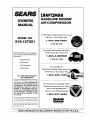
SE,4RS
[RRFTSMRNo
GASOLINE
ENGINE
AIR COMPRESSOR
OWNERS
MANUAL
For the repair or replacement
MODEL
NO.
parts you need
Call 7 am - 7 pro, 7 days a week
1-8OO-366-PART
919.157251
(1-800-366-7278)
For in-home
major
brand repair service
Call 24 hours a day, 7 days a week
When requesting service or ordering
)arts, always provide the following
information:
1-800-4-REPAIR
(1-800-473-7247)
• Model Number
• Part Number
• Part Description
For the location of a
• Name of Item
Sears Parts and Repair Center in yout:rea
Call 24 hours a day, 7 days a wee
FULL ONE YEAR WARRANTY
AIR COMPRESSOR
Ifthis air compressor fails due to a defect in
material or workmanship within one year
from the date of purchase, RETURN IT TO
THE NEAREST SEARS REPAIR CENTER
THROUGHOUT THE UNITED STATES
AND SEARS WILL REPAIR IT, FREE OF
CHARGE. IF PURCHASED FROM ORCHARD SUPPLY HARDWARE, RETURN
TO THE NEAREST ORCHARD STORE
AND ORCHARD WILL REPAIR IT, FREE
OF CHARGE.
1-800-488-1222
For information
Maintenance
on purchasing
Agreement
a Sears
or to inquir--_
_7_...__
__AD_e
call 9 am - 5 pro, Monday-Saturday
about an existing Agreement
___
1-800-827-6655
If t his air compressor is used for commercial
or rental purposes, the warranty will apply
for ninety days from the date of purchase
Roebuck
and Co.,
'_/'_F"
SEARS
This warranty gives you specific legal rights
and you may have other rights which vary
from state to state.
Sears,
_
America
Hoffman
!
_ Repar[ Sp_Clah_
Estates,
IL 60179
U.S.A.