1
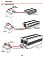
Pure Sine Wave Inverters
R-12-350S/R-24-350S
R-12-700S/R-24-700S
R-12-1000S/R-24-1000S
R-12-1500S/R-24-1500S
R-12-2000S/R-24-2000S
R-12-3000S/R-24-3000S
REDARC PURE SINE INVERTERS
REDARC Pure Sine Wave Inverters produce a pure sine wave output. This means that the power
output from a REDARC Pure Sine Wave Inverter is not only the same as the mains supply... it’s
often better!
WARNING & SAFETY INSTRUCTIONS
This appliance is not intended for use by persons (including children) with reduced physical,
sensory or mental capabilities, or lack of experience and knowledge, unless they are supervised
or have been instructed on how to use the appliance by a person responsible for their safety.
Children should be supervised to ensure that they do not play with the appliance.
Do NOT disassemble the (Product) - the internal circuitry contains hazardous voltages. Attempting
to service the unit yourself may result in electric shock or fire and will void the unit warranty.
Do not expose the inverter to rain, snow, spray, bilge or dust. To reduce the risk of hazard, do
not cover or obstruct the ventilation openings. Do not install the inverter in a zero-clearance
compartment. Overheating may result.
To avoid a risk of fire and/or electronic shock, make sure that existing wiring is in good condition
and not undersized.Do not operate the inverter with damaged or substandard wiring.
Some components in the inverter can cause arcs and sparks. To prevent fire or explosion, do
not put batteries, flammable materials, or anything that should be ignition–protected around the
inverter.
If battery acid contacts skin or clothing, you must wash it out with soap and water immediately.
If battery acid contacts your eyes, you must wash it out with cold running water for at least 20
minutes and get medical attention immediately.
Never smoke or make a spark or flame in the vicinity of the battery or the engine.
Do not drop a metal tool on the battery. The resulting spark or short-circuit on the battery or
other electrical part may cause an explosion.
Remove personal metal items such as rings, bracelets, necklaces, and watches when operating
with a lead-acid batteries.
Failure to do so may cause short circuit and very high temperature, which can melt metal items
and burn your skin.
SAL.FOR.Instruction Manual.Pure Sine Inverters – DOC435 – Version 1
1
CONTENTS
Table of Contents
Warnings and Safety Instructions
Contents
1 Introduction
1. 12V Specifications
2. 24V Specifications
3. Dimensions
2 USER Guide
1. Front Panel Operation
1. Front Panel View
2. On/Off/Remote Switch (700W - 3000W)
3. Input Level LED Display (700W - 3000W)
4. Load Level Display (700W - 3000W)
5. Status LED Displayc (All Models)
6. Power Saving Mode Settings (700W - 3000W)
7. AC Frequency Setting (All Models)
2. Rear Panel Operations
1. Rear Panel View
2. On/Off/Remote Switch (350W Only)
3. Remote Port (700W - 3000W)
4. Ventilation Fan
5. DC Input Terminal (All Models)
6. Chassis Ground
3 INSTALLATION Guide
1. Mounting
2. DC Wiring Connections (700W - 3000W)
1. DC Cable Size
3. Wiring Diagrams
4. DC Cable Connection (700W - 3000W)
1. 700W - 1500W DC Connection method
2. 2000W - 3000W DC Connection method
5. AC Safety Grounding
6. Inverter First Operation
7. Maintenance
4 Troubleshooting
5 Two Year Warranty
2
Page
01
02
03
03
04
05
06
06
06
07
07
07
08
08
09
09
09
10
10
10
11
11
12
12
12
13
14
15
15
15
16
16
16
17
18
1
INTRODUCTION
1.1
12V Specifications
Specification
R-12-350S
R-12-700S
R-12-1000S
R-12-1500S
R-12-2000S
R-12-3000S
Output Power (Cont.)
350W
700W
1000W
1500W
2000W
3000W
Output Power (Max.)
385W
770W
1100W
1650W
2200W
3300W
Surge Rating (Max.)
700W
1400W
2000W
3000W
4000W
6000W
Input Voltage (Nom.)
12V
12V
12V
12V
12V
12V
Input Voltage (Min.)
10.5V
10.5V
10.5V
10.5V
10.5V
10.5V
Input Voltage (Max.)
15V
15V
15V
15V
15V
15V
220/ 230/ 240V AC ± 3%
Output Voltage
50 / 60Hz ± 0.05%
Frequency
Pure Sine Wave (THD < 3%)
Output Waveform
91.0%
91.0%
90.0%
91.0%
90.0%
No Load Current Draw
1.20A
1.25A
1.40A
2.64A
2.80A
Stand-By Current Draw
0.25A
0.25A
0.28A
0.60A
0.55A
Efficiency (full load)
91.0%
10.5V - 15.0V
Input Voltage Regulation
Input Level Indicator
N/A
Red/ Orange/ Green LEDs
Load Level Indicator
N/A
Red/ Orange/ Green LEDs
Red LED
Failure Indicator
Protection
Remote Control Unit
Overload, Short Circuit, Reverse Polarity (Fuse), Over/Under Voltage, Over Temp.
Hardwire
CR-6 12 / CR-8
EN60950-1
Safety Certificate
EMC
EN55022:1997, EN55024: 1997, EN61000-3-2: 1998, EN61000-3-3: 1995
0 - 40°C
Operating Temp.
Cooling
Loading Controlled Cooling Fan
Protection Features for 12V Inverters
Over Voltage Shutdown
15.3V
Over Voltage Restart
14.3V
Under Voltage Alarm
11.0V
Under Voltage Shutdown
10.2V
Under Voltage Restart
12.7V
Over Temperature Shutdown (Interior)
70°C
Over Temperature Restart (Interior)
45°C
Over Temperature Shutdown (Heat Sink)
90°C
Over Temperature Restart (Heat Sink)
60°C
3
1
INTRODUCTION
1.2
24V Specifications
Specification
R-24-350S
R-24-700S
R-24-1000S
R-24-1500S
R-24-2000S
R-24-3000S
Output Power (Cont.)
350W
700W
1000W
1500W
2000W
3000W
Output Power (Max.)
385W
770W
1100W
1650W
2200W
3300W
Surge Rating (Max.)
700W
1400W
2000W
3000W
4000W
6000W
Input Voltage (Nom.)
24V
24V
24V
24V
24V
24V
Input Voltage (Min.)
21.0V
21.0V
21.0V
21.0V
21.0V
21.0V
Input Voltage (Max.)
30V
30V
30V
30V
30V
30V
220/ 230/ 240V AC ± 3%
Output Voltage
50 / 60Hz ± 0.05%
Frequency
Pure Sine Wave (THD < 3%)
Output Waveform
93.0%
94.0%
93.0%
94.0%
93.0%
No Load Current Draw
0.60A
0.65A
0.70A
1.32A
1.50A
Stand-By Current Draw
0.15A
0.15A
0.15A
0.25A
0.35A
Efficiency (full load)
93.0%
21.0 - 30.0V
Input Voltage Regulation
Input Level Indicator
N/A
Red/ Orange/ Green LEDs
Load Level Indicator
N/A
Red/ Orange/ Green LEDs
Red LED
Failure Indicator
Protection
Remote Control Unit
Overload, Short Circuit, Reverse Polarity (Fuse), Over/Under Voltage, Over Temp.
Hardwire
CR-6 24 / CR-8
EN60950-1
Safety Certificate
EMC
EN55022:1997, EN55024: 1997, EN61000-3-2: 1998, EN61000-3-3: 1995
0 - 40°C
Operating Temp.
Cooling
Loading Controlled Cooling Fan
Protection Features for 24V Inverters
Over Voltage Shutdown
30.6V
Over Voltage Restart
28.8V
Under Voltage Alarm
22.0V
Under Voltage Shutdown
20.3V
Under Voltage Restart
25.2V
Over Temperature Shutdown (Interior)
70°C
Over Temperature Restart (Interior)
45°C
Over Temperature Shutdown (Heat Sink)
90°C
Over Temperature Restart (Heat Sink)
60°C
4
1
INTRODUCTION
1.3
Dimensions
F
G
A
E
B
C
D
Dimension
350S
700S
1000S
1500S
2000S
3000S
A
180mm
270mm
340mm
370mm
370mm
400mm
B
125mm
150mm
150mm
160mm
180mm
180mm
C
60mm
70mm
85mm
85mm
165mm
165mm
D
145mm
175mm
180mm
190mm
210mm
210mm
E
132mm
195mm
195mm
195mm
245mm
245mm
F
135mm
160mm
165mm
175mm
195mm
195mm
G
6mm
8mm
8mm
8mm
9mm
9mm
5
2
USER GUIDE
The Redarc pure sine wave power inverter series is one of the most advanced mobile AC power
systems available.
For ideal operation of the power inverter, it must be installed and used properly. Please read
this instruction manual before you install and operate your inverter.
2.1
Front Panel Operation
2.1.1 Front Panel View
Power
Status
350W
Frequency
AC Output
On/Off/Rem.
700W Switch
Input Level
Load Level
Status
1000W
1500W
Frequency
Power Saving
AC Output
On/Off/Rem.
Switch
2000W
3000W
Input Level
Load Level
Status
Frequency
Power Saving
AC Output
6
2
USER GUIDE
2.1.2 On/Off/Remote Switch (700W - 3000W)
This switch acts as an On - Off switch and can also set the unit to remote mode allowing the On
- Off functionality to be performed by either the CR-6 or CR-8 remote control.
Usage:
a.
Before installing the inverter, you need to ensure the main switch is set to “OFF”.
b.
Before using the remote unit, you need to ensure the main switch is set to “REMOTE”.
2.1.3 Input Level LED Display (700W - 3000W)
The Input Level LED Display is designed to advise the user of the DC Input Voltage Level. The
Input Level LED will display the Input Voltage Level using this sequence of flashes and colours
on the LED.
LED Status
RED Slow Blink
RED
ORANGE
GREEN
ORANGE Blink
RED Blink
12V Inverters
24V Inverters
10.3 - 10.6
10.6 - 11.0
11.0 - 12.1
12.1 - 14.2
14.2 - 15.0
> 15.0
20.5 - 21.2
21.2 - 21.8
21.8 - 24.1
24.1 - 28.6
28.6 - 30.0
> 30.3
2.1.4 Load Level Display (700W - 3000W)
The Load Level LED Display is designed to advise the user of the currently supplied AC Wattage.
The Load Level LED will display the Loaded Wattage using this sequence of flashes and colours
on the LED.
LED Status 700W
DARK
0-56W
GREEN
ORANGE
RED
RED Blink
56-230W
230-525W
525-672W
> 672W
1000W
1500W
2000W
3000W
0-80W
80-330W
330-750W
750-960W
> 960W
0-120W
120-495W
495-1125W
1125-1450W
> 1450W
0-160W
160-660W
660-1500W
1500-1920W
> 1920W
0-240W
240-990W
990-2250W
2250-2880W
> 2880W
7
2
USER GUIDE
2.1.5 Status LED Display (All Models)
The Status LED will display Power and Fault Status for the inverter using this sequence of
flashes and colours on the LED.
GREEN LED
Solid
LED Signal
Status
Power OK
Power Saving**
Slow Blink
RED LED
Fast Blink
LED Signal
Status
OVP*
UVP*
OTP*
OLP*
Slow Blink
Intermittent Blink
Solid
*Note: Refer to Troubleshooting (Section 4) for details on status indication.
**Note: Power Saving Mode not available for 350W model.
2.1.6 Power Saving Mode Settings (700W - 3000W)
Power saving mode will trigger when the AC Loaded Wattage (Power Consumption) falls below
the set threshold. The threshold can be set using S1, S2 and S3 on the DIP switch Panel in the
sequences shown on this table.
700W
DISABLE
15W
25W
40W
50W
65W
75W
85W
1000W
1500W
DISABLE
20W
40W
55W
75W
95W
115W
135W
2000W
3000W
DISABLE
40W
80W
125W
170W
210W
245W
280W
S1
Off
On
Off
On
Off
On
Off
On
8
S2
Off
Off
On
On
Off
Off
On
On
S3
Off
Off
Off
Off
On
On
On
On
2
USER GUIDE
2.1.7 AC Frequency Setting (All Models)
This switch will set the output AC Frequency to either 50Hz or 60Hz. For 700W to 3000W
models S4 on the DIP switch is the AC Frequency setting.
2.2
Frequency
Switch
50Hz
60Hz
Off
On
Rear Panel Operations
2.2.1 Rear Panel View
On/Off/Rem.
Switch
350W
DC Input
Terminal
Remote
Port
Ventilation
Fan
Chassis
Ground
700W
1000W
1500W
Remote
Port
Ventilation
Fan
DC Input
Terminal
Chassis
Ground
Ventilation
Fan
2000W
3000W
Remote
Port
DC Input
Terminal
Chassis
Ground
9
2
USER GUIDE
2.2.2 On/Off/Remote Switch (350W Only)
This switch acts as an On - Off switch and can also set the unit to remote mode allowing the On
- Off functionality to be performed by an external switch.
Usage:
a.
Before installing the inverter, you need to ensure the main switch is set to “OFF”.
b.
Before using the remote unit, you need to ensure the main switch is set to “REMOTE”.
Remote Switch Examples
ENB
ON: Inverter On
GND
OFF: Inverter Off
ENB
HIGH: Inverter On
GND
LOW: Inverter Off
2.2.3 Remote Port (700W - 3000W)
Redarc 700W to 3000W inverters are compatible with the CR-6 & CR-8 remote controls.
Before using the remote unit, you need to ensure the main switch is in the “REMOTE” position
and the input voltage of the power inverter is the same as the remote unit.
2.2.4 Ventilation Fan
The fan is load controlled and will engage when the AC Power Consumption reaches a certain
level. Ensure that the fan is not obstructed and is at a distance of at least 25mm from
surrounding objects.
10
2
USER GUIDE
2.2.5 DC Input Terminal (All Models)
•
•
•
Connect DC input terminal to 12V / 24V battery or the other power sources.
POS(+) represents positive, and NEG(-) represents negative.
The Inverter is protected against reverse polarity connection using an internal fuse.
DC Input Voltage
Model
Minimum
10.5
21.0
12V
24V
Maximum
15.0
30.0
2.2.6 Chassis Ground
The Chassis Ground terminal should be connected to the vehicle Chassis using 7.5mm² cable as
a minimum.
WARNING
Operating the inverter without a proper ground connection may cause an electrical
hazard.
11
3
INSTALLATION
3.1
Mounting
The power inverter should be installed in an environment that meets the following requirements:
1. Dry – Do not allow water to drip on or enter into the inverter.
2. Cool – Ambient air temperature should be between 0°C and 40°C, the cooler the better.
3. Safe – Do not install the inverter in a battery compartment or other areas where volatile
fumes may exist, such as fuel storage areas or engine compartments.
4. Ventilated – Keep the inverter a distance (as least 25mm) away from surrounding objects.
Ensure the ventilation shafts on the rear and the bottom of the unit are not obstructed.
5. Dust – Do not install the Inverter in a dusty environments the dust can be inhaled into the unit
when the cooling fan is working.
6. Fused – A fuse must be fitted between the battery and the Inverter.
7. Close to batteries – Avoid excessive cable lengths. Do not install the Inverter in the same
compartment as batteries.
8. Use the recommended wire lengths and sizes (see section 3.2).
9. Do not mount the Inverter where it will be exposed to the gasses produced by the battery.
These gasses are very corrosive, and prolonged exposure will damage the Inverter.
3.2
WARNING
SHOCK HAZARD! Before proceeding further, carefully check that the Inverter is NOT
connected to any batteries, and that all wiring is disconnected from any electrical
sources. Do not connect the output terminals of the Inverter to an incoming AC source.
DC Wiring Connections (700W - 3000W)
Connect cables to the power input terminals on the rear panel of the inverter. The red terminal
represents positive POS(+) and the black terminal represents negative NEG(-). Insert the cables
into the terminals and tighten the screw to clamp the wires securely.
WARNING
Ensure all the DC connections are tight (torque to 11.7 – 13 Nm, 9 – 10 ft-lbs). Loose
connections may cause overheat and fire.
WARNING
The installation of a fuse must be on a positive cable. Failure to place a fuse on “+”
cables running between the inverter and battery may cause damage to the inverter and
will void warranty.
12
3
INSTALLATION
3.2.1 DC Cable Size
The tables below give the recommended cable/conductor cross-sectional area (mm²), and
recommended B & S size for a required current across a particular distance. In this case the
distance is between the battery and the inverter. It is recommended to choose a cable size
close to but larger than required.
NOTE: the cable cross-sectional area will need to be increased, (de-rated), should the cables
be bundled with other heat generating cables, thermally insulated or subjected to high ambient
temperatures.
Distance (m)
mm²
1
2
3
4
5
6
7
8
9
10
Distance (m)
B&S
1
2
3
4
5
6
7
8
9
10
5
1
1
1
1
1
2
2
2
2
2
5
16
16
16
16
16
14
14
14
14
14
10
2
2
2.5
2.5
2.5
2.5
2.5
3.5
3.5
3.5
10
14
14
14
14
14
14
14
12
12
12
20
3.5
3.5
5
5
5
5
5
7.5
7.5
7.5
20
12
12
10
10
10
10
10
8
8
8
30
5
5
5
7.5
7.5
7.5
7.5
10
10
10
Amps (A)
40
50
60
5
5
7.5
5
7.5
10
7.5
7.5
10
7.5
10
10
10
10
16
10
10
16
10
10
16
10
16
16
16
16
25
16
16
25
70
10
10
16
16
16
25
25
25
25
25
80
10
16
16
16
25
25
25
25
25
25
90
16
16
17
25
25
25
23
25
25
35
100
16
16
25
25
25
25
25
25
35
35
30
10
10
10
10
8
8
8
8
8
8
Amps (A)
50
60
10
8
8
8
8
6
8
6
6
6
6
6
6
6
6
4
4
4
4
4
70
8
8
6
6
6
4
4
4
4
4
80
8
6
6
6
4
4
4
4
4
4
90
6
6
6
4
4
4
4
4
4
2
100
6
6
4
4
4
4
4
4
2
2
40
10
10
8
8
8
6
6
6
6
6
13
3
INSTALLATION
3.3
Wiring Diagrams
Fuse or
Circuit Breaker
350W Models
Battery
Fuse or
Circuit Breaker
700W, 1000W &
1500W Models
Battery
Fuse or
Circuit Breaker
2000W & 3000W
Models
Battery
14
3
INSTALLATION
3.4
DC Cable Connection (700W - 3000W)
3.4.1 700W - 1500W DC Connection method
M8 Screw
PVC Wire
Ring Terminal
3.4.2 2000W - 3000W DC Connection method
M8 Nut
Spring Washer
Washer
Ring Terminal
PVC Wire
Plastic Cover
(Black)
Plastic Cover
(Black)
15
3
INSTALLATION
3.5
AC Safety Grounding
Residual Current Devices (RCD)
Certain installation codes and/or government regulations require the installation of a RCD.
Redarc has tested a number of commercially available RCDs and found that they functioned
properly when connected to the output of the Inverter.
NOTE: The AC output ground wire should go to the grounding point for your loads (for example, a
distribution panel ground bus).
3.6
Inverter First Operation
To operate the power inverter, use the ON / OFF switch on the Front panel to turn the power on.
The power inverter is now ready to deliver AC power to your loads. If there is several loads, turn
them on separately after the inverter is “ON” in order to prevent OVP resulted from the surge
power.
1. Set the power switch to the “ON” position, the buzzer will send out “Beep” sounds at this
point. The inverter will now perform self-diagnosis, and the LED indicators will also appear
various colors. Finally the buzzer will “Beep” again and the Input Level and Status LED
indicators will turn “Green” in color, then the inverter starts to work successfully.
2. Set the power switch to the OFF position, the inverter will stop and all the LED’s go off.
3. Set the power inverter switch to the ON position and turn the test load on. The inverter should
supply power to the load. If you plan to accurately measure the true output R.M.S. voltage of
the inverter, a true R.M.S meter must be used to measure the output of the inverter.
3.7
Maintenance
To keep your inverter operating properly, there is very little maintenance required.
You should clean the exterior periodically with a damp cloth to prevent accumulation of dust and
dirt. At the same time, tighten the screws on the DC input terminals.
16
4
TROUBLESHOOTING
Problem or Symptoms
NO AC power output &
Status LED is RED and
Blinking Fast
NO AC power output &
Status LED is RED and
Blinking Slowly
Possible Cause
Over voltage on the
input (OVP)
Low input voltage
(UVP)
NO AC power output &
Status LED is RED and
Blinking Intermittently
Thermal Shutdown
(OTP)
NO AC power output &
Status LED is RED and is
ON Solid
Short circuit or wiring
error. Overload (OLP)
17
Solutions
Check input voltage, ensure
that input is below 14.3V
(28.8V on 24V)
Check input voltage, ensure
that input is above 12.7V
(25.2V on 24V)
Ensure that nothing is
blocking the ventilation fan
at that the ventilation fan is
still operational
Check AC wiring for short
circuit. Reduce the load.
5
TWO YEAR WARRANTY
Our goods come with guarantees that cannot be excluded under the Australian Consumer Law.
You are entitled to a replacement or refund for a major failure and compensation for any other reasonably foreseeable loss or
damage. You are also entitled to have the goods repaired or replaced if the goods fail to be of acceptable quality and the failure
does not amount to a major failure.
The benefits of this Warranty are in addition to other rights and remedies available at law in respect of the
Products and shall not derogate from any applicable mandatory statutory provisions or rights
under the Australian Consumer Law.
Redarc Electronics Pty Ltd atf the Redarc Trust trading as Redarc Electronics (“Redarc
(“Redarc”)
”) offers a warranty in respect of its Products
where the Products are purchased from an authorised distributor or reseller of Redarc by a person (“Purchaser
(“Purchaser”),
”), on the terms and
conditions, and for the duration, outlined below in this document (“
(“Warranty
Warranty”).
”).
1
In this Warranty, the term Products means:
1.1 all products manufactured or supplied by Redarc (excluding its solar
products which are covered by Redarc’s Solar Product Warranty); and
1.2 any component of or accessory for any product in clause 1.1 manufactured
or supplied by Redarc.
Offer and duration of product warranties
2 Redarc warrants that its Products will be free, under normal application,
installation, use and service conditions, from defects in materials and
workmanship affecting normal use, for two (2) years from the date of purchase
(Warranty Period).
3 Where a Product malfunctions or becomes inoperative during the Warranty
Period, due to a defect in materials or workmanship, as determined by Redarc,
then subject to further rights conferred by the Australian Consumer Law on the
Purchaser, Redarc will, in exercise of its sole discretion, either:
3.1 repair the defective Product;
3.2 replace the defective Product; or
3.3 provide a refund to the Purchaser for the purchase price paid for the
defective Product,
without charge to the Purchaser.
4 The warranty given by Redarc in clause 3 covers the costs of delivery and
installation of any repaired or replaced Products or components of Products
to the Purchaser’s usual residential address notified to Redarc, together with
the costs of removal and return of any Products determined by Redarc to be
defective.
Exclusions and limitations
5 This Warranty will not apply to, or include any defect, damage, fault, failure
or malfunction of a Product, which Redarc determines, in exercise of its sole
discretion, to be due to:
5.1 normal wear and tear or exposure to weather conditions over time;
5.2 accident, misuse, abuse, negligence, vandalism, alteration or modification;
5.3 non-observance of any of the instructions supplied by Redarc,
including instructions concerning installation, configuring, connecting,
commissioning, use or application of the Product, including without
limitation choice of location;
5.4 failure to ensure proper maintenance of the Product strictly in accordance
with Redarc’s instructions or failure to ensure proper maintenance of any
associated equipment or machinery;
5.5 repairs to the Product that are not strictly in accordance with Redarc’s
instructions;
5.6 installation, repairs or maintenance of the Product by a person who is not
a qualified auto electrician or electronics technician, or if non-genuine or
non-approved parts have been fitted;
5.7 faulty power supply, power failure, electrical spikes or surges, lightning,
flood, storm, extreme heat, fire or other occurrence outside the control of
Redarc;
5.8 use other than for any reasonable purpose for which the Product was
manufactured;
5.9 any indirect or incidental damage of whatever nature outside the control of
Redarc.
6 Warranty claims in respect of a Product must be made in writing to Redarc at
the postal address or email address specified in clause 20 within the Warranty
Period. Such claims must include the following:
6.1 details of the alleged defect or fault and the circumstances surrounding the
defect or fault;
6.2 evidence of the claim, including photographs of the Product (where the
subject of the claim is capable of being photographed);
6.3 the serial number of the Product, specified on the label affixed to the
Product; and
6.4 proof of purchase documentation for the Product from an authorised
distributor or reseller of Redarc, which clearly shows the date and place of
purchase.
The return of any Products without the prior written instructions of Redarc will
not be accepted by Redarc.
7 Without limiting any other clause in this Warranty, Redarc has the right to reject
any Warranty claim made by a Purchaser pursuant to this Warranty where:
7.1 the Purchaser does not notify Redarc in writing of a Warranty claim within
the Warranty Period;
7.2 the Purchaser does not notify Redarc in writing of a Warranty claim within
one month of becoming aware of the relevant circumstances giving rise to
the claim, so that any further problems with the Product are minimised;
7.3 the serial number of the Product has been altered, removed or made
illegible without the written authority of Redarc;
7.4 the Purchaser is unable to provide proof of purchase documentation in
accordance with clause 6.4 or evidence that the Product was properly
installed and removed (if relevant), and that proper maintenance has been
performed on the Product, by a qualified auto electrician or electronics
technician, in accordance with the instructions of Redarc.
8 If the Product is found to be working satisfactorily on return to Redarc or upon
investigation by Redarc, the Purchaser must pay Redarc’s reasonable costs of
testing and investigating the Product in addition to shipping and transportation
charges. Where Redarc is in possession of the Product, the Product will be
returned to the Purchaser on receipt of the amount charged.
9 Any replaced Products or components of Products shall become the property of
Redarc.
10 Redarc may, in exercise of its sole discretion, deliver another type of Product or
component of a Product (different in size, colour, shape, weight, brand and/or
other specifications) in fulfilling its obligations under this Warranty, in the event
that Redarc has discontinued manufacturing or supplying the relevant Product
or component at the time of the Warranty claim, or where such Product or
component is superior to that originally purchased by the Purchaser.
Other conditions of Warranty
11 If the Purchaser acquired a Product for the purpose of resupply, then this
Warranty shall not apply to that Product.
12 In particular, the sale of a Product via an online auction, online store or other
internet website by a party that is not an authorised distributor or reseller of the
Product will be deemed to be a resupply within the meaning of the Australian
Consumer Law and will render this Warranty void, as Redarc has no control
over the storage, handling, quality or safety of Products sold by such persons.
13 A Purchaser shall only be entitled to the benefit of this Warranty after all
amounts owing in respect of the Product have been paid.
14 While Redarc warrants that the Products will be free from defects in materials
and workmanship in the circumstances set out in this Warranty, to the
maximum extent permitted by law Redarc does not warrant that the operation
of the Products will be uninterrupted or error-free.
15 To the maximum extent permitted by law, Redarc’s determination of the
existence of any defect and the cause of any defect will be conclusive.
16 Spare parts or materials for the Products are guaranteed to be available for a
period of at least two (2) years after purchase of the Products.
17 The agents, officers and employees of any distributor or reseller of the Products
and of Redarc are not authorised to vary or extend the terms of this Warranty.
18 Redarc shall not be responsible or liable to the Customer or any third party in
connection with any non-performance or delay in performance of any terms
and conditions of this Warranty, due to acts of God, war, riots, strikes, warlike
conditions, plague or other epidemic, fire, flood, blizzard, hurricane, changes of
public policies, terrorism and other events which beyond the control of Redarc.
In such circumstances, Redarc may suspend performance of this Warranty
without liability for the period of the delay reasonably attributable to such
causes.
19 If a clause or part of a clause in this Warranty can be read in a way that makes
it illegal, unenforceable or invalid, but can also be read in a way that makes it
legal, enforceable and valid, it must be read in the latter way. If any clause or
part of a clause in this Warranty is illegal, unenforceable or invalid, that clause
or part is to be treated as removed from this Warranty, but the rest of this
Warranty is not affected.
Redarc’s contact details
20 Redarc’s contact details for the sending of Warranty claims under this Warranty
are:
Redarc Electronics Pty Ltd
23 Brodie Road (North), Lonsdale SA 5160
Email: [email protected]
Telephone: +61 8 8322 4848
18
Free technical assistance!
please contact
Redarc Electronics
23 Brodie Road North, Lonsdale SA
(08) 8322 4848
[email protected]
www.redarc.com.au
Copyright © 2012 Redarc Electronics Pty Ltd. All rights reserved.
WARPSINV - REV1
www.redarc.com.au