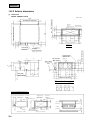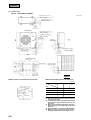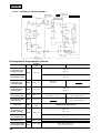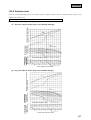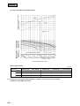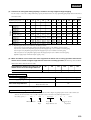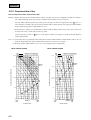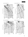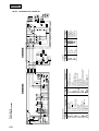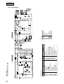
1
FDU-H 15. HIGH STATIC PRESSURE, DUCT TYPE PACKAGED AIRCONDITIONER Split system, Air to air heat pump type ( FDU308HEN-SA 308HES-SA 408HES-SA 508HES-SA 808HES-SA 1008HES-SA ) FDU308HEN-A 308HES-A 408HES-A 508HES-A 508HEM-A 579 FDU-H CONTENTS 15.1 GENERAL INFORMATION ...................................................................... 581 15.1.1 Specific features ................................................................................ 581 15.1.2 How to read the model name............................................................ 581 15.2 SELECTION DATA ................................................................................... 582 15.2.1 Specifications .................................................................................... 582 15.2.2 Range of usage & limitations ........................................................... 593 15.2.3 Exterior dimensions .......................................................................... 594 15.2.4 Exterior appearance .......................................................................... 603 15.2.5 Piping system .................................................................................... 604 15.2.6 Selection chart ................................................................................... 607 15.2.7 Characteristics of fan ........................................................................ 610 15.2.8 Noise level .......................................................................................... 613 15.3 ELECTRICAL DATA ................................................................................. 615 15.3.1 Electrical wiring ................................................................................. 615 15.4 OUTLINE OF OPERATION CONTROL BY MICROCOMPUTER ............ 623 15.5 APPLICATION DATA................................................................................ 623 15.5.1 Installation of indoor unit ................................................................. 624 15.5.2 Installation of remote controller....................................................... 626 15.5.3 Installation of outdoor unit ............................................................... 626 15.6 MAINTENANCE DATA ............................................................................. 626 580 FDU-H 15.1 GENERAL INFORMATION 15.1.1 Specific features (1) Less refrigerant charge amount due to use of double phase refrigerant flow system. The total refrigerant charge amount has been reduced by more than 50%. (2) The indoor outdoor interconnection signal wiring has been done away with. The microcomputer chip is installed in the indoor unit. There is no need for the unit to communicate between the outdoor and indoor units so the unit is more resistant to electromagnetic noise thus the incidence of microcomputer malfunction has been reduced. The compressor in the outdoor unit has its own self protection function, that reacts according to abnormal high pressure and excessive high temperature. (3) There are only five power lines between the outdoor and indoor unit, As no signal wire is used there is no need to separate the power line from the signal line. One cab tyre cable with 6 wires encased in one sheath is enough for conducting the wiring work between the outdoor unit and the indoor unit. This contributes to simpler wiring work in the field. (4) All models have control valves protruding from the outdoor unit for faster flare connection work in the field. (5) Operation noise has been drastically reduced by increasing the number of high performance fans and by through sound insulation. (6) When installing, the optimum outside static pressure can be set using the fan controller. (7) With the height of all equipment made uniform at 360mm and neatly installed into the ceiling, the installation of equipment with different capacities into the same ceiling space is made easy. 15.1.2 How to read the model name Example: FDU 30 8 H EN-SA Applicable power source ... See the specifications Heat pump type Series No. Product capacity Model name FDU: High static pressure duct type wired remote controller FDC: Outdoor unit 581 FDU-H 15.2 SELECTION DATA 15.2.1 Specifications Model FDU308HEN-SA FDU308HEN-SA Model Item FDU308-A Nominal cooling capacity(1) W Nominal heating capacity(1) W FDC308HEN3 7100 8000 Power source Cooling input Operation data(3) Running current (Cooling) Power factor (Cooling) 1 Phase, 220/240V, 50Hz kW 3.20/3.40 A 14.8/15.4 % 98/92 kW 3.06/3.22 Running current (Heating) A 14.2/14.7 Power factor (Heating) % 98/91 Inrush current (L.R.A) A Heating input Noise level Exterior dimensions Height × Width × Depth Net weight 95 dB(A) 41 52 mm 360 × 820 × 830 845× 880× 340 kg 48 74 – GT-A5534EN41 × 1 Refrigerant equipment Compressor type & Q’ty Motor kW Starting method Heat exchanger – 2.5 – Line starting Louver fines & inner grooved tubing Refrigerant control Slitted fins & bare tubing Capillary tube Refrigerant R22 Quantity Refrigerant oil kg Holding charged r – 1.4 [Pre-charged up to the piping length of 5m] 1.45 (BARREL FREEZE 32SAM) Defrost control MC controlled de-icer High pressure control High pressure switch Air handling equipment Multiblade centrifugal fan × 2 Fan type & Q’ty Motor 130 × 1 55 × 1 Line starting Line starting 20 58 Standard: 100 (10), Max: 200 (20) – W Starting method Air flow (Standard) Available static pressure CMM Pa (mmAq) Propeller fan × 1 Fresh air intake Available – Air filter, Q’ty Field purchased – Rubber sleeve (for fan motor) Rubber mount (for compressor) – 33(Crank case heater) Shock & vibration absorber Electric heater W Operation control Wired remote control switch Operation switch (Optional: RCD-H-E) Room temperature control Safety equipment Installation data Refrigerant piping size – (Indoor unit side) Thermostat by electronics Internal thermostat for fan motor. Frost protection thermostat. Abnormal discharge temperature protection. mm Liquid line: φ9.52 (3/8″) Gas line: φ15.88 (5/8″) (in) Connecting method Drain hose – Internal thermostat for fan motor. Flare piping (Connectable with VP25) Insulation for piping Accessories – Necessary (both Liquid & Gas lines) Mounting kit. Optional parts Notes (1) The data are measured at the following conditions. Item Indoor air temperature Operation DB WB Cooling 27˚C 19˚C Heating 20˚C – – Outdoor air temperature DB WB 35˚C 24˚C 7˚C 6˚C (2) This packaged air-conditioner is manufactured and tested in conformity with the following standard. JIS B8616 “UNITARY AIR-CONDITIONERS” (3) The operation data indicate when the air-conditioner is operated at 220/240V 50Hz. 582 Standards ISO-T1, JIS B8616 FDU-H Model FDU308HES-SA FDU308HES-SA Model Item FDU308-A Nominal cooling capacity(1) Nominal heating capacity(1) Power source Cooling input Running current (Cooling) Power factor (Cooling) Heating input Running current (Heating) Power factor (Heating) Inrush current (L.R.A) Noise level Exterior dimensions Height × Width × Depth Net weight Refrigerant equipment Compressor type & Q’ty Motor Starting method Heat exchanger Refrigerant control Refrigerant Quantity Operation data(3) kW A % kW A % A dB(A) 41 52 mm 360 × 820 × 830 845 × 880 × 340 kg 48 74 – GT-A5534ES41 × 1 – 2.5 – Line starting Louver fins & inner grooved tubing Slitted fins & bare tubing Capillary tube R22 Holding charged 1.4 [Pre-charged up to the piping length of 5m] kW kg r Refrigerant oil Defrost control High pressure control Air handling equipment Fan type & Q’ty Motor Starting method Air flow (Standard) Available static pressure – CMM Pa (mmAq) W thermostat for fan motor. Installation data Refrigerant piping size Connecting method Drain hose Insulation for piping Accessories Optional parts 1.45 (BARREL FREEZE 32SAM) MC controlled de-icer High pressure switch Multiblade centrifugal fan × 2 Propeller fan × 1 130 × 1 Line starting 20 55 × 1 Line starting 58 Standard: 100 (10), Max 200 (20) – W Fresh air intake Air filter, Q’ty Shock & vibration absorber Electric heater Operation control Operation switch Room temperature control Safety equipment FDC308HES3 7100 8000 3 Phase, 380/415V 50Hz 3.12/3.18 5.7/6.2 83/72 2.76/2.82 5.2/5.5 8.1/7.2 45 W W Available Field purchased Rubber sleeve (for fan motor) – Wired remote control switch (Optional: RCD-H-E) Thermostat by electronics Internal thermostat for fan motor. – (Indoor unit side) – Internal thermostat for fan motor. Frost protection thermostat. Abnormal discharge temperature protection. mm (in) – – Rubber mount (for compressor) 33 (Crank case heater) nternal Liquid line: φ9.52 (3/8″) Gas line: φ15.88 (5/8″) Flare piping (Connectable with VP25) Necessary (both Liquid & Gas lines) Mounting kit. – – Notes (1) The data are measured at the following conditions. Item Indoor air temperature Outdoor air temperature Operation Cooling DB 27˚C WB 19˚C DB 35˚C WB 24˚C Heating 20˚C – 7˚C 6˚C Standards ISO-T1, JIS B8616 (2) This packaged air-conditioner is manufactured and tested in conformity with the following standard. JIS B8616 “UNITARY AIR-CONDITIONERS” (3) The operation data indicate when the air-conditioner is operated at 380/415V 50Hz. 583 FDU-H Model FDU408HES-SA FDU408HES-SA Model Item FDU408-A Nominal cooling capacity(1) Nominal heating capacity(1) Power source Cooling input Running current (Cooling) Power factor (Cooling) Heating input Running current (Heating) Power factor (Heating) Inrush current (L.R.A) Noise level Exterior dimensions Height × Width × Depth Net weight Refrigerant equipment Compressor type & Q’ty Motor Starting method Heat exchanger Refrigerant control Refrigerant Quantity Operation data(3) kW A % kW A % A dB(A) 44 54 mm 360 × 820 × 830 1050 × 920 × 340 kg 49 90 – GU-A5550ES41 × 1 kW kg – 2.8 – Line starting Louver fins & inner grooved tubing Slitted fins & bare tubing Capillary tube R22 Holding charged 1.7 [Pre-charged up to the piping length of 5m] r Refrigerant oil Defrost control High pressure control Air handling equipment Fan type & Q’ty Motor Starting method Air flow (Standard) Available static pressure – CMM Pa (mmAq) W 1.6 (BARREL FREEZE 32SAM) MC controlled de-icer High pressure switch Multiblade centrifugal fan × 2 Propeller fan × 2 200 × 1 Line starting 27 40 × 2 Line starting 70 Standard: 100 (10), Max 200 (20) – W Fresh air intake Air filter, Q’ty Shock & vibration absorber Electric heater Operation control Operation switch Room temperature control Safety equipment FDC408HES3 10000 11200 3 Phase, 380/415V 50Hz 4.68/4.78 8.1/8.4 87/79 4.06/4.10 7.4/7.8 83/73 53 W W Available Field purchased Rubber sleeve (for fan motor) – Wired remote control switch (Optional: RCD-H-E) Thermostat by electronics Internal thermostat for fan motor. – – Rubber mount (for compressor) 40 (Crank case heater) – (Indoor unit side) – Internal thermostat for fan motor. Inter- nal thermostat for fan motor. Frost protection thermostat. Abnormal discharge temperature protection. Installation data mm Liquid line: φ9.52 (3/8″) Gas line: φ19.05 (3/4″) Refrigerant piping size (in) Connecting method Flare piping Drain hose (Connectable with VP25) – Insulation for piping Necessary (both Liquid & Gas lines) Accessories Mounting kit. Optional parts – Notes (1) The data are measured at the following conditions. Item Indoor air temperature Outdoor air temperature Operation Cooling DB 27˚C WB 19˚C DB 35˚C WB 24˚C Heating 20˚C – 7˚C 6˚C (2) This packaged air-conditioner is manufactured and tested in conformity with the following standard. JIS B8616 “UNITARY AIR-CONDITIONERS” (3) The operation data indicate when the air-conditioner is operated at 380/415V 50Hz. 584 Standards ISO-T1, JIS B8616 FDU-H Model FDU508HES-SA FDU508HES-SA Model Item FDU508-A Nominal cooling capacity(1) Nominal heating capacity(1) Power source Cooling input Running current (Cooling) Power factor (Cooling) Heating input Running current (Heating) Power factor (Heating) Inrush current (L.R.A) Noise level Exterior dimensions Height × Width × Depth Net weight Refrigerant equipment Compressor type & Q’ty Motor Starting method Heat exchanger Refrigerant control Refrigerant Quantity Operation data(3) kW A % kW A % A dB(A) 45 55 mm 360 × 1200 × 830 1250 × 920 × 340 kg 62 101 – GU-A5570ES41 × 1 kW kg – 3.75 – Line starting Louver fins & inner grooved tubing Slitted fins & bare tubing Capillary tube R22 Holding charged 1.9 [Pre-charged up to the piping length of 5m] r Refrigerant oil Defrost control High pressure control Air handling equipment Fan type & Q’ty Motor Starting method Air flow (Standard) Available static pressure – CMM Pa (mmAq) W 1.6 (BARREL FREEZE 32SAM) MC controlled de-icer High pressure switch Multiblade centrifugal fan × 2 Propeller fan × 2 230 × 1 Line starting 34 65 × 2 Line starting 110 Standard: 100 (10), Max 200 (20) – W Fresh air intake Air filter, Q’ty Shock & vibration absorber Electric heater Operation control Operation switch Room temperature control Safety equipment FDC508HES3 12500 14000 3 Phase, 380/415V 50Hz 5.44/5.71 9.8/10.6 84/75 4.99/5.14 9.3/10.2 82/70 74 W W Available Field purchased Rubber sleeve (for fan motor) – Wired remote control switch (Optional: RCD-H-E) Thermostat by electronics Internal thermostat for fan motor. – – Rubber mount (for compressor) 40 (Crank case heater) – (Indoor unit side) – Internal thermostat for fan motor. Inter- nal thermostat for fan motor. Frost protection thermostat. Abnormal discharge temperature protection. Installation data mm Liquid line: φ9.52 (3/8″) Gas line: φ19.05 (3/4″) Refrigerant piping size (in) Connecting method Flare piping Drain hose (Connectable with VP25) – Insulation for piping Necessary (both Liquid & Gas lines) Accessories Mounting kit. Optional parts – Notes (1) The data are measured at the following conditions. Item Indoor air temperature Outdoor air temperature Operation Cooling DB 27˚C WB 19˚C DB 35˚C WB 24˚C Heating 20˚C – 7˚C 6˚C Standards ISO-T1, JIS B8616 (2) This packaged air-conditioner is manufactured and tested in conformity with the following standard. JIS B8616 “UNITARY AIR-CONDITIONERS” (3) The operation data indicate when the air-conditioner is operated at 380/415V 50Hz. 585 FDU-H Model FDU808HES-SA FDU808HES-SA Model Item FDU808-A Nominal cooling capacity(1) W Nominal heating capacity(1) W FDC808HES3 20000 21200 Power source Cooling input Operation data(3) Running current (Cooling) Power factor (Cooling) 3 Phase, 380/415V 50Hz kW 9.1/9.2 A 16.2/15.5 % 85/83 kW 7.1/7.3 Running current (Heating) A 13.6/13.2 Power factor (Heating) % 79/77 Inrush current (L.R.A) A Heating input Noise level Exterior dimensions Height × Width × Depth Net weight 99 dB(A) 48 58 mm 360 × 1570 × 830 1450 × 1350 × 600 kg 92 185 – CB90 × 1 Refrigerant equipment Compressor type & Q’ty Motor kW Starting method Heat exchanger – 6.5 – Line starting Louver fines & inner grooved tubing Refrigerant control Slitted fines & bare tubing Capillary tube Refrigerant R22 Quantity Refrigerant oil kg Holding charged r – 5.33 [Pre-charged up to the piping length of 5m] 4.4 (BARREL FREEZE 32SAM) Defrost control MC controlled de-icer High pressure control High pressure switch Air handling equipment Multiblade centrifugal fan × 4 Fan type & Q’ty Motor 200 × 2 100 × 2 Line starting Line starting 51 180 Standard: 100 (10), Max: 200 (20) – Available – W Starting method Air flow (Standard) Available static pressure CMM Pa (mmAq) Fresh air intake Air filter, Q’ty Shock & vibration absorber Electric heater Rubber mount (for compressor) – 70 (Crank case heater) (Optional: RCD-H-E) Room temperature control – Internal thermostat for fan motor. Internal thermostat for fan motor Frost protection thermostat. High pressure protection switch mm Liquid line: φ12.7 (1/2″) Gas line: φ25.4 (1″) (in) Connecting method Drain hose – (Indoor unit side) Thermostat by electronics Safety equipment Refrigerant piping size – Rubber sleeve (for fan motor) Wired remote control switch Operation switch Installation data Field purchased W Operation control Propeller fan × 2 Brazing Liquid line: Flare Gas line: Brazing (Connectable with VP25) Insulation for piping Accessories – Necessary (both Liquid & Gas lines) Mounting kit. Optional parts Notes (1) The data are measured at the following conditions. Item Indoor air temperature Operation DB WB Cooling 27˚C 19˚C Heating 20˚C – – Outdoor air temperature DB WB 35˚C 24˚C 7˚C 6˚C (2) This packaged air-conditioner is manufactured and tested in conformity with the following standard. JIS B8616 “UNITARY AIR-CONDITIONERS” (3) The operation data indicate when the air-conditioner is operated at 380/415V 50Hz. 586 Standards ISO-T1, JIS B8616 FDU-H Model FDU1008HES-SA FDU1008HES-SA Model Item FDU1008-A Nominal cooling capacity(1) W Nominal heating capacity(1) W FDC1008HES3 25000 28000 Power source Operation data(3) Cooling input Running current (Cooling) Power factor (Cooling) 3 Phase, 380/415V 50Hz kW 12.8/12.9 A 22.7/21.7 % 86/83 kW 10.6/10.8 Running current (Heating) A 19.2/18.7 Power factor (Heating) % 84/80 Inrush current (L.R.A) A Heating input Noise level Exterior dimensions Height × Width × Depth Net weight 154 dB(A) 49 58 mm 360 × 1570 × 830 1450 × 1350 × 600 kg 92 195 – CB125 × 1 Refrigerant equipment Compressor type & Q’ty Motor kW Starting method Heat exchanger – 9.0 – Line starting Louver fines & inner grooved tubing Refrigerant control Slitted fines & bare tubing Capillary tube Refrigerant R22 Quantity Refrigerant oil kg Holding charged r – 7.6 [Pre-charged up to the piping length of 5m] 4.4 (BARREL FREEZE 32SAM) Defrost control MC controlled de-icer High pressure control High pressure switch Air handling equipment Multiblade centrifugal fan × 4 Fan type & Q’ty Motor W 230 × 1, 270 × 1 100 × 2 Line starting Line starting 68 180 Standard: 100 (10), Max: 200 (20) – Available – Starting method Air flow (Standard) Available static pressure CMM Pa (mmAq) Fresh air intake Air filter, Q’ty Shock & vibration absorber Electric heater Rubber mount (for compressor) – 70 (Crank case heater) (Optional: RCD-H-E) Room temperature control – Internal thermostat for fan motor. Internal thermostat for fan motor Frost protection thermostat. High pressure protection switch mm Liquid line: φ15.88 (5/8″) Gas line: φ28.58 (1 1/8″) (in) Connecting method Drain hose – (Indoor unit side) Thermostat by electronics Safety equipment Refrigerant piping size – Rubber sleeve (for fan motor) Wired remote control switch Operation switch Installation data Field purchased W Operation control Propeller fan × 2 Brazing Liquid line: Flare Gas line: Brazing (Connectable with VP25) Insulation for piping Accessories – Necessary (both Liquid & Gas lines) Mounting kit. Optional parts Notes (1) The data are measured at the following conditions. Item Indoor air temperature Operation DB WB Cooling 27˚C 19˚C Heating 20˚C – – Outdoor air temperature DB WB 35˚C 24˚C 7˚C 6˚C Standards ISO-T1, JIS B8616 (2) This packaged air-conditioner is manufactured and tested in conformity with the following standard. JIS B8616 “UNITARY AIR-CONDITIONERS” (3) The operation data indicate when the air-conditioner is operated at 380/415V 50Hz. 587 FDU-H Model FDU308HEN-A FDU308HEN-A Model Item FDU308-A Nominal cooling capacity(1) W Nominal heating capacity(1) W FDC306HEN3 7100 7300 Power source Cooling input Operation data(3) Running current (Cooling) Power factor (Cooling) 1 Phase, 220/240V, 50Hz kW 3.29/3.33 A 16.5/17.3 % 91/80 kW 3.04/3.08 Running current (Heating) A 15.4/16.2 Power factor (Heating) % 90/79 Inrush current (L.R.A) A Heating input Noise level Exterior dimensions Height × Width × Depth Net weight 89 dB(A) 41 56 mm 360 × 820 × 830 844 × 950 × 340 kg 48 69 – RC5532ENE1 × 1 Refrigerant equipment Compressor type & Q’ty Motor kW Starting method Heat exchanger – 2.24 – Line starting Louver fines & inner grooved tubing Refrigerant control Slitted fins & bare tubing Capillary tube Refrigerant R22 Quantity Refrigerant oil kg Holding charged r – 1.3 [Pre-charged up to the piping length of 5m] 1.63 (SUNISO 3GS) Defrost control IC controlled de-icer High pressure control High pressure regulator valve Air handling equipment Multiblade centrifugal fan × 2 Fan type & Q’ty Motor 130 × 1 60 × 1 Line starting Line starting 20 54 Standard: 100 (10), Max: 200 (20) – W Starting method Air flow (Standard) Available static pressure CMM Pa (mmAq) Propeller fan × 1 Fresh air intake Available – Air filter, Q’ty Field purchased – Rubber sleeve (for fan motor) Rubber mount (for compressor) – 40 (Crank case heater) Shock & vibration absorber Electric heater W Operation control Wired remote control switch Operation switch Room temperature control Safety equipment (Optional: RCD-H-E) – (Indoor unit side) Thermostat by electronics – Internal protector for compressor. Internal thermostat for fan motor. Internal pressure relief valve for compressor. Internal thermostat for fan motor. Frost protection thermostat. Installation data Refrigerant piping size mm Liquid line: φ9.52 (3/8″) Gas line: φ15.88 (5/8″) (in) Connecting method Drain hose Flare piping (Connectable with VP25) Insulation for piping Accessories – Necessary (both Liquid & Gas lines) Mounting kit. Optional parts Notes (1) The data are measured at the following conditions. Item Indoor air temperature Operation DB WB Cooling 27˚C 19˚C Heating 20˚C – – Outdoor air temperature DB WB 35˚C 24˚C 7˚C 6˚C (2) This packaged air-conditioner is manufactured and tested in conformity with the following standard. JIS B8616 “UNITARY AIR-CONDITIONERS” (3) The operation data indicate when the air-conditioner is operated at 220/240V 50Hz. 588 Standards ISO-T1, JIS B8616 FDU-H Model FDU308HES-A FDU308HES-A Model Item FDU308-A Nominal cooling capacity(1) (1) FDC306HES3 7100/7700 6000 7300/7900 3 Phase, 380-415V 50Hz, 380V 60Hz 3.05/3.06/3.64 5.9/6.0/7.1 79/71/78 2.72/2.74/3.19 5.5/5.7/6.7 75/67/72 3.87 7.6 77 43 41/43 56 W W ISO-T1 kW A % kW A % kW A % A dB(A) ISO-T3 Operation data(3) Nominal heating capacity Power source Cooling input Running current (Cooling) Power factor (Cooling) Heating input Running current (Heating) Power factor (Heating) Cooling input Running current (Cooling) Power factor (Cooling) Inrush current (L.R.A) Noise level Exterior dimensions Height × Width × Depth Net weight Refrigerant equipment Compressor type & Q’ty Motor Starting method Heat exchanger Refrigerant control Refrigerant Quantity Refrigerant oil Defrost control High pressure control Air handling equipment Fan type & Q’ty Motor Starting method Air flow (Standard) Available static pressure ISO-T1 ISO-T3 ISO-T1 mm 360 × 820 × 830 844 × 950 × 340 kg 48 69 – RC5538ESE1 × 1 – 2.24 – Line starting Louver fins & inner grooved tubing Slitted fins & bare tubing Capillary tube R22 Holding charged 1.3 [Pre-charged up to the piping length of 5m] – 1.63 (SUNISO 3GS) IC controlled de-icer High pressure regulator valve kW kg r Multiblade centrifugal fan × 2 Propeller fan × 1 130 × 1 Line starting 20/24 60 × 1 Line starting 54/56 Standard: 100 (10), Max 200 (20) – W CMM Pa (mmAq) Fresh air intake Air filter, Q’ty Shock & vibration absorber Electric heater Operation control Operation switch Room temperature control Safety equipment W Installation data Refrigerant piping size Connecting method Drain hose Insulation for piping Accessories Optional parts Available Field purchased Rubber sleeve (for fan motor) – Wired remote control switch (Optional: RCD-H-E) Thermostat by electronics Internal thermostat for fan motor. Frost protection thermostat. mm (in) – – Rubber mount (for compressor) 40 (Crank case heater) – (Indoor unit side) – Internal protector for compressor. Internal thermostat for fan motor. Internal thermostat for fan motor. Internal pressure relief valve for compressor. Liquid line: φ9.52 (3/8″) Gas line: φ15.88 (5/8″) Flare piping (Connectable with VP25) Necessary (both Liquid & Gas lines) Mounting kit. – – Notes (1) The data are measured at the following conditions. Item Operation Cooling Heating Indoor air temperature Outdoor air temperature Standards DB WB DB WB 27˚C 20˚C 19˚C – 35˚C 7˚C 24˚C 6˚C ISO-T1, JIS B8616 24˚C ISO-T3, SASO Cooling 29˚C 19˚C 46˚C (2) This packaged air-conditioner is manufactured and tested in conformity with the following standard. JIS B8616 “UNITARY AIR-CONDITIONERS” (3) The operation data indicate when the air-conditioner is operated at 380V 50Hz/415V 50Hz/380V 60Hz. 589 FDU-H Model FDU408HES-A FDU408HES-A Model Item FDU408-A Nominal cooling capacity(1) (1) FDC406HES3 10200/11300 9900 10500/11600 3 Phase, 380-415V 50Hz, 380V 60Hz 3.96/3.96/4.88 7.8/7.8/9.4 77/71/79 3.66/3.66/4.51 7.5/7.5/9.1 74/68/75 5.38 10.1 81 45 44/46 57 W W ISO-T1 kW A % kW A % kW A % A dB(A) ISO-T3 Operation data(3) Nominal heating capacity Power source Cooling input Running current (Cooling) Power factor (Cooling) Heating input Running current (Heating) Power factor (Heating) Cooling input Running current (Cooling) Power factor (Cooling) Inrush current (L.R.A) Noise level Exterior dimensions Height × Width × Depth Net weight Refrigerant equipment Compressor type & Q’ty Motor Starting method Heat exchanger Refrigerant control Refrigerant Quantity Refrigerant oil Defrost control High pressure control Air handling equipment Fan type & Q’ty Motor Starting method Air flow (Standard) Available static pressure ISO-T1 ISO-T3 ISO-T1 mm 360 × 820 × 830 1250 × 950 × 340 kg 49 86 – RC5547ESE1 × 1 – 2.61 – Line starting Louver fins & inner grooved tubing Slitted fins & bare tubing Capillary tube R22 Holding charged 1.6 [Pre-charged up to the piping length of 0m] – 1.63 (SUNISO 3GS) IC controlled de-icer High pressure regulator valve kW kg r Multiblade centrifugal fan × 2 Propeller fan × 2 200 × 1 Line starting 27/32 60 × 2 Line starting 100/110 Standard: 100 (10), Max 200 (20) – W CMM Pa (mmAq) Fresh air intake Air filter, Q’ty Shock & vibration absorber Electric heater Operation control Operation switch Room temperature control Safety equipment W Installation data Refrigerant piping size Connecting method Drain hose Insulation for piping Accessories Optional parts Available Field purchased Rubber sleeve (for fan motor) – Wired remote control switch (Optional: RCD-H-E) Thermostat by electronics Internal thermostat for fan motor. Frost protection thermostat. mm (in) – – Rubber mount (for compressor) 40 (Crank case heater) – (Indoor unit side) – Internal protector for compressor. Internal thermostat for fan motor. Internal thermostat for fan motor. Internal pressure relief valve for compressor. Liquid line: φ9.52 (3/8″) Gas line: φ19.05 (3/4″) Flare piping (Connectable with VP25) Necessary (both Liquid & Gas lines) Mounting kit. – – Notes (1) The data are measured at the following conditions. Item Operation Cooling Heating Indoor air temperature Outdoor air temperature WB DB WB 27˚C 20˚C 19˚C – 35˚C 7˚C 24˚C 6˚C ISO-T1, JIS B8616 24˚C ISO-T3, SASO Cooling 29˚C 19˚C 46˚C (2) This packaged air-conditioner is manufactured and tested in conformity with the following standard. JIS B8616 “UNITARY AIR-CONDITIONERS” (3) The operation data indicate when the air-conditioner is operated at 380V 50Hz/415V 50Hz/380V 60Hz. 590 Standards DB FDU-H Model FDU508HES-A FDU508HES-A Model Item FDU508-A Nominal cooling capacity(1) (1) FDC506HES3 12500/14000 11900 12800/14400 3 Phase, 380-415V 50Hz, 380V 60Hz 5.01/5.03/6.03 10.3/10.3/11.5 74/68/80 4.63/4.67/5.61 9.5/9.6/10.7 74/68/80 6.63 12.5 81 68 45/47 59 W W ISO-T1 kW A % kW A % kW A % A dB(A) ISO-T3 Operation data(3) Nominal heating capacity Power source Cooling input Running current (Cooling) Power factor (Cooling) Heating input Running current (Heating) Power factor (Heating) Cooling input Running current (Cooling) Power factor (Cooling) Inrush current (L.R.A) Noise level Exterior dimensions Height × Width × Depth Net weight Refrigerant equipment Compressor type & Q’ty Motor Starting method Heat exchanger Refrigerant control Refrigerant Quantity Refrigerant oil Defrost control High pressure control Air handling equipment Fan type & Q’ty Motor Starting method Air flow (Standard) Available static pressure ISO-T1 ISO-T3 ISO-T1 mm 360 × 1200 × 830 1250 × 950 × 340 kg 62 91 – RC5563ESE2 × 1 – 3.73 – Line starting Louver fins & inner grooved tubing Slitted fins & bare tubing Capillary tube R22 Holding charged 2.3 [Pre-charged up to the piping length of 5m] – 2.07 (SUNISO 3GS) IC controlled de-icer High pressure regulator valve kW kg r Multiblade centrifugal fan × 2 Propeller fan × 2 230 × 1 Line starting 34/40 60 × 2 Line starting 100/110 Standard: 100 (10), Max 200 (20) – W CMM Pa (mmAq) Fresh air intake Air filter, Q’ty Shock & vibration absorber Electric heater Operation control Operation switch Room temperature control Safety equipment W Installation data Refrigerant piping size Connecting method Drain hose Insulation for piping Accessories Optional parts Available Field purchased Rubber sleeve (for fan motor) – Wired remote control switch (Optional: RCD-H-E) Thermostat by electronics Internal thermostat for fan motor. Frost protection thermostat. mm (in) – – Rubber mount (for compressor) 40 (Crank case heater) – (Indoor unit side) – Internal protector for compressor. Internal thermostat for fan motor. Internal thermostat for fan motor. Internal pressure relief valve for compressor. Liquid line: φ9.52 (3/8″) Gas line: φ19.05 (3/4″) Flare piping (Connectable with VP25) Necessary (both Liquid & Gas lines) Mounting kit. – – Notes (1) The data are measured at the following conditions. Item Operation Cooling Heating Indoor air temperature Outdoor air temperature Standards DB WB DB WB 27˚C 20˚C 19˚C – 35˚C 7˚C 24˚C 6˚C ISO-T1, JIS B8616 24˚C ISO-T3, SASO Cooling 29˚C 19˚C 46˚C (2) This packaged air-conditioner is manufactured and tested in conformity with the following standard. JIS B8616 “UNITARY AIR-CONDITIONERS” (3) The operation data indicate when the air-conditioner is operated at 380V 50Hz/415V 50Hz/380V 60Hz. 591 FDU-H Model FDU508HEM-A FDU508HEM-A Model Item FDU508-A Nominal cooling capacity(1) (1) ISO-T1 ISO-T3 Operation data(3) Nominal heating capacity Power source Cooling input Running current (Cooling) Power factor (Cooling) Heating input Running current (Heating) Power factor (Heating) Cooling input Running current (Cooling) Power factor (Cooling) Inrush current (L.R.A) Noise level Exterior dimensions Height × Width × Depth Net weight Refrigerant equipment Compressor type & Q’ty Motor Starting method Heat exchanger Refrigerant control Refrigerant Quantity Refrigerant oil Defrost control High pressure control Air handling equipment Fan type & Q’ty Motor Starting method Air flow (Standard) Available static pressure ISO-T1 ISO-T3 ISO-T1 W W kW A % kW A % kW A % A dB(A) 45/47 59 mm 360 × 1200 × 830 1250 × 950 × 340 kg 62 91 – RC5563EME2 × 1 – 3.75 – Line starting Louver fins & inner grooved tubing Slitted fins & bare tubing Capillary tube R22 Holding charged 2.3 [Pre-charged up to the piping length of 5m] – 2.07 (SUNISO 3GS) IC controlled de-icer High pressure regulator valve kW kg r Multiblade centrifugal fan × 2 Propeller fan × 2 230 × 1 Line starting 34/40 60 × 2 Line starting 100/110 Standard: 100 (10), Max 200 (20) – W CMM Pa (mmAq) Fresh air intake Air filter, Q’ty Shock & vibration absorber Electric heater Operation control Operation switch Room temperature control Safety equipment W Installation data Refrigerant piping size Connecting method Drain hose Insulation for piping Accessories Optional parts FDC506HEM3 12500/14000 11900 12800/14400 3 Phase, 230V 50Hz, 220V 60Hz 5.01/6.03 15.1/18.5 83/86 4.70/5.61 14.0/17.1 84/86 6.62 20.0 87 133 Available Field purchased Rubber sleeve (for fan motor) – Wired remote control switch (Optional: RCD-H-E) Thermostat by electronics Internal thermostat for fan motor. Frost protection thermostat. mm (in) – – Rubber mount (for compressor) 40 (Crank case heater) – (Indoor unit side) – Internal protector for compressor. Internal thermostat for fan motor. Internal thermostat for fan motor. Internal pressure relief valve for compressor. Liquid line: φ9.52 (3/8″) Gas line: φ19.05 (3/4″) Flare piping (Connectable with VP25) Necessary (both Liquid & Gas lines) Mounting kit. – – Notes (1) The data are measured at the following conditions. Item Operation Cooling Heating Indoor air temperature Outdoor air temperature WB DB WB 27˚C 20˚C 19˚C – 35˚C 7˚C 24˚C 6˚C ISO-T1, JIS B8616 24˚C ISO-T3, SASO Cooling 29˚C 19˚C 46˚C (2) This packaged air-conditioner is manufactured and tested in conformity with the following standard. JIS B8616 “UNITARY AIR-CONDITIONERS” (3) The operation data indicate when the air-conditioner is operated at 230V 50Hz/220V 60Hz. 592 Standards DB FDU-H 15.2.2 Range of usage & limitations Models FDU308~1008, (FDC308~1008 type) Models Item FDU308~1008(FDC308~1008 type) Indoor return air temperature (Upper, lower limits) Refer to the selection chart Outdoor air temperature (Upper, lower limits) Indoor unit atmosphere (behind ceiling) temperature and humidity Dew point temperature: 28˚C or less, relative humidity: 80% or less Max. 50m Refrigerant line (one way) length Max. 30m (Outdoor unit is higher) Vertical height difference between outdoor unit and indoor unit Max. 15m (Outdoor unit is lower) Rating ± 10% Power source voltage Min. 85% of rating Voltage at starting Max. 10 times/h ON and OFF interval Max. 3 minutes Models FDU308~508 (FDC306~506 type) Models Item FDU308~508 (FDC306~506 type) Indoor return air temperature (Upper, lower limits) Refer to the selection chart Outdoor air temperature (Upper, lower limits) Indoor unit atmosphere (behind ceiling) temperature and humidity Dew point temperature: 28˚C or less, relative humidity: 80% or less Refrigerant line (one way) length Max. 30m Vertical height difference between outdoor unit and indoor unit Max. 15m Power source voltage Voltage at starting Rating ± 10% Min. 85% of rating Frequency of ON-OFF cycle Max. 10 times/h ON and OFF interval Max. 3 minutes 593 FDU-H 15.2.3 Exterior dimensions (1) Indoor unit Models FDU308-A, 408-A Unit : mm 138 138 Return air duct (M5 × 12 pcs.) 60 250 13 Holes for screws 65 820 13 400 188 750 (Duct for dimension) 35 VIEW A 95 92 106 25 60 35 13 200 188 Control box Liquid piping Gas piping ø9.52 (3/8") 308 type : ø15.88 (5/8") 408 type : ø19.05 (3/4") Suspension bolts (M10 × 4 pcs.) Hole for wiring Supply air (M5 × 12 pcs.) 13 Hole for screws 25 510 Upper 138 80 25 250 (Duct for dimension) 940 890 (Suspension bolts pitch) 25 18 13 794 (Suspension bolts pitch) 18 (Duct for dimension) 830 106 Drain (VP25) 13 400 113 530 (Natural drainage) 200 13 170 113 600 (Duct for dimension) 110 110 Dimension for supply air 206 184 206 Space for installation and service Inspection hole Installation space 35 Intake Slab Ceiling Service space 900 Intake 100 or more (900 × 980) Blowout (Service space of side) 594 100 400 or more Piping space 60 Blowout (Service space of lower) 300 or more Installation space 35 (600 × 600) 200 or more 900 or more Inspection hole 100 or more 77 45 185 13 49 Low 138 (Low of suspension lug) 30 310 A 360 (ø25) FDU-H Model FDU508-A Unit : mm Holes for screws Return air duct 138 (M5 × 16 pcs.) 138 13 13 13 200 163 4 × 200 = 800 163 50 1100 (Duct for dimension) 50 110 94 65 1200 250 13 18 (Duct for dimension) 60 794 (Suspension bolts pitch) 18 1270 (Suspension bolts pitch) 1320 25 830 ø9.52 (3/8") ø19.05 (3/4") 250 (Duct for dimension) Control box Gas piping 60 Liquid piping 95 25 VIEW A Suspension bolts (M10 × 4 pcs.) 510 Supply air Hole for screws 25 (M5 × 12 pcs.) Upper 13 80 138 25 Hole for screws 185 45 170 77 138 Low Drain (VP25) 13 49 30 310 106 (Low of suspension lug) A 360 (ø25) 200 (Natural drainage) 13 530 13 2 × 200 = 400 238 238 850 (Duct for dimension) 175 175 Dimension for supply air 270 184 270 Space for installation and service 100 or more Inspection hole Installation space Installation space Intake Slab 60 100 400 or more Blowout (Service space of side) Piping space Blowout (Service space of lower) 35 Service space 900 35 Intake (900 × 1360) Ceiling 300 or more (600 × 600) 200 or more 900 or more Inspection hole 100 or more 595 FDU-H Models FDU808-A, 1008-A Unit : mm 60 138 Holes for screw (M5 × 20 pcs.) 163 35 60 35 95 13 200 6 × 200 = 1200 1500 (Duct for dimension) 163 25 Return air duct 13 138 13 13 65 80 100 1570 250 (Duct for dimension) 18 1640 (Suspension bolts pitch) 1690 25 830 794 (Suspension bolts pitch) 18 Liquid piping Gas piping 808: ø12.7 (1/2") 1008: ø15.88 (5/8") 808: ø25.4 (1") 1008: ø28.58 (1 1/8") VIEW A 13 Supply air Upper 138 106 (Low of suspension leg) 49 30 310 Low 185 170 45 530 200 13 13 Drain (VP25) (Natural drainage) 6 × 200 = 1200 138 1450 (Duct for dimension) 60 138 60 900 or more Inspection hole (900 × 1730) 100 or more 35 900 or more 300 or more Space for installation and service Inspection hole (600 × 600) Installation space 900 Slab Ceiling Service space 100 Installation hole (Service space of side) 596 60 200 or more Service space 35 A 360 Hole for wiring (ø25) 400 or more Piping space (Service space of lower) 77 25 Hole for screw (M5 × 20 pcs.) 25 510 13 80 138 Suspension bolts (M10 × 4 pcs.) 250 (Duct for dimension) Control box FDU-H (2) Remote controller (Optional parts) Wall 0.3mm2, 3cores (O.D.φ5.6) Wire (Recessed) LCD display Junction box (Locally Purchased) 120 16 Remote controller mounting dimensions 120 60 46 47 17 7 120 89 83.5 For the passage after wiring ♦ Usable JIS box, JIS C 8336 ⋅ Switch box for 1 piece (without cover) (use of the mark hole as illustrated on the left) ⋅ Switch box for 2 pieces (use of the mark hole as illustrated on the left) (without cover) (use of the mark hole as illustrated on the left) (when installing the cover) Notes (1) Allowable length of remote controller cable: 600 m Allowable rang of wire thickness and length Remote controller outline Standard Within 0.3 mm2 0.5 mm2 0.75 mm2 1.25 mm2 2 mm2 × Within 100 m × Within 200 m × Within 300 m × Within 400 m × Within 600 m 597 FDU-H (3) Outdoor unit Models FDC308HEN3, 308HES3 Unit: mm Liquid piping: ø9.52 (3/8") (Flare connecting) 53 40 Gas piping: ø15.88 (5/8") (Flare connecting) 40 95 Terminal block Liquid piping: ø9.52 (3/8") (Flare connecting) 110 195 50 50 10 195 460 110 845 Gas piping: ø15.88 (5/8") (Flare connecting) Opening for electric wiring Opening for electric wiring Opening for piping and electric wiring 50 40 50 27 15 Opening for piping and electric wiring 50 880 15 35 103 70 Opening for piping and electric wiring 40 50 222 50 47 340 35 55 380 15 Electric wiring 150 15 150 Holes for anchor bolt (M10 × 4 pcs.) 580 150 15 50 15 50 Holes for drain (ø9.52 × 3pcs.) 310 Required space for maintenance and air flow VIEW A Minimum allowable space to the obstacles Unit:mm Installation type 1 2 3 L1 Open Open 500 L2 300 5 Open L3 100 150 100 L4 5 5 5 Mark L3 L2 Air inlet L4 Air inlet L1 Maintenance space 598 Air outlet Notes (1) Avoid the location where four sides are entirely surrounded by walls. (2) Fix the unit by anchor bolts without fail. Restrict the protrusion length of anchor bolt to 15 mm and under. (3) When strong wind blows against the unit, direct the discharge port at a right angle to the wind direction. (4) Secure the space of 1 m and over at the top of unit. (5) Make the height of obstruction wall in front of discharge port lower than the height of unit. FDU-H Models FDC408HES3, 508HES3 Unit: mm Liquid piping: ø 9.52 (3/8") (Flare connecting) 46 100 48 50 Gas piping: ø 19.05 (3/4") (Flare connecting) Terminal block Liquid piping: ø 9.52 (3/8") (Flare connecting) 1250 (1050) Gas piping: ø 19.05 (3/4") (Flare connecting) Opening for electric wiring A 55 50 110 578 195 50 Opening for piping and electric wiring 50 10 195 110 555 Opening for electric wiring 50 50 27 15 Opening for piping and electric wiring 920 Holes for anchor bolt (M10 × 4pcs.) 580 175 15 103 295 50 15 70 237 Opening for piping and electric wiring Holes for drain (ø 20 × 3pcs.) 150 50 Electric wiring 50 47 35 35 55 15 380 340 15 165 Note (1) The ( ) value dimension for model FDC408HES3. 15 Opening for electric wiring 40 50 VIEW A Required space for maintenance and air flow Minimum allowable space to the obstacles Unit:mm L3 L2 Installation type Air inlet L4 Air inlet L1 Maintenance space Air outlet 1 2 L1 Open Open 500 L2 300 5 Open L3 150 300 150 L4 5 5 5 Mark 3 Notes (1) Avoid the location where four sides are entirely surrounded by walls. (2) Fix the unit by anchor bolts without fail. Restrict the protrusion length of anchor bolt to 15 mm and under. (3) When strong wind blows against the unit, direct the discharge port at a right angle to the wind direction. (4) Secure the space of 1 m and over at the top of unit. (5) Make the height of obstruction wall in front of discharge port lower than the height of unit. 599 FDU-H Unit: mm Models FDC808HES3, 1008HES3 600 50 1350 1450 Opening for exit wiring (ø50) ( ) Power supply connecting terminal block 170 105 119 105 20 291.5 Opening for exit piping (ø88) 80 A Connect of liquid piping 808: ø12.7 (1/2") 1008: ø15.58 (5/8") 80 Connect of gas piping 170 ø25.4 (1") ( 1008:808:ø28.58 (1 1/8") ) 250 250 850 40 157 767 Downward outlet hole for piping and wiring 532 395 Opening for exit liquid pipimg (ø25) 15 123 640 169 81 15 Anchor bolts (M10 × 4pcs.) 702 283.5 567 135 Opening for exit gas pipimg (ø39) Hole for drain (8-ø20) 157 283.5 102 Hole for drain (ø50) 22 29 Dimentions of refrigerant piping connecting mouth (Front) Connect of liquid piping 808: ø12.7 (1/2") 1008: ø15.88 (5/8") 70 600 ) 110 175 100 ( ) L1 Wall height H4 Wall height H2 Rear surface ( L4 Wall height H1 240 Connect of gas piping 808: ø25.4 (1") 1008: ø28.58 (1 1/8") L2 ( Service space ) 175 L3 Unit:mm suction 123 Opening for exit gas pipimg (ø65) 88 50 110 VIEW A Wall Height H3 Opening for exit liquid piping (ø50) Opening for exit wiring (ø35) Opening for exit wiring (ø50) Opening for exit piping (ø88) Installation example Dimensions L1 L2 L3 L4 H1 H2 H3 H4 I II III Open 0 Open 500 0 0 300 300 300 Open 500 0 1000 or less Not limited Not limited Not limited Not limited Not limited 700 or less Not limited Not limited Notes (1) Make sure to secure the unit with anchor bolts. (2) When the strong wind blows, place the unit so that discharge outlet faces the wind direction with right angle. (3) Make sure to allow the space of 1 m or more above the unit. (4) Connect the refrigerant piping (both gas side and liquid side) at local site. (5) If the wall height H1, H3 of installation example III exceeds the limited value, make sure the value of L1, L3 are to be as follows. L1 =H1 -500 L3 = 300 + (H3-700) / 2, however, if L3 exceeds 600, there is no limit for the wall height H3. FDU-H Models FDC306HEN3, 306HES3 580 380 Unit: mm Anchor bolts (M10 × 4 pcs) Required space for maintenance and air flow Minimum allowable space to the obstacles Unit:mm Installation type 1 2 L1 Open Open 500 L2 300 0 Open L3 100 150 100 Mark 3 Notes (1) Fix the unit with anchor bolts. (2) Strong wind must not be directed to the air outlet. (3) Free space over the unit must be larger than 1 m. (4) The unit should not be surrounded by obstructions in all direction. At least one direction around the unit must be free. 601 FDU-H Models FDC406HES3, 506HES3, 506HEM3 Unit: mm 380 580 Required space for maintenance and air flow Minimum allowable space to the obstacles Unit:mm Installation type 1 2 3 L1 Open Open 500 L2 300 0 Open L3 150 300 150 Mark 602 Notes (1) Fix the unit with anchor bolts. (2) Strong wind must not be directed to the air outlet. (3) Free space over the unit must be larger than 1 m. (4) The unit should not be surrounded by obstructions in all direction. At least one direction around the unit must be free. FDU-H 15.2.4 Exterior appearance (1) Indoor unit ...... Zinc steel plate (2) Outdoor unit Models FDC308HEN3, 308HES3 Models FDC408HES3, 508HES3 Polar white Polar white Models FDC808HES3,1008HES3 Polar white Models FDC306HEN3, 306HES3 Models FDC406HES3, 506HES3 506HEM3 Polar white Polar white 603 FDU-H 15.2.5 Piping system Models FDU308HEN-SA, 308HES-SA, 408HES-SA Cooling cycle Heating cycle Indoor unit Outdoor unit High pressure switch (63H2) (For fan motor control) Thermistor (ThO-A) 4way valve Gas line Strainer Service valve (Flare connecting) 308:ø15.88 ( 408:ø19.05 ) Heat exchanger Check joint Thermistor (ThI-A) Check joint Muffler Heat exchanger Thermistor (ThO-R) Thermistor (ThI-R) Solenoid valve (SV1) Compressor Accumulator Subcooling coil Capillary tube Capillary tube Thermistor (ThO-D) Check joint Strainer Liquid line (ø9.52) Check valve Strainer Solenoid valve (SV2) Strainer Service valve (Flare connecting) Flare connecting Capillary tube Model FDU508HES-SA High pressure switch (63H2) (For fan motor control) Indoor unit Cooling cycle 4way valve Strainer Gas line (ø19.05) Outdoor unit Heating cycle Thermistor (ThO-A) Service valve (Flare connecting) Check joint Check joint Thermistor (ThI-A) Capillary tube Thermistor (ThO-D) Heat exchanger Capillary tube Thermistor (ThI-R) Compressor Capillary tube Check joint Capillary tube Liquid line (ø9.52) Strainer Accumulators Subcooling coil Solenoid valve (SV1) Strainer Solenoid Thermistor valve (SV2) (ThO-R) Check valve Strainer Service valve (Flare connecting) Flare connecting 604 Heat exchanger Oil separator Capillary tube FDU-H Models FDU808HES-SA, 1008HES-SA Cooling cycle Indoor unit Outdoor unit Heating cycle Service valve High pressure switch(63H2) (Brazing) (For fan motor control) Thermistor (ThO-A) Brazing Strainer Gsa line 808 : ø25.4 1008 : ø28.58 ( ) 4way valve High pressure switch(63H1) Thermistor (ThI-A) Lower Heat exchanger Upper (For protection) Muffler Heat exchanger Thermistor (ThI-R) Muffler Compressor Accumlator Capillary tube Liquid line 808 : ø12.7 1008 : ø15.88 ( Strainer Capillary tube Thermistor (ThO-R) ) Brazing Only case of FDU1008HES-SA Check valve Service valve (Flare connecting) Capillary tube Thermistor (ThO-R) Only case of FDU808HES-SA Models FDU308HEN-A, 308HES-A Cooling cycle Heating cycle Service valve (Flare connecting) Indoor unit Check joint Strainer Gas line (ø15.88) Outdoor unit High pressure switch (For fan motor control) Strainer 4way valve Check joint Heat exchanger Thermistor (ThI-A) Check joint Heat exchanger Thermistor (ThI-R) Compressor Defrost Thermostat (23DH) High Pressure regulator valve Capillary tube Liquid line (ø9.52) Strainer Strainer Capillary tube Service valve (Flare connecting) 605 FDU-H Models FDU408HES-A, 508HES-A, 508HEM-A Cooling cycle Heating cycle Service valve (Flare connecting) Indoor unit Check joint Strainer Gas line (ø19.05) Outdoor unit High pressure switch (For fan motor control) Strainer 4way valve Check joint Thermistor (ThI-A) Heat exchanger Accumlator Heat exchanger Check joint Thermistor (ThI-R) Defrost Thermostat (23DH) Compressor High Pressure regulator valve Capillary tube Liquid line (ø9.52) Strainer Strainer Capillary tube Service valve (Flare connecting) Preset point of the protective devices Parts name Thermistor (for protection overloading in heating) Mark Equipped unit FDU308~508 (FDC308~508 type) OFF 68˚C ON 61˚C ThI-R Indoor unit OFF 2.5˚C ON 10˚C Thermistor (for frost prevention) Thermistor (for detecting discharge pipe temp.) Tho-D Outdoor unit Thermistor (for detecting heat exchange temp.) Tho-R Outdoor unit High pressure switch (for controlling FM0) 63H2 Outdoor unit High pressure switch (for protection) 63H1 Outdoor unit Parts name Mark Equipped unit Thermistor (for protection overloading in heating) THI-R Indoor unit High pressure switch (for controlling FMo) 606 OFF 135˚C ON 90˚C OFF 70˚C ON 60˚C OFF 2.5MPa (25.5 kgf/cm2) ON 2.06MPa (21 kgf/cm2) OFF 2.75MPa (28 kgf/cm2) ON 2.16MPa (22 kgf/cm2) OFF 2.4MPa (24.5 kgf/cm2) ON 1.86MPa (19.0 kgf/cm2) FDU308~508 (FDC306~506 type) OFF 68˚C ON 61˚C OFF 2.5˚C ON 10˚C Thermistor (for frost prevention) Defrost thermostat FDU808, 1008 23DH2 23DH1 Outdoor unit OFF 12˚C ON -6˚C 63H2 Outdoor unit OFF 2.5MPa (25.5 Kgf/cm2) ON 1.86MPa (19 kgf/cm2) FDU-H 15.2.6 Selection chart Correct the cooling and heating capacity in accordance with the conditions as follows. The net cooling and heating capacity can be obtained in the following way. Net capacity = Capacity shown on specification × Correction factors as follows. (1) Coefficient of cooling and heating capacity in relation to temperatures Only case of ISO-T1 models (Only case of FDC308~1008 type) Cooling operation Outdoor air D.B. temperature (˚CD.B.) Heating operation Indoor air D.B. temperature (˚CD.B.) Coefficient of cooling and heating capacity in relation to temperatures (a) Indoor air W.B. temperature (˚CW.B.) ISO-T1 Standard condition ISO-T1 Standard condition Outdoor air W.B. temperature (˚CW.B.) Cooling operation Heating operation Indoor air D.B. temperature (˚CD.B.) Outdoor air D.B. temperature (˚CD.B.) Coefficient of cooling and heating capacity in relation to temperatures (b) Only case of ISO-T1 models (Only case of FDC306~506 type) Indoor air W.B. temperature (˚CW.B.) ISO-T1 Standard condition Outdoor air W.B. temperature (˚CW.B.) 607 FDU-H Cooling operation Heating operation Indoor air D.B. temperature (˚CD.B.) Outdoor air D.B. temperature (˚CD.B.) Coefficient of cooling and heating capacity in relation to temperatures (C) Only case of ISO-T3 and SASO models Indoor air W.B. temperature (˚CW.B.) ISO-T1 Standard condition ISO-T1 Standard condition Outdoor air W.B. temperature (˚CW.B.) Table of bypass factor Model Item Upper limit Air flow Standard Lower limit (50/60 Hz) FDU 308 type FDU 408 type FDU 508 type FDU 808 type 0.019/0.096 0.048/0.05 0.103/0.106 0.063 0.063 0.067/0.086 0.032/0.043 0.076/0.094 0.043 0.043 0.043/0.057 0.017/0.025 0.051/0.064 0.013 0.025 (2) Correction of cooling and heating capacity in relation to air flow rate control (fan speed) Coefficient: 1.00 at High, 0.95 at Low 608 FDU 1008 type FDU-H (3) Correction of cooling and heating capacity in relation to one way length of refrigerant piping It is necessary to correct the cooling and heating capacity in relation to the one way equivalent piping length between the indoor and outdoor units. 50/60Hz (1) Equivalent piping length m Heating Cooling FDU308 type (FDC308 type) FDU408 type (FDC408 type) FDU508 type (FDC508 type) FDU808, 1008 type FDU308 type (FDC306 type) FDU408 type (FDC406 type) FDU508 type (FDC506 type) 5 10 15 20 25 30 35 40 45 50 55 1.0 1.0 1.0 1.0 1.0 0.995 0.995 0.99 0.99 0.985 0.985 1.0 0.99 0.98 0.97 0.96 0.95 0.94 0.93 0.92 0.91 0.9 1.0 0.995 0.985 0.98 0.97 0.965 0.955 0.95 0.94 0.935 0.925 1.0 0.99 0.975 0.965 0.95 0.94 0.925 0.915 0.9 0.89 0.875 1.0 0.99 0.98 0.97 0.96 0.95 0.94 0.93 0.92 0.91 0.9 0.98 /0.975 0.985 /0.98 0.975 /0.97 0.97 /0.965 0.98 /0.97 0.965 /0.955 0.96 /0.95 0.97 /0.96 0.95 /0.94 0.95 /0.94 0.965 /0.95 0.94 /0.925 0.94 /0.925 0.955 /0.94 0.925 /0.91 1.0 1.0 1.0 0.99 0.995 /0.99 0.99 /0.985 Note (1) Equivalent piping length can be obtained by calculating as follows. 308 series [φ15.88(5/8″)]: Equivalent piping length = Real piping length + (0.10 × Number or bends in piping) 408, 508 series [φ19.05(3/4″)]: Equivalent piping length = Real piping length + (0.15 × Number of bends in piping) 808 series [φ25.4(1″)]: Equivalent piping length = Real piping length + (0.15 × Number of bends in piping) 1008 series [φ28.58(1 1/8″)]: Equivalent piping length = Real piping length + (0.20 × Number of bends in piping) [Equivalent piping length < Limitation length of piping + 5m] (4) When the outdoor unit is located at a lower height than the indoor unit in cooling operation and when the outdoor unit is located at a higher height than the indoor unit in heating operation, the following values should be subtracted from the values in the above table. Height difference between the indoor unit and outdoor unit in the vertical height difference 5m 10m 15m 20m 25m 30m Adjustment coefficient 0.01 0.02 0.03 0.04 0.05 0.06 Piping length limitations Item Model FDU308~1008 type (FDC308~1008 type) FDU308~508 type (FDC306~506 type) 50m 30m Max. one way piping length Outdoor unit is higher 30m Max. vertical height difference 15m Outdoor unit is lower 15m Note (1) Values in the table indicate the one way piping length between the indoor and outdoor units. How to obtain the cooling and heating capacity Example : The net cooling capacity of the model FDU308HEN-SA with the air flow “High”, the piping length of 15m, the outdoor unit located 5m lower than the indoor unit, indoor wet-bulb temperature at 19.0 ˚C and outdoor dry-bulb temperature 35 ˚C is Net cooling capacity = 7100 × FDU308HEN-SA 1.00 Air flow “High” × (0.98 - 0.01) × Length 15m. Height difference 5 m 1.0 = 6887 w Factor by air temperatures 609 FDU-H 15.2.7 Characteristics of fan How to interpret the blower characteristics table Example ¡What is the Fan Controller’s Volume Number setting if, at the high operation speed of FDU308-A (60Hz), it is required to have 140Pa (14mmAq) outside static pressure at 24m3/min airflow volume as the operation point? Move the 140Pa (14mmAq) outside static pressure point to the right as shown in the diagram below. The “ a -point”, i.e. where this intersects with the solid curve tracing the 24m3/min airflow volume upwards, is the appropriate Volume Number. In this example the appropriate Volume Number is “No. 6”. ¡In this situation, a condition of 19.7m3/min airflow volume at 93Pa (9.3mmAq) outside static pressure can be predicated at Low Tap and it can be concluded that operation is possible. Always follow the procedure in “ b -point” to verify that the condition at Low Tap is not outside the Feasible Operation Airflow Volume Range. Notes (1) Circled values in the Special Feature Table indicate Fan Controller Volume Numbers. Volume Numbers with no entry are outside the Feasible Operation Airflow Volume Range and therefore operation is not possible. (2) The Fan Controller Volume Number is set at “No.5” when shipped from the assembly plant. Model FDU308-A (50Hz) High Low Model FDU308-A (60Hz) • Condition of standard rating (Air flow : 100 (10) Pa (mmAq) High Low 200 (20) • Condition of standard rating (Air flow : 100 (10) Pa (mmAq) 200 (20) 8 8 7 7 6 5 6 5 4 Example of duct Example of duct 150 (15) 100 (10) 3 8 2 7 6 5 50 (5) Outside static pressure Pa (mmAq) Outside static pressure Pa (mmAq) 150 (15) a 7 6 100 (10) 93 (9.3) 8 b 5 50 (5) 4 3 2 0 (0) 15 16 Lower limit 18 20 22 Standard Air flow (m3/min) 610 24 25 Upper limit 0 (0) 18 Lower limit 20 22 24 26 Standard Upper limit Air flow (m3/min) FDU-H Model FDU408-A (50Hz) High Low 200 (20) Model FDU408-A (60Hz) • Condition of standard rating (Air flow : 100 (10) Pa (mmAq) 200 (20) High Low • Condition of standard rating (Air flow : 100 (10) Pa (mmAq) 8 8 7 5 Example of duct 4 6 150 (15) Outside static pressure Pa (mmAq) 150 (15) Outside static pressure Pa (mmAq) 7 6 3 2 100 (10) 5 8 100 (10) 7 6 5 50 (5) 50 (5) 2 3 4 5 8 6 7 0 (0) 0 (0) 20 27 25 30 Standard Lower limit 34 24 Upper limit Lower limit High Low Model FDU508-A (60Hz) • Condition of standard rating (Air flow : 100 (10) Pa (mmAq) 8 7 6 8 7 35 Upper limit Air flow (m3/min) Model FDU508-A (50Hz) 200 (20) 32 Standard 30 Air flow (m3/min) 5 • Condition of standard rating (Air flow : 100 (10) Pa (mmAq) High Low 200 (20) 8 7 4 6 6 Example of duct 5 150 (15) 150 (15) 3 Outside static pressure Pa (mmAq) Outside static pressure Pa (mmAq) Example of duct 2 4 3 100 (10) 2 50 (5) Example of duct 100 (10) 7 6 50 (5) 0 (0) 8 0 (0) 26 Lower limit 30 34 35 Standard Air flow (m3/min) 40 43 30 Upper limit Lower limit 40 44 Standard Upper limit 35 Air flow (m3/min) 611 FDU-H Model FDU808-A High Low • Condition of standard rating (Rated air volume : 100 (10) Pa (mmAq) 200(20) 8 7 Example of duct 6 5 4 Static pressure Pa(mmAq) 150(15) 100(10) 8 3 7 2 2 6 3 50(5) 5 4 0(0) 38 40 45 55 56 50 Lower limit 60 65 Upper limit Standard Air flow (m3/min) Model FDU1008-A High Low • Condition of standard rating (Rated air volume : 100 (10) Pa (mmAq) 200(20) 8 7 6 8 7 5 4 3 6 2 Example of duct 5 150(15) 4 Static pressure Pa(mmAq) 3 100(10) 2 50(5) 0(0) 51 Lower limit 55 60 65 68 70 75 Standard Air flow (m3/min) 612 80 85 87 Upper limit FDU-H 15.2.8 Noise level Notes (1) The data are based on the following conditions. Ambient air temperature: Indoor unit 27°C DB, 19°C WB Outdoor unit 35°C DB, Indoor unit Measured based on JIS B 8616 Mike position as below Outdoor unit Only case of FDC 308~508 and FDC 306~506 type. Measured based on JIS B 8616 Mike position: at highest noise level in position as below Distance from front side 1m Height 1m Only case of FDC 808, 1008 type. Mike position: Front height is 1 meter. Unit 1.5 m (2) The data in the chart are measured in an unechonic room. (3) The noise levels measured in the field are usually higher than the data because of reflection. (1) Indoor unit Model FDU308-A (50Hz) Model FDU308-A (60Hz) Noise level 43dB (A) Noise level 41dB (A) 60 N60 50 50 N50 40 40 N40 30 30 N30 0 20 63 125 250 500 1000 2000 4000 60 60 N60 50 50 N50 40 40 N40 30 30 N2 N30 0 20 20 8000 63 125 Mid octave band frequency (Hz) 250 500 1000 2000 70 60 50 50 N50 40 40 N40 30 30 N30 20 1000 2000 4000 60 50 50 N50 40 40 N40 30 30 N2 N30 0 63 125 250 500 1000 2000 1000 2000 4000 20 8000 70 20 8000 60 60 N60 50 50 N50 40 40 N40 30 30 N2 N30 0 20 63 125 250 500 1000 2000 4000 20 8000 Noise level 49dB (A) 70 60 N70 60 N60 50 50 N50 40 40 N40 30 30 N30 0 20 2000 Mid octave band frequency (Hz) 4000 20 8000 Sound pressure level (Standard 0.0002µ bar) dB Sound pressure level (Standard 0.0002µ bar) dB 500 Mid octave band frequency (Hz) 70 N70 1000 250 Model FDU1008-A 70 500 4000 Mid octave band frequency (Hz) 70 250 125 N70 N60 Noise level 48dB (A) 125 N30 0 Noise level 47dB (A) 60 20 20 8000 Model FDU808-A 63 30 N2 70 70 Mid octave band frequency (Hz) N2 30 N70 N60 500 40 N40 Model FDU508-A (60Hz) 70 Sound pressure level (Standard 0.0002µ bar) dB Sound pressure level (Standard 0.0002µ bar) dB 60 250 40 Noise level 45dB (A) 70 125 50 N50 Mid octave band frequency (Hz) N70 63 50 63 Model FDU508-A (50Hz) Noise level 46dB (A) 0 60 N60 20 20 8000 4000 60 Mid octave band frequency (Hz) Model FDU408-A (60Hz) N2 70 N70 Sound pressure level (Standard 0.0002µ bar) dB N2 70 70 N70 Sound pressure level (Standard 0.0002µ bar) dB Sound pressure level (Standard 0.0002µ bar) dB 60 Noise level 44dB (A) 70 70 N70 Sound pressure level (Standard 0.0002µ bar) dB 70 Model FDU408-A (50Hz) 60 60 N60 50 50 N50 40 40 N40 30 30 N2 N30 0 20 63 125 250 500 1000 2000 4000 20 8000 Mid octave band frequency (Hz) 613 FDU-H (2) Outdoor unit Models FDC308HEN3, 308HES3 Noise level 52 dB (A) 70 70 50 N50 40 40 N40 30 30 500 50 N50 40 40 N40 30 30 1000 2000 4000 20 63 125 Mid octave band frequency (Hz) Noise level 54 dB (A) 50 50 N50 40 40 N40 30 30 2000 4000 50 40 40 N40 30 30 63 60 50 50 N50 40 40 N40 30 30 N30 1000 2000 4000 614 2000 125 250 500 60 N60 50 50 N50 40 40 N40 30 30 N30 1000 2000 4000 N30 N2 0 20 20 8000 63 125 250 500 1000 2000 20 8000 Noise level 58dB (A) 70 70 60 70 N70 60 N60 50 50 N50 40 40 N40 30 30 N30 20 63 125 250 500 1000 2000 Mid octave band frequency (Hz) 20 8000 Model FDC1008HES3 Noise level 58dB (A) 0 4000 Mid octave band frequency (Hz) 70 N2 20 8000 4000 60 N70 N60 Mid octave band frequency (Hz) 1000 70 Model FDC808HES3 Sound pressure level (Standard 0.0002µ bar) dB Souud pressure level (standard 0.0002µbar) 60 20 500 Noise leve 55 dB (A) N50 N70 0 250 N70 50 20 70 500 125 70 60 Noise level 59 dB (A) 250 63 Mid octave band frequency (Hz) 70 125 20 Model FDC508HES3 N2 0 20 8000 Models FDC506HES3, 506HEM3 63 30 N30 0 Mid octave band frequency (Hz) N60 Mid octave band frequency (Hz) N2 20 8000 4000 70 N30 20 2000 1000 60 Souud pressure level (standard 0.0002µbar) Souud pressure level (standard 0.0002µbar) 60 N60 1000 30 N70 60 500 40 N40 N2 70 N70 250 40 Noise level 57 dB (A) 70 N2 0 50 N50 Model FDC406HES3 70 125 500 50 Mid octave band frequency (Hz) Model FDC408HES3 63 250 60 N 60 N30 Souud pressure level (standard 0.0002µbar) 250 50 60 4000 Sound pressure level (Standard 0.0002µ bar) dB 125 60 N60 N2 0 20 8000 70 N70 60 N30 0 70 Souud pressure level (standard 0.0002µbar) N60 50 Souud pressure level (standard 0.0002µbar) Souud pressure level (standard 0.0002µbar) 60 63 70 N70 60 N2 Noise level 56 dB (A) Noise level 56 dB (A) 70 N70 20 Model FDC306HES3 Model FDC306HEN3 60 60 N60 50 50 N50 40 40 N40 30 30 N30 N2 0 20 8000 20 63 125 250 500 1000 2000 Mid octave band frequency (Hz) 4000 20 8000 BL Y/GN S WH X05 X08 X04 X07 X06 X03 CT1 R WH WH 3 28 2 H L UH X02 X03 X04 Mark CC CFI CFO CH CM CN CnA ~ W CT1 F FC FMI FMO NF NR PC SV1,2 SW1 SW3 TB FS Thc ThI-A 17 X01 19 X06 20 A2 18 A1 52C Parts name Capacitor for CM Capacitor for FMI Capacitor for FMO Crankcase heater Compressor motor Capaciter Connector ( mark) Current sensor Fuse Fan controler Fan motor (Indoor unit) Fan motor (Outdoor unit) Noise filter Surge suppressor Photo coupler Solenoid coil (for control) Switch (Address set) Changeover switch Terminal block ( mark) Float switch Thermistor Thermistor X05 16 12 13 Meaning of marks Printed circuit board X02 CM 20S BK BK BR RD RD X01 C BK/WH CF01 OR/WH FMO1 (49FO1) OR/WH BK Cc BK 2 21 X08 22 BR/WH 26 27 Mark ThI-R Tho-A Tho-D Tho-R TrI TrO Val Vao 20S 49FI 49FO 52C 52FH 52FL X1~7 X01~8 63H2 v ■ LED-G LED-R X07 23 25 SV2 SV1 BL Tro (Run) 3 4 5 4 5 Parts name 14V LED-G (Check) LED-R CnL 2 3 CN Y GN BR BL BK WH TB RD 1 2/N TB 1 Thermistor Thermistor Thermistor Thermistor Transformer (Indoor unit) Transformer (Outdoor unit) Varistor Varistor 4-way valve solenoid Internal thermostat for FMI Internal thermostat for FMo Magnetic contactor for CM Relay (for FMI) Relay (for FMI) Auxiliary relay Auxiliary relay High pressure switch (for control) Terminal (F) Connector Indication lamp (Green) Indication lamp (Red) Vao CnA1 CnA2 (Checker) CnE 7 6 63H2 Tho-R Tho-D Tho-A BR/WH BL/WH BK/RD BK/WH Y/GN WH 4 BL BL 1 BL 3 BK 52C P NR P 2 RD NF 1 OR OR OR CnF3 CnF2 WH 3 RD 1 FC WH 2 CnF FMI (49FI) OR OR OR CnF3 H CnF3 CnF2 CnF2 52FH Mark BK BL BR GR OR P RD WH Color mark L 52FL RD RD RD RD N BK/WH DR BK BK BK BK RD/WH BK 1 12 BR PC X5 Color Black Blue Brown Gray Orange Pink Red White 10 BL CFI 9 BK WH 11 RD X6 X4 BK / WH Mark BK/RD BK/WH BL/WH BR/WH OR/WH RD/WH Y/GN 52FH 7 52FL 8 X3 Indoor unit RD / WH WH RD BK BL / WH BK WH 6 X7 3 X1 CnI FS CnI 13 Val 12V BK CnW1 BR CnW2 TrI BKRD OFF SW3 1 2 3 4 ON SW1 CnQ Test 220/240V Printed circuit board 4 X2 Color Black/Red Black/White Blue/White Brown/White Orange/White Red/White Yellow/Green 5 X1 X4 X7 X2 X5 X3 X6 PC GR RD RD WH CnT CnH CnN CnB Outdoor unit BK BK ThI–R CnN2 TB RD RD X WH WH Y BK BK Z RD RD Option ThI–A XR5 XR3 XR1 CnH2 BK BK BK BK XR4 XR2 Remote controller Thc X Y Z RD WH BK WH TB L BK BL BR WH OR OR CnM1 RD/WH RD F(3.15A) RD CH BR CnR BK/RD PC BL/WH PC DR 240V BK Power source 1 Phase 220/240V 50Hz FDU-H 15.3 ELECTRICAL DATA 15.3.1 Electrical wiring Model FDU308HEN-SA 615 CT1 Y/GN 4 V X08 X07 X06 X03 BL 2 1 3 28 RD/WH Mark CFI CFO1 CH CM CN CnA ~ Z CT1,2 F FC FMI FMO1 FS NF NR PC SV1,2 SW1 SW3 TB Thc ThI-A (49FO1) FMO1 H L UH X02 X03 X04 CF01 X05 16 12 13 20S 17 BK X01 Parts name Capacitor for FMI Capacitor for FMO Crankcase heater Compressor motor Capaciter Connector ( mark) Current sensor Fuse Fan controler Fan motor (Indoor unit) Fan motor (Outdoor unit) Float switch Noise fulter Surge suppressor Photo coupler Solenoid coil (for control) Switch (Address set) Changeover switch Terminal block ( mark) Thermistor Thermistor Meaning of marks Printed circuit board X05 X04 W 6 BR BL CT2 CM X02 U 2 RD X01 RD WH WH 5 WH 3 BK/WH 1 OR/WH BK OR/WH 52C BK BK NR 19 18 A1 52C P N BL X06 20 A2 SV1 X08 22 BL SV2 23 25 BR/WH X07 Mark ThI-R Tho-A Tho-D Tho-R TrI TrO Val Vao 20S 49FI 49FO1 52C 52FH 52FL X1~7 X01~08 63H2 v ■ LED-G LED-R 21 BL BK/WH 26 27 14V (Run) LED-G (Check) LED-R CnL Parts name Tro BR/WH BL/WH Thermistor Thermistor Thermistor Thermistor Transformer (Indoor unit) Transformer (Outdoor unit) Varistor Varistor 4-way valve solenoid Internal thermostat for FMI Internal thermostat for FMo Magnetic contactor for CM Relay (for FMI) Relay (for FMI) Auxiliary relay Auxiliary relay High pressure switch (for control) Terminal (F) Connector Indication lamp (Green) Indication lamp (Red) Vao CnA1 CnA2 (Checker) CnE 7 6 63H2 BK/WH BK/RD Tho-R Tho-D Tho-A BK BL BL RD/WH 2 3 4 5 2 4 5 2 Mark BK BL BR GR OR P RD WH 1 RD NF CnF2 52FH 10 BL Color Black Blue Brown Gray Orange Pink Red White 12 9 BK BR 1 11 WH RD CnF3 H CnF3 CnF2 L FMI CnF1 (49FI) OR OR OR OR OR OR CnF3 CnF2 WH 3 RD 1 FC WH 2 CnF 52FL Color mark CN Y GN BR BL BK WH TB RD 1 3 TB 1 Y/GN L2 P RD RD RD RD L3 DR BK BK BK BK X6 Mark BK/RD BK/WH BL/WH BR/WH OR/WH RD/WH Y/GN PC X5 Indoor unit 7 6 X7 5 X3 X6 X2 X5 X1 X4 Color Black/Red Black/White Blue/White Brown/White Orange/White Red/White Yellow/Green 52FH RD / WH 52FL 8 X3 X4 BK / WH WH BK Outdoor unit BK BL / WH WH BK WH X7 3 X1 CnI FS CnI 13 Val 12V BK CnW1 BR CnW2 TrI BK RD ON SW3 1 2 3 4 OFF SW1 CnQ Test 220/240V Printed circuit board 4 X2 PC GR RD RD WH CnT CnH CnN CnB TB RD L1 BK BL BR WH OR OR CnM1 RD F(3.15A) XR5 XR3 XR1 RD WH BK X Z Y BK WH RD BK BK CnN2 TB RD RD BK BK CnH2 BK BK XR4 XR2 ThI–A Option ThI–R Thc Remote controller X Y Z RD WH BK RD CH BR CnR BK/RD PC BL/WH PC DR 240V BK 616 WH Power source 3 Phase 380/415V 50Hz FDU-H Model FDU308HES-SA CT1 Y/GN RD X05 X08 X04 X07 BL X06 X03 CT2 W BL 2 1 3 28 RD/WH H L UH (49FO1) FMO1 X02 X03 X04 Mark CFI CFO1,2 CH CM CN CnA ~ Z CT1,2 F FC FMI FMO1,2 FS NF NR PC SV1,2 SW1 SW3 TB Thc ThI-A CF01 12 13 H L UH (49FO2) FMO2 BK CF02 X05 17 16 20S 14 15 Parts name Capacitor for FMI Capacitor for FMO Crankcase heater Compressor motor Capaciter Connector ( mark) Current sensor Fuse Fan controler Fan motor (Indoor unit) Fan motor (Outdoor unit) Float switch Noise filter Surge suppressor Photo coupler Solenoid coil (for control) Switch (Address set) Changeover switch Terminal block ( mark) Thermistor Thermistor Meaning of marks Printed circuit board X02 CM V WH X01 RD WH U WH 6 BK/WH 4 OR/WH 2 OR/WH 5 BK GR 3 GR BK 1 BR X01 X06 20 A2 SV1 Mark ThI-R Tho-A Tho-D Tho-R TrI TrO Val Vao 20S 49FI 49FO1,2 52C 52FH 52FL X1~7 X01~08 63H2 v ■ LED-G LED-R 19 18 A1 52C P 52C BL NR 21 BL N SV2 X08 22 BL BK/WH X07 25 BR/WH 26 27 Tro Parts name Vao 14V CnA1 CnA2 (Checker) CnE 7 6 BR/WH BL/WH (Run) LED-G (Check) LED-R CnL Thermistor Thermistor Thermistor Thermistor Transformer (Indoor unit) Transformer (Outdoor unit) Varistor Varistor 4-way valve solenoid Internal thermostat for FMI Internal thermostat for FMo Magnetic contactor for CM Relay (for FMI) Relay (for FMI) Auxiliary relay Auxiliary relay High pressure switch (for control) Terminal (F) Connector Indication lamp (Green) Indication lamp (Red) 23 63H2 BK/WH BK/RD Tho-R Tho-D Tho-A BK BL BL RD/WH 4 5 4 5 CN Y GN BR BL BK WH RD Mark BK BL BR GR OR P RD WH Color mark 2 3 2 1 1 3 TB TB Y/GN L2 P 2 1 RD NF CnF2 52FH 10 BL Color Black Blue Brown Gray Orange Pink Red White PC X5 Mark BK/RD BK/WH BL/WH BR/WH OR/WH RD/WH Y/GN 12 9 WH BK BR 1 11 X6 7 X4 BK / WH 6 X7 X3 X2 5 X6 X5 X1 X4 Color Black/Red Black/White Blue/White Brown/White Orange/White Red/White Yellow/Green 52FH 8 X3 52FL RD / WH Indoor unit RD CnF3 H CnF3 CnF2 L FMI CnF1 (49FI) OR OR OR OR OR OR CnF3 CnF2 WH 3 RD 1 FC WH 2 CnF 52FL RD RD RD RD L3 DR BK BK BK BK WH BK BL BR WH OR OR CnM1 BK Outdoor unit BK BL / WH WH BK WH X7 3 X1 CnI FS CnI 13 Val BK CnW1 OFF 1 2 3 4 SW3 SW1 ON 12V BR CnW2 TrI BK RD CnQ Test 220/240V Printed circuit board 4 X2 PC GR RD RD WH CnT CnH CnN CnB TB RD L1 XR5 XR3 XR1 RD WH BK Z Y X BK WH RD BK BK CnN2 TB RD RD BK BK CnH2 BK BK XR4 XR2 ThI–R ThI–A Option Thc Remote controller X Y Z RD WH BK WH BK BK BL BR WH OR OR CnM2 RD F(3.15A) RD CH BR CnR BK/RD PC BL/WH PC DR 240V BK Power source 3 Phase 380/415V 50Hz FDU-H Models FDU408HES-SA, 508HES-SA 617 RD V X03 BL BK/WH 1 2 3 28 H L (49FO1) FMO1 X02 X03 X04 CF01 12 13 Mark CFI1,2 CFO1,2 CH CM CnA ~ Z CT1,2 F FMI1,2 FMO1,2 FC FS NF PC SW1 SW3 TB Thc ThI-A ThI-R H (49FO2) FMO2 CF02 X05 17 16 14 15 20S Parts name Capacitor for FMI Capacitor for FMO Crankcase heater Compressor motor Connector ( mark) Corrent sensor Fuse Fan motor (Indoor unit) Fan motor (Outdoor unit) Fan controller Float switch Noise filter Photo coupler Switch (Address set) Changeover switch Terminal block ( mark) Thermistor Thermistor Thermistor Meaning of marks Printed circuit board X07 X02 X05 CT2 CM W X01 U X04 CT1 RD WH WH 5 F(3.15A) WH Y/GN BL 6 WH OR OR 3 OR/WH 4 OR/WH 1 WH OR OR 2 GR 52C BK N GR BK BK/WH GR X01 19 21 22 BR/WH X07 23 25 Mark ThO-A ThO-R TrI TrO Val Vao 20S 49FI 49FO1,2 52C 52FL,FH X1~7 X01~07 63H1 63H2 v ■ LED-G LED-R 20 A2 18 A1 52C 26 27 Tro 14V Tho-R Tho-A BR/WH BL/WH (Check) LED-R (Normal) LED-G CnL 2 3 4 5 3 4 5 1 TB 2/N Parts name Thermistor Thermistor Transformer (Indoor unit) Transformer (Outdoor unit) Varistor Varistor 4-way valve solenoid Internal thermostat for FMI Internal thermostat for FMo Magnetic contactor for CM Riley for FMI1,2 Auxiliary relay Auxiliary relay High pressure switch (for protection) High pressure switch (for control) Terminal (F) Connector Indication lamp (Green) Indication lamp (Red) Vao (Test) CnQ 7 6 63H2 CnA1 CnA2 (Checker) CnE 9 8 63H1 49C BK/WH BK/RD RD TB 1 Y/GN RD/WH Y L3 BL P Y GN BR BL BK WH RD 2 1 RD NF 52FL BK CnF2 52FH 52FL CnF3 52FH Mark BK BL BR GR OR P RD WH Y Color mark WH 3 RD 1 FC WH 2 CnF 9 10 14 WH BK BL BR Color Black Blue Brown Gray Orange Pink Red White Yellow CF1 1 11 RD Indoor unit CnF4 CnF5 H CnF3 CnF3 H CnF3 CnF2 L FM0 L FMI CnF 1 OR Y Y OR Y Y/WH (49FI) (49F0) OR OR OR OR OR OR CnF4 CnF5 CnF2 CnF2 WH BK BK BK F(5A) OR BK BK BK BK L2 WH P PC X1 X4 X3 X2 CnFX X5 X7 X6 Mark BK/RD BK/WH BL/WH BR/WH OR/WH RD/WH Y/GN Y/WH X5 X6 WH RD BK TB L1 RD BK BL CnM1 BK CnM2 RD F(3.15A) OR CH GR CnR BK/RD PC OR 240V BL/WH PC OR RD RD RD RD WH WH 8 X3 7 52FL 52FH RD RD WH RD RD RD RD WH WH BK BK X4 BR 6 X7 5 3 4 X2 CnI FS CnI 13 Val OFF SW3 1 2 3 4 ON SW1 Test BK CnW1 12V BR CnW2 TrI BK RD CnQ 220/240V Printed circuit board X1 Color Black/Red Black/White Blue/White Brown/White Orange/White Red/White Yellow/Green Yellow/White WH PC GR RD RD WH CnT CnH CnN CnB Outdoor unit Z XR5 XR3 XR1 RD BK BK RD BK BK CnN2 CnN3 TB RD RD X WH WH Y BK BK CnH2 BK BK BK BK XR4 XR2 Option Y Z Thc Remote controller RD WH BK X ThI–R ThI–A RD 618 WH BK Power source 3 Phase 380/415V 50Hz FDU-H Models FDU808HES-SA, 1008HES-SA WH (49C) CM S 6 5 R BK 52C OR CnM FM0 (49F0) OR CnM OR OR CnM Mark CC CFI CFO CH CM CN CnA ~ W F Fc FMI FMO FS NF NR PC SW1 SW3 TB Thc CFO CnP CH CnP 52C BK BK 3 BK 63H2 RD Parts name Capacitor for CM Capacitor for FMI Capacitor for FMO Crankcase heater Compressor motor Capaciter Connector ( mark) Fuse Fan controller Fan motor (Indoor unit) Fan motor (Outdoor unit) Float switch Noise filter Surge suppressor Photo coupler Switch (Address set) Changeover switch Terminal block ( mark) Thermistor Meaning of marks C CC 4 2 3 WH 1 RD RD WH WH BK RD BK NR 5 5 52Xo 1 23DH1 1 CnD 52FO OR OR N WH WH L Y / GN F(3 . 15A) CnD CnD CnD BK BR 4 7 BR BL BK WH RD TB 1 2 3 4 5 TB 1 2 3 4 5 CN Y GN BR BL BK WH RD Parts name Thermistor Thermistor Transformer Varistor 4-way valve solenoid Thermostat (deicer) Internal thermostat for CM Internal thermostat for FMI Internal thermostat for FMo Magnetic contactor for CM Auxiliary relay (for FMI) Auxiliary relay (for FMI) Relay for FMO Relay for fan control High pressure switch (for control) Auxiliary relay Terminal (F) Connector BR BL B A 8 20S 52C 7 BK RD BK 52Fo 8 52Xo 6 52XO Mark ThI-A ThI-R TrI Val 20S 23DH 49C 49FI 49FO 52C 52FH 52FL 52FO 52XO 63H2 X1~7 v ■ 23DH2 BK BK WH WH Outdoor unit Y / GN RD 2 1 RD NF CnF2 52FH 1 11 9 10 12 WH BK BL BR RD Mark BK BL BR GR OR RD WH BK/WH BL/WH RD/WH Y/GN Color mark PC X5 X6 7 52FL 52FH 8 X3 X4 Color Black Blue Brown Gray Orange Red White Black/White Blue/White Red/White Yellow/Green Indoor unit CnF3 H CnF3 CnF2 L FMI CFI (49FI) OR OR OR OR OR OR CnF3 CnF2 WH 3 RD 1 FC WH 2 CnF 52FL RD RD RD RD TB Y / GN BK BK BK BK BK WH WH BK BK BL BL RD / WH WH BR BR BL / WH BK WH BL Y / GN 6 X7 5 X1 X4 X7 X2 X5 X3 X6 3 X1 PC CnI FS CnI 13 OFF SW3 1 2 3 4 ON SW1 Test BK CnW1 12V BR CnW2 TrI BK RD CnQ 220/240V Printed circuit board 4 X2 Val Z RD WH BK XR5 XR3 XR1 BK BK CnN2 TB RD X WH Y BK RD RD CnH2 BK BK BK BK XR4 XR2 Option ThI–A Y Z Remote controller Thc RD WH BK X ThI–R RD CnT CnH CnN CnB GR RD RD WH WH BK BK WH WH WH BK Power Source 1 Phase 220/240V 50Hz FDU-H Model FDU308HEN-A 619 BK / WH N L3 WH BL RD BK 52C NR T1 CM T3 (49C) T2 6 5 4 3 2 1 BL RD L2 WH BL RD OR OR CnM OR OR CnM (49FO) FMO CnM BK WH Mark CFI CFO CH CM CN CnA ~ W F Fc FMI FMO FS NF NR PC SW1 SW3 TB Thc CFO CnP CH CnP 52C BK BK 63H2 3 BK Parts name Capacitor for FMI Capacitor for FMO Crankcase heater Compressor motor Capaciter Connector ( mark) Fuse Fan controller Fan motor (Indoor unit) Fan motor (Outdoor unit) Float switch Noise filter Surge suppressor Photo coupler Switch (Address set) Changeover switch Terminal block ( mark) Thermistor Meaning of marks Y / GN WH WH 5 RD F(3 . 15A) 5 52Xo 1 23DH1 1 CnD 52FO WH CnD BK BR 4 7 B A 8 20S BK 52C 7 RD 52Fo 8 52Xo 6 52XO Mark ThI-A ThI-R TrI Val 20S 23DH 49C 49FI 49FO 52C 52FH 52FL 52FO 52XO 63H2 X1~7 v ■ CnD 23DH2 CnD BK BK TB WH WH OR OR Outdoor unit TB 1 2 3 4 5 TB 1 2 3 4 5 CN Y GN BR BL BK WH RD Parts name Thermistor Thermistor Transformer Varistor 4-way valve solenoid Thermostat (deicer) Internal thermostat for CM Internal thermostat for FMI Internal thermostat for FMo Magnetic contactor for CM Auxiliary relay (for FM) Auxiliary relay (for FMI) Relay for FMO Relay for fan control High pressure switch (for control) Auxiliary relay Terminal (F) Connector BR BL BR BL BK WH RD Y / GN L1 Y / GN 2 1 RD NF 10 12 BL BR CnF1 9 WH BK Mark BK BL BR GR OR RD WH BK/WH BL/WH RD/WH Y/GN Color mark 3 1 FC 2 OR OR OR OR 1 11 RD X6 7 52FL 52FH 8 X3 Color Black Blue Brown Gray Orange Red White Black/White Blue/White Red/White Yellow/Green PC X5 Indoor unit CnF3 H CnF3 CnF2 CnF2 52FH L FMI (49FI) OR OR CnF3 CnF2 WH RD WH CnF 52FL RD RD RD RD BK WH WH BK BK BL BL BK BK BK BK BR BR RD / WH WH WH Y / GN BK BK BL / WH BK WH X4 6 X7 5 X1 X4 X7 X2 X5 X3 X6 3 X1 PC CnI FS CnI 13 OFF SW3 1 2 3 4 ON SW1 Test BK CnW1 12V BR CnW2 TrI BK RD CnQ 220/240V Printed circuit board 4 X2 Val CnT CnH CnN CnB GR RD RD WH BK WH WH Z BK BK XR5 XR3 XR1 CnN2 TB RD RD X WH WH Y BK BK RD RD CnH2 BK BK BK BK XR4 XR2 Option Y Z Remote controller Thc RD WH BK X ThI–R ThI–A RD 620 WH BK Power Source 3 Phase 380-415V 50Hz /380V 60Hz FDU-H Model FDU308HES-A BK / WH N L3 WH BL RD 52C NR T2 T1 CM T3 (49C) 6 5 4 3 2 1 BL RD OR Mark CFI CFO1, 2 CH CM CN CnA ~ W F Fc FMI FMO1, 2 FS NF NR PC SW1 SW3 TB Thc CFOI BK CnP OR OR CnM2 OR OR CnM2 (49FO2) FMO2 CnM2 CH CnP 52C BK CFO2 63H2 3 BK 5 Parts name Capacitor for FMI Capacitor for FMO Crankcase heater Compressor motor Capaciter Connector ( mark) Fuse Fan controller Fan motor (Indoor unit) Fan motor (Outdoor unit) Float switch Noise filter Surge suppressor Photo coupler Switch (Address set) Changeover switch Terminal block ( mark) Thermistor Meaning of marks OR CnM1 OR OR CnM1 (49FO1) FMO1 CnM1 BK BK WH RD BK WH RD F(3 . 15A) 5 52Xo 1 23DH1 1 CnD 52FO OR OR RD WH WH L2 Y / GN CnD 23DH2 CnD BK BR 4 7 BR BL BK WH RD TB 1 2 3 4 5 TB 1 2 3 4 5 CN Y GN BR BL BK WH RD Parts name Thermistor Thermistor Transformer Varistor 4-way valve solenoid Thermostat (deicer) Internal thermostat for CM Internal thermostat for FMI Internal thermostat for FMo Auxiliary relay (for FM) Auxiliary relay (for FM) Auxiliary relay (for FMI) Relay for FMO Relay for fan control High pressure switch (for control) Auxiliary relay Terminal (F) Connector BR BL B 8 A 52C 20S BK 7 RD 52Fo 8 52Xo 6 52XO Mark ThI-A ThI-R TrI Val 20S 23DH 49C 49FI 49FO1, 2 52FH 52FH 52FL 52FO 52XO 63H2 X1~7 v ■ CnD BK BK TB Y / GN WH Outdoor unit Y / GN WH BL WH Y / GN BK BK WH WH 2 1 RD NF CnF2 52FH 1 11 9 10 12 WH BK BL BR RD Mark BK BL BR GR OR RD WH BK/WH BL/WH RD/WH Y/GN Color mark X6 X3 7 52FL 52FH 8 Color Black Blue Brown Gray Orange Red White Black/White Blue/White Red/White Yellow/Green PC X5 Indoor unit CnF3 H CnF3 CnF2 L FMI OR OR OR CnF1 (49FI) OR OR OR CnF3 CnF2 WH 3 RD 1 FC WH 2 CnF 52FL RD RD RD RD L1 Y / GN BK BK BK BK BK WH WH WH RD / WH WH BR BR BL / WH BK WH BL BL BK WH WH X4 6 X7 5 X1 X4 X7 X2 X5 X3 X6 3 X1 PC CnI FS CnI 13 12V BR CnW2 OFF SW3 1 2 3 4 ON SW1 Test BK CnW1 CnQ 220/240V Printed circuit board 4 X2 Val TrI BK RD Z BK BK XR5 XR3 XR1 CnN2 TB RD RD X WH WH Y BK BK RD RD CnH2 BK BK BK BK XR4 XR2 Option Y Z Remote controller Thc RD WH BK X ThI–R ThI–A RD CnT CnH CnN CnB GR RD RD WH BK BK BK BK BK WH BK Power Source 3 Phase 380-415V 50Hz /380V 60Hz FDU-H Models FDU408HES-A, 508HES-A 621 BK / WH T T2 T1 CM T3 (49C) 6 5 4 3 2 1 RD 52C NR FMO1 OR CnM1 (49FO1) Mark CFI CFO1, 2 CH CM CN CnA ~ W F Fc FMI FMO1, 2 FS NF NR PC SW1 SW3 TB Thc BK BK BK CFOI OR CnM2 FMO2 (49FO2) OR CnM2 OR OR CnM2 CnP CH CnP 52C RD BK CFO2 3 BK 63H2 Parts name Capacitor for FMI Capacitor for FMO Crankcase heater Compressor motor Capaciter Connector ( mark) Fuse Fan controller Fan motor (Indoor unit) Fan motor (Outdoor unit) Float switch Noise filter Surge suppressor Photo coupler Switch (Address set) Changeover switch Terminal block ( mark) Thermistor OR CnM1 OR OR CnM1 Meaning of marks BL WH BL RD RD 5 5 52Xo 1 23DH1 1 CnD RD F(3 . 15A) 52FO OR OR S Y / GN CnD BK 4 7 B BR BL BK WH RD TB 1 2 3 4 5 TB 1 2 3 4 5 Parts name Thermistor Thermistor Transformer Varistor 4-way valve solenoid Thermostat (deicer) Internal thermostat for CM Internal thermostat for FMI Internal thermostat for FMo Magnetic contactor for CM Auxiliary relay (for FMI) Auxiliary relay (for FMI) Relay for FMO Relay for fan control High pressure switch (for control) Auxiliary relay Terminal (F) Connector BR BL 52C A 8 20S BK 7 RD 52Fo 8 52Xo 6 52XO BR Mark ThI-A ThI-R TrI Val 20S 23DH 49C 49FI 49FO1, 2 52C 52FH 52FL 52FO 52XO 63H2 X1~7 v ■ CnD 23DH2 CnD BK BK R Y / GN WH WH WH BK Outdoor unit Y / GN WH BL WH Y / GN BK BK WH WH CN Y GN BR BL BK WH RD 2 1 RD NF CnF2 52FH 9 10 12 WH BK BL BR Mark BK BL BR GR OR RD WH BK/WH BL/WH RD/WH Y/GN Color mark PC X5 X6 Color Black Blue Brown Gray Orange Red White Black/White Blue/White Red/White Yellow/Green 1 11 RD Indoor unit CnF3 H CnF3 CnF2 L FMI OR OR OR CnF1 (49FI) OR OR OR CnF3 CnF2 WH 3 RD 1 FC WH 2 CnF 52FL RD RD RD RD BK WH WH BK BK BL BL BK BK BK BK BR BR 8 X3 7 52FL 52FH RD / WH WH TB Y / GN BK BK BL / WH BK WH X4 6 X7 5 X1 X4 X7 X2 X5 X3 X6 3 X1 PC CnI FS CnI 13 OFF SW3 1 2 3 4 ON SW1 Test BK CnW1 12V BR CnW2 TrI BK RD CnQ 220/240V Printed circuit board 4 X2 Val CnT CnH CnN CnB GR RD RD WH BK WH WH RD WH BK RD RD X CnN2 TB Z Y RD WH BK XR5 XR3 XR1 BK BK CnH2 BK BK BK BK XR4 XR2 Option Y Z Remote controller Thc RD WH BK X ThI–R ThI–A RD 622 WH BK Power Source 3 Phase 230V 50Hz /220V 60Hz FDU-H Model FDU508HEM-A BK / WH FDU-H 15.4 OUTLINE OF OPERATION CONTROL BY MICROCOMPUTER Same as the cooling/heating equipment for FDT(N) heat pump type. Refer to page 317. 15.5 APPLICATION DATA SAFETY PRECAUTIONS • Please read these “Safety Precautions” first then accurately execute the installation work. • Though the precautionary points indicated herein are divided under two headings. WARNING and CAUTION , those points which are related to the strong possibility of an installation done in error resulting in death or serious injury are listed in the WARNING section. However, there is also a possibility of serious consequences in relationship to the points listed in the CAUTION section as well. In either case, important safety related information is indicated, so by all means, properly observe all that is mentioned. • After completing the installation, along with confirming that no abnormalities were seen from the operation tests, please explain operating methods as well as maintenance methods to the user (customer) of this equipment, based on the owner’s manual. Moreover, ask the customer to keep this sheet together with the owner’s manual. WARNING • This system should be applied to places of office, restaurant, residence and the like. Application to inferior environment such as engineering shop could cause equipment malfunction. • Please entrust installation to either the company which sold you the equipment or to a professional contractor. Defects from improper installations can be the cause of water leakage, electric shocks and fires. • Execute the installation accurately, based on following the installation manual. Again, improper installations can result in water leakage, electric shocks and fires. • When a large air-conditioning system is installed to a small room, it is necessary to have a prior planned countermeasure for the rare case of a refrigerant leakage, to prevent the exceeding of threshold concentration. In regards to preparing this countermeasure, consult with the company from which you perchased the equipment, and make the installation accordingly. In the rare event that a refrigerant leakage and exceeding of threshold concentration does occur, there is the danger of a resultant oxygen deficiency accident. • For installation, confirm that the installation site can sufficiently support heavy weight. When strength is insufficient, injury can result from a falling of the unit. • Execute the prescribed installation construction to prepare for earthquakes and the strong winds of typhoons and hurricanes, etc. Improper installations can result in accidents due to a violent falling over of the unit. • For electrical work, please see that a licensed electrician executes the work while following the safety standards related to electrical equipment, and local regulations as well as the installation instructions, and that only exclusive use circuits are used. Insufficient power source circuit capacity and defective installment execution can be the cause of electric shocks and fires. • Accurately connect wiring using the proper cable, and insure that the external force of the cable is not conducted to the terminal connection part, through properly securing it. Improper connection or securing can result in heat generation or fire. • Take care that wiring does not rise upward, and accurately install the lid/service panel. Its improper installation can also result in heat generation or fire. • When setting up or moving the location of the air-conditioner, do not mix air etc. or anything other than the designated refrigerant (R22) within the refrigeration cycle. Rupture and injury caused by abnormal high pressure can result from such mixing. • Always use accessory parts and authorized parts for installation construction. Using parts not authorized by this company can result in water leakage, electric shock, fire and refrigerant leakage. CAUTION • Execute proper grounding. Do not connect the ground wire to a gas pipe, water pipe, lightning rod or a telephone ground wire. Improper placement of ground wires can result in electric shock. • The installation of an earth leakage breaker is necessary depending on the established location of the unit. Not installing an earth leakage breaker may result in electric shock. • Do not install the unit where there is a concern about leakage of combustible gas. The rare event of leaked gas collecting around the unit could result in an outbreak of fire. • For the drain pipe, follow the installation manual to insure that it allows proper drainage and thermally insulate it to prevent condensation. Inadequate plumbing can result in water leakage and water damage to interior items. 623 FDU-H NOTICE All Wiring of this installation must comply with NATIONAL, STATE AND LOCAL REGULATION. These instructions do not cover all variations for every kind of installation circumstance. Should further information be desired or should particular problems occur, the matter should be referred to Mitsubishi Heavy Industries, Ltd. through your local distributor. WARNING BE SURE TO READ THESE INSTRUCTIONS CAREFULLY BEFORE BEGINNING INSTALLATION. FAILURE TO FOLLOW THESE INSTRUCTIONS COULD CAUSE SERIOUS INJURY OR DEATH. EQUIPMENT MALFUNCTION AND/OR PROPERTY DAMAGE. 15.5.1 Installation of indoor unit (1) Selection of installation location (a) Install the unit at a place as shown below and which meets the conditions as shown by the following table. Front view Min. 300 Slab Plan view Service space Top view All Series Min. 100 Min. 900 Inspection hole Installation space Blowout (660 × 600) When the conditions as shown at left cannot be met, following alternative solution may be taken. ( All series Inspection hole FDU 308, 408 Matrix : 900 × 980 FDU 508 Matrix : 900 × 1360 FDU 808, 1008 Matrix : 900 × 1730 Min. 200 Front view shall be same as shown at left. 50Hz/60Hz Air volume (m3/min) Intake Indoor unit suction air temperature Lower limit Upper limit Cooling Heating FDU308 20/24 15/18 25/26 FDU408 27/32 20/24 34/35 Upper limit 27°CWB at ambient temperature 35°C Upper limit 27°CDB at ambient temperature 24°CWB FDU508 34/40 26/30 43/44 FDU808 51 38 65 FDU1008 68 51 87 (f) (g) Upper limit Dew point temperature not higher than 28°C and Lower limit Lower limit higher than 10°CDB Relative humidity not higher than 15.5°CWB 80% at ambient temperature 10°C Lower limit 0°CDB For further details refer to the engineering data which Places where perfect drainage can be prepared and sufficient drainage gradient is available. Places free from air disturbances to the air inlet and outlet of the indoor unit. Places with the environmental dew-point temperature is lower than 28°C and the relative humidity is less than 80%. (When installing at a place under a high humidity environment, pay sufficient attention to prevention of dewing such as thermally insulating the unit properly.) *Do not place where the unit is exposed to oil splashes or steam (e.g. kitchens and machine plants). (Installation and use at such places will cause the performance drop, corrosion in the heat exchanger and damage in molded synthetic resin parts.) Do not place where corrosive gas (such as sulfurous acid gas) or inflammable gas (thinner, gasoline, etc.) is generated or remains. Installation and use at such places will cause corrosion in the heat exchanger and damage in molded synthetic resin parts. Do not place adjacent to equipment generating electromagnetic waves or high-frequency waves such as in hospitals, Generated noise may cause malfunctioning of the controller. (2) Installation <Delivery> Secure the hanging bolts by either one of following methods. Insert 150 ~ 160mm Hole-in anchor Hole-in plug After removing the hardware, retighten the screws. (For securing of duct flange) Concrete Top face Hanging bolt M8 ~ 10 Piping side <Adjustment level> Model FDU 308, 408 FDU 508 FDU 808, 1008 Item A 890 1270 1640 To adjust the level, use a level gauge or adjust as shown by the left figure. Note: Unless the level is adjusted properly, the float switch may malfunction or operate improperly. Remove wood screw. Water level 0 ~ 5 mm Water in Vinyl hole Adjust the piping side a little lower than the opposite side. 624 Unit: mm A Bottom face Four pieces of packing hardware are used. Discard them after unpacking. Wood base 360 250 Steel reinforcement (Packing hardware) Packing hardware (4 pcs.) <Hanging bolt location> <Securing of Hanging Bolt> When delivering the package, move the package to the installation as close as possible. When it is unpacked and then moved to the installation place, sufficient care must be taken not to damage the unit during transfer. 794 (e) 100 Ambient temperature around indoor unit Rating (b) (c) (d) Piping space 35 Air conditions, limitation of air volume Item Min. 400 900 Intake Ceiling Model ) Blowout 35 60 Unit : mm FDU-H (3) Duct work 1 Air filter is not installed in the main unit of air conditioner. Air filter should be installed in the suction grill 3A 3 Canvas coupling 3 Canvas coupling which allows an ample access for cleaning. 2 Silencer chamber(s) may be necessary depending on the OA noise level allowed in the room where the air conditioner is installed. Ceiling surface Air conditioner main unit. Additional silencer may be necessary where a particu5 Blow outlet Suction hole larly low noise is required. 1 (With air filter) 6 Insulation hole (Provision of silencer is a must at offices and a meeting (600 ) room.) In order not to transmit vibration from the main unit of air conditioner to the ceiling or slab, it is necessary to provide means to prevent vibration, for example, a canvas coupling on the duct or rubber cushion on the main unit of air conditioner. A damper to control air volume should be installed on the joint of OA duct to facilitate control of air capacity after the installation. Location and from of blow outlet should be selected so that air from the outlet will be distributed all over the room, and equipped with a device to control air volume. Make sure to provide an inspection hole on the ceiling. It is indispensable to service electric equipment, motor, functional components and cleaning of heat exchanger. Make sure to insulate the duct to prevent dewing on it. Thickness of insulating material is 65 mm minimum. 2 7 Silencer chamber (blowout) 3 Silencer chamber (intake) Detail of section A (Vibration prevention of hanger) 4 Wind capacity control damper Insulation 3 4 5 6 7 1 If a duct is not provided at the suction side but it is substituted with the space over the ceiling, humidity in the space will increase by the influ2 ence of capacity of ventilation fan, strength of wind blowing against the outdoor air louver, weather (rainy day) and others. 1 a) Moisture in air is likely to condense over the external plates of the unit and to drip on the ceiling. Louver to Unit should be operated under the conditions as listed in the above outdoor air table and within the limitation of wind volume. When the building is a concrete structure, especially immediately For ventilation after the construction, humidity tends to rise even if the space over the ceiling is not substituted in place of a duct. In such occasion, it is necessary to insulate the entire unit with glass wool (25 mm). (Use a wire net or equivalent to hold the glass wool in place.) b) It may run out the allowable limit of unit operation (Example: When outdoor air temperature is 35°CDB, suction air temperature is 27°CWB) and it could result in such troubles as compressor overload, etc. c) There is a possibility that the blow air volume may exceed the allowable range of operation due to the capacity of ventilation fan or strength of wind blowing against external air louver so that drainage from the heat exchanger may fail to reach the drain pan but leak outside (e.g. drip onto the ceiling) with consequential water leakage in the room. 2 Unless vibration isolation is provided between the unit and duct and between the unit and the slab, vibration will be transmitted to the duct so that vibration noise may generate from between the ceiling and blow outlet or vibration may be transmitted to the slab. Make sure to provide an effective vibration prevention means. Bad example of duct work <Simplified method for determination of duct dimensions> <Table of simplified selection of duct dimensions> In the following method, it is assumed that the friction resistance per unit length of duct is 1 Pa/m (0.1 mm Aq/m) and a side of duct is 250 mm. Air volume rating is assumed to be FDU508HES-SA, 60 Hz. Duct form Air volume Air conditioner A main unit 2400 m2/h With air filter B 600 m2/h Supply (blowout) chamber B 600 m2/h Air volume Section A Section B 2400m2/h (40m2min) 600m2/h (10m2min) A 2400 m2/h Duct (mm × mm) 250 × 560 250 × 190 Calculation of duct resistance (Use following simplified calculations.) Linear pipe section Calculate based on 1 Pa (0.1 mm Aq) per 1 m in length 1 Pa/m (0.1 mmAq/m). Curved pipe section Take a curved section as equivalent to 3 ~4 m in straight line. Blowout section Calculate based on 25 Pa (2.5 mmAq). Chamber Calculate by taking 1 pc. as 50Pa (5 mmAq). Suction grill (with filter) Calculate by taking 1 pc. as 40Pa (4 mmAq). Section B Section A (4) Drain Piping (a) Drain piping should always be in a downhill grade (1/50~1/100) and avoid riding across an elevation or making traps. Good piping Suspension bolts Improper piping Avoid riding across an elevation 1.5m ~ 2m Air vent Item m3/h(m3/min) 100 200 300 400 500 600(10) 800 1,000 1,200(20) 1,400 1,600 1,800(30) 2,000 2,400 3,000(50) 3,500 4,000 4,500 5,000 5,500 6,000(100) Square duct Dimensions (mm × mm) 250 × 60 250 × 90 250 × 120 250 × 140 250 × 170 250 × 190 250 × 230 250 × 270 250 × 310 250 × 350 250 × 390 250 × 430 250 × 470 250 × 560 250 × 650 250 × 740 250 × 830 250 × 920 250 × 1000 250 × 1090 250 × 1180 Keep free from traps Do not pipe under water Heat insulation A downhill grade of 1/100 or more (b) When connecting the drain pipe to unit, pay sufficient attention not to apply excess force to the piping on the unit side. Also, fix the piping at a point as close as possible to the unit. (c) For drain pipe, use hard PVC general purpose pipe VP-25(I.D.1˝) which can be purchased locally. A downhill grade of 1/100 or more Secure the elevation as high as possible (approx. 100 mm) V.P.30 625 FDU-H (d) When constructing drain piping for several units, position the common pipe about 100 mm below the drain outlet of each unit as shown in the sketch. Use VP-30 (11/4˝) or thicker pipe this purpose. (e) Be sure to provide heat insulation to hard PVC pipes of indoor placement. (f) Do not ever provide an air vent. (g) Avoid postitioning the drain piping outlet at a place where generation of odor may be stimulated. Do not lead the drain piping direct into a sewer from where sulfur gas may generate. <Provision of trap> Since the drain outlet is disposed at a position that makes the pressure negative, it is necessary to provide a trap (during the piping work) in order to prevent water leakage due to rising of water level in the drain pan. Trap must be so constructed to facilitate cleaning. It should be better to employ a "T" joint as shown below. In addition, the height of trap should be as specified below. The trap should be provided close to the unit. If the duct is connected and then the blower is operated, inside air pressure will become negative compared with the atmospheric pressure. Pressure head loss, suction side Duct Duct In running In stopping Air outlet grille Example: If the pressure loss at the suction side, such as the suction grill, air filter and duct, is 100 Pa (100 mm Aq), the level of drain water will rise approx. 10 mm higher than the state of operation stop. Drain connection Unit H1 Drain pipe Drain pan H2 Suction grill 10 mm Air filter Provide a trap on way of the drain pipe as shown at left. H1=100 mm or static pressure of blower H2=1/2 H1 or 50 ~ 100 mm (5) Drain Test When the drain piping work is over, inject water to inspect if the piping is arranged properly or not. Remove the side panel and supply gradually 1,000 cc of water to see if water is drained smoothly or not. Check also for water leakage. (6) Operating method of fan controller This unit allows to continuously adjust the air volume with the fan controller switch which is built the electric equipment box. It is not necessary to control the air volume (outside unit static pressure adjustment) with the damper, etc. at the duct side. Select the point of operation so that it will be within the range of air volume withch can be operated. (Refer to the limitation of air capacity as shown below.) Location of the fan controller in the electric equipment box and the operating method are shown below. Refer in advance to the blower characteristics quoted in the separate engineering data, and select the number on the scale of fan controller switch. Referring to the figure below, adjust the number on the scale of fan controller switch at the number selected during the test run after completion of electrical work and check if the intended air volume is obtained or not. This connector is provided for emergency purpose and is used when the fan controller becomes out of order. If this connector is connected to the connector of the printed circuit board, the unit can be operated with 100% capacity. This connector is connected to the printed circuit board. Turn this knob. (Controlled within the range of scale 1 to 8 on the switch.) 15.5.2 Installation of remote controller This is same as FDT(N) heat pump series, Refer to page 337. 15.5.3 Installation of outdoor unit This is same as FDT(N) heat pump series, Refer to page 338. 15.6 MAINTENANCE DATA This is same as FDT(N) heat pump series, Refer to page 348. 626