1
Siemens TCP/IP Ethernet
Driver Help
© 2015 Kepware Technologies
Siemens TCP/IP Ethernet Driver Help
2
Table of Contents
Table of Contents
2
Siemens TCP/IP Ethernet Driver Help
5
Overview
5
Device Setup
6
Communications Parameters
7
S7 Communications Parameters
7
Addressing Options
9
Tag Import
10
Cable Diagrams
12
How To Configure S7-200 Connections in Micro/WIN
13
How To Configure S7-300/400 Connections in STEP 7
27
How To Configure S7-1200 Connections with the Totally Integrated Automation (TIA) Portal
31
How To Configure S7-1500 Connections
35
Optimizing Siemens TCP/IP Ethernet Communications
37
Data Types Description
38
Address Descriptions
39
S7-200 Address Descriptions
39
S7-300 Address Descriptions
41
S7-400 Address Descriptions
41
S7-1200 Address Descriptions
41
S7-1500 Address Descriptions
42
NetLink: S7-300 Address Descriptions
42
NetLink: S7-400 Address Descriptions
42
Internal Tags
43
Standard S7-300/400/1200/1500 Item Syntax
43
Applicom Direct-Link Item Syntax
48
INAT OPC Server TCPIPH1 Item Syntax
50
Siemens Simatic Net Item Syntax
52
Siemens STEP 7 Item Syntax
54
Softing S7/S5 OPC Server Item Syntax
56
Legacy S7-300/400 Item Syntax
58
Error Descriptions
63
Error Codes
63
Address Validation Error Messages
64
Address <address> is out of range for the specified device or register.
64
Array size is out of range for address <address>.
64
Array Support is not available for the specified address: <address>.
64
www. kepware.com
Siemens TCP/IP Ethernet Driver Help
3
Data type <type> is not valid for device address <address>.
65
Device address <address> contains a syntax error.
65
Device address <address> is read only.
65
Missing address.
65
Automatic Tag Generation Error Messages
65
Language file warning for device <channel.device>: Memory exception reading the STEP 7 language
file.
66
Language file warning for device <channel.device>: STEP 7 language file failed to open [Reason].
66
Language file warning for device <channel.device>: Unable to load STEP 7 language file.
66
String conversion warning: Auto generated tag names and descriptions may not appear as expected
for device <channel.device>.
67
Unable to generate a tag database for device <channel.device>. Reason: The STEP 7 project file has
not been specified.
67
Unable to generate a tag database for device <channel.device>. Reason: The program path has not
been specified.
67
Unable to generate a tag database for device <device name>. Reason: <model> devices do not
support auto tag database generation.
67
Unable to generate a tag database for device <device name>. Reason: Failed to read data from the
STEP 7 project.
68
Unable to generate a tag database for device <device name>. Reason: File system error processing
the STEP 7 project.
68
Unable to generate a tag database for device <device name>. Reason: Internal driver error occurred.
68
Unable to generate a tag database for device <device name>. Reason: The specified CPU is not
supported.
69
Unable to generate a tag database for device <device name>. Reason: Unable to open STEP 7 project. 69
Unable to generate tag(s) on device <device> for <data block name> data block <data block
number>.
69
Unable to generate tag(s) on device <device> for <tag group>. Array tag not supported for data type
69
<data type>. Tag <tag name> not created.
Unable to generate tag(s) on device <device> for <tag group>. Created tag <tag name> with
address <tag address> due to internal block size.
70
Windows code page warning for device <channel.device>: A required code page (<nnnn>) is
unavailable on this machine. Tag generation may fail or tag names and descriptions may not appear
as expected.
70
70
Driver Error Messages
Winsock initialization failed (OS error=n).
71
Winsock V1.1 or higher must be installed to use the Siemens TCP/IP Ethernet device driver.
71
71
Device Status Error Messages
Device <device name> is not responding.
72
Unable to connect to device <device name>. Device returned transport error [Code=<code>].
72
Unable to connect to device <device name>. Frame contains errors.
73
Unable to establish association with device <device name>. Device returned protocol error
[Class=<class>, Code=<code>].
73
Unable to establish association with device <device name>. Device returned transport error
[Code=<code>].
74
Unable to establish association with device <device name>. Frame contains errors.
74
www. kepware.com
Siemens TCP/IP Ethernet Driver Help
4
Unable to read <block size> bytes starting at address <address> on device <device name>. Device
returned data access error [Code=<code>].
75
Unable to read <block size> bytes starting at address <address> on device <device name>. Device
returned protocol error [Class=<class>, Code=<code>].
76
Unable to read <block size> bytes starting at address <address> on device <device name>. Device
returned transport error [Code=<code>].
76
Unable to read <block size> bytes starting at address <address> on device <device name>. Frame
contains errors.
77
Unable to read <block size> bytes starting at address <address> on device <device name>. NetLink
returned error [Code=<code>].
77
Unable to write to <address> on device <device name>. Device not responding.
78
Unable to write to <address> on device <device name>. Device returned data access error
[Code=<code>].
78
Unable to write to <address> on device <device name>. Device returned protocol error
[Class=<class>, Code=<code>].
79
Unable to write to <address> on device <device name>. Device returned transport error
[Code=<code>].
79
Unable to write to <address> on device <device name>. Frame contains errors.
79
Unable to write to <address> on device <device name>. NetLink returned error [Code=<code>].
79
Unable to write to <address> on device <device name>. Time of Day string <write string> contains a
80
syntax error. Expected hh:mm:ss.hhh format.
Unable to write to address <address> on device <device>. Date string <write string> contains a
syntax error. Expected yyyy-mm-dd format.
80
Unable to write to address <address> on device <device>. Time string <write string> contains a
syntax error. Expected ddD_hhH_mmM_ssS_hhhMS format.
80
Index
81
www. kepware.com
Siemens TCP/IP Ethernet Driver Help
5
Siemens TCP/IP Ethernet Driver Help
Help version 1.065
CONTENTS
Overview
What is the Siemens TCP/IP Ethernet Driver?
Device Setup
How do I configure a device for use with this driver?
Optimizing Siemens TCP/IP Ethernet Communications
How do I get the best performance from the Siemens TCP/IP Ethernet Driver?
Data Types Description
What data types does this driver support?
Address Descriptions
How do I address a data location on a Siemens TCP/IP device?
Error Descriptions
What error messages does the Siemens TCP/IP Ethernet Driver produce?
Overview
The Siemens TCP/IP Ethernet Driver provides a reliable way to connect Siemens TCP/IP Ethernet devices to OPC
client applications, including HMI, SCADA, Historian, MES, ERP, and countless custom applications. It is intended
for use with Siemens S7-200, 300, 400, and 1200 PLCs. There are two options for communications:
l
l
Industrial Ethernet TCP/IP interface communication processor (CP). The protocol used is S7 Messaging on
Industrial Ethernet (ISO 8073 Class 0) over TCP/IP as defined in RFC1006.
Hilscher's NetLink adapter. Only an MPI port is required. The Netlink adapter does not support the S7-200
model.
The driver requires no special libraries or hardware. A standard Ethernet card is all that is needed.
www. kepware.com
Siemens TCP/IP Ethernet Driver Help
6
Device Setup
Supported Devices
S7-200 via CP243
S7-300 via CP343
S7-400 via CP443
S7-1200*
S7-1500*
S7-300 via NetLink
S7-400 via NetLink
*This device has a built-in Ethernet module.
Supported NetLink Cables and Gateways
NT 50-MPI
NL 50-MPI
NL-MPI
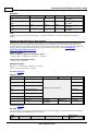
Connection Timeout
This parameter specifies the time that the driver will wait for a connection to be made with a device. Depending
on network load, the connect time may vary with each connection attempt. The valid range is 1 to 30 seconds.
The default setting is 3 seconds.
Request Timeout
This parameter specifies the time that the driver will wait on a response from the device before giving up and
going on to the next request. Longer timeouts only affect performance if a device is not responding. The valid
range is 100 to 30000 milliseconds. The default setting is 2000 milliseconds.
Retry Attempts
This parameter specifies the number of times that the driver will retry a message before giving up and going on
to the next message. The valid range is 1 to 10. The default setting is 2.
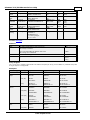
Device IDs
Up to 1024 devices may be defined on a given channel. The device ID is formatted as YYY.YYY.YYY.YYY, where
YYY designates the device's IP address. Each YYY byte should be in the range of 0 to 255. If the device supports
host name resolution, the device ID may also be specified as a standard UNC/DNS name.
Note:
For NetLink users, NetLink communication parameters (such as IP Address, Subnet Mask, and Baud Rate) can be
configured using the NetLink Configuration utility. This application is located in the server's Utilities subdirectory and can be launched using the Start menu shortcut.
www. kepware.com
Siemens TCP/IP Ethernet Driver Help
7
Communications Parameters
Descriptions of the parameters are as follows:
l
Port Number: This parameter specifies the port number that the remote CP is configured to use. The
default setting for IE TCP/IP is 102 (TSAP). The default setting for NetLink is 1099.
Note:
It is recommended that the default port be used for most applications, where the OPC server and the PLC
exist on the same network. For an application that will be using the Internet through firewalls and
advanced routers, the port number can be changed to allow these operations to occur. In most cases,
however, the PLC will only accept a connection on port 102/1099 and may require router forwarding.
l
MPI ID: This parameter is for NetLink only, and is configured for the port in which the NetLink adapter is
connected. It does not apply to models utilizing the IE TCP/IP CPs (such as S7-300 and S7-400). A
maximum of two connections or devices via TCP are possible when using the NetLink adapter.
S7 Communications Parameters
S7-200 Communications Parameters
There are two ways the Siemens TCP/IP Ethernet Driver can communicate to the S7-200 device on an Ethernet
network.
l
l
PG connection (such as, a connection utilized by Micro/WIN). One connection is available.
Configured connection (such as, a connection configured in Micro/WIN via the Ethernet Wizard). Eight
connections are available.
Note:
Configured connections are recommended because they free the PG port for Micro/WIN and also provide
flexibility to make multiple concurrent connections.
Local TSAP
www. kepware.com
Siemens TCP/IP Ethernet Driver Help
8
Link Type
TSAP Value (hex)
PG
4B57 ('KW')
Configured
A remote (client) TSAP configured in Micro/WIN's Ethernet wizard.
If Micro/WIN remote TSAP=xx.yy*, set local TSAP to xxyy.
Remote TSAP
Link Type
TSAP Value (hex)
PG
4B57 ('KW')
Configured
A local (server) TSAP configured in Micro/WIN's Ethernet wizard.
If Micro/WIN remote TSAP=xx.yy*, set local TSAP to xxyy.
*TSAP as displayed in Micro/WIN's Ethernet Wizard. When accessed from V memory, the value may be in decimal
form. For example, if TSAP is 10.00, the V memory value will be 1000 hex or 4096 decimal. The values entered
for Local TSAP must be in hexadecimal notation; in this example, the value 1000 would be entered.
General Rule From the Perspective of the OPC Server
Local TSAP==Micro/WIN remote TSAP
Remote TSAP==Micro/WIN local TSAP
For information on using the CP243-1 module, refer to How to Configure S7-200 Connections in
Micro/WIN.
S7-300/400/1200/1500 Communications Parameters
This setting does not apply to models utilizing the NetLink adapter (NetLink: S7-300 and NetLink: S7-400).
Link Settings
The communication link refers to the connection between the Siemens TCP/IP Ethernet Driver and the CP.
Type
The type of link chosen determines the number of simultaneous requests allowed. The greater the number of
simultaneous requests, the greater the data throughput. Each device connection is allowed one outstanding
request. To achieve multiple simultaneous requests, multiple connections must be configured. This is achieved
by defining the device multiple times in the OPC server (identical device properties). The devices can be defined
within the same channel or under separate channels. For more information, refer to Optimizing Siemens
TCP/IP Ethernet Communication.
Channel.Device=1 CP connection
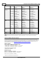
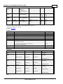
There are three types of links: PC (applications), OP (operator panel), and PG (programming device). OP and PG
are usually reserved but can be used if all PC connections are taken.
Type
S7-300 CPU 314, 315
S7-400 CPU 412, 413
S7-400 CPU 414
S7-400 CPU 416
PC
2
14
30
62
OP
1
1
1
1
PG
1
1
1
1
Default Number Simultaneous Requests
Example:
Given an S7-400 CPU 412, 14 simultaneous requests can be achieved by defining 14 identical devices in the OPC
server with all configured for Link Type PC. In addition to the PC connections, two more devices can be configured
for Link Type OP and PG. This provides 16 connections overall.
Caution: Connection resources are shared amongst applications communicating with the CP. If another
application such as STEP 7 is configured to use Industrial Ethernet over TCP/IP, at least one PG/PC connection
must be left open for that application to use.
Note:
For information on increasing the number of PG, OP and PC type connections, refer to How to Configure S7300/400 Connections in STEP 7.
CPU Settings
The following settings must match the values entered in STEP 7's HW configuration program.
Rack
www. kepware.com
Siemens TCP/IP Ethernet Driver Help
9
This parameter specifies the number of the rack in which the CPU of interest resides. For information on how to
read/write the rack number using an internal tag, refer to Internal Tags.
CPU Slot
This parameter specifies the number of the slot in which the CPU of interest resides. For information on how to
read/write the slot number using an internal tag, refer to Internal Tags.
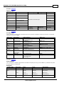
Addressing Options
This dialog is used to set the byte order for 16-bit and 32-bit values. Options include Big Endian (S7 Default)
or Little Endian.
Note:
Big Endian uses bytes ordered from highest to lowest. Little Endian uses bytes ordered from lowest to highest.
The bit order is never changed with either of these methods.
Big Endian
DWord 1
- - - - - - - - 1- 1- 1- 1- 1- 1- - - 2- 2- 2- 2- 1- 1- 1- 1- 3- 3- 2- 2- 2- 2- 2- 27 6 5 4 3 2 1 0 5 4 3 2 1 0 9 8 3 2 1 0 9 8 7 6 1 0 9 8 7 6 5 4
Word 1
Word 3
- - - - - - - - 1- 1- 1- 1- 1- 1- - - 7 6 5 4 3 2 1 0 1- 1- 1- 1- 1- 1- 9 8
7 6 5 4 3 2 1 0 5 4 3 2 1 0 9 8
5 4 3 2 1 0
Byte 1
Byte 2
Byte 3
Byte 4
- - - - - - - - 7 6 5 4 3 2 - - 7 6 5 4 3 2 1 0 7 6 5 4 3 2 1 0
7 6 5 4 3 2 1 0
1 0
Bits
1. The bit range for DWord 1 is 31-0.
2. The bit range for Word 1 and Word 3 is 15-0.
www. kepware.com
Siemens TCP/IP Ethernet Driver Help
10
3. The bit range for Byte 1, Byte 2, Byte 3, and Byte 4 is 7-0.
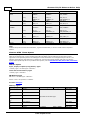
Little Endian
DWord 1
3- 3- 2- 2- 2- 2- 2- 2- 2- 2- 2- 2- 1- 1- 1- 1- 1- 1- 1- 1- 1- 1- - - - - - - - - - 1 0 9 8 7 6 5 4 3 2 1 0 9 8 7 6 5 4 3 2 1 0 9 8 7 6 5 4 3 2 1 0
Word 3
Word 1
1- 1- 1- 1- 1- 1- 9 8 7 6 5 4 3 2 1 0 1- 1- 1- 1- 1- 1- - - - - - - - - - 5 4 3 2 1 0
5 4 3 2 1 0 9 8 7 6 5 4 3 2 1 0
Byte 4
Byte 3
Byte 2
7 6 5 4 3 2 1 0 7 6 5 4 3 2 1 0 7 6 5 4 3 2
Byte 1
- - - - - - - - - 1 0 7 6 5 4 3 2 1 0
Bits
1. The bit range for DWord 1 is 31-0.
2. The bit range for Word 3 and Word 1 is 15-0.
3. The bit range for Byte 4, Byte 3, Byte 2, and Byte 1 is 7-0.
Tag Import
The Tag Import dialog specifies the parameters needed for Automatic Tag Database Generation from a Siemens
STEP 7 project. Automatic Tag Database Generation is supported for Siemens S7-300 and S7-400 devices only.
To generate the tags that have been configured to be imported, open the Database Creation tab located in
Device Properties and then select Auto Create.
Note:
Tag import for the Siemens S7-300 and S7-400 devices have been qualified for use with projects created from
Siemens Simatic STEP 7 versions 5.3, 5.4, and 5.5.
Important:
Tag import for the Siemens TCP/IP Ethernet Driver supports tag names and comments in the native character set
as specified by the Windows code page in the Siemens STEP 7 project's language file. A missing, altered,
corrupt, or incorrect Siemens STEP 7 language file may cause tag names and comments to import incorrectly.
Utilizing the STEP 7 language-neutral option (which allows text to be entered in a different character set than
what is used in the STEP 7 language file) may also cause tag names and comments to import incorrectly. The
STEP 7 language file can be located in the Global sub-directory of the STEP 7 project root.
Note:
Automatic tag generation may result in the display of incorrect characters if the necessary language packs are
not installed on the system.
www. kepware.com
Siemens TCP/IP Ethernet Driver Help
Descriptions of the parameters are as follows:
l
l
STEP 7 Project File (*.S7P): Select the ellipsis button to browse for and select the desired STEP 7
project file (*.S7P) from which tags will be imported. To clear the configured STEP 7 project, click the X
button.
Program Path: After specifying the STEP 7 project's *.S7P file, use this drop-down menu to select the
actual PLC program within the project for which tags will be generated.
www. kepware.com
11
Siemens TCP/IP Ethernet Driver Help
12
Cable Diagrams
www. kepware.com
Siemens TCP/IP Ethernet Driver Help
13
How To Configure S7-200 Connections in Micro/WIN
Configured connections are accomplished through the Ethernet wizard in Micro/WIN. The following instructions
illustrate each step in the Ethernet wizard and also describe any precautions that should be taken. Follow these
instructions closely to use configured connections with the Siemens TCP/IP Ethernet Driver correctly.
Note:
The Micro/WIN software may require an upgrade before the Ethernet wizard is made available.
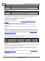
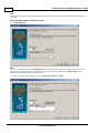
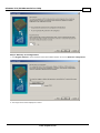
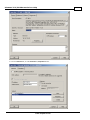
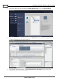
Step 1: Launching the Ethernet Wizard
1. In the Micro/WIN main menu, click Tools | Ethernet Wizard.
2. Then, click Next.
3. Click Yes to proceed.
www. kepware.com
Siemens TCP/IP Ethernet Driver Help
14
Note:
The program must be compiled before the Ethernet wizard can execute. Correct any errors in the program before
continuing.
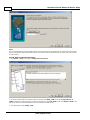
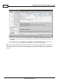
Step 2: Setting CP243-1 Module Position
1. Click Read Modules.
Note:
While it is recommended that the Read Modules function be used, this does require that the PLC be connected to
the PC either serially or by Ethernet. In either case, the communications parameters for Micro/WIN must be
properly set for the Read Modules operation to occur.
2. To view the results of Read Modules, select the Ethernet module. Click Next.
www. kepware.com
Siemens TCP/IP Ethernet Driver Help
15
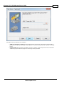
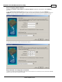
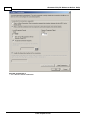
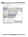
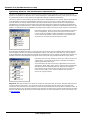
Step 3: Assigning Module Address
1. Enter the IP Address, Subnet Mask and Gateway Address if applicable. Alternatively, enable BOOTP if
applicable.
2. Select Auto Detect Communications to allow the module to automatically select either 10BaseT or
100BaseT. In rare cases where there may be a cable issue that does not allow the module to operate properly at
100BaseT, force the module to use 10BaseT. This will increase the modules' tolerance to a bad Ethernet line.
3. The image shown below contains demonstration values.
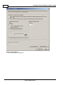
Step 4: Number of Configured Connections
1. Enter the number of desired available connections for this device. If 0 is entered, the only connection available
will be the PG connection used by Micro/WIN.
www. kepware.com
Siemens TCP/IP Ethernet Driver Help
16
Note:
The number of connections selected determines how many simultaneous connections the PLC can support. When
intending to have only one OPC server talking to the PLC, set up only one connection. This will ensure the best
performance for the OPC server. When intending to have more than one active connection to the PLC, use multiple
connections. Keep in mind, however, that the performance of the module will be impacted as each connection is
used.
2. The image shown below contains 4 connections.
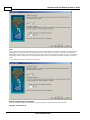
Step 5: Configuring Connections
Each connection is configured individually. For this example, 4 connections have been selected.
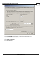
Step 5a: Connection 0
www. kepware.com
Siemens TCP/IP Ethernet Driver Help
17
There are two types of connections, client and server. In a client connection, the device is a client and makes
request with servers (other devices). In a server connection, the device is a server and handles requests from
clients (such as the OPC server and other devices). The latter is required for communications with the Siemens
TCP/IP Ethernet Driver.
1. Select This is a Server Connection.
2. From this standpoint, the CP243-1 is considered the Server (local) and the OPC Server Channel. The
device is considered the Client (Remote).
3. Enter a Remote TSAP or accept the default. This will be the Local TSAP in the OPC Server.
4. Optional: Accept all connection requests or limit to a particular remote machine. It is recommended that
Accept all connection requests be selected. If concerned about device security (or if intending to access this
device over the Internet) select a specific IP address. Users must ensure that the OPC server is running on a PC
that has a known and fixed IP address.
5. Select Enable the Keep Alive.
6. Click Next Connection.
www. kepware.com
Siemens TCP/IP Ethernet Driver Help
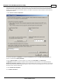
18
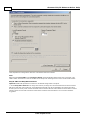
Step 5b: Connection 1
1. Select This is a Server Connection.
www. kepware.com
Siemens TCP/IP Ethernet Driver Help
2. Notice the Local TSAP automatically incremented to 11.00.
3. Enter a Remote TSAP or accept the default. This will be the Local TSAP in the OPC Server.
4. Optional: Accept all connection requests.
5. Select Enable the Keep Alive.
6. Click Next Connection.
www. kepware.com
19
Siemens TCP/IP Ethernet Driver Help
20
Step 5c: Connection 2
1. Select This is a Server Connection.
www. kepware.com
Siemens TCP/IP Ethernet Driver Help
2. Notice the Local TSAP automatically incremented to 12.00.
3. Enter a Remote TSAP or accept the default. This will be the Local TSAP in the OPC Server.
4. Optional: Accept all connection requests.
5. Select Enable the Keep Alive.
6. Click Next Connection.
www. kepware.com
21
Siemens TCP/IP Ethernet Driver Help
22
Step 5d: Connection 3
1. Select This is a Server Connection....
www. kepware.com
Siemens TCP/IP Ethernet Driver Help
2. Notice the Local TSAP automatically incremented to 13.00.
3. Enter a Remote TSAP or accept the default. This will be the Local TSAP in the OPC server.
4. Optional: Accept all connection requests.
5. Select Enable the Keep Alive.
6. Click Next Connection.
www. kepware.com
23
Siemens TCP/IP Ethernet Driver Help
24
That completes the configuration of the four connections that were selected.
Note:
Notice that the Local TSAP in the Connection dialog was automatically advanced for each connection. This
TSAP number will need to be used in the OPC server setup when defining a device as the remote TSAP number.
Step 6: CRC and Keep Alive Interval
Optional: Enable CRC protection to monitor for accidental configuration corruption.
1. Set the Keep Alive Interval. The longer the interval, the longer the connection between the device and the
OPC server will exist during idle time. A long Keep Alive Interval may not be desirable if connections are being
shared (nonconcurrent). Each remote client will need to wait this amount of time before it will be able to connect
with the device once the last connected remote client is finished communications. The 30 second default is
suggested.
www. kepware.com
Siemens TCP/IP Ethernet Driver Help
25
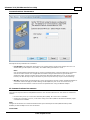
Step 7: Memory for Configuration
1. Click Suggest Address to let the wizard find the best available location to store the Ethernet configuration.
2. The image shown below displays the results.
www. kepware.com
Siemens TCP/IP Ethernet Driver Help
26
Note:
It is recommended that the Micro/WIN software pick this location for the application. If a CRC was not generated
for the configuration data, please take steps to ensure that no other aspect of the PLC program will overwrite this
area of memory.
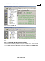
Step 8: Ethernet Wizard Summary
1. Click Finish or Prev to modify the Configured Connections.
2. To review what the Ethernet wizard produced, double-click ETH0_CTRL under the Program Block. All
TSAPs configured are listed for future reference. Remember, the Local TSAP below is the Remote TSAP in the
OPC server and the remote TSAP below is the Local TSAP in the OPC server.
3. The image below shows ETH0_CTRL.
www. kepware.com
Siemens TCP/IP Ethernet Driver Help
27
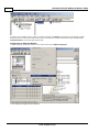
4. The image below shows ETH0_CFG.
5. Now that the results of the Ethernet wizard have been confirmed, a connection can be made using the OPC
server.
How To Configure S7-300/400 Connections in STEP 7
to configure the S7-300/400 for communications with the Siemens TCP/IP Ethernet Driver, both the CPU and the
Ethernet module will need to be configured as well. To do so, follow the directions below.
1. From the Simatic Manager, launch HW Config by double-clicking Hardware under the SIMATIC Station.
www. kepware.com
Siemens TCP/IP Ethernet Driver Help
28
2. If this is a new Simatic project, add the necessary modules to the Rack in HW Config. For the Siemens TCP/IP
Ethernet Driver to communicate with the CPU, there will need to be at least one Ethernet module capable of S7
Communications. This may be built into the CPU.
Configuring an Ethernet Module
1. Right-click on the particular module in the rack and then select Object Properties.
2. The dialog should appear as shown below.
www. kepware.com
Siemens TCP/IP Ethernet Driver Help
3. From the General tab, click the Interface | Properties button.
www. kepware.com
29
Siemens TCP/IP Ethernet Driver Help
30
4. Specify the IP and Subnet Mask for this module.
5. To network this module, click New under Subnet. Next, select the network created and the click OK.
6. Return to the HW Config main window.
Configuring Connections
1. Right-click on the CPU module in the rack and select Object Properties.
2. The dialog should appear as shown below.
www. kepware.com
Siemens TCP/IP Ethernet Driver Help
31
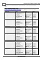
3. Configure the desired number of PG/OP and PC (S7 Communication) connections.
Type
Description
PG Communication
Used for program loading, diagnostics
OP Communication
Used for operator control and monitoring
S7 Standard
Communication
Communication connections not configured, MPI communications with PUT/GET
function blocks
S7 Communication (PC)
Configured connections, data communications
Note:
The maximum number of PC connections for the CPU equals the Maximum Number of Connection Resources
minus the S7 Standard Communication resources minus the OP Communication resources minus the PG
Communication resources. Note that the Maximum Number of Connection Resources is based on the
CPU/version/firmware.
In the example shown above, there are six S7 communication (PC) connections available (12-4-1-1=6). Likewise,
the number of PG and OP connections can be increased using the same concept.
If the Device returned protocol [Class=0x83, Code=0x04] error is encountered, increase the number of S7
Standard Communication connections, thereby decreasing the number of S7 Communication connections.
4. After the connections have been configured, click OK. Next, in the main HW Config window click Station |
Save and Compile.
5. Click PLC | Download to commit to the changes.
How To Configure S7-1200 Connections with the Totally Integrated Automation
(TIA) Portal
to configure the S7-1200 for communications with the Siemens TCP/IP Ethernet Driver, an online connection is
required between the programming device and the target system. Users may have to configure the programming
device to talk to the target system. For more information, follow the instructions below.
www. kepware.com
32
Siemens TCP/IP Ethernet Driver Help
Note:
For new Simatic projects, refer to the PLC's documentation for information on the default IP address settings.
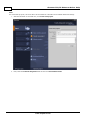
1. Start the TIA Portal. In the Portal View, click Create new project.
2. Next, select the Online & Diagnostics tab and then click Accessible Devices.
www. kepware.com
Siemens TCP/IP Ethernet Driver Help
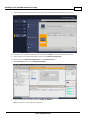
3. Select the appropriate PG/PC interface. This will prompt the TIA to scan the network for the device.
4. Once the scan is complete, select the device and then click Show. This will invoke the Project View.
5. In the project tree, locate the IP address and then open Online & Diagnostics.
6. Next, double-click Online & Diagnostics to invoke Online Access.
7. Select Functions and then click Assign IP Address.
8. Enter the communication settings and click Assign IP Address.
Note: The device is now ready to be configured.
www. kepware.com
33
34
Siemens TCP/IP Ethernet Driver Help
9. Return to the Portal View and then select the Device & Networks tab. Then, click Add new device.
10. Next, select the device's configuration and then click Add device. This will invoke the Project View, where
the device's hardware can be further configured.
11. Once finished, view the project tree. Locate Program Blocks and PLC Tags and then configure the
addresses that will be used in the PLC project.
www. kepware.com
Siemens TCP/IP Ethernet Driver Help
Note: The device is now configured and can be placed in Run Mode for communications.
How To Configure S7-1500 Connections
The S7-1500 controller has an embedded Ethernet port that supports S7 communications over the Ethernet
protocol. It must be configured to allow access from the server, however. For more information, refer to the
instructions below.
1. To start, open the PLC project in the S7 AI Portal software.
2. Next, open PLC Properties.
3. In the General tab, select Protection. Then, ensure that Full access (no protection) is enabled.
Note: At this time, the Siemens TCP/IP Ethernet Driver does not support the use of a password.
4. Next, check Permit access with PUT/GET communication from remote partner. Then, save the
settings.
www. kepware.com
35
36
Siemens TCP/IP Ethernet Driver Help
5. In the server, create a new channel. In Device Driver, select Siemens TCP/IP Ethernet Driver from
the drop-down list. Continue through the channel wizard, specifying channel properties as needed. Then,
click Finish.
6. Next, create a new device. In Model, select S7-1500 from the Device Model drop-down list. Continue
through the device wizard, specifying device properties as needed. Then, click Finish.
Note: The controller Protection settings are directly related to the device returning protocol error [Class=0x81,
Code=0x04]. If this error occurs, the controller's memory (such as the Simatic memory card) may need to be
reset. Once the controller's memory is reset, downloading the S7 project to the controller should not prompt for a
password.
www. kepware.com
Siemens TCP/IP Ethernet Driver Help
37
Optimizing Siemens TCP/IP Ethernet Communications
The Siemens TCP/IP Ethernet Driver was designed to provide the best performance with the least amount of
impact on the system's overall performance. While the Siemens TCP/IP Ethernet Driver is fast, there are a couple
of guidelines that can be used to optimize the application and gain maximum performance.
This server refers to communications protocols like Siemens TCP/IP Ethernet as a channel. Each channel defined
in the application represents a separate path of execution in the server. Once a channel has been defined, a
series of devices can then be defined under that channel. Each of these devices represents a single Siemens
TCP/IP Ethernet controller from which data will be collected. Although this approach to defining the application
provides a high level of performance, it does not take full advantage of the Siemens TCP/IP Ethernet Driver or the
network. An example of how the application may appear when configured using a single channel is shown below.
Each device appears under a single Siemens TCP/IP Ethernet channel.
In this configuration, the driver must move from one device to the
next as quickly as possible to gather information at an effective rate.
As more devices are added or more information is requested from a
single device, the overall update rate begins to suffer.
If the Siemens TCP/IP Ethernet Driver could only define one channel, then the example above would be the only
option available; however, the Siemens TCP/IP Ethernet Driver can define up to 256 channels. Using multiple
channels distributes the data collection workload by simultaneously issuing multiple requests to the network. An
example of how the same application may appear when configured using multiple channels is shown below.
Each device has now been defined under its own channel. In this new
configuration, a single path of execution is dedicated to the task of
gathering data from each device.
The performance will improve even if the application has more than
256 devices. While 256 or fewer devices may be ideal, the application
will still benefit from additional channels. Although spreading the
device load across all channels will cause the server to move from
device to device again, it can now do so with far less devices to
process on a single channel.
Important: Although the OPC server limits the number of channels to 256, the device ultimately determines the
number of allowed connections. This constraint comes from the fact that some devices cannot support 256
connections. For these devices, the maximum number of channels defined should equal the maximum number of
connections allowed. For devices that support more than 256 connections, the maximum 256 channels should be
defined, with devices spread evenly over these 256 channels. For more information on device connections, refer
to Link Settings.
www. kepware.com
Siemens TCP/IP Ethernet Driver Help
38
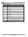
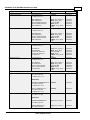
Data Types Description
Data Type
Description
Boolean
Single bit
Byte
Unsigned 8-bit value
Char
Signed 8-bit value
Word
Unsigned 16-bit value
bit 0 is the low bit
bit 15 is the high bit
Short
Signed 16-bit value
bit 0 is the low bit
bit 14 is the high bit
bit 15 is the sign bit
BCD
Two byte packed BCD
DWord
Unsigned 32-bit value
Value range is 0-9999. Behavior is undefined for values beyond this range
bit 0 is the low bit
bit 31 is the high bit
Long
Signed 32-bit value
bit 0 is the low bit
bit 30 is the high bit
bit 31 is the sign bit
LBCD
Four byte packed BCD
Float
32-bit floating point value
Value range is 0-99999999. Behavior is undefined for values beyond this range
The driver interprets two consecutive registers as a floating-point value by making the
second register the high word and the first register the low word.
Date
64-bit floating-point value
String
Null-terminated ASCII string*
*The Data Block subtype, String, is a NULL padded ASCII string.
www. kepware.com
Siemens TCP/IP Ethernet Driver Help
39
Address Descriptions
Address specifications vary depending on the model in use. Select a link from the following list to obtain
information for the model of interest.
S7-200 Address Descriptions
S7-300 Address Descriptions
S7-400 Address Descriptions
S7-1200 Address Descriptions
S7-1500 Address Descriptions
NetLink: S7-300 Address Descriptions
NetLink: S7-400 Address Descriptions
Internal Tags
S7-200 Address Descriptions
The default data types for dynamically defined tags are shown in bold.
Address Type
Range
Discrete Inputs (IEC)
I0.b-I65535.b
Boolean
.b is Bit Number 0-7
Read/Write
IB0-IB65535
IW0-IW65534
ID0-ID65532
Read/Write
Read/Write
Read/Write
Discrete Inputs (SIMATIC)
Type
Byte, Char, String**
Word, Short, BCD
DWord, Long, LBCD,
Float
Access
E0.b-E65535.b
Boolean
.b is Bit Number 0-7
Read/Write
EB0-EB65535**
EW0-EW65534
ED0-ED65532
Read/Write
Read/Write
Read/Write
Byte, Char, String**
Word, Short, BCD
DWord, Long, LBCD,
Float
Note: I and E access the same memory area.
Discrete Outputs (IEC)
Discrete Outputs (SIMATIC)
Q0.b-Q65535.b
Boolean
.b is Bit Number 0-7
Read/Write
QB0-QB65535
QW0-QW65534
QD0-QD65532
Read/Write
Read/Write
Read/Write
Byte, Char, String**
Word, Short, BCD
DWord, Long, LBCD,
Float
A0.b-A65535.b
Boolean
.b is Bit Number 0-7
Read/Write
AB0-AB65535
AW0-AW65534
AD0-AD65532
Byte, Char, String**
Word, Short, BCD
DWord, Long, LBCD,
Float
Read/Write
Read/Write
Read/Write
Analog Inputs (IEC)
AI0-AI65534***
AIW0-AIW65534
Word, Short
Read Only
Analog Inputs (SIMATIC)
AE0-AE65534***
AEW0-AEW65534
Word, Short
Read Only
Analog Outputs (IEC)
AQ0-AQ65534***
AQW0-AQW65534
Word, Short
Read/Write
Analog Outputs (SIMATIC)
AA0-AA65534***
AAW0-AAW65534
Word, Short
Read/Write
Note: Q and A access the same memory area.
Note: AI and AE access the same memory
area.
Note: AQ and AA access the same memory area.
Internal Memory M0.b-M65535.b
Boolean
.b is Bit Number 0-7
www. kepware.com
Read/Write
Siemens TCP/IP Ethernet Driver Help
40
MB0-MB65535
MW0-MW65534
MD0-MD65532
Special Memory
(Bytes 0-29 are Read Only)
Sequence Control Relay (SCR)
Variable Memory
Byte, Char, String**
Word, Short, BCD
DWord, Long, LBCD,
Float
Read/Write
Read/Write
Read/Write
SM0.b-SM65535.b
Boolean
.b is Bit Number 0-7
Read/Write
SMB0-SMB65535
SMW0-SMW65534
SMD0-SMD65532
Read/Write
Read/Write
Read/Write
Byte, Char, String**
Word, Short, BCD
DWord, Long, LBCD,
Float
S0.b-S65535.b
Boolean
.b is Bit Number 0-7
Read/Write
SB0-SB65535
SW0-SW65534
SD0-SD65532
Read/Write
Read/Write
Read/Write
Byte, Char, String**
Word, Short, BCD
DWord, Long, LBCD,
Float
V0.b-V65535.b
Boolean
.b is Bit Number 0-7
Read/Write
VB0-VB65535
VW0-VW65535
VD0-VD65535
Byte, Char, String**
Word, Short, BCD
DWord, Long, LBCD,
Float
Read/Write
Read/Write
Read/Write
Timer Current Values
T0-T65535*
DWord, Long
Read/Write
Timer Status Bit
T0-T65535*
Boolean
Read Only
Counter Current Values (IEC)
C0-C65535*
Word, Short
Read/Write
Counter Status Bit (IEC)
C0-C65535*
Boolean
Read Only
Counter Current Values (SIMATIC)
Z0-Z65535*
Word, Short
Read/Write
Counter Status Bit (SIMATIC)
Z0-Z65535*
Boolean
Read Only
HC0-HC65535*
DWord, Long
Read Only
Note: C and Z access the same memory area.
High-Speed Counter
*These memory types/subtypes do not support arrays.
**Byte memory types (MB) support strings. The syntax for strings is <address>.<length> where 0 < length <=
212.
***For Analog Inputs and Outputs, the address must be even (AI0, AI2, AI4, and so forth).
Notes:
1. All offsets for memory types I, Q, M, S, and SM represent a byte starting location within the specified
memory type.
2. Use caution when modifying Word, Short, DWord, and Long types. For I, Q, and F, each address starts at
a byte offset within the device. Therefore, Words MW0 and MW1 overlap at byte 1. Writing to MW0 will
also modify the value held in MW1. Similarly, DWord, and Long types can also overlap. It is recommended
that these memory types be used so that overlapping does not occur. For example, DWord MD0, MD4,
MD8, and so on can be used to prevent overlapping bytes.
Arrays
All memory types/subtypes with the exception of those marked with an asterisk support arrays. The valid syntax
for declaring an array is as follows:
<address>[rows][cols]
<address>.rows.cols
<address>,rows,cols
<address>_rows_cols
Note:
If no rows are specified, a row count of 1 is assumed.
For Word, Short, and BCD arrays, the base address + (rows * cols * 2) cannot exceed 65536. Keep in mind that
the elements of the array are words, located on a word boundary. For example, IW0[4] would return IW0, IW2,
IW4, and IW6.
www. kepware.com
Siemens TCP/IP Ethernet Driver Help
41
For Float, DWord, Long, and Long BCD arrays, the base address + (rows * cols * 4) cannot exceed 65536. Keep
in mind that the elements of the array are DWord, located on a DWord boundary. For example, ID0[4] will return
ID0, ID4, ID8, and ID12.
For all arrays, the total number of bytes being requested cannot exceed the internal block size of 218 bytes.
S7-300 Address Descriptions
Standard Support
S7-300/400/1200/1500 Item Syntax
Internal Tags
Third-Party Support
For users familiar with the following applications, limited addressing support is available.
Applicom Direct-Link Item Syntax
INAT OPC-Server TCPIPH1 Item Syntax
Siemens Simatic Net Item Syntax
Siemens STEP 7 Item Syntax
Softing S7/S5 OPC Server Item Syntax
Legacy Support
Legacy S7-300/400 Item Syntax
Note:
All brand and product names are trademarks, registered trademarks, or service marks of their respective
holders.
S7-400 Address Descriptions
Standard Support
S7-300/400/1200/1500 Item Syntax
Internal Tags
Third-Party Support
For users familiar with the following applications, limited addressing support is available.
Applicom Direct-Link Item Syntax
INAT OPC-Server TCPIPH1 Item Syntax
Siemens Simatic Net Item Syntax
Siemens STEP 7 Item Syntax
Softing S7/S5 OPC Server Item Syntax
Legacy Support
Legacy S7-300/400 Item Syntax
Note:
All brand and product names are trademarks, registered trademarks, or service marks of their respective
holders.
S7-1200 Address Descriptions
Standard Support
S7-300/400/1200/1500 Item Syntax
Internal Tags
Third-Party Support
For users familiar with the following applications, limited addressing support is available.
Applicom Direct-Link Item Syntax
INAT OPC-Server TCPIPH1 Item Syntax
Siemens Simatic Net Item Syntax
Siemens STEP 7 Item Syntax
Softing S7/S5 OPC Server Item Syntax
Legacy Support
Legacy S7-300/400 Item Syntax
www. kepware.com
Siemens TCP/IP Ethernet Driver Help
42
Note:
All brand and product names are trademarks, registered trademarks, or service marks of their respective
holders.
S7-1500 Address Descriptions
Standard Support
S7-300/400/1200/1500 Item Syntax
Internal Tags
Third-Party Support
For users familiar with the following applications, limited addressing support is available.
Applicom Direct-Link Item Syntax
INAT OPC-Server TCPIPH1 Item Syntax
Siemens Simatic Net Item Syntax
Siemens STEP 7 Item Syntax
Softing S7/S5 OPC Server Item Syntax
Legacy Support
Legacy S7-300/400 Item Syntax
Note:
All brand and product names are trademarks, registered trademarks, or service marks of their respective
holders.
NetLink: S7-300 Address Descriptions
Standard Support
S7-300/400/1200/1500 Item Syntax
Third-Party Support
For users familiar with the following applications, limited addressing support is available.
Applicom Direct-Link Item Syntax
INAT OPC-Server TCPIPH1 Item Syntax
Siemens Simatic Net Item Syntax
Siemens STEP 7 Item Syntax
Softing S7/S5 OPC Server Item Syntax
Legacy Support
Legacy S7-300/400 Item Syntax
Note:
All brand and product names are trademarks, registered trademarks, or service marks of their respective holders
NetLink: S7-400 Address Descriptions
Standard Support
S7-300/400/1200/1500 Item Syntax
Third-Party Support
For users familiar with the following applications, limited addressing support is available.
Applicom Direct-Link Item Syntax
INAT OPC-Server TCPIPH1 Item Syntax
Siemens Simatic Net Item Syntax
Siemens STEP 7 Item Syntax
Softing S7/S5 OPC Server Item Syntax
Legacy Support
Legacy S7-300/400 Item Syntax
Note:
All brand and product names are trademarks, registered trademarks, or service marks of their respective holders
www. kepware.com
Siemens TCP/IP Ethernet Driver Help
43
Internal Tags
Although the following internal tags are not visible in the server configuration, they can be browsed by the OPC
client. They can be found under the <Channel Name>.<Device Name>._InternalTags group. If the OPC client
does not support browsing, or if a non-OPC client is being used, the tags can be created dynamically and
statically by using the addresses given below.
Note:
The tags listed in the following table are valid for the S7-300, S7-400, S7-1200, and S7-1500 device models.
The default data types are shown in bold.
Device Address
Description
Range
Data Type
Access
_RACK
Number of the rack in which the CPU of
interest resides.
0-7
Byte, Short
Read/Write
2-31
Byte, Short
Read/Write
On changing this device property, the
connection with the CPU is re-established.
_SLOT
Number of the slot in which the CPU of
interest resides.
On changing this device property, the
connection with the CPU is re-established.
Standard S7-300/400/1200/1500 Item Syntax
Address Syntax
Input, Output, Peripheral, Flag Memory Types
<memory type><S7 data type><address>
<memory type><S7 data type><address><.bit>
<memory type><S7 data type><address><.string length>*
<memory type><S7 data type><address><[row][>col]>
Timer and Counter Memory Types
<memory type><address>
DB Memory Type
DB<num>,<S7
DB<num>,<S7
DB<num>,<S7
DB<num>,<S7
data type><address>
data type><address><.bit>
data type><address><.string length>*
data type><address><[row][col]>
where <num> ranges from 1 to 65535.
*Applies to S7 data types that support string. String length can vary from 0<n<= 212, with the exception of S7
data type string (which can vary from 0<n<= 210).
See Also:
Examples and String Support.
Memory Types
Memory Type
Description
I
E
Inputs
Address Range
Data Type
Access
Read/Write
Q
A
Outputs
Read/Write
PI
PE
Peripheral Inputs
PQ
PA
Peripheral Outputs
Read/Write
M
F
Flag Memory
Read/Write
DB
Data Blocks
T
Timers
T0-T65535
DWord, Long
Read/Write
C
Z
Counters
C0-C65535
Z0-Z65535
Word, Short
Read/Write
Read Only
Dependent on S7 Data Type
Read/Write
www. kepware.com
Siemens TCP/IP Ethernet Driver Help
44
See Also: Examples
S7 Data Types
The S7 data type is used to coerce the data type for a tag. It does not apply to Timers and Counters. The default
data types are shown in bold.
S7
Data
Type
B
Byte
Data
Type
Description
Address Range
Unsigned Byte
B0-B65535
BYTE0BYTE65535
Byte,
Char
B0.b-B65535.b
BYTE0.bBYTE65535.b
.b is Bit Number
0-7
Boolean
String*
B0.n-B65535.n
BYTE0.nBYTE65535.n
.n is string
length.
0 < n <= 212.
C
Char
Signed Byte
C0-C65535
CHAR0CHAR65535
Byte,
Char
C0.b-C65535.b
CHAR0.bCHAR65535.b
.b is Bit Number
0-7
Boolean
String*
C0.n-C65535.n
CHAR0.nCHAR65535.n
.n is string
length.
0<n<= 212.
D
DWORD
Unsigned
Double Word
D0-D65532
DWORD0DWORD65532
D0.b-D65532.b
DWORD0.bDWORD65532.b
.b is Bit Number
0-31
DATE
S7 Date
DWord,
Long,
LBCD,
Float
Boolean
DATE0DATE65534
String
DI0-DI65532
DINT0DINT65532
DWord,
Long,
LBCD,
Float
Stored as WORD in steps of 1 day since January 1, 1990.
Displayed as string format "yyyy-mm-dd" with range "1990-01-01"
to "2168-12-31".
Read/Write
DI
DINT
Signed
Double Word
DI0.b-
www. kepware.com
Siemens TCP/IP Ethernet Driver Help
45
DI65532.b
DINT0.bDINT65532.b
.b is Bit Number
0-31
DT
S7 Date_And_Time
Boolean
DT0-DT65528
String,
Date
I0-I65534
INT0-INT65534
Word,
Short,
BCD
Complex data type stored with 8 bytes as follows:
0 year, 1 month, 2 days, 3 hours, 4 minutes, 5 seconds, 6 two most
significant digits of MSEC, 7 (4MSB) two least significant digits of
MSEC, 7 (4LSB) day of week (1=Sunday).
Displayed as string format "m/d/y h:mm:ss <AM/PM>" with range
"1/1/1990 0:00:00 AM" to "12/31/2089 23:59:59 PM".
Displayed as date format
"yyyy-mm-ddThh:mm:ss.hhh" with range "1990-0101T00:00:00.000" to
"2089-12-31T23:59:59.998".
Read Only.
I
INT
Signed Word
I0.b-I65534.b
INT0.bINT65534.b
.b is Bit Number
0-15
Boolean
REAL
IEEE Float
REAL0REAL65532
Float
String
S7 String
STRING0.nSTRING65532.n
.n is string
length.
0<n<= 210.
String
T
TIME
S7 TIME.
T0-T65532
TIME0TIME65532
String
TOD0TOD65532
String
W0-W65534
WORD0WORD65534
Word,
Short,
BCD
Stored as DWORD in steps of milliseconds.
Displayed as string format "+/-ddD_hhH_mmM_ssS_hhhMS" with
range "-24D_20H_31M_23S_648MS" to "24D_20H_31M_23S_
647MS.
Read/Write.
TOD
S7 Time_Of_Day.
Stored as DWORD, representing milliseconds since midnight.
Displayed as string format "h:m:s.mmm" with range "0:0:0.0" to
"23:59:59.999".
Read/Write.
W
Word
Unsigned Word
W0.b-W65534.b
WORD0.bWORD65534.b
.b is Bit Number
0-15
X
Bit
X0.b-X65534.b
.b is Bit Number
www. kepware.com
Boolean
Boolean
Siemens TCP/IP Ethernet Driver Help
46
0-15
*These are raw strings that differ in structure and usage from the STEP 7 string data type.
Note:
Use caution when modifying Word, Short, DWord, and Long type as each address starts at a byte offset within
the device. Therefore, Words MW0 and MW1 overlap at byte 1. Writing to MW0 will also modify the value held in
MW1. Similarly, DWord, and Long types can also overlap. It is recommended that these memory types be used so
that overlapping does not occur. For example, DWord MD0, MD4, MD8, and so on can be used to prevent
overlapping bytes.
See Also: Examples
String Support
Raw Strings
For an address DBx,By.n @ string, string values read and written are stored at byte offset y.
y
y+1
y+2
...
y+n-1
''
''
''
...
''
Raw strings are null terminated. If the maximum string length is 10 and 3 characters are written, the fourth
character is set to NULL, while characters 5-10 are left untouched.
String Support
The string subtype follows the STEP 7 string data type definition. The syntax for the string S7 data type is
STRINGy.n where y is the Byte offset, and n is the maximum string length. If n is not specified, the maximum
string length will be 210 characters. String values read and written are stored at byte offset y+2 in data block x.
The actual string length gets updated with every write based on the string length of the string being written.
y
y+1
y+2
y+3
y+4
...
y+2+n-1
maximum string length (n)
actual string length
''
''
''
...
''
Note:
String strings are NULL padded. If the maximum string length is 10 and 3 characters are written, characters 410 are set to NULL.
Hex Strings
The HEXSTRING subtype is specific to the Siemens TCP/IP Ethernet Driver. The syntax for the HEXSTRING
subtype is HEXSTRINGy.n, where y is the byte offset and n is the length. The n value must be specified in the
range of 1 through 212. String is the only valid data type for a HEXSTRING tag.
The value assigned to a HEXSTRING must be an even number of characters. There is no padding, so the entire
string must be specified. For example, tag HexStr defined as DB1,STRING0.10 uses 10 bytes of storage and has
a display length of 20. To assign a value, the string must be 20 characters long and contain only valid
hexadecimal characters. An example valid hex string for this tag is “56657273696f6E353137”.
Array Support
The [rows][cols] notation is appended to an address to specify an array (such as MW0[2][5]). If no rows are
specified, row count of 1 is assumed. Boolean arrays and string arrays are not supported.
For Word, Short, and BCD arrays, the base address + (rows * cols * 2) cannot exceed 65536. Keep in mind that
the elements of the array are words, located on a word boundary. For example, IW0[4] would return IW0, IW2,
IW4, and IW6.
For Float, DWord, Long, and Long BCD arrays, the base address + (rows * cols * 4) cannot exceed 65536. Keep
in mind that the elements of the array are DWord, located on a DWord boundary. For example, ID0[4] will return
ID0, ID4, ID8, ID12.
For all arrays, the total number of bytes being requested cannot exceed the internal block size of 212 bytes.
Timers
The Siemens TCP/IP Ethernet Driver automatically scales T values based on the Siemens S5 time format. Timer
data is stored as a Word in the PLC but scaled to a DWord in the driver. The value returned will already be scaled
using the appropriate Siemens time base. As a result, the values are always returned as a count of milliseconds.
www. kepware.com
Siemens TCP/IP Ethernet Driver Help
47
When writing to T memory, the Siemens time base will also be applied. To assign a value to a timer in the
controller, write the desired value as a count of milliseconds to the appropriate timer.
Counters
The value returned for C memory will automatically be converted to a BCD value.
Examples
S7 Data Type
Data Type
Input
Flags
Data Blocks
B
Byte
Byte
IB0
IBYTE0
MB0
MBYTE0
DB1,B0
DB1,BYTE0
Boolean
IB0.7
IBYTE0.7
MB0.7
MBYTE0.7
DB1,B0.7
DB1,BYTE0.7
String
IB0.64
IBYTE0.64
MB0.64
MBYTE0.64
DB1,B0.64
DB1,BYTE0.64
Array
IB0[2][5]
IBYTE0[2][5]
MB0[2][5]
MBYTE0[2][5]
DB1,B0[2][5]
DB1,BYTE0[2][5]
Char
IC0
ICHAR0
MC0
MCHAR0
DB1,C0
DB1,CHAR0
Boolean
IC0.7
ICHAR0.7
MC0.7
MCHAR0.7
DB1,C0.7
DB1,CHAR0.7
String
IC0.64
ICHAR0.64
MC0.64
MCHAR0.64
DB1,C0.64
DB1,CHAR0.64
Array
IC0[10]
ICHAR0[10]
MC0[10]
MCHAR0[10]
DB1,C0[10]
DB1,CHAR0[10]
DWord
ID0
IDWORD0
MD0
MDWORD0
DB1,D0
DB1,DWORD0
Boolean
ID0.31
IDWORD0.31
MD0.31
MDWORD0.31
DB1,D0.31
DB1,DWORD0.31
Array
ID0[10]
IDWORD0[10]
MD0[10]
MDWORD0[10]
DB1,D0[10]
DB1,DWORD0[10]
DATE
String
IDATE0
MDATE0
DB1,DATE0
DI
DINT
Long
IDI0
IDINT0
MDI0
MDINT0
DB1,DI0
DB1,DINT0
Boolean
IDI0.31
IDINT0.31
MDI0.31
MDINT0.31
DB1,DI0.31
DB1,DINT0.31
Array
IDI0[4][3]
IDINT0[4][3]
MDI0[4][3]
MDINT0[4][3]
DB1,DI0[4][3]
DB1,DINT0[4][3]
DT
String
Date
IDT0
IDT8
MDT0
MDT8
DB1,DT0
DB1,DT8
I
INT
Short
II0
IINT0
MI0
MINT0
DB1,I0
DB1,INT0
Boolean
II0.15
IINT0.15
MI0.15
MINT0.15
DB1,I0.15
DB1,INT0.15
Array
II0[5][2]
IINT0[5][2]
MI0[5][2]
MINT0[5][2]
DB1,I0[5][2]
DB1,INT0[5][2]
Float
IREAL0
MREAL0
DB1,REAL0
C
Char
D
DWORD
REAL
Array
IREAL0[10]
MREAL0[10]
DB1,REAL0[10]
String
String
ISTRING0.10
MSTRING0.10
DB1,STRING0.10
TOD
String
ITOD0
MTOD0
DB1,TOD0
T
String
IT0
MT0
DB1,T0
www. kepware.com
Siemens TCP/IP Ethernet Driver Help
48
TIME
W
Word
X
ITIME4
MTIME4
DB1,TIME4
Word
IW0
IWORD0
MW0
MWORD0
DB1,W0
DB1,WORD0
Boolean
IW0.15
IWORD0.15
MW0.15
MWORD0.15
DB1,W0.15
DB1,WORD0.15
Array
IW0[10]
IWORD0[10]
MW0[10]
MWORD0[10]
DB1,W0[10]
DB1,WORD0[10]
Boolean
IX0.7
IX0[10]
MX0.7
MX0[10]
DB1,X0.7
DB1,X0[10]
Applicom Direct-Link Item Syntax
The following support for the Applicom Direct-Link OPC server is considered to be limited. Care must be taken
because the data type for a given S7 data type/suffix may differ from the data type for the same S7 data
type/suffix in the specified product. Applicom ASCII strings are not supported by this driver. The following
information is intended to be a guideline for users that are already familiar with and/or prefer the syntax of the
specified product. For preferred item syntax, refer to Standard S7-300/400/1200/1500 Item Syntax.
Address Syntax
Input, Output, Peripheral, Flag Memory Types
<memory type><S7 data type><address>[<Data Type suffix>] [<Byte Switching suffix>]
<memory type><S7 data type><address>[<Data Type suffix>]<_row_col>
Timer and Counter Memory Types
<memory type><address>
DB Memory Type
DB<num>.<S7 data type><address>[<Data Type suffix>][< Byte Switching suffix>]
DB<num>.<S7 data type><address>[<Data Type suffix>]<_row_col>
Where <num> ranges from 1 to 65535.
See Also: Examples
Memory Types
Memory Type
Description
I
E
Inputs
Address Range
Data Type
Access
Read/Write
Q
A
Outputs
Read/Write
PI
PE
Peripheral Inputs
PQ
PA
Peripheral Outputs
Read/Write
M
F
Flag Memory
Read/Write
DB
Data Blocks
T
Timers
T0-T65535
DWord, Long
Read/Write
C
Z
Counters
C0-C65535
Z0-Z65535
Word, Short
Read/Write
Read Only
Dependent on S7 Data Type
Read/Write
See Also: Examples
S7 Data Types
The S7 data type is used to coerce the data type for a tag. It does not apply to Timers and Counters. The default
data types are shown in bold. Suffixes are not required.
Data Type
Description
Address Range
Data Type
None*
DBX**
Bit
0.b-65534.b
DBX0.b-
Boolean
www. kepware.com
Suffix
Data Type w/
Suffix
Siemens TCP/IP Ethernet Driver Help
49
DBX65534.b
.b is Bit Number 015
B
DBB**
Unsigned Byte
B0-B65535
DBB0-DBB65535
Byte, Char
W
DBW**
Unsigned Word
W0-W65534
DBW0-DBW65534
Word, Short, BCD
D
DBD**
Unsigned
Double Word
D0-D65532
DBD0-DBD65532
DWord, Long, LBCD,
Float
F
Float
*No S7 data type specified. Applies to non-DB memory types only.
**Applies to DB memory types only.
See Also: Examples
Data Type Suffixes
Suffix
Description
Data Type
F
32-bit IEEE floating point value
Float
Byte Switching Suffixes
These suffixes are used to switch the bytes that compose data of type 16-bit Word, 32-bit DWord, or 32-bit Float.
The switching is applied after the device-level addressing option for byte Order is applied. For more information,
refer to Addressing Options.
Byte Switching Suffixes can be used with all memory types except Timers and Counters (T, C, and Z) and
Peripheral Inputs and Outputs (PI, PE, PQ, and PA). For information on the various types of switching that depend
on the suffix and data type of the item, refer to the table below.
Suffix
16-Bit Data Types (Word, Short, BCD)
32-Bit Data Types (DWord, Long, LBCD,
Float)
_X1
O1 O2 -> O2 O1 (byte switching)
O1 O2 O3 O4 -> O4 O3 O2 O1 (byte switching)
_X2
O1 O2 -> O2 O1 (byte switching)
O1 O2 O3 O4 -> O3 O4 O1 O2 (Word switching)
_X3
O1 O2 -> O2 O1 (byte switching)
O1 O2 O3 O4 -> O2 O1 O4 O3 (Switching bytes
in the words)
Array Support
The <.array size> notation is appended to an address to specify an array (such as "MW0.10"). Boolean arrays
and string arrays are not supported.
Examples
S7 Data Type
Data Type
Input
Flags
Data Blocks
None
DBX
Boolean
Boolean
I0.7
----
M0.7
----
---DB1.DBX0.7
B
DBB
Byte
IB0
----
MB0
----
---DB1.DBB0
Array
IB0_2_5
----
MB0_2_5
----
---DB1.DBB0_2_5
Word
IW0
---IW0_X1
MW0
---MW0_X2
---DB1.DBW0
DB1.DBW0_X3
Array
IW0_10
----
MW0_10
----
---DB1.DBW0_10
DWord
ID0
---ID0_X1
MD0
---MD0_X2
---DB1.DBD0
DB1.DBD0_X3
Float (F)
ID0F
ID0F_X1
MD0F
MD0F_X2
DB1.DBD0F
DB1.DBD0F_X3
W
DBW
D
DBD
www. kepware.com
Siemens TCP/IP Ethernet Driver Help
50
Array
ID0_4_3
----
MD0_4_3
----
---DB1.DBD0F_4_3
Note:
All brand and product names are trademarks, registered trademarks, or service marks of their respective
holders.
INAT OPC Server TCPIPH1 Item Syntax
The following support for the INAT OPC Server TCPIPH1 (V1.22 and up) is considered to be limited. Care must be
taken as the data type for a given S7 data type/suffix may differ from the data type for the same S7 data
type/suffix in the specified product. S7 data type and suffixes not included below are not supported by this
driver. The following information is intended to be a guideline for users that are already familiar with and/or
prefer the syntax of the specified product. For preferred item syntax, refer to Standard S7300/400/1200/1500 Item Syntax.
Address Syntax
Input, Output, Peripheral, Flag Memory Types
<memory type><S7 data type><address>[<suffix>]
<memory type><S7 data type><address><.string length>*
<memory type><S7 data type><address><.array size>[<suffix>]
Timer and Counter Memory Types
<memory type><address>
DB Memory Type
DB<num>.<S7 data type><address>[<suffix>]
DB<num>.<S7 data type><address><.string length>*
DB<num>.<S7 data type><address><.array size>[<suffix>]
Where <num> ranges from 1 to 65535.
*Applies to S7 data types that support string.
See Also: Examples
Memory Types
Memory Type
Description
I
E
Inputs
Address Range
Data Type
Access
Read/Write
Q
A
Outputs
Read/Write
PI
PE
Peripheral Inputs
PQ
PA
Peripheral Outputs
Read/Write
M
F
Flag Memory
Read/Write
DB
Data Blocks
T
Timers
T0-T65535
DWord, Long
Read/Write
C
Z
Counters
C0-C65535
Z0-Z65535
Word, Short
Read/Write
Read Only
Dependent on S7 Data Type
Read/Write
See Also: Examples
S7 Data Types
The S7 data type is used to coerce the data type for a tag. It does not apply to Timers and Counters. Default data
types are shown in bold. A suffix is not required.
Data
Type
Description
Address Range
Data Type
X
Bit
X0.b-X65534.b
.b is Bit Number 0-15
Boolean
B
Unsigned Byte
B0-B65535
Byte, Char
www. kepware.com
Suffix
Data Type w/
Suffix
KF
Char
Siemens TCP/IP Ethernet Driver Help
Byte
51
BYTE0-BYTE65535
W
Word
Unsigned Word W0-W65534
WORD0-WORD65534
Word, Short,
BCD
BCD
KF
BCD
Short
I
INT
Signed Word
I0-I65534
INT0-INT65534
Word, Short,
BCD
BCD
BCD
D
DWORD
Unsigned
Double Word
D0-D65532
DWORD0-DWORD65532
DWord, Long,
LBCD, Float
BCD
IEEE
KF
LBCD
Float
Long
DI
DINT
Signed
Double Word
DI0-DI65532
DINT0-DINT65532
DWord, Long,
LBCD, Float
BCD
IEEE
LBCD
Float
R
REAL
IEEE Float
R0-R65532
REAL0-REAL65532
Float
G
String
S7 String
G0.n-G65532.n
STRING0.nSTRING65532.n
.n is string length.
0<n<= 210.
String
See Also: Examples
Suffixes
Suffix
Description
Data Type
BCD
Two byte packed BCD for Word references
Value range is 0-9999
BCD
Four byte packed BCD for DWord references
Value range is 0-99999999
LBCD
IEEE
32-bit IEEE floating point value
Float
KF
Signed
Char
Short
Long
Array Support
The <.array size> notation is appended to an address to specify an array (such as MW0.10). Boolean arrays and
string arrays are not supported.
Examples
S7 Data Type Data Type
Input
Flags
Data Blocks
X
Boolean
IX0.7
MX0.7
DB1.X0.7
B
Byte
Byte
IB0
IBYTE0
MB0
MBYTE0
DB1.B0
DB1.BYTE0
Char (KF)
IB0KF
IBYTE0KF
MB0KF
MBYTE0KF
DB1.B0KF
DB1.BYTE0KF
Array
IB0KF.10
IBYTE0KF.10
MB0KF.10
MBYTE0KF.10
DB1.B0KF.10
DB1.BYTE0KF.10
Word
IW0
IWORD0
MW0
MWORD0
DB1.W0
DB1.WORD0
BCD (BCD)
IW0BCD
IWORD0BCD
MW0BCD
MWORD0BCD
DB1.W0BCD
DB1.WORD0BCD
Short (KF)
IW0KF
IWORD0KF
MW0KF
MWORD0KF
DB1.W0KF
DB1.WORD0KF
Array
IW0BCD.10
IWORD0BCD.10
MW0BCD.10
MWORD0BCD.10
DB1.W0BCD.10
DB1.WORD0BCD.10
Short
II0
IINT0
MI0
MINT0
DB1.I0
DB1.INT0
BCD (BCD)
II0BCD
MI0BCD
DB1.I0BCD
W
Word
I
INT
www. kepware.com
Siemens TCP/IP Ethernet Driver Help
52
D
DWORD
DI
DINT
R
REAL
G
String
IINT0BCD
MINT0BCD
DB1.INT0BCD
Array
II0.10
IINT0.10
MI0.10
MINT0.10
DB1.I0.10
DB1.INT0.10
DWord
ID0
IDWORD0
MD0
MDWORD0
DB1.D0
DB1.DWORD0
LBCD (BCD)
ID0BCD
IDWORD0BCD
MD0BCD
MDWORD0BCD
DB1.D0BCD
DB1.DWORD0BCD
Float (IEEE)
ID0IEEE
IDWORD0IEEE
MD0IEEE
MDWORD0IEEE
DB1.D0IEEE
DB1.DWORD0IEEE
Long (KF)
ID0KF
IDWORD0KF
MD0KF
MDWORD0KF
DB1.D0KF
DB1.DWORD0KF
Array
ID0IEEE.10
IDWORD0IEEE.10
MD0IEEE.10
MDWORD0IEEE.10
DB1.D0IEEE.10
DB1.DWORD0IEEE.10
Long
IDI0
IDINT0
MDI0
MDINT0
DB1.DI0
DB1.DINT0
LBCD (BCD)
IDI0BCD
IDINT0BCD
MDI0BCD
MDINT0BCD
DB1.DI0BCD
DB1.DINT0BCD
Float (IEEE)
IDI0IEEE
IDINT0IEEE
MDI0IEEE
MDINT0IEEE
DB1.DI0IEEE
DB1.DINT0IEEE
Array
IDI0BCD.10
IDINT0BCD.10
MDI0BCD.10
MDINT0BCD.10
DB1.DI0BCD.10
DB1.DINT0BCD.10
Float
IR0
IREAL0
MR0
MREAL0
DB1.R0
DB1.REAL0
Array
IR0.10
IREAL0.10
MR0.10
MREAL0.10
DB1.R0.10
DB1.REAL0.10
String
IG0.10
ISTRING0.10
MG0.10
MSTRING0.10
DB1.G0.10
DB1.STRING0.10
Note:
All brand and product names are trademarks, registered trademarks, or service marks of their respective
holders.
Siemens Simatic Net Item Syntax
The following support for the Siemens Simatic Net OPC server is considered to be limited. Care must be taken as
the data type for a given S7 data type may differ from the data type for the same S7 data type in the specified
product. S7 data types not included below are not supported by this driver. The following information is intended
to be a guideline for users that are already familiar with and/or prefer the syntax of the specified product. For
preferred item syntax, refer to Standard S7-300/400/1200/1500 Item Syntax.
Address Syntax
Input, Output, Peripheral, Flag Memory Types
<memory type><S7 data type><address>
<memory type><S7 data type><address><.string length>
<memory type><S7 data type><address><,array size>
Timer and Counter Memory Types
<memory type><address>
DB Memory Type
DB<num>,<S7 data type><address>
DB<num>,<S7 data type><address><.string length>*
DB<num>,<S7 data type><address><,array size>
Where <num> ranges from 1 to 65535.
*Applies to S7 data types that support String.
www. kepware.com
Siemens TCP/IP Ethernet Driver Help
53
See Also: Examples
Memory Types
Memory Type
Description
I
E
Inputs
Address Range
Data Type
Access
Read/Write
Q
A
Outputs
Read/Write
PI
PE
Peripheral Inputs
PQ
PA
Peripheral Outputs
Read/Write
M
F
Flag Memory
Read/Write
DB
Data Blocks
T
Timers
T0-T65535
DWord, Long
Read/Write
C
Z
Counters
C0-C65535
Z0-Z65535
Word, Short
Read/Write
Read Only
Dependent on S7 Data Type
Read/Write
See Also: Examples
S7 Data Types
The S7 data type is used to coerce the data type for a tag. It does not apply to Timers and Counters. The default
data types are shown in bold.
Data Type
Description
Address Range
Data Type
X
Bit
X0.b-X65534.b
.b is Bit Number 0-15
Boolean
B
Byte
Unsigned Byte
B0-B65535
BYTE0-BYTE65535
Byte, Char
Char
Signed Byte
CHAR0-CHAR65535
Byte, Char
W
Word
Unsigned Word
W0-W65534
WORD0-WORD65534
Word, Short, BCD
INT
Signed Word
INT0-INT65534
Word, Short, BCD
D
DWORD
Unsigned
Double Word
D0-D65532
DWORD0-DWORD65532
DWord, Long, LBCD, Float
DINT
Signed
DINT0-DINT65532
DWord, Long, LBCD, Float
Double Word
REAL
IEEE Float
REAL0-REAL65532
Float
String
S7 String
STRING0.n-STRING65532.n
.n is string length.
0<n<= 210.
String
See Also: Examples
Array Support
The <.array size> notation is appended to an address to specify an array (such as MW0.10). Boolean arrays and
string arrays are not supported.
Examples
S7 Data Type
Data Type
Input
Flags
Data Blocks
X
Boolean
IX0.7
MX0.7
DB1,X0.7
B
Byte
Byte
IB0
IBYTE0
MB0
MBYTE0
DB1,B0
DB1,BYTE0
Array
IB0,10
IBYTE0,10
MB0,10
MBYTE0,10
DB1,B0,10
DB1,BYTE0,10
Char
ICHAR0
MCHAR0
DB1,CHAR0
Char
www. kepware.com
Siemens TCP/IP Ethernet Driver Help
54
W
Word
INT
D
DWORD
DINT
REAL
String
Array
ICHAR0,10
MCHAR0,10
DB1,CHAR0,10
Word
IW0
IWORD0
MW0
MWORD0
DB1,W0
DB1,WORD0
Array
IW0,10
IWORD0,10
MW0,10
MWORD0,10
DB1,W0,10
DB1,WORD0,10
Short
IINT0
MINT0
DB1,INT0
Array
IINT0,10
MINT0,10
DB1,INT0,10
DWord
ID0
IDWORD0
MD0
MDWORD0
DB1,D0
DB1,DWORD0
Array
ID0,10
IDWORD0,10
MD0,10
MDWORD0,10
DB1,D0,10
DB1,DWORD0,10
Long
IDINT0
MDINT0
DB1,DINT0
Array
IDINT0,10
MDINT0,10
DB1,DINT0,10
Float
IREAL0
MREAL0
DB1,REAL0
Array
IREAL0,10
MREAL0,10
DB1,REAL0,10
String
ISTRING0.10
MSTRING0.10
DB1,STRING0.10
Note:
All brand and product names are trademarks, registered trademarks, or service marks of their respective
holders.
Siemens STEP 7 Item Syntax
The following support for Siemens STEP 7 Variable Table (VAT) syntax is considered to be limited. Care must be
taken as the data type for a given S7 data type/suffix may differ from the data type for the same S7 data
type/suffix in the specified product. S7 data types not included below are not supported by this driver. The
following information is intended to be a guideline for users that are already familiar with and/or prefer the
syntax of the specified product. For preferred item syntax, refer to Standard S7-300/400/1200/1500 Item
Syntax.
Address Syntax
Input, Output, Peripheral, Flag Memory Types
<memory type><S7 data type><address>
Timer and Counter Memory Types
<memory type><address>
DB Memory Type
DB<num>.<S7 data type><address>
Where <num> ranges from 1 to 65535.
See Also: Examples
Memory Types
Memory Type
Description
I
E
Inputs
Address Range
Data Type
Access
Read/Write
Q
A
Outputs
Read/Write
PI
PE
Peripheral Inputs
PQ
PA
Peripheral Outputs
Read/Write
M
F
Flag Memory
Read/Write
DB
Data Blocks
T
Timers
Read Only
Dependent on S7 Data Type
Read/Write
T0-T65535
www. kepware.com
DWord, Long
Read/Write
Siemens TCP/IP Ethernet Driver Help
C
Z
Counters
55
C0-C65535
Z0-Z65535
Word, Short
Read/Write
See Also: Examples
Accessing Structured Elements in STEP 7
For the Siemens S7-1200 model, STEP 7 accesses the Counter and Timer structured elements as complete whole
structures instead of individual tags. For more information on the element offset and its server address
equivalent, refer to the tables below.
Counters
Element
Data Type
Offset
Server Address Equivalent
Count_UP
Boolean
0.0
DB1,C00.0
Count_Down
Boolean
0.1
DB1,C00.1
Reset
Boolean
0.2
DB1,C00.2
Load
Boolean
0.3
DB1,C00.3
Q_UP
Boolean
0.4
DB1,C00.4
Q_Down
Boolean
0.5
DB1,C00.5
PAD
Byte
1.0
DB1,B1
Preset_Value
Short
2.0
DB1,I2
Count_Value
Short
4.0
DB1,I4
Element
Data Type
Offset
Server Address Equivalent
Start
DWord
0.0
DB1,D0
Preset
DWord
4.0
DB1,D4
Elapsed
DWord
8.0
DB1,D8
Running
Bool
12.0
DB1,DBX12.0
IN
Bool
12.1
DB1,DBX12.1
Q
Bool
12.2
DB1,DBX12.2
PAD
Byte
13.0
DB1,DBB13
PAD_2
Byte
14.0
DB1,DBB14
PAD_3
Byte
15.0
DB1,DBB15
Timers
Note:
For more information, refer to Standard S7-300/400/1200/1500 Item Syntax.
S7 Data Types
The S7 data type is used to coerce the data type for a tag. It does not apply to Counters and Timers. The default
data types are shown in bold.
Data
Type
Description
Address Range
Data Type
None*
DBX**
Bit
0.b-65534.b
DBX0.bDBX65534.b
.b is Bit Number 015
Boolean
B
DBB**
Unsigned Byte
B0-B65535
DBB0-DBB65535
Byte, Char
W
Unsigned Word W0-W65534
DBW0-DBW65534
Word, Short, BCD
DBW**
D
DBD**
Unsigned
Double Word
DWord, Long, LBCD,
Float
D0-D65532
DBD0-DBD65532
*No S7 data type specified. Applies to non-DB memory types only.
**Applies to DB memory types only.
See Also: Examples
www. kepware.com
Suffix
Data Type w/
Suffix
F
Float
Siemens TCP/IP Ethernet Driver Help
56
Examples
S7 Data Type
Data Type
Input
Flags
Data Blocks
None
DBX
Boolean
I0.7
----
M0.7
----
---DB1.DBX0.7
B
DBB
Byte
IB0
----
MB0
----
---DB1.DBB0
W
DBW
Word
IW0
----
MW0
----
---DB1.DBW0
D
DBD
DWord
ID0
----
MD0
----
---DB1.DBD0
Note:
All brand and product names are trademarks, registered trademarks, or service marks of their respective
holders.
Softing S7/S5 OPC Server Item Syntax
The following support for the Softing S7/S5 OPC server is considered to be limited. Care must be taken as the
data type for a given S7 data type/suffix may differ from the data type for the same S7 data type/suffix in the
specified product. The following information is intended to be a guideline for users that are already familiar with
and/or prefer the syntax of the specified product. For preferred item syntax, refer to Standard S7300/400/1200/1500 Item Syntax.
Address Syntax
Input, Output, Peripheral, Flag Memory Types
<memory type><S7 data type><address>:[<suffix>]
Timer and Counter Memory Types
<memory type><address>
DB Memory Type
DB<num>.<S7 data type><address>:[<suffix>]
Where <num> ranges from 1 to 65535.
See Also: Examples
Memory Types
Memory Type
Description
I
E
Inputs
Address Range
Data Type
Access
Read/Write
Q
A
Outputs
Read/Write
PI
PE
Peripheral Inputs
PQ
PA
Peripheral Outputs
Read/Write
M
F
Flag Memory
Read/Write
DB
Data Blocks
T
Timers
T0-T65535
DWord, Long
Read/Write
C
Z
Counters
C0-C65535
Z0-Z65535
Word, Short
Read/Write
Read Only
Dependent on S7 Data Type
Read/Write
See Also: Examples
S7 Data Types
The S7 data type is used to coerce the data type for a tag. It does not apply to Timers and Counters. The default
data types are shown in bold. Suffix is not required.
Data
Type
Description
Address Range
Data Type
www. kepware.com
Suffix
Data Type w/
Suffix
Siemens TCP/IP Ethernet Driver Help
57
None*
DBX**
Bit
0.b-65534.b
DBX0.bDBX65534.b
.b is Bit Number 015
Boolean
B
DBB**
Unsigned Byte
B0-B65535
DBB0-DBB65535
Byte, Char
Byte
Char
String
Byte
Char
String
W
Unsigned Word W0-W65534
DBW0-DBW65534
Word, Short, BCD
DBW**
Word
INT
BCD
Word
INT
BCD
D
DBD**
Unsigned
Double Word
DWord, Long, LBCD,
Float
DWord
DINT
BCD
REAL
DWord
DINT
BCD
REAL
D0-D65532
DBD0-DBD65532
*No S7 data type specified. Applies to non-DB memory types only.
**Applies to DB memory types only.
See Also: Examples
Suffixes
Suffix
Description
Data Type
Byte
Unsigned Byte
Byte
Char
Signed Byte
Char
Word
Unsigned Word
Word
INT
Signed Word
Short
DWORD
Unsigned DWord
DWord
DINT
Signed DWord
Long
BCD
Two byte packed BCD for Word references
Value range is 0-9999
BCD
Four byte packed BCD for DWord references
Value range is 0-99999999
LBCD
REAL
32-bit IEEE floating point value
Float
String
S7 String
String
Examples
S7 Data Type
Data Type
Input
Flags
Data Blocks
None
DBX
Boolean
I0.7
----
M0.7
----
---DB1.DBX0.7
B
DBB
Byte
IB0
----
MB0
----
---DB1.DBB0
String (String)
IB0:String
----
MB0:String
----
---DB1.DBB0:String
Word
IW0
----
MW0
----
---DB1.DBW0
BCD (BCD)
IW0:BCD
----
MW0:BCD
----
---DB1.DBW0:BCD
DWord
ID0
----
MD0
----
---DB1.DBD0
LBCD (BCD)
ID0:BCD
----
MD0:BCD
----
---DB1.DBD0:BCD
Float (REAL)
ID0:REAL
----
MD0:REAL
----
---DB1.DBD0:REAL
W
DBW
D
DBD
Note:
www. kepware.com
Siemens TCP/IP Ethernet Driver Help
58
All brand and product names are trademarks, registered trademarks, or service marks of their respective
holders.
Legacy S7-300/400 Item Syntax
The default data types for dynamically defined tags are shown in bold. For preferred item syntax, refer to
Standard S7-300/400/1200/1500 Item Syntax.
Address Type
Range
Type
Access
Discrete Inputs
I0.b-I65535.b
.b is Bit Number 0-7
Boolean
Read/Write
IB0-IB65535
IW0-IW65534
IW:KT0-IW:KT65534
IW:KC0-IW:KC65534
ID0-ID65532
Byte, Char, String**
Word, Short, BCD
DWord, Long
Word, Short
DWord, Long, LBCD,
Float
Read/Write
Read/Write
Read/Write
Read/Write
Read/Write
E0.b-E65535.b
.b is Bit Number 0-7
Boolean
Read/Write
EB0-EB65535**
EW0-EW65534
EW:KT0-EW:KT65534
EW:KC0-EW:KC65534
ED0-ED65532
Byte, Char, String**
Word, Short, BCD
DWord, Long
Word, Short
DWord, Long, LBCD,
Float
Read/Write
Read/Write
Read/Write
Read/Write
Read/Write
Q0.b-Q65535.b
.b is Bit Number 0-7
Boolean
Read/Write
QB0-QB65535
QW0-QW65534
QW:KT0-QW:KT65534
QW:KC0-QW:KC65534
QD0-QD65532
Byte, Char, String**
Word, Short, BCD
DWord, Long
Word, Short
DWord, Long, LBCD,
Float
Read/Write
Read/Write
Read/Write
Read/Write
Read/Write
A0.b-A65535.b
.b is Bit Number 0-7
Boolean
Read/Write
AB0-AB65535
AW0-AW65534
AW:KT0-AW:KT65534
AW:KC0-AW:KC65534
AD0-AD65532
Byte, Char, String**
Word, Short, BCD
DWord, Long
Word, Short
DWord, Long, LBCD,
Float
Read/Write
Read/Write
Read/Write
Read/Write
Read/Write
PI0.b-PI65535.b
.b is Bit Number 0-7
Boolean
Read Only
PIB0-PIB65535
PIW0-PIW65534
PIW:KT0-PIW:KT65534
PIW:KC0-PIW:KC65534
PID0-PID65532
Byte, Char, String**
Word, Short, BCD
DWord, Long
Word, Short
DWord, Long, LBCD,
Float
Read
Read
Read
Read
Read
PE0.b-PE65535.b
.b is Bit Number 0-7
Boolean
Read Only
PEB0-PEB65535**
PEW0-PEW65534
PEW:KT0-PEW:KT65534
PEW:KC0-PEW:KC65534
PED0-PED65532
Byte, Char, String**
Word, Short, BCD
DWord, Long
Word, Short
DWord, Long, LBCD,
Read
Read
Read
Read
Read
Discrete Inputs
Note: I and E access the same memory area.
Discrete Outputs
Discrete Outputs
Note: Q and A access the same memory area.
Peripheral Inputs
Peripheral Inputs
www. kepware.com
Only
Only
Only
Only
Only
Only
Only
Only
Only
Only
Siemens TCP/IP Ethernet Driver Help
59
Float
Note: PI and PE access the same memory area.
Peripheral Outputs
Peripheral Outputs
PQ0.b-PQ65535.b
.b is Bit Number 0-7
Boolean
Read/Write
PQB0-PQB65535
PQW0-PQW65534
PQW:KT0-PQW:KT65534
PQW:KC0-PQW:KC65534
PQD0-PQD65532
Byte, Char, String**
Word, Short, BCD
DWord, Long
Word, Short
DWord, Long, LBCD,
Float
Read/Write
Read/Write
Read/Write
Read/Write
Read/Write
PA0.b-PA65535.b
.b is Bit Number 0-7
Boolean
Read/Write
PAB0-PAB65535
PAW0-PAW65534
PAW:KT0-PAW:KT65534
PAW:KC0-PAW:KC65534
PAD0-PAD65532
Byte, Char, String**
Word, Short, BCD
DWord, Long
Word, Short
DWord, Long, LBCD,
Float
Read/Write
Read/Write
Read/Write
Read/Write
Read/Write
F0.b-F65535.b
.b is Bit Number 0-7
Boolean
Read/Write
FB0-FB65535
FW0-FW65534
FW:KT0-FW:KT65534
FW:KC0-FW:KC65534
FD0-FD65532
Byte, Char, String**
Word, Short, BCD
DWord, Long
Word, Short
DWord, Long, LBCD,
Float
Read/Write
Read/Write
Read/Write
Read/Write
Read/Write
M0.b-M65535.b
.b is Bit Number 0-7
Boolean
Read/Write
MB0-MB65535
MW0-MW65534
MW:KT0-MW:KT65534
MW:KC0-MW:KC65534
MD0-MD65532
Byte, Char, String**
Word, Short, BCD
DWord, Long
Word, Short
DWord, Long, LBCD,
Float
Read/Write
Read/Write
Read/Write
Read/Write
Read/Write
Boolean
Read/Write
DB1DBX0.b-DBNDBX65534.b
1-N is Block Number
.b is Bit Number 0-15
Boolean
Read/Write
DB1D0.b-DBND65534.b
1-N is Block Number
.b is Bit Number 0-15
Boolean
Read/Write
DB1-N:KL0-KL65535
1-N is Block Number
Byte, Char, String**
Read/Write
DB1DBB0-DBNDBB65535
1-N is Block Number
Byte, Char, String**
Read/Write
DB1DL0-DBNDL65535
1-N is Block Number
Byte, Char, String**
Read/Write
Note: PQ and PA access the same memory area.
Internal Memory Internal Memory Note: F and M access the same memory area.
Data Block Boolean
DB1-N:KM0.b-KM65534.b
1-N is Block Number
.b is Bit Number 0-15
Alternates
Data Block Left Byte
Alternates
www. kepware.com
Siemens TCP/IP Ethernet Driver Help
60
Data Block Right Byte
DB1-N:KR0-KR65534
1-N is Block Number
Byte, Char, String**
Read/Write
DB1DR0-DBNDR65534
1-N is Block Number
Byte, Char, String**
Read/Write
Data Block Unsigned Word
DB1-N:KH0-KH65534
1-N is Block Number
Word, Short, BCD
Read/Write
Data Block Signed Word
DB1-N:KF0-KF65534
1-N is Block Number
Word, Short, BCD
Read/Write
DB1DBW0-DBNDBW65534
1-N is Block Number
Word, Short, BCD
Read/Write
DB1DW0-DBNDW65534
1-N is Block Number
Word, Short, BCD
Read/Write
DB1-N:KD0-KD65532
1-N is Block Number
DWord, Long, LBCD,
Float
Read/Write
Alternates
Alternates
Data Block Signed Long
Alternates
DB1DBD0-DB1DBD65532
1-N is Block Number
Read/Write
DWord, Long, LBCD,
Float
Read/Write
DB1DD0-DB1DD65532
1-N is Block Number
DWord, Long, LBCD,
Float
Data Block Float
DB1-N:KG0-KG65532
1-N is Block Number
Float
Read/Write
Data Block BCD
DB1-N:BCD0-BCD65534
1-N is Block Number
Word, Short, BCD
Read/Write
Data Block S5 Timer as DB
DB1-N:KT0-KT65534
1-N is Block Number
DWord, Long
Read/Write
Data Block S5 Counter as DB
DB1-N:KC0-KC65534
1-N is Block Number
Word, Short
Read/Write
Data Block String***
DB1S0.n-DB1S65535.n*
.n is string length.
0<n<= 212.
String
Read/Write
Data Block String***
DB1STRING0.nDB1STRING65535.n*
.n is string length.
0<n<= 210.
String
Read/Write
Timer Current Values****
T0-T65535*
DWord, Long
Read/Write
Counter Current Values*****
C0-C65535*
Word, Short
Read/Write
Counter Current Values*****
Z0-Z65535*
Word, Short
Read/Write
*These memory types/subtypes do not support arrays.
**Byte memory types (like MB) support Strings. The syntax for strings is <address>.<length> where 0 <
length <= 212.
***For more information, refer to Data Block Strings.
****For more information, refer to Timers.
*****For more information, refer to Counters.
Notes:
1. All offsets for memory types I, Q, and F represent a byte starting location within the specified memory
type.
www. kepware.com
Siemens TCP/IP Ethernet Driver Help
61
2. Use caution when modifying Word, Short, DWord, and Long types. For I, Q, and F each address starts at a
byte offset within the device. Therefore, Words FW0 and FW1 overlap at byte 1. Writing to FW0 will also
modify the value held in FW1. Similarly, DWord, and Long types can also overlap. It is recommended that
these memory types be used so that overlapping does not occur. For example, DWord, FD0, FD4, FD8 and
so on can be used to prevent overlapping bytes.
Data Block Strings
Data block Strings can be referenced by using S subtypes or String subtypes.
S Subtype
The syntax for the S subtype is DBxSy.n where x is the data block, y is the byte offset, and n is the maximum
String length. String values read and written are stored at byte offset y in data block x.
y
y+1
y+2
...
y+n-1
''
''
''
...
''
S Strings are null terminated. If the maximum string length is 10 and 3 characters are written, the fourth
character is set to NULL, while characters 5-10 are left untouched.
String Subtype
The String subtype follows the STEP 7 String data type definition. The syntax for the String subtype is
DBxSTRINGy.n, where x is the data block, y is the Byte offset, and n is the maximum String length. If n is not
specified, the maximum String length will be 210 characters. String values read and written are stored at Byte
offset y+2 in data block x. The first two bytes contain the maximum string length (n) and the actual string
length. The actual string length gets updated with every write based on the string length of the string being
written.
y
y+1
y+2
y+3
y+4
...
y+2+n-1
maximum string length (n)
actual string length
''
''
''
...
''
Note:
String Strings are NULL padded. If the maximum string length is 10 and 3 characters are written, characters 410 are set to NULL.
Hex Strings
The HEXSTRING subtype is specific to the Siemens TCP/IP Ethernet Driver. The syntax for the HEXSTRING
subtype is HEXSTRINGy.n, where y is the byte offset and n is the length. The n value must be specified in the
range of 1 through 212. String is the only valid data type for a HEXSTRING tag.
The value assigned to a HEXSTRING must be an even number of characters. There is no padding, so the entire
string must be specified. For example, tag HexStr defined as DB1,STRING0.10 uses 10 bytes of storage and has
a display length of 20. To assign a value, the string must be 20 characters long and contain only valid
hexadecimal characters. An example valid hex string for this tag is “56657273696f6E353137”.
Arrays
All memory types/subtypes with the exception of those marked with an asterisk support arrays. The syntax below
are valid for declaring an array. If no rows are specified, a row count of 1 is assumed.
<address>[rows][cols]
<address>.rows.cols
<address>,rows,cols
<address>_rows_cols
For Word, Short, BCD and "KT" arrays, the base address + (rows * cols * 2) cannot exceed 65536. Keep in mind
that the elements of the array are words, located on a word boundary. For example, IW0[4] would return IW0,
IW2, IW4, and IW6. "KT" subtypes fall into the 16-bit category because the data stored in the PLC is contained
within a Word. For more information, refer to Timers.
For Float, DWord, Long, and Long BCD arrays (excluding "KT" subtypes), the base address + (rows * cols * 4)
cannot exceed 65536. Keep in mind that the elements of the array are DWord, located on a DWord boundary. For
example, ID0[4] will return ID0, ID4, ID8, ID12.
For all arrays, the total number of bytes being requested cannot exceed the internal block size of 212 bytes.
www. kepware.com
Siemens TCP/IP Ethernet Driver Help
62
KL vs. KR vs. DBB
KL and KR determine whether the left byte or right byte of the data block word is returned.
Value
8
9
A
B
C
Byte
0
1
2
3
4
The following examples are from the table above.
Example 1
DB1:KH0=0x89.
DB1:KL0=0x8
DB1:KR0=0x9
DB1DBB0=0x8
Example 2
DB1:KH1=0x9A
DB1:KL1=0x9
DB1:KR1=0xA
DB1DBB1=0x9
Timers
The Siemens TCP/IP Ethernet Driver automatically scales T and KT values based on the Siemens S5 time format.
Timer data is stored as a Word in the PLC but scaled to a DWord in the driver. The value returned for either a T or
KT memory type will already be scaled using the appropriate Siemens time base. As a result, the values are
always returned as a count of milliseconds. When writing to T or KT memory types, the Siemens time base will
also be applied. To assign a value to a timer in the controller, write the desired value as a count of milliseconds to
the appropriate timer.
Counters
The value returned for either C or KC memory type will automatically be converted to a BCD value. DB1:KH0 @
BCD=DB1:KC0 @ Word.
Examples
1. To access bit 3 of internal memory F20, declare an address as follows: F20.3
2. To access data block 5 as word memory at byte 30, declare an address as follows: DB5:KH30
3. To access data block 2 byte 20 and bit 7, declare an address as follows: DB2:KM20.7
4. To access data block 1 as left byte memory at byte 10, declare an address as follows: DB1:KL10
5. To access internal memory F20 as a DWORD, declare an address as follows: FD20
6. To access Input memory I10 as a Word, declare an address as follows: IW10
www. kepware.com
Siemens TCP/IP Ethernet Driver Help
Error Descriptions
The following classes of error/warning messages may be generated. Click on the link for a list messages in each
category.
Address Validation Error Messages
Automatic Tag Generation Error Messages
Driver Error Messages
Device Status Error Messages
Error Codes
NetLink Errors
Error
Code
Source
0x00
Description
Service could be executed without an error
0x01
Remote
Station
Timeout from remote station
0x02
Remote
Station
Resource unavailable
0x03
Remote
Station
Requested function of master is not activated within the remote station
0x11
Remote
Station
No response of the remote station
0x12
Network
Master not into the logical token ring
0x14
Host
Resource of the local FDL controller not available or not sufficient
0x15
Host
The specified msg.data_cnt parameter is invalid
0x30
Remote
Station
Timeout. The requested message was accepted but no indication was sent back by
the remote station
0x39
Remote
Station
Sequence fault, internal state machine error
0x85
Host
Specified offset address out of limits or unknown in the remote station
0x86
Device
Wrong PDU coding in the MPI response of the remote station
0x87
Host
Specified length to write or to read results in an access outside of limits
Transport Errors
Error Code
Description
0x00
Error reason not specified
0x01
Invalid parameter code
0x02
Invalid TPDU type
0x03
Invalid parameter value
Protocol Errors
Note:
Links contain the error codes for the given class.
Error Class
Description
0x00
No error
0x81
Error in the application ID of the request
0x82
Error in the object definition (e.g. bad data type)
0x83
No resources available
0x84
Error in the structure of the service request
0x85
Error in the communication equipment
0x87
Access error
0xD2
OVS error
0xD4
Diagnostic error
0xD6
Protection system error
0xD8
BuB error
0xEF
Layer 2 specific error
www. kepware.com
63
Siemens TCP/IP Ethernet Driver Help
64
Data Access Errors
Error Code
Description
0xFF
No error
0x01
Hardware fault
0x03
Illegal object access
0x05
Invalid address (incorrect variable address)
0x06
Data type is not supported
0x07
Invalid data size/too much data
0x0A
Object does not exist or length error
Address Validation Error Messages
The following error/warning messages may be generated. Click on the link for a description of the message.
Address <address> is out of range for the specified device or register.
Array size is out of range for address <address>.
Array support is not available for the specified address: <address>.
Data type <type> is not valid for device address <address>.
Device address <address> contains a syntax error.
Device address <address> is read only.
Missing address.
Address <address> is out of range for the specified device or register.
Error Type:
Warning
Possible Cause:
A tag address that has been specified dynamically references a location that is beyond the range of supported
locations for the device.
Solution:
Verify the address is correct; if it is not, re-enter it in the client application.
Array size is out of range for address <address>.
Error Type:
Warning
Possible Cause:
A tag address that has been specified dynamically is requesting an array size that is too large for the address
type or block size of the driver.
Solution:
Re-enter the address in the client application to specify a smaller value for the array or a different starting point.
Array Support is not available for the specified address: <address>.
Error Type:
Warning
Possible Cause:
A tag address that has been specified dynamically contains an array reference for an address type that doesn't
support arrays.
Solution:
Re-enter the address in the client application to remove the array reference or correct the address type.
www. kepware.com
Siemens TCP/IP Ethernet Driver Help
65
Data type <type> is not valid for device address <address>.
Error Type:
Warning
Possible Cause:
A tag address that has been specified dynamically has been assigned an invalid data type.
Solution:
Modify the requested data type in the client application.
Device address <address> contains a syntax error.
Error Type:
Warning
Possible Cause:
A tag address that has been specified dynamically contains one or more invalid characters.
Solution:
Re-enter the address in the client application.
Device address <address> is read only.
Error Type:
Warning
Possible Cause:
A tag address that has been specified dynamically has a requested access mode that is not compatible with what
the device supports for that address.
Solution:
Change the access mode in the client application.
Missing address.
Error Type:
Warning
Possible Cause:
A tag address that has been specified dynamically has no length.
Solution:
Re-enter the address in the client application.
Automatic Tag Generation Error Messages
The following error/warning messages may be generated. Click on the link for a description of the message.
Language file warning for device <channel.device>: Memory exception reading the STEP 7
language file.
Language file warning for device <channel.device>: STEP 7 language file failed to open [Reason].
Language file warning for device <channel.device>: Unable to load STEP 7 language file.
String conversion warning: Auto generated tag names and descriptions may not appear as expected
for device <channel.device>.
Unable to generate a tag database for device <channel.device>. Reason: The program path has not
been specified.
Unable to generate a tag database for device <channel.device>. Reason: The STEP 7 project file has
not been specified.
Unable to generate a tag database for device <device name>. Reason: <model> devices do not
support auto tag database generation.
www. kepware.com
Siemens TCP/IP Ethernet Driver Help
66
Unable to generate a tag database for device <device name>. Reason: Failed to read data from the
STEP 7 project.
Unable to generate a tag database for device <device name>. Reason: File system error processing
the STEP 7 project.
Unable to generate a tag database for device <device name>. Reason: Internal driver error
occurred.
Unable to generate a tag database for device <device name>. Reason: The specified CPU is not
supported.
Unable to generate a tag database for device <device name>. Reason: Unable to open STEP 7
project.
Unable to generate tag(s) on device <device> for <data block name> data block <data block
number>.
Unable to generate tag(s) on device <device> for <tag group>. Array tag not supported for data
type <data type>. Tag <tag name> not created.
Unable to generate tag(s) on device <device> for <tag group>. Created tag <tag name> with
address <tag address> due to internal block size.
Windows code page warning for device <channel.device>: A required code page (<nnnn>) is
unavailable on this machine. Tag generation may fail or tag names and descriptions may not
appear as expected.
Language file warning for device <channel.device>: Memory exception reading
the STEP 7 language file.
Error Type:
Warning
Possible Cause:
The operating system has insufficient memory to read the STEP 7 language file.
Solution:
Ensure that the system resources are adequate for all applications running on the computer.
Language file warning for device <channel.device>: STEP 7 language file failed
to open [Reason].
Error Type:
Warning
Possible Cause:
The STEP 7 language file is altered or corrupt.
Solution:
1. Investigate the reason that has been provided.
2. Verify that the Simatic STEP 7 project is not corrupt and can be successfully opened in Simatic STEP 7. If
this error continues to occur, contact Technical Support.
Language file warning for device <channel.device>: Unable to load STEP 7
language file.
Error Type:
Warning
Possible Cause:
1. The STEP 7 language file is altered or corrupt.
2. The Windows code page is not available on the computer.
www. kepware.com
Siemens TCP/IP Ethernet Driver Help
67
Solution:
Verify that the Simatic STEP 7 project is not corrupt and can be successfully opened in Simatic STEP 7. If this
error continues to occur, contact Technical Support.
String conversion warning: Auto generated tag names and descriptions may not
appear as expected for device <channel.device>.
Error Type:
Warning
Possible Cause:
The unicode conversion failed.
Solution:
Verify that the STEP 7 language file exists and reflects a character set that can display the STEP 7 tags and
comment strings.
Unable to generate a tag database for device <channel.device>. Reason: The
STEP 7 project file has not been specified.
Error Type:
Warning
Possible Cause:
The STEP 7 project file has not been specified.
Solution:
Verify that the STEP 7 project file has been specified in the Tag Import tab of Device Properties.
See Also:
Tag Import
Unable to generate a tag database for device <channel.device>. Reason: The
program path has not been specified.
Error Type:
Warning
Possible Cause:
The STEP 7 program path has not been specified.
Solution:
Verify that the STEP 7 program path has been specified in the Tag Import tab of Device Properties.
See Also:
Tag Import
Unable to generate a tag database for device <device name>. Reason:
<model> devices do not support auto tag database generation.
Error Type:
Warning
Possible Cause:
The selected model does not currently support Automatic Tag Database Generation.
Solution:
Generate the tags manually.
www. kepware.com
Siemens TCP/IP Ethernet Driver Help
68
Note:
Automatic Tag Database Generation is only supported for the S7-300 and S7-400 device models.
Unable to generate a tag database for device <device name>. Reason: Failed
to read data from the STEP 7 project.
Error Type:
Warning
Possible Cause:
One of the files in the STEP 7 project folder is missing, invalid, or corrupt.
Solution:
Verify that the entire STEP 7 project folder is available at the location specified in the S7 project file parameter
(located in the Tag Import tab of Device Properties).
See Also:
Tag Import
Unable to generate a tag database for device <device name>. Reason: File
system error processing the STEP 7 project.
Error Type:
Warning
Possible Cause:
1. The STEP 7 project is in use and is locked.
2. The STEP 7 project is not accessible.
3. The disk is full or write-protected.
Solution:
1. Ensure that the STEP 7 project is not in use.
2. Ensure that the STEP 7 project's file location is accessible and that its user permissions allow access.
3. Ensure that the disk is not full or write-protected.
Note:
The folder that contains the STEP 7 project file must be complete with all sub-folders and files.
See Also:
Tag Import
Unable to generate a tag database for device <device name>. Reason: Internal
driver error occurred.
Error Type:
Warning
Possible Cause:
Tag generation was unable to start due to an unknown error.
Solution:
Retry the tag generation.
www. kepware.com
Siemens TCP/IP Ethernet Driver Help
Unable to generate a tag database for device <device name>. Reason: The
specified CPU is not supported.
Error Type:
Warning
Possible Cause:
Automatic Tag Database Generation is not supported for the CPU object configured in the STEP 7 project. At this
time, only S7-300 and S7-400 CPU types are supported.
Solution:
Verify that the station, CPU, and program specified in the Program Path field (located in the Tag Import tab of
Device Properties) match those in the STEP 7 project. If the properties match, then Automatic Tag Database
Generation is not supported and the tags must be manually created. If modifications have been made to the
Program Path property's information, retry Automatic Tag Database Generation.
Unable to generate a tag database for device <device name>. Reason: Unable
to open STEP 7 project.
Error Type:
Warning
Possible Cause:
The path specified for the S7 project file (located in the Tag Import tab of Device Properties) does not exist.
Solution:
Select a valid STEP 7 project file.
Note:
The folder containing the STEP 7 project file must be complete with all sub-folders and files.
See Also:
Tag Import
Unable to generate tag(s) on device <device> for <data block name> data
block <data block number>.
Error Type:
Warning
Result:
Automatic tag generation did not complete for the specified data block.
Possible Cause:
An unexpected data type or other issue occurred during the parsing of the STEP 7 project for the specified data
block.
Solution:
Compare the tags that did automatically generate with those in the STEP 7 project for the specified data block to
determine which tag caused the incomplete data block tag generation. Then, report any issues to Technical
Support.
Unable to generate tag(s) on device <device> for <tag group>. Array tag not
supported for data type <data type>. Tag <tag name> not created.
Error Type:
Warning
Possible Cause:
While parsing the data blocks of the STEP 7 project for automatic tag generation, an array variable was
encountered with a data type for which the driver does not support arrays.
Solution:
www. kepware.com
69
Siemens TCP/IP Ethernet Driver Help
70
The client must access the data using the array element tags that were generated.
Notes:
1. Variables with the STEP 7 data types of DATE, DATE_AND_TIME, STRING, TIME, and TIME_OF_DAY
generate tags with the string data type (for which arrays are not supported).
2. During automatic tag generation for arrays of complex types (such as structures, user-defined types,
function blocks, or system function blocks), this warning message only occurs for tags of the first
element of the complex type array.
Unable to generate tag(s) on device <device> for <tag group>. Created tag
<tag name> with address <tag address> due to internal block size.
Error Type:
Warning
Possible Cause:
While parsing the data blocks of the STEP 7 project for automatic tag generation, an array variable was
encountered that exceeds the internal block size. Although all individual array element tags generate as
expected, the array tag itself is generated with a dimension that allows it to fit within the block size.
Solution:
To use array tags and not the individual array element tags, determine the address where the array tag leaves
off. Then, manually generate another tag to address the remainder of the array.
Notes:
1. For example, if data block 1 begins with an array of 64 REAL, there would be 64 array element tags with
addresses DB1,REAL0; DB1,REAL4;... DB1, REAL248; DB1,REAL252. Because the size of the array
exceeds the internal block size of 218, the array tag would only be created with 54 dimensions
("DB1,REAL0[54]"). The array tag does not provide the client with the data for the last 10 elements. If the
client wants to use array tags and not the individual array element tags, another tag with the address
"DB1,REAL216[10]" must be manually created.
2. During automatic tag generation for arrays of complex types (such as structures, user-defined types,
function blocks, or system function blocks), this warning message only occurs for tags of the first
element of the complex type array.
Windows code page warning for device <channel.device>: A required code
page (<nnnn>) is unavailable on this machine. Tag generation may fail or tag
names and descriptions may not appear as expected.
Error Type:
Warning
Possible Cause:
The computer is not configured with support for the specified Windows code page.
Solution:
1. Install any language packs that are necessary for displaying the Windows code page character set.
2. Move to a computer that supports the Windows code page.
Driver Error Messages
The following error/warning messages may be generated. Click on the link for a description of the message.
Winsock initialization failed (OS error= n).
Winsock V1.1 or higher must be installed to use the Siemens TCP/IP Ethernet device driver.
www. kepware.com
Siemens TCP/IP Ethernet Driver Help
71
Winsock initialization failed (OS error=n).
Error Type:
Fatal
OS
Error
Indication
Possible Solution
10091
Indicates that the underlying network subsystem is
not ready for network communication.
Wait a few seconds and restart the driver.
10067
Limit on the number of tasks supported by the
Windows Sockets implementation has been reached.
Close one or more applications that may be
using Winsock and restart the driver.
Winsock V1.1 or higher must be installed to use the Siemens TCP/IP Ethernet
device driver.
Error Type:
Fatal
Possible Cause:
The version number of the Winsock DLL found on the system is less than 1.1.
Solution:
Upgrade Winsock to version 1.1 or higher.
Device Status Error Messages
The following error/warning messages may be generated. Click on the link for a description of the message.
Device <device name> is not responding.
Unable to connect to device <device name>. Device returned transport error [Code=<code>].
Unable to connect to device <device name>. Frame contains errors.
Unable to establish association with device <device name>. Device returned protocol error
[Class=<class>, Code=<code>].
Unable to establish association with device <device name>. Device returned transport error
[Code=<code>].
Unable to establish association with device <device name>. Frame contains errors.
Unable to read <block size> bytes starting at address <address> on device <device name>. Device
returned data access error [Code=<code>].
Unable to read <block size> bytes starting at address <address> on device <device name>. Device
returned protocol error [Class=<class>, Code=<code>].
Unable to read <block size> bytes starting at address <address> on device <device name>. Device
returned transport error [Code=<code>].
Unable to read <block size> bytes starting at address <address> on device <device name>. Frame
contains errors.
Unable to read <block size> bytes starting at address <address> on device <device name>. NetLink
returned error [Code=<code>].
Unable to write to <address> on device <device name>. Device not responding.
Unable to write to <address> on device <device name>. Device returned data access error
[Code=<code>].
Unable to write to <address> on device <device name>. Device returned protocol error
[Class=<class>, Code=<code>].
Unable to write to <address> on device <device name>. Device returned transport error
[Code=<code>].
Unable to write to <address> on device <device name>. Frame contains errors.
Unable to write to <address> on device <device name>. NetLink returned error [Code=<code>].
Unable to write to <address> on device <device name>. Time of Day string <write string> contains
a syntax error. Expected hh:mm:ss.hhh format.
Unable to write to address <address> on device <device>. Date string <write string> contains a
syntax error. Expected yyyy-mm-dd format.
Unable to write to address <address> on device <device>. Time string <write string> contains a
syntax error. Expected ddD_hhH_mmM_ssS_hhhMS format.
www. kepware.com
Siemens TCP/IP Ethernet Driver Help
72
Device <device name> is not responding.
Error Type:
Warning
Result:
If tag was being read:
l
If tag is a block tag, the entire block will be invalidated. All tags within that block will be invalidated.
l
If tag is an array tag or string tag, just this tag will be invalidated.
If tag was being written:
l
Write operation for the given tag will not take place.
Possible Cause:
1. The connection between the device and the host PC is broken.
2. The response from the device took longer to receive than the amount of time specified in the "Request
Timeout" device setting.
3. The named device may have been assigned an incorrect IP address.
4. The device's CPU work load is too high.
Solution:
1. Verify the cabling between the PC and the PLC's device.
2. Increase the Request Timeout setting so that the entire response can be handled.
3. Verify the IP address given to the named device matches that of the actual device.
4. If this error occurs frequently, decrease the tag group scan rate to reduce the work load on the PLC's CPU.
5. Increase the Scan Cycle Load from Communication and Scan Cycle Monitoring Time.
Unable to connect to device <device name>. Device returned transport error
[Code=<code>].
Error Type:
Warning
Result:
1. If tag is to be read in the process of connecting, and a device error (transport) occurred:
l
l
If tag is a block tag, the entire block will be deactivated. All tags within that block will be deactivated.
This is signified by the postfix message "...Block Deactivated." If tag is an array tag or string tag, just this tag will be deactivated.
This is signified by the postfix message "...Tag Deactivated." 2. If tag is to be read in the process of connecting, and no device errors occurred:
l
If tag is a block tag, the entire block will be invalidated. All tags within that block will be invalidated.
l
If tag is an array tag or string tag, just this tag will be invalidated.
3. If tag is to be written in the process of connecting:
l
Write operation for the given tag will not take place.
Possible Cause:
An RFC1006 error (ISO over TCP/IP) occurred. This is the portion of the packet that encapsulates the S7
Messaging packet.
Solution:
Contact Technical Support.
www. kepware.com
Siemens TCP/IP Ethernet Driver Help
73
Note:
No protocol or data access errors can occur for this operation.
See Also:
Error Codes
Unable to connect to device <device name>. Frame contains errors.
Error Type:
Warning
Result:
1. If tag is to be read in the process of connecting, and a device error (transport) occurred:
l
l
If tag is a block tag, the entire block will be deactivated. All tags within that block will be deactivated.
This is signified by the postfix message "...Block Deactivated." If tag is an array tag or string tag, just this tag will be deactivated.
This is signified by the postfix message "...Tag Deactivated." 2. If tag is to be read in the process of connecting, and no device errors occurred:
l
If tag is a block tag, the entire block will be invalidated. All tags within that block will be invalidated.
l
If tag is an array tag or string tag, just this tag will be invalidated.
3. If tag is to be written in the process of connecting:
l
Write operation for the given tag will not take place.
Possible Cause:
1. The TPDU response size is incorrect.
2. An unexpected frame was received. The response code may be incorrect.
3. The frame sequence is out of order.
4. The device's CPU work load is too high.
Solution:
1. Cable noise may cause distortion in the frame, resulting in erroneous data. It may also cause dropped
frames. Verify the cabling between the PC and the PLC's device.
2. Reduce network traffic. If this error occurs frequently, increase the Request Timeout and/or Fail After
attempt count.
3. If this error occurs frequently, decrease the tag group scan rate to reduce the work load on the PLC's CPU.
4. Increase the "Scan Cycle Load from Communication" and "Scan Cycle Monitoring Time".
See Also:
Error Codes
Unable to establish association with device <device name>. Device returned
protocol error [Class=<class>, Code=<code>].
Error Type:
Warning
Result:
1. If tag is to be read in the process of establishing an association, and a device error (such as transport or
protocol) occurred:
l
If tag is a block tag, the entire block will be deactivated. All tags within that block will be deactivated.
This is signified by the postfix message "...Block Deactivated." www. kepware.com
Siemens TCP/IP Ethernet Driver Help
74
l
If tag is an array tag or string tag, just this tag will be deactivated.
This is signified by the postfix message "...Tag Deactivated." 2. If tag is to be read in the process of establishing an association, and no device errors occurred:
l
If tag is a block tag, the entire block will be invalidated. All tags within that block will be invalidated.
l
If tag is an array tag or string tag, just this tag will be invalidated.
3. If tag is to be written in the process of connecting:
l
Write operation for the given tag will not take place.
Possible Cause:
An S7 Messaging error occurred. This will occur if this portion is malformed or contains incorrect packet lengths.
Solution:
Contact Technical Support.
Note:
No data access errors can occur for this operation.
See Also:
Error Codes
Unable to establish association with device <device name>. Device returned
transport error [Code=<code>].
Error Type:
Warning
Result:
1. If tag is to be read in the process of establishing an association, and a device error (such as transport or
protocol) occurred:
l
l
If tag is a block tag, the entire block will be deactivated. All tags within that block will be deactivated.
This is signified by the postfix message "...Block Deactivated." If tag is an array tag or string tag, just this tag will be deactivated.
This is signified by the postfix message "...Tag Deactivated." 2. If tag is to be read in the process of establishing an association, and no device errors occurred:
l
If tag is a block tag, the entire block will be invalidated. All tags within that block will be invalidated.
l
If tag is an array tag or string tag, just this tag will be invalidated.
3. If tag is to be written in the process of connecting:
l
Write operation for the given tag will not take place.
Possible Cause:
An RFC1006 error (ISO over TCP/IP) occurred. This is the portion of the packet that encapsulates the S7
Messaging packet.
Solution:
Contact Technical Support.
See Also:
Error Codes
Unable to establish association with device <device name>. Frame contains
errors.
Error Type:
Warning
Result:
www. kepware.com
Siemens TCP/IP Ethernet Driver Help
75
1. If tag is to be read in the process of establishing an association, and a device error (such as transport or
protocol) occurred:
l
l
If tag is a block tag, the entire block will be deactivated. All tags within that block will be deactivated.
This is signified by the postfix message "...Block Deactivated." If tag is an array tag or string tag, just this tag will be deactivated.
This is signified by the postfix message "...Tag Deactivated." 2. If tag is to be read in the process of establishing an association, and no device errors occurred:
l
If tag is a block tag, the entire block will be invalidated. All tags within that block will be invalidated.
l
If tag is an array tag or string tag, just this tag will be invalidated.
3. If tag is to be written in the process of connecting:
l
Write operation for the given tag will not take place.
Possible Cause:
1. The TPDU response size is incorrect.
2. An unexpected frame was received. The response code may be incorrect.
3. The frame sequence is out of order.
4. The device's CPU work load is too high.
Solution:
1. Cable noise may cause distortion in the frame, resulting in erroneous data. It may also cause dropped
frames. Verify the cabling between the PC and the PLC's device.
2. Reduce network traffic. If this error occurs frequently, increase the Request Timeout and/or Fail After
attempt count.
3. If this error occurs frequently, decrease the tag group scan rate to reduce the work load on the PLC's CPU.
4. Increase the "Scan Cycle Load from Communication" and "Scan Cycle Monitoring Time".
See Also:
Error Codes
Unable to read <block size> bytes starting at address <address> on device
<device name>. Device returned data access error [Code=<code>].
Error Type:
Warning
Result:
1. If device error (such as transport, protocol, or access) occurred:
l
l
If tag is a block tag, the entire block (address -> address + block size) will be deactivated.
All tags within that block will be deactivated. This is signified by the postfix message "...Block
Deactivated."
If tag is an array tag or string tag, just this tag will be deactivated.
This is signified by the postfix message "...Tag Deactivated." 2. If no device errors occurred:
l
If tag is a block tag, the entire block will be invalidated. All tags within that block will be invalidated.
l
If tag is an array tag or string tag, just this tag will be invalidated.
Possible Cause:
A data access error occurred. This will occur if, for instance, a requested address is out of range or is being
referenced incorrectly.
Solution:
www. kepware.com
Siemens TCP/IP Ethernet Driver Help
76
Contact Technical Support.
See Also:
Error Codes
Unable to read <block size> bytes starting at address <address> on device
<device name>. Device returned protocol error [Class=<class>,
Code=<code>].
Error Type:
Warning
Result:
1. If device error (such as transport, protocol, or access) occurred:
l
l
If tag is a block tag, the entire block (address -> address + block size) will be deactivated.
All tags within that block will be deactivated. This is signified by the postfix message "...Block
Deactivated."
If tag is an array tag or string tag, just this tag will be deactivated.
This is signified by the postfix message "...Tag Deactivated." 2. If no device errors occurred:
l
If tag is a block tag, the entire block will be invalidated. All tags within that block will be invalidated.
l
If tag is an array tag or string tag, just this tag will be invalidated.
Possible Cause:
An S7 Messaging error occurred. This will occur if this portion is malformed or contains incorrect packet lengths.
Solution:
Contact Technical Support.
See Also:
Error Codes
Unable to read <block size> bytes starting at address <address> on device
<device name>. Device returned transport error [Code=<code>].
Error Type:
Warning
Result:
1. If device error (such as transport, protocol, or access) occurred:
l
l
If tag is a block tag, the entire block (address -> address + block size) will be deactivated.
All tags within that block will be deactivated. This is signified by the postfix message "...Block
Deactivated."
If tag is an array tag or string tag, just this tag will be deactivated.
This is signified by the postfix message "...Tag Deactivated." 2. If no device errors occurred:
l
If tag is a block tag, the entire block will be invalidated. All tags within that block will be invalidated.
l
If tag is an array tag or string tag, just this tag will be invalidated.
Possible Cause:
An RFC1006 error (ISO over TCP/IP) occurred. This is the portion of the packet that encapsulates the S7
Messaging packet.
Solution:
Contact Technical Support.
See Also:
Error Codes
www. kepware.com
Siemens TCP/IP Ethernet Driver Help
77
Unable to read <block size> bytes starting at address <address> on device
<device name>. Frame contains errors.
Error Type:
Warning
Result:
1. If device error (such as transport, protocol, or access) occurred:
l
l
If tag is a block tag, the entire block (address -> address + block size) will be deactivated.
All tags within that block will be deactivated. This is signified by the postfix message "...Block
Deactivated."
If tag is an array tag or string tag, just this tag will be deactivated.
This is signified by the postfix message "...Tag Deactivated." 2. If no device errors occurred:
l
If tag is a block tag, the entire block will be invalidated. All tags within that block will be invalidated.
l
If tag is an array tag or string tag, just this tag will be invalidated.
Possible Cause:
1. The TPDU response size is incorrect.
2. An unexpected frame was received. The response code may also be incorrect.
3. The frame sequence is out of order.
4. The device's CPU work load is too high.
5. If the tag address references a TOD data type, the DWORD value may be larger than the number of
milliseconds in a day. For example, 86400000.
Solution:
1. Cable noise may cause distortion in the frame, resulting in erroneous data. It may also cause dropped
frames. Verify the cabling between the PC and the PLC's device.
2. Reduce network traffic. If this error occurs frequently, increase the Request Timeout and/or Fail After
attempt count.
3. Decrease the tag group scan rate to reduce the work load on the PLC's CPU.
4. Increase the "Scan Cycle Load from Communication" and "Scan Cycle Monitoring Time".
5. Change the value in the device to a valid DWORD that can be converted to a time that is less than or equal
to 23:59:59.999.
See Also:
Error Codes
Unable to read <block size> bytes starting at address <address> on device
<device name>. NetLink returned error [Code=<code>].
Error Type:
Warning
Result:
1. If device error (such as transport, protocol, or access) occurred:
l
l
If tag is a block tag, the entire block (address -> address + block size) will be deactivated.
All tags within that block will be deactivated. This is signified by the postfix message "...Block
Deactivated."
If tag is an array tag or string tag, just this tag will be deactivated.
This is signified by the postfix message "...Tag Deactivated." www. kepware.com
Siemens TCP/IP Ethernet Driver Help
78
2. If no device errors occurred:
l
If tag is a block tag, the entire block will be invalidated. All tags within that block will be invalidated.
l
If tag is an array tag or string tag, just this tag will be invalidated.
Possible Cause:
An error was returned from the PLC or NetLink adapter.
Solution:
1. If the error code=0x11, an incorrect MPI ID may be set. Determine the MPI ID through which
communications are occurring, and then re-enter it in the MPI ID Device Property field.
2. If the error code=0x87, users may be accessing data out of range in the device. Verify the device's
address limits, and then correct the tag references causing the error.
3. For all other errors, contact Technical Support.
See Also:
Error Codes
Unable to write to <address> on device <device name>. Device not
responding.
Error Type:
Warning
Result:
The write operation to the address failed.
Possible Cause:
1. The connection between the device and the host PC is broken.
2. The named device may have been assigned an incorrect IP address.
3. The device's CPU work load is too high.
Solution:
1. Verify the cabling between the PC and the PLC's device.
2. Verify the IP address given to the named device matches that of the actual device.
3. If this error occurs frequently, decrease the tag group scan rate to reduce the work load on the PLC's CPU.
4. Increase the "Scan Cycle Load from Communication" and "Scan Cycle Monitoring Time".
Unable to write to <address> on device <device name>. Device returned data
access error [Code=<code>].
Error Type:
Warning
Result:
The write operation to the address failed.
Possible Cause:
A data access error occurred. This will occur if, for instance, a requested address is out of range or is being
referenced incorrectly.
Solution:
Contact Technical Support.
See Also:
Error Codes
www. kepware.com
Siemens TCP/IP Ethernet Driver Help
79
Unable to write to <address> on device <device name>. Device returned
protocol error [Class=<class>, Code=<code>].
Error Type:
Warning
Result:
The write operation to the address failed.
Possible Cause:
An S7 Messaging error occurred. This will occur if this portion is malformed or contains incorrect packet lengths.
Solution:
Contact Technical Support.
Unable to write to <address> on device <device name>. Device returned
transport error [Code=<code>].
Error Type:
Warning
Result:
The write operation to the address failed.
Possible Cause:
An RFC1006 error (ISO over TCP/IP) occurred. This is the portion of the packet that encapsulates the S7
Messaging packet.
Solution:
Contact Technical Support.
Unable to write to <address> on device <device name>. Frame contains
errors.
Error Type:
Warning
Result:
The write operation to the address failed.
Possible Cause:
1. The TPDU response size is incorrect.
2. An unexpected frame was received. The response code may be incorrect.
3. The frame sequence is out of order.
4. The device's CPU work load is too high.
Solution:
1. Cable noise may cause distortion in the frame, resulting in erroneous data. It may also cause dropped
frames. Verify the cabling between the PC and the PLC's device.
2. Reduce network traffic. If this error occurs frequently, increase the Request Timeout and/or Fail After
attempt count.
3. If this error occurs frequently, decrease the tag group scan rate to reduce the work load on the PLC's CPU.
4. Increase the "Scan Cycle Load from Communication" and "Scan Cycle Monitoring Time".
Unable to write to <address> on device <device name>. NetLink returned
error [Code=<code>].
Error Type:
www. kepware.com
Siemens TCP/IP Ethernet Driver Help
80
Warning
Result:
The write operation to the address failed.
Possible Cause:
An error was returned from the PLC or NetLink adapter.
Solution:
1. If error code=0x11, an incorrect MPI ID may be set. Determine the MPI ID through which communications
are occurring, and then re-enter it in the MPI ID Device Property field.
2. If error code=0x87, users may be accessing data out of range in the device. Verify the device's address
limits, and then correct the tag references causing the error.
3. For all other errors, contact Technical Support.
Unable to write to <address> on device <device name>. Time of Day string
<write string> contains a syntax error. Expected hh:mm:ss.hhh format.
Error Type:
Warning
Result:
The write operation to the address failed.
Possible Cause:
The string that will be written is not in the correct hh:mm:ss.hhh format.
Solution:
Format the string correctly.
Unable to write to address <address> on device <device>. Date string <write
string> contains a syntax error. Expected yyyy-mm-dd format.
Error Type:
Warning
Result:
The write operation failed.
Possible Cause:
The string is not in the correct format.
Solution:
Format the string using the correct yyyy-mm-dd format.
Unable to write to address <address> on device <device>. Time string <write
string> contains a syntax error. Expected ddD_hhH_mmM_ssS_hhhMS format.
Error Type:
Warning
Result:
The write operation failed.
Possible Cause:
The string is not in the correct format.
Solution:
Format the string using the correct ddD_hhH_mmM_ssS_hhhMS format.
www. kepware.com
Siemens TCP/IP Ethernet Driver Help
Index
A
Address <address> is out of range for the specified device or register. 64
Address Descriptions 39
Address Validation Error Messages 64
Addressing Options 9
Applicom Direct-Link Item Syntax 48
Array size is out of range for address <address>. 64
Array support is not available for the specified address:<address>. 64
Automatic Tag Generation Error Messages 65
B
BCD 38
Big Endian 9
Boolean 38
C
Cable Diagrams 12
Communications Parameters 7
Configuring Connections 6-7 , 16
CP 7
D
Data type <type> is not valid for device address <address>. 65
Data Types Description 38
Device <device name> is not responding. 72
Device address <address> contains a syntax error. 65
Device address <address> is read only. 65
Device ID 6
Device Status Error Messages 71
Driver Error Messages 70
DWord 38
www. kepware.com
81
Siemens TCP/IP Ethernet Driver Help
82
E
Error Codes 63
Error Descriptions 63
F
Float 38
H
Help Contents 5
How To Configure S7-1200 Connections with the Totally Integrated Automation (TIA)
Portal 31
How To Configure S7-1500 Connections 35
How To Configure S7-200 Connections in Micro/WIN 13
How To Configure S7-300/400 Connections in STEP 7 27
I
INAT OPC Server TCPIPH1 Item Syntax 50
Internal Tags 43
L
Language file warning for device <channel.device>: Memory exception reading the STEP
7 language file. 66
Language file warning for device <channel.device>: STEP 7 language file failed to open
[Reason]. 66
Language file warning for device <channel.device>: Unable to load STEP 7 language
file. 66
LBCD 38
Legacy S7-300/400 Item Syntax 58
Little Endian 9
Long 38
M
MicroWin 13
Missing address. 65
www. kepware.com
Siemens TCP/IP Ethernet Driver Help
N
NetLink 7
NetLink: S7-300 Address Descriptions 42
NetLink: S7-400 Address Descriptions 42
Network 6
O
Optimizing Siemens TCP/IP Ethernet Communications 37
Overview 5
S
S7-1200 Address Descriptions 41
S7-1500 Address Descriptions 42
S7-200 Address Descriptions 39
S7-300 Address Descriptions 41
S7-400 Address Descriptions 41
S7 Communications Parameters 7
Short 38
Siemens Simatic Net Item Syntax 52
Siemens STEP 7 Item Syntax 54
Softing S7/S5 OPC Server Item Syntax 56
Standard S7-300/400/1200/1500 Item Syntax 43
STEP 7 27
String conversion warning: Auto generated tag names and descriptions may not appear
as expected for device <channel.device>. 67
T
Tag Import 10
TIA Portal 31
U
Unable to connect to device <device name>. Device returned transport error
[Code=<code>]. 72
Unable to connect to device <device name>. Frame contains errors. 73
Unable to establish association with device <device name>. Device returned protocol
error [Class=<class>, Code=<code>]. 73
www. kepware.com
83
84
Siemens TCP/IP Ethernet Driver Help
Unable to establish association with device <device name>. Device returned transport
error [Code=<code>]. 74
Unable to establish association with device <device name>. Frame contains errors. 74
Unable to generate a tag database for device <channel.device>. Reason: The program
path has not been specified. 67
Unable to generate a tag database for device <channel.device>. Reason: The STEP 7
project file has not been specified. 67
Unable to generate a tag database for device <device name>. Reason: <model> devices
do not support auto tag database generation. 67
Unable to generate a tag database for device <device name>. Reason: Failed to read
data from the STEP 7 project. 68
Unable to generate a tag database for device <device name>. Reason: File system error
processing the STEP 7 project. 68
Unable to generate a tag database for device <device name>. Reason: Internal driver
error occurred. 68
Unable to generate a tag database for device <device name>. Reason: The specified CPU
is not supported. 69
Unable to generate a tag database for device <device name>. Reason: Unable to open
STEP 7 project. 69
Unable to generate tag(s) on device <device> for <data block name> data block <data
block number>. 69
Unable to generate tag(s) on device <device> for <tag group>. Array tag not supported
for data type <data type>. Tag <tag name> not created. 69
Unable to generate tag(s) on device <device> for <tag group>. Created tag <tag name>
with address <tag address> due to internal block size. 70
Unable to read <block size> bytes starting at address <address> on device <device
name>. Device returned data access error [Code=<code>]. 75
Unable to read <block size> bytes starting at address <address> on device <device
name>. Device returned protocol error [Class=<class>, Code=<code>]. 76
Unable to read <block size> bytes starting at address <address> on device <device
name>. Device returned transport error [Code=<code>]. 76
Unable to read <block size> bytes starting at address <address> on device <device
name>. Frame contains errors. 77
Unable to read <block size> bytes starting at address <address> on device <device
name>. NetLink returned error [Code=<code>]. 77
Unable to write tag <address> on device <device name>. 78
Unable to write tag <address> on device <device name>. Device not responding. 78
Unable to write tag <address> on device <device name>. Device returned protocol error
[Class=<class>, Code=<code>]. 79
Unable to write tag <address> on device <device name>. Device returned transport
error [Code=<code>]. 79
Unable to write tag <address> on device <device name>. Frame contains errors. 79
Unable to write tag <address> on device <device name>. NetLink returned error
[Code=<code>]. 79
Unable to write tag <address> on device <device name>. Time of Day string <write
string> contains a syntax error. Expected hh:mm:ss.hhh format. 80
Unable to write to address <address> on device <device>. Date string <write string>
contains a syntax error. Expected yyyy-mm-dd format. 80
Unable to write to address <address> on device <device>. Time string <write string>
www. kepware.com
Siemens TCP/IP Ethernet Driver Help
85
contains a syntax error. Expected ddD_hhH_mmM_ssS_hhhMS format. 80
W
Windows code page warning for device <channel.device>: A required code page
(<nnnn>) is unavailable on this machine. Tag generation may fail or tag names and
descriptions may not appear as expected. 70
Winsock initialization failed (OS error = n). 71
Winsock V1.1 or higher must be installed to use the Siemens TCP/IP Ethernet device
driver. 71
Word 38
www. kepware.com