1
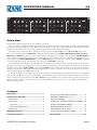
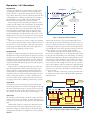
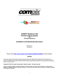
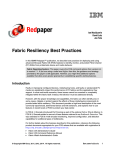
-20 oct BANDWIDTH 5 10 1 0.5 2 ATTACK ms Hz 3.15k 20k FREQUENCY PEQ 20 640 Auto 2s 1s 10 5 RELEASE 25 125 Auto 500 ms 25 50 500 250 50 125 n:1 100 1 1.5 2 -12 4 2 dB GAIN 0 +12 Soft KNEE dB +12 +6 -20 dBu +22 +10 dB SIDE-CHAIN Comp Listen Headroom LIMIT THRESHOLD -40 LIMIT 0 1 LINK 24 12 6 3 MASTER BYPASS -10 ACTIVE 1 -30 Reduction dB 0 8 GAIN Hard -12 -6 -1 TH 18 12 RATIO dBu +20 +10 0 -3 COMP THRESHOLD -40 -30 -10 dBr -12 -6 2 dBu -10 +20 +10 0 dBr oct 2 5 10 125 ms 500 n:1 Hz 3.15k 20k FREQUENCY PEQ 20 125 640 Auto 2s 1s 10 5 RELEASE 25 50 Auto 500 250 BANDWIDTH 0.5 1 ms 100 ATTACK 25 50 1 2 -12 8 4 2 dB GAIN 0 +12 Soft KNEE dB +12 +6 -40 -30 -20 dBu +22 +10 0 LIMIT BYPASS -10 ACTIVE 1 dB SIDE-CHAIN Comp Listen Dynamic EQ Headroom LIMIT THRESHOLD Reduction dB 0 GAIN Hard -12 -6 -1 TH 18 12 RATIO -3 1.5 -12 -6 COMP THRESHOLD -40 -30 -20 SLAVE 24 12 6 3 -20 dBu +20 +10 0 oct 2 5 10 125 1 ms Hz 3.15k 20k FREQUENCY PEQ 20 125 640 Auto 2s 1s 10 5 RELEASE 25 500 n:1 2 -12 4 2 dB GAIN 0 +12 Soft KNEE dB +12 +6 -20 dBu +22 +10 dB SIDE-CHAIN Comp Listen Dynamic EQ Headroom LIMIT THRESHOLD -40 LIMIT 0 3 LINK 24 12 6 3 MASTER BYPASS -10 ACTIVE 1 -30 Reduction dB 0 8 GAIN Hard -12 -6 -1 TH 18 12 RATIO -3 1.5 50 Auto 500 250 BANDWIDTH 0.5 1 ms 100 ATTACK 25 50 COMP THRESHOLD -40 -30 -10 dBr -12 -6 4 dBu -10 +20 +10 0 dBr oct 2 5 10 125 ms 500 n:1 5 Hz 3.15k 20k FREQUENCY PEQ 20 125 640 Auto 2s 1s 10 RELEASE 25 50 Auto 500 250 BANDWIDTH 0.5 1 ms 100 ATTACK 25 50 1 -12 4 2 dB GAIN 0 +12 Soft KNEE dB +12 +6 -20 dBu +22 dB SIDE-CHAIN Comp Listen Dynamic EQ Headroom LIMIT THRESHOLD -40 +10 0 LIMIT BYPASS -10 ACTIVE 1 -30 Reduction dB 0 8 GAIN Hard -12 -6 -1 TH 18 12 2 RATIO -3 1.5 -12 -6 COMP THRESHOLD -40 -30 -20 SLAVE C4 POWER QUAD COMPRESSOR 24 12 6 3 COMPRESSOR / LIMITER / DYNAMIC EQ C4 IMPORTANT SAFETY INSTRUCTIONS 1. Read these instructions. 2. Keep these instructions. 3. Heed all warnings. 4. Follow all instructions. 5. Do not use this apparatus near water. 6. Clean only with a dry cloth. 7. Do not block any ventilation openings. Install in accordance with manufacturer’s instructions. 8. Do not install near any heat sources such as radiators, registers, stoves, or other apparatus (including amplifiers) that produce heat. 9. Do not defeat the safety purpose of the polarized or grounding-type plug. A polarized plug has two blades with one wider than the other. A grounding-type plug has two blades and a third grounding prong. The wide blade or third prong is provided for your safety. If the provided plug does not fit into your outlet, consult an electrician for replacement of the obsolete outlet. 10. Protect the power cord and plug from being walked on or pinched particularly at plugs, convenience receptacles, and the point where it exits from the apparatus. 11. Only use attachments and accessories specified by Rane. 12. Use only with the cart, stand, tripod, bracket, or table specified by the manufacturer, or sold with the apparatus. When a cart is used, use caution when moving the cart/apparatus combination to avoid injury from tip-over. 13. Unplug this apparatus during lightning storms or when unused for long periods of time. 14. Refer all servicing to qualified service personnel. Servicing is required when the apparatus has been damaged in any way, such as power supply cord or plug is damaged, liquid has been spilled or objects have fallen into the apparatus, the apparatus has been exposed to rain or moisture, does not operate normally, or has been dropped. 15. The plug on the power cord is the AC mains disconnect device and must remain readily operable. To completely disconnect this apparatus from the AC mains, disconnect the power supply cord plug from the AC receptacle. 16. This apparatus shall be connected to a mains socket outlet with a protective earthing connection. 17. When permanently connected, an all-pole mains switch with a contact separation of at least 3 mm in each pole shall be incorporated in the electrical installation of the building. 18. If rackmounting, provide adequate ventilation. Equipment may be located above or below this apparatus, but some equipment (like large power amplifiers) may cause an unacceptable amount of hum or may generate too much heat and degrade the performance of this apparatus. 19. This apparatus may be installed in an industry standard equipment rack. Use screws through all mounting holes to provide the best support. WARNING: To reduce the risk of fire or electric shock, do not expose this apparatus to rain or moisture. Apparatus shall not be exposed to dripping or splashing and no objects filled with liquids, such as vases, shall be placed on the apparatus. WARNING The symbols shown below are internationally accepted symbols that warn of potential hazards with electrical products. CAUTION RISK OF ELECTRIC SHOCK DO NOT OPEN ATTENTION: RISQUE DE CHOCS ELECTRIQUE - NE PAS OUVRIR To reduce the risk of electrical shock, do not open the unit. No user serviceable parts inside. Refer servicing to qualified service personnel. This symbol indicates that a dangerous voltage constituting a risk of electric shock is present within this unit. This symbol indicates that there are important operating and maintenance instructions in the literature accompanying this unit. WARNING: This product may contain chemicals known to the State of California to cause cancer, or birth defects or other reproductive harm. NOTE: This equipment has been tested and found to comply with the limits for a Class B digital device, pursuant to part 15 of the FCC Rules. These limits are designed to provide reasonable protection against harmful interference in a residential installation. This equipment generates, uses and can radiate radio frequency energy and, if not installed and used in accordance with the instructions, may cause harmful interference to radio communications. However, there is no guarantee that interference will not occur in a particular installation. If this equipment does cause harmful interference to radio or television reception, which can be determined by turning the equipment off and on, the user is encouraged to try to correct the interference by one or more of the following measures: • Reorient or relocate the receiving antenna. • Increase the separation between the equipment and receiver. • Connect the equipment into an outlet on a circuit different from that to which the receiver is connected. • Consult the dealer or an experienced radio/TV technician for help. CAUTION: Changes or modifications not expressly approved by Rane Corporation could void the user's authority to operate the equipment. This Class B digital apparatus complies with Canadian ICES-003. Cet appareil numérique de la classe B est conforme à la norme NMB-003 du Canada. INSTRUCTIONS DE SÉCURITÉ 1. Lisez ces instructions. 2. Gardez précieusement ces instructions. 3. Respectez les avertissements. 4. Suivez toutes les instructions. 5. Ne pas utiliser près d’une source d’eau. 6. Ne nettoyer qu’avec un chiffon doux. 7. N’obstruer aucune évacuation d’air. Effectuez l’installation en suivant les instructions du fabricant. 8. Ne pas disposer près d’une source de chaleur, c-à-d tout appareil produisant de la chaleur sans exception. 9. Ne pas modifier le cordon d’alimentation. Un cordon polarisé possède 2 lames, l’une plus large que l’autre. Un cordon avec tresse de masse possède 2 lames plus une 3è pour la terre. La lame large ou la tresse de masse assurent votre sécurité. Si le cordon fourni ne correspond pas à votre prise, contactez votre électricien. 10. Faites en sorte que le cordon ne soit pas piétiné, ni au niveau du fil, ni au niveau de ses broches, ni au niveau des connecteurs de vos appareils. 11. N’utilisez que des accessoires recommandés par Rane. 12. N’utilisez que les éléments de transport, stands, pieds ou tables spécifiés par le fabricant ou vendu avec l’appareil. Quand vous utlisez une valise de transport, prenez soin de vous déplacer avec cet équipement avec prudence afin d’éviter tout risque de blessure. 13. Débranchez cet appareil pendant un orage ou si vous ne l’utilisez pas pendant un certain temps. 14. Adressez-vous à du personnel qualifié pour tout service après vente. Celui-ci est nécessaire dans n’importe quel cas où l’appareil est abimé : si le cordon ou les fiches sont endommagés, si du liquide a été renversé ou si des objets sont tombés sur l’appareil, si celui-ci a été exposé à la pluie ou l’humidité, s’il ne fonctionne pas correctement ou est tombé. 15. La fiche du cordon d’alimentation sert à brancher le courant alternatif AC et doit absolument rester accessible. Pour déconnecter totalement l’appareil du secteur, débranchez le câble d’alimentation de la prise secteur. 16. Cet appareil doit être branché à une prise terre avec protection. 17. Quand il est branché de manière permanente, un disjoncteur tripolaire normalisé doit être incorporé dans l’installation électrique de l’immeuble. 18. En cas de montage en rack, laissez un espace suffisant pour la ventilation. Vous pouvez disposer d’autres appareils au-dessus ou en-dessous de celuici, mais certains (tels que de gros amplificateurs) peuvent provoquer un buzz ou générer trop de chaleur au risque d’endommager votre appareil et dégrader ses performances. 19. Cet appareil peut-être installé dans une baie standard ou un chassis normalisé pour un montage en rack. Visser chaque trou de chaque oreille de rack pour une meilleure fixation et sécurité. ATTENTION: afin d’éviter tout risque de feu ou de choc électrique, gardez cet appareil éloigné de toute source d’humidité et d’éclaboussures quelles qu’elles soient. L’appareil doit également être éloigné de tout objet possédant du liquide (boisson en bouteilles, vases,…). ATTENTION CAUTION RISK OF ELECTRIC SHOCK DO NOT OPEN ATTENTION: RISQUE DE CHOCS ELECTRIQUE - NE PAS OUVRIR Afin d’éviter tout risque de choc électrique, ne pas ouvrir l’appareil. Aucune pièce ne peut être changée par l’utilisateur. Contactez un SAV qualifié pour toute intervention. Les symboles ci-dessous sont reconnus internationalement comme prévenant tout risque électrique. Ce symbole indique que cette unité utilise un voltage élevé constituant un risque de choc électrique. Ce symbole indique la présence d’instructions d’utilisation et de maintenance importantes dans le document fourni. REMARQUE: Cet équipement a été testé et approuvé conforme aux limites pour un appareil numérique de classe B, conformément au chapitre 15 des règles de la FCC. Ces limites sont établis pour fournir une protection raisonnable contre tout risque d’interférences et peuvent provoquer une énergie de radiofréquence s'il n'est pas installé et utilisé conformément aux instructions, peut également provoquer des interférences aux niveaux des équipements de communication. Cependant, il n'existe aucune garantie que de telles interférences ne se produiront pas dans une installation particulière. Si cet équipement provoque des interférences en réception radio ou télévision, ceci peut être detecté en mettant l'équipement sous/hors tension, l'utilisateur est encouragé à essayer de corriger cette interférence par une ou plusieurs des mesures suivantes: • Réorienter ou déplacer l'antenne de réception. • Augmenter la distance entre l'équipement et le récepteur. • Connecter l'équipement à une sortie sur un circuit différent de celui sur lequel le récepteur est branché. • Consulter un revendeur ou un technicien radio / TV expérimenté. ATTENTION: Les changements ou modifications non expressément approuvés par Rane Corporation peuvent annuler l'autorité de l'utilisateur à manipuler cet équipement et rendre ainsi nulles toutes les conditions de garantie. Cet appareil numérique de classe B est conforme à la norme Canadienne ICES-003. Cet appareil numérique de classe B est conforme à la norme Canadienne NMB-003. OPERATORS MANUAL C4 QUAD COMPRESSOR / LIMITER -12 -6 -3 -1 TH 18 12 8 2 Reduction dB 0 4 2 1 1 LINK MASTER -20 dBr -10 0 -30 1.5 +10 -40 +20 1 dBu COMP THRESHOLD 250 25 500 ms -6 10 -12 RATIO 100 50 n:1 5 125 500 25 ms Auto RELEASE -30 Hard Soft KNEE 1 125 dBu +22 +10 1 COMP THRESHOLD 24 dB 250 25 500 ms 125 Headroom 4 2 10 -12 500 +6 oct 10 BANDWIDTH 20 Hz 20k FREQUENCY PEQ dB GAIN 0.5 +12 SIDE-CHAIN -3 -1 TH 18 12 8 2 Reduction dB 0 25 ms Auto RELEASE Hard Soft KNEE 5 oct 10 12 24 dB Hz 250 25 500 ms 4 2 20k dB GAIN +12 Comp Listen Dynamic EQ SIDE-CHAIN 10 -12 500 +6 3 1 LINK 25 ms Auto RELEASE Soft KNEE oct 10 BANDWIDTH 12 dBu +22 24 dB Hz 20k 250 25 500 ms dB GAIN 125 Headroom Comp Listen Dynamic EQ SIDE-CHAIN 4 2 n:1 10 -12 500 +6 1 25 ms Auto RELEASE 5 oct 10 3 -10 -30 Hard Soft KNEE 6 0 12 +10 -40 dBu +22 24 dB LIMIT THRESHOLD Headroom Hz C4 QUAD COMPRESSOR 0 3.15k 125 20 LIMIT -20 640 BANDWIDTH BYPASS GAIN 1s Auto 0.5 ACTIVE +12 dB 2s 2 +12 Reduction dB 0 -6 50 ATTACK 1 -12 8 5 RATIO 100 50 0 FREQUENCY PEQ 1 COMP THRESHOLD LIMIT THRESHOLD 3.15k 125 20 -40 +10 +20 6 +10 -1 TH 18 12 2 1.5 dBu 0 -3 dBr 0 -40 3 -10 -30 Hard -12 -6 -10 -30 LIMIT -20 640 5 0.5 BYPASS GAIN 2s 4 SLAVE -20 ACTIVE +12 dB 1s 50 2 1 -12 -6 Auto 0 FREQUENCY PEQ 125 ATTACK Headroom n:1 5 RATIO 100 50 LIMIT THRESHOLD 3.15k 125 20 dBu 1 COMP THRESHOLD 6 0 +22 +20 dBu +10 -40 1.5 +10 -40 3 -10 0 -30 LIMIT -30 640 BANDWIDTH BYPASS dBr -10 -20 ACTIVE -20 Auto 1 -12 -12 -6 GAIN 1s Comp Listen 0.5 1 +12 dB 2s 2 3.15k -6 50 ATTACK LIMIT THRESHOLD n:1 5 RATIO 100 50 0 640 5 12 8 Reduction dB 0 1.5 +20 6 +10 -40 0 dBu 0 -1 TH 18 12 2 MASTER -40 3 -10 -3 dBr -10 -30 LIMIT -20 Auto 2 BYPASS GAIN 2s -12 -6 -20 ACTIVE +12 dB 1s 50 ATTACK +6 2 SLAVE 20k FREQUENCY PEQ POWER -12 dB GAIN +12 Comp Listen Dynamic EQ SIDE-CHAIN Quick Start Rejected Rane advertising slogan #1743: “C4. It’ll blow your mind!” We’re not entirely sure why the marketing department didn’t like the idea, but be assured: unlike its explosive material namesake, the C4 Quad Compressor will not blow up. Heck, it won’t even spark or sizzle under normal circumstances. The only thing smokin’ will be your mix, thanks to the C4’s smooth compression, precise dynamic EQ and ultra-fast limiting. Each of the C4’s four channels offers a full-featured compressor with selectable Compressor and Dynamic EQ modes. In addition, an oversampled, brick wall LIMITER is included for catching signal peaks. COMP, THRESHOLD, RATIO, ATTACK, RELEASE and KNEE give full control over the audio envelope. The compressor is toggled on and off using the ACTIVE/BYPASS switch; the Limiter is engaged at all times and is not affected by this switch. Limiter operation is completely independent of the compressor with its own LIMIT THRESHOLD control and Headroom meter. Channels 1 & 2, and 3 & 4 can be LINKed to maintain a proper left/right stereo image, with channels 1 and 3 acting as the MASTERs, respectively. For the ultimate in dynamics processing flexibility, the C4 includes both internal and external side-chain functions, with a full PEQ (parametric EQ) section included for good measure. External side-chain mode is automatically selected whenever a connector is plugged into the rear panel SIDE-CHAIN jack. Selecting LISTEN mode routes the side-chain audio to the channel output, allowing you to hear the effect of PEQ adjustments when doing frequency-sensitive compression or de-essing. If you'd prefer to not use the side-chain PEQ, simply set the PEQ GAIN to 0 dB. Setting up the C4 is a breeze thanks to the fast, accurate side-chain and Gain Reduction combination meter. For users unfamiliar with de-essing, the pointer on each control indicates a recommended setting for this specialized application. The Auto attack and release mode speeds up sound check, and the Tips and Tricks on page Manual-8 serve as a handy reference guide for getting started with compression. Thank you for taking the time to read this Quick Start. We now return you to your regularly scheduled sound check or recording session. Contents Quick Start.....................................................................1 Dynamics 101 Revisited.............................................2 Compression......................................................................2 Dynamic EQ.......................................................................3 De-essing.......................................................................3 Dynamic EQ Applications..........................................4 Peak Limiting......................................................................5 Making Connections...................................................6 Front Panel Controls..................................................6 WEAR PARTS: This product contains no wear parts. Side-chain and Gain Reduction Meters......................6 MASTER / SLAVE Stereo Link......................................7 ACTIVE / BYPASS...........................................................7 COMPressor THRESHOLD, RATIO and GAIN.......8 ATTACK, RELEASE and KNEE.....................................8 SIDE-CHAIN Mode and Listen.....................................9 SIDE-CHAIN Parametric EQ.........................................9 Limit Threshold and Headroom Meter.......................10 Tips and Tricks............................................................10 Manual-1 Dynamics 101 Revisited Compression A compressor, when the input signal reaches the level set by the threshold control, begins turning down the signal by an amount set by the ratio control. Modern compressors make the loud signals quieter, but do not make the quiet parts louder. (However, by keeping the loud signals under control, you can turn up the output level, which will make the quiet parts louder along with the rest of the signal.) Primary uses are 1) reduce dynamic range of vocalists and other musical instruments that exceed the recording or reproduction capability; 2) prevent clipping and distortion in live sound systems or recording chains; 3) smooth and balance an instrument such as a bass guitar with wide dynamic range and string-to-string level variations; 4) reduce vocal sibilance (deesser); 5) produce louder recordings for broadcast; and 6) evenout paging variations due to different speakers in large systems. COMPRESSOR -10 Output Level dBu Introduction Compressors and limiters are in the business of automatically controlling the volume or dynamics of sound, just like your hand on the fader, or the fat man dancing in front of the midrange cabinet. Used wisely, often in conjunction with each other or with equalization or filtering, dynamics processors improve the intelligibility of voice and the subjective effect of music. However, in the wrong hands they can sound terrible. Heavy compression (low threshold and a high ratio) often sounds nasty. The timbre of the sound changes, becoming hard and closed and not nearly as sweet and open as the sounds you envisioned when you got into this business. On the other hand, attack times optimized for pleasant compression may not track initial transients quick enough. In addition, pumping and breathing may accompany heavy compression, i.e., the background noise rises way out of proportion to the foreground sound as the compressor releases. Result: it just does not sound good. Therefore, no matter how you slice it, compressors and limiters are just fancy electronic volume controls. Think of them as an extra hand on a control, turning the volume down and turning it back up again. Luckily, this electronic hand is quick and accurate, but it is just adjusting a volume control. 0 The Ratio controls the amount of gain reduction above the Threshold -20 2 1.5 1 5 n:1 Side-chain The side-chain is the hand that controls the volume. Side-chain circuitry, also known as the detector, examines the input signal and issues a control message to adjust the gain of the main signal path. Full-featured compressors, like the C4, offer both internal and external side-chain options. When the internal option is selected the compressor’s input signal feeds the detector. This arrangement works well for most applications, and is especially Manual-2 10 RATIO Limiter = ∞:1 :1 =2 -20 -10 -30 -40 0 +10 dBu +22 LIMIT THRESHOLD The Limiter Threshold controls the hinge point of a Ratio set at ∞:1 :1 1 at et ss -40 io at ll R -50 -60 io Rat sor s pre Com -30 g in No s es oc pr -60 — a -20 -10 -30 0 +10 -40 +20 dBu COMP THRESHOLD The Compressor Threshold controls the hinge point -50 -40 -30 -20 -10 0 +10 +20 Input Level dBu Figure 1. Compressor and Limiter functions effective with the C4 due to the parametric EQ built into the side-chain. The external side-chain allows any signal source, connected to a dedicated input jack, to feed the detector, thereby determining the compressor’s response. This external signal may be a specially filtered version of the input signal, using an outboard EQ for example, or it may be another signal altogether. It is important that the side-chain signal is not heard. For instance, if you added treble boost to the side-chain audio (either by using the C4’s built-in PEQ or an outboard EQ), it would not affect the high frequencies in the main signal path, but it would cause them to cross the threshold sooner and more often. Large peaks of treble would cause heavy compression with no compression at other times. This example is the basic de-esser, a circuit to remove excess sibilance. (There is a much more sophisticated and effective de-esser built-into the C4, but more on that later.) With a bass boost, you can make a de-thumper, and with a midrange boost a de-nasaler. There are a number of parameters governing side-chain activity, but the four primary ones are Threshold, Ratio, Attack time and Release time. BROADBAND GAIN CONTROL INPUT Signal Path A compressor has two internal paths: the signal and the sidechain. The signal path is the route the main signal takes through the unit: from the input circuits to the gain control section and exits through the output circuits. The signal chain goes through the “volume control” in the “hand on a control” analogy. LIMITER THRESHOLD OUTPUT RATIO ATTACK RELEASE SCALE FILTER FREQ BW GAIN SIDE-CHAIN EQ RMS DETECTOR GAIN COMPUTER SIDE-CHAIN Figure 2. Frequency sensitive compressor block diagram. Dynamic EQ Dynamic EQ differs from the forms of compression listed above in that it dynamically controls the boost/cut of a parametric filter rather than broadband frequency gain. The basic dynamic EQ uses a bandpass filter in the side-chain with variable center frequency and bandwidth. The side-chain detector is sensitive only to the passband frequencies. A parametric filter with matching bandwidth and center frequency is placed in the main signal path and the boost/cut of the filter is controlled the same way a broadband compressor boosts or cuts broadband gain. Relative Threshold Dynamic EQ Relative Threshold Dynamic EQ is a special form of dynamic EQ where the rms level of the bandpass signal in the side-chain is compared to the rms level of the broadband signal. The difference between the bandpass and broadband levels is compared to the threshold rather than the absolute rms value of the bandpass signal. The advantage of this type of dynamic EQ is that the relative amplitude of a band of frequencies, as compared to the broadband level, is maintained regardless of broadband amplitude. The typical topology is shown in Figure 3. signal, then setting a threshold based on this difference, therefore it is our experience that Relative Threshold Dynamic EQ (as described above) is the best dynamics processor for this task as it is able to maintain proper sibilant to non-sibilant balance regardless of level. A good de-esser looks at the average level of the broadband signal (20 Hz to 20 kHz) and compares it to the average level of a bandpass filter in the side-chain. The threshold setting defines the relative threshold, or difference, between broadband and bandpass levels, which result in compression of sibilants. Because de-essing depends on the ratio of sibilant to broadband signal levels, it is not affected by the absolute signal level, allowing the de-esser to maintain the correct ratio of broadband to sibilant material regardless of signal level, as shown in Figure 4. 0 -2.5 -5 -7.5 -10 -12.5 L e v e l d B u -15 -17.5 -20 -22.5 Increasing Level -25 De-essing -27.5 -30 -32.5 -35 -37.5 -40 INPUT -42.5 OUTPUT -45 20 50 100 200 PARAMETRIC EQ THRESHOLD BROADBAND BANDPASS RMS DETECTOR BROADBAND RMS DETECTOR SCALE 1k 2k 5k 10k 20k Figure 4. The C4’s De-essing performance remains consistent with varying input levels. RATIO ATTACK RELEASE FREQ BW BANDPASS 500 Frequency (Hz) FILTER GAIN COMPUTER SIDE-CHAIN This means that the de-essing performance is consistent and predictable, regardless of how loud or quiet the singer/talker is. Taming sibilance when the talker is quiet is just as important as when the talker is at a fevered pitch. Figure 5 shows what happens using a primitive de-esser with a side-chain EQ. Sibilance during loud passages is attenuated, but there is no gain reduction during quiet passages, even though there may still be a significant amount of “sss” in the person’s voice. For a given threshold, this often results in an overly aggressive effect during the loud choruses, and a completely ineffective result during the hissy, whispered verses. Figure 3. Relative threshold dynamic EQ block diagram. 0 -2.5 -5 De-essers De-essing limits or controls the sibilant content of speech. Sibilance produces a hissing sound. English sibilant speech sounds are (s), (sh), (z), or (zh). De-essing is often confused as a type of dynamics processor. It’s actually a specific application that is accomplished using many different types of dynamics processors. And contrary to popular belief, successful de-essing is not as simple as placing a bandpass or treble-boost filter in the side-chain and calling it done. Frequency Sensitive Compression, Split-Band Compression, Dynamic EQ and Relative Threshold Dynamic EQ are all used for de-essing. True de-essing involves comparing the relative difference between the troublesome sibilants and the overall broadband -7.5 -10 -12.5 L e v e l d B u De-essing -15 -17.5 -20 -22.5 Increasing Level -25 No De-essing -27.5 -30 -32.5 -35 -37.5 -40 -42.5 -45 20 50 100 200 500 1k 2k 5k 10k 20k Frequency (Hz) Figure 5. Primitive de-esser with a simple side-chain. Varying input levels adversely affects de-essing. Manual-3 Dynamic EQ Applications Auto-Correct Microphone Proximity Effect Use Dynamic EQ to automatically correct for timbre changes due to the low frequency boost caused by the proximity effect of cardioid microphones (see Figure 6), which occurs when a singer/speaker does not remain a consistent distance from the microphone. Two opposite applications share this problem: 1. The first occurs when the mic is located far enough from the person that the proximity effect has no bearing (typically a podium situation), then the speaker leans in closer to the microphone causing a low frequency boost. Start with a 100 – 250 Hz center frequency, a bandwidth of 2 octaves and a ratio of 3:1. Set the threshold high enough so when the person is the normal distance there is no response, and only when they move closer to the mic does the threshold kick the filter into action. 2. The second application compensates for the loss of proximity effect as the person moves the microphone away from their mouth; typical of most hand held mics. Solve this problem by perform the opposite routine as the podium mic example above. Have the person hold the microphone at the farthest distance from their mouth that can occur. Set the Dynamic EQ so that it is just below threshold. Once they move the mic closer to their mouth it will reduce the low frequency boost. Since we have become accustomed to hearing the proximity effect try low ratios so that the tonality change is slight, but remains more consistent than without the Dynamic EQ. Use appropriate EQ on the input channel to add back in any missing warmth – this warms the signal while the Dynamic EQ keeps the tonality consistent. Typical starting points are a frequency of 100 – 250 Hz, a bandwidth of 2.0 octaves and a ratio of 2:1 depending on the desired change in tonality. Figure 6. Microphone Proximity Effect (courtesy of Shure Inc.) Low frequencies rise as the sound source gets closer to a cardioid microphone. Manual-4 Auto-EQ Changing Sound Sources A great example is evening out the tone, or timbre, of a guitar amplifier. Using two channels set up for different tones is very common to switch between a rhythm tone and a lead tone. Often the musician sets the lead tone brighter than the rhythm tone so it cuts through better. The problem comes when the sound system amplifies this all out of proportion, resulting in too much energy around 2 kHz – 4 kHz (a really nasty frequency range due to the ear’s maximum sensitivity to this octave). Setting the Dynamic EQ for a center frequency of 3 kHz and a bandwidth of about 1 octave cleans this up. Set the threshold high enough so that during normal playing nothing is happening. If the device uses relative threshold, once the lead channel is used it will automatically see the change in timbre and apply the Dynamic EQ to reduce the excess energy at 3 kHz relative to the rest of the audio spectrum. You can also use this technique to make guitar sounds “thick” and “chunky” without being overbearing by using the EQ section set in the 200 Hz range as well. Improve Vocals It is common for female singers to have a wide tonality swing when shifting from a quiet breathy passage to a loud crescendo. The voice sounds warm and pleasant during the quiet passage but shows a predominance of frequencies in the 1.2 kHz range for the loud crescendo. This is exaggerated when the singer moves the microphone away from her mouth thereby removing the warming character of the microphone’s proximity effect and adds to the naturally occurring peak in this frequency range. To fix this, simply set the EQ section to the problem frequency (typically 1.2 kHz) and set the threshold so that the compressor only kicks in when she sings the loud passages. Use the ratio control to determine exactly how much of the original tone change remains – low ratios leave more change while high ratios clamp down hard and allow very little change. Create Radical Sounds Dynamic EQ lets the user create sounds that change tone with level, or at extreme settings, which allows the creation of radical sounds based on the threshold, attack & release times. Experiment – the results will amaze you. Peak Limiting A limiter is just a compressor with a really high ratio, right? Well…not exactly. Although the two devices use similar terminology (Threshold, Attack, Release, and so on), they serve two completely different purposes and therefore operate in different manners. Fundamentally, a compressor uses an rms detector to keep the average level of a signal under control, while a limiter uses a peak detector to act on the instantaneous level of the signal. Compare Figure 2 to Figure 7. Primary uses of limiters: 1) preventing clipping and distortion in power amplifiers, 2) protection of loudspeakers from damage resulting from destructive transients [like the proverbial dropped microphone] 3) preventing overs [clipping] during digital recording 4) preventing overmodulation of the transmitted signal in broadcast. Figure 8 shows the effect of limiting a signal. The top line is the original, full volume input signal we need to limit – perhaps the unfortunate blast of noise when the vocalist inadvertently unplugs the phantom-powered mic. The bottom line shows the limited output. At no point does the output signal ever exceed the threshold, demonstrating the limiter’s brick wall capability. Contrast this with Figure 9, which shows a compressor set to a high ratio (∞:1), and a fast attack time. Due to the compressor’s averaging effect, the output easily overshoots the threshold, and transient peaks are missed altogether. And it’s these peaks which can potentially ruin your speakers or the perfect recording take, and possibly your reputation. Input Limit Threshold Output Figure 8. Limiter performance showing brick wall characteristic. Input Limit Threshold Overshoot Output Figure 9. Compressor used as a limiter. Signal peaks can still exceed threshold, even at high ratio settings. BROADBAND GAIN CONTROL INPUT OUTPUT +20 THRESHOLD RELEASE +15 +10 +5 PEAK DETECTOR FILTER O 0 u t -5 p -10 u t -15 d B -20 u -25 -30 GAIN COMPUTER -40 SIDE-CHAIN Figure 7. Peak Limiter Block Diagram Threshold -35 -40 -35 -30 -25 -20 -15 -10 Input dBu -5 0 +5 +10 +15 +20 Figure 10. Peak Limiter Response Graph Manual-5 Making Connections Front Panel Controls The C4 features auto balanced/unbalanced XLR and ¼" TRS input and output jacks, permitting connection to virtually any mixing console. Side-chain inputs are also auto balanced/unbalanced, on ¼" TRS only. Dynamics processors typically connect using a mixing console’s insert points (send/return), although they can be used in-line, such as when compressing or limiting an overall mix, for example. Each channel of the C4 features the following meters and controls: MIC MIC INPUT CH 1 INPUT INSERT RETURN CH 1 OUTPUT BASS INSTRUMENT IN CH 2 INPUT INSERT SEND CH 2 OUTPUT SUB GROUP 1 CH 3 SIDE-CHAIN INSERT SEND CH 3 INPUT CH 3 OUTPUT INSERT RETURN MASTER STEREO LINK SLAVE SUB GROUP 2 CH 4 SIDE-CHAIN INSERT SEND CH 4 INPUT CH 4 OUTPUT INSERT RETURN C4 MIXER GRAPHIC EQ MASTER CONTROL 4 6 0 10 2 OL INSERT SEND ±12 8 LEVEL ±6 BYPASS RANGE + 6 4 2 1 0 1 2 4 6 – 25 31.5 40 50 63 80 100 125 160 200 250 315 400 500 630 800 1k 1.25k 1.6k 2k 2.5k 3.15k 4k 5k 6.3k 8k 10k 12.5k 16k 20k + 12 8 5 2 0 2 5 8 12 – ME 30B MICROGRAPHIC EQUALIZER POWER CH 1 SIDE-CHAIN CH 1 INPUT INSERT RETURN CH 1 OUTPUT C4 MIXER Figure 12. Using an external equalizer in the side-chain. + 1-CONDUCTOR SHIELDED CABLE dBr T = SEND R = RETURN S = SHIELD 1-CONDUCTOR SHIELDED CABLE SHIELD Send/Return Cable Wiring (Insert Cable) Manual-6 8 4 2 1 Reduction dB + SEND SHIELD + -1 TH 18 12 Gain Reduction Display The Gain Reduction meter displays the amount of gain correction presently applied to the signal, lighting from right to left as the amount of gain reduction increases. In Compressor mode, this meter display the amount of gain correction being applied to the broadband program material. In De-ess mode. this meter shows the amount of gain correction being applied to the dynamic EQ (DEQ) in the main signal chain. This meter does not reflect any gain reduction occurring due to limiting. Gain Reduction meter ballistics follow the actual gain correction value as determined by the THRESHOLD, RATIO, ATTACK, RELEASE and KNEE controls. Gain reduction may be indicated when the Threshold indicator is off, as attack and decay rates may dictate continued gain reduction even when the rms level is below threshold. Figure 11. Connection to a mixing console. MIC INPUT -3 Side-chain Level Display In Compressor mode, the floating meter displays the side-chain level relative to the Threshold (dBr), making it easy to gauge how close the signal is to the onset of compression. The dBr indicators light from left to right as the signal approaches the threshold. At threshold, the yellow TH indicator is lit. Above threshold the TH indicator remains lit and gain reduction occurs. Side-chain meter ballistics follow the rms detector time constant of 30 ms. In Dynamic EQ mode, the side-chain meter displays the relative difference between the broadband program material and the bandpass signal defined by the PEQ, as compared to the set Threshold. Example: With THRESHOLD set to -15 dB, the TH indicator lights when the sibilant portion of the program material is 15 dB below the broadband program material. If the sibilants are 18 dB below the broadband material, then the –3 dBr indicator is lit. CH 2 SIDE-CHAIN INSERT RETURN -12 -6 This triple-function meter displays the side-chain level, threshold indication and amount of gain reduction being applied. It allows you to see at a glance exactly what the compressor is doing at all times. CH 1 SIDE-CHAIN INSERT SEND Side-chain and Gain Reduction Meters + SHIELD RETURN MASTER / SLAVE Stereo Link 1 2 3 SLAVE MASTER LINK MASTER When channels are Linked • Bypassing the Master channel does not automatically bypass the Slave channel. Channel ACTIVE / BYPASS switches are the only controls which do not follow the Master channel, making it possible to bypass each channel individually. 4 LINK SLAVE The MASTER / SLAVE switches link channels 1 & 2, or channels 3 & 4 for stereo operation. When linked, the associated LINK indicator lights and only the controls of the Master channel (channel 1 or channel 3) are active, with the exception of channel ACTIVE / BYPASS switches. This feature helps preserves a stable left/right image when compressing a stereo source, such as a vocal or horn submix. -12 -6 -3 -1 TH 18 12 8 4 2 1 1 LINK MASTER -20 dBr -10 -30 1.5 +10 -40 +20 1 dBu COMP THRESHOLD 250 25 500 n:1 5 -6 10 -12 RATIO 100 50 ms Reduction dB 0 2 0 125 500 +12 dB -20 1s ms Auto RELEASE Soft KNEE 2 0.5 oct 10 BANDWIDTH 12 24 dB Hz +10 20k FREQUENCY PEQ -12 dB GAIN 1 250 25 500 SIDE-CHAIN 2 Reduction dB 0 ms n:1 5 -6 10 -12 4 2 1 125 500 ms Auto RELEASE 0.5 oct 10 BANDWIDTH 20 -10 -30 Hard Soft KNEE 640 125 BYPASS ACTIVE 6 0 12 +10 -40 dBu +22 24 dB LIMIT THRESHOLD Headroom 0 3.15k Hz 20k FREQUENCY PEQ -12 dB GAIN BYPASS LIMIT -20 1s Auto 5 ACTIVE 3 2s 25 ATTACK +6 +12 dB GAIN 50 2 +12 8 RATIO 100 50 1 Comp Listen Dynamic EQ -1 TH 18 12 1.5 COMP THRESHOLD LIMIT THRESHOLD 3.15k 125 20 dBu +22 0 +20 6 0 +10 -40 -3 dBr -10 dBu 0 640 5 -12 -6 -40 Headroom Auto 1 -10 -30 Hard ACTIVE / BYPASS 2 -30 LIMIT 3 2s 25 BYPASS • Meters for Master and Slave channels remain active, indicating both channels are being processed. SLAVE -20 ACTIVE GAIN 50 ATTACK +6 • Selecting Listen on the Master channel automatically puts both channels into Listen mode. Side-chain function switch indicators are turned off on the Slave channel. +12 Comp Listen Dynamic EQ SIDE-CHAIN Figure 13. Active controls in Linked Mode Stereo Linking in Compressor Mode Linked Compressors use the rms sum of the two channels’ sidechains, and display this summed result on the side-chain dBr meters of both channels. The Master channel settings determine the actual gain reduction characteristics. Selecting BYPASS disables all Compressor/Dynamic EQ processing, including the GAIN control. The side-chain dBr meter, threshold indicator and gain reduction meter continue to operate when a channel is bypassed. Similarly, the side-chain Listen function is also available. Channels can be individually bypassed, even in Linked mode. Note: The Limiter is active at all times and is not affected by the BYPASS switch. To bypass the Limiter, simply rotate the Limiter Threshold control fully clockwise (+22 dBu setting). Linked Controls in Dynamic EQ Mode When channels are linked in Dynamic EQ mode, both channels use the Master channels’ control settings, but the dynamic EQ essentially functions independently for each channel. Combining the rms values of broadband and bandpass signals, as is done in Compressor mode, is of no advantage in Dynamic EQ mode. Stereo-Linked Limiters When channels are linked, the Master channel Limit Threshold setting determines the maximum output level for both channels. However, the greater of the two peak-detected signals is used to control the gain of both Master and Slave channels. For example, if the Slave channel signal exceeds the Mater channel’s Limit Threshold by 3 dB, both channels are limited by 3 dB. The Limit Headroom meters remain independent for both channels, as the dynamics of the Master and Slave channels may be quite different. Manual-7 COMPressor THRESHOLD, RATIO and GAIN -20 -10 -30 0 +10 -40 0 2 1.5 +20 1 dBu COMP THRESHOLD n:1 ATTACK, RELEASE and KNEE 100 5 -6 +6 50 250 10 -12 +12 25 500 RATIO dB GAIN ms 125 500 1s 50 ATTACK 2s 25 ms RELEASE Auto Hard Soft KNEE Auto The threshold, like crossing through a doorway, is the beginning point of gain adjustment. When the input signal is below the threshold, a compressor acts like a straight wire. Above threhsold, the side-chain asserts itself and turns the volume down. In Compressor mode, COMP THRESHOLD defines the absolute level, adjustable from –40 dBu to +20 dBu, above which compression begins. If soft-knee settings are used, the threshold is defined as the point at the center of the knee. (See the KNEE description for more details). In Dynamic EQ mode, this control defines the relative difference between the broadband program material and the bandpass signal defined by the PEQ. The pointer between –10 dBu and –20 dBu shows the typical setting for De-essing. RATIO defines the ratio of Input change to Output change, and is adjustable from 1:1 (straight wire, no change) to 10:1 (heavy compression), as shown in Figure 14. For example, a Ratio of 4:1 means that a 4 dB change at the input causes only a 1 dB change at the output. The pointer at 10:1 shows the typical setting for Deessing. +15 +10 +5 0 -5 -10 Ratio 10:1 -15 -20 Threshold -25 -30 -35 -40 -40 Gain Reduction x Release = 5 dB x 1 s = 0.5 s 10 dB 10 dB Auto Attack and Release Unsure about how to set the Attack and Release controls? Venue doors opening in 15 minutes and you need to speed through sound check? No problem! Simply rotate the Release control 1:1 fully clockwise until Auto is lit, indicating the Attack and Release settings are appropriately fixed for most types of program material. The C4’s not entirely on auto pilot, though – you still have full control over the Threshold, Ratio, Gain, and Knee settings. +20 O u t p u t d B u ATTACK determines how fast the gain is turned down once the signal exceeds Threshold, and is adjustable from 25 ms (fast) to 500 ms (slow). The pointer at 25 ms shows the typical setting for De-essing. RELEASE determines the rate of gain increase as less gain reduction is required, and is adjustable from 25 ms (fast) to 2 seconds (slow). It is important to understand the difference between release rate – as determined by this control – and release time. The Release setting determines how long it takes for the gain to change by 10 dB, not how long it takes to return to unity gain (no gain reduction). Example: with the Release control set to 1 s, when a signal with 5 dB of gain reduction presently applied suddenly drops below threshold, the release time is 0.5 s, calculated as follows: -35 -30 -25 -20 -15 -10 -5 0 +5 +10 +15 +20 Input dBu Figure 14. Input versus Output for various Ratio settings (hard knee) Once you reduce the dynamic range using compression, you can increase or decrease the overall loudness by adjusting the GAIN. This control features a center-detent marking the unity gain point, with a range of +12 dB or -12 dB on either side. Manual-8 We are the Knights of KNEE KNEE controls the action of the compressor above and below the threshold point. Hard knee does nothing until the signal exceeds the threshold point, then applies full compression. Soft knee begins applying a small amount of compression just before the threshold point is reached, continues increasing compression through the threshold point and beyond, finally applying full compression to the highest level signals. Depending on the application and source material, soft knee settings can sound more natural. On the other hand for maximum loudness before compression (for equipment protection for instance), use hard knee settings. Knee span is adjustable from 0 dB (Hard) to 10 dB (Soft), with the Threshold always being at the center of this span. The pointer at the Hard Knee setting shows the typical setting for De-essing. SIDE-CHAIN Parametric EQ +10 +9 +8 2 +7 1 +6 0 640 5 125 3.15k +5 +4 O u t p u t d B u 0.5 Threshold +3 +2 +1 Soft -1 -2 20 Hz 20k FREQUENCY PEQ -12 dB +12 GAIN The Side-chain PEQ filter operates in one of two ways, depending on whether the channel is operating in Compressor mode or Dynamic EQ mode. -3 -4 10 dB span -5 10 BANDWIDTH Hard 0 oct -6 -7 -8 -9 -10 -10 -9 -8 -7 -6 -5 -4 -3 -2 -1 0 +1 +2 +3 +4 +5 +6 +7 +8 +9 +10 Input dBu Figure 15. The Hard Knee compression characteristic has a 0 dB span. The Soft Knee compression characteristic has a 10 dB span. SIDE-CHAIN Mode and Listen Comp Listen Dynamic EQ SIDE-CHAIN Comp selects Compressor mode for the channel. Dynamic EQ selects this mode for the channel. Tip: A small pointer next to a control indicates a typical setting for De-essing. Listen routes the side-chain signal to the channel output, allowing you to hear exactly what the detector “hears,” and is especially useful when making precise PEQ adjustments for frequency sensitive compression or de-essing. The yellow indicator flashes when Listen is engaged, as a friendly reminder to toggle back to Comp or Dynamic EQ mode before show time. The Listen source depends on the selected mode (Comp or Dynamic EQ), so the switch operates as follows: when switching from Comp to Listen, the Comp indicator remains lit and the Listen indicator flashes, which signifies you are listening to the Compressor side-chain PEQ response. When the switch is moved to Dynamic EQ, the Listen and Comp indicators are turned off and the Dynamic EQ indicator is lit. When the switch is then moved from Dynamic EQ to Listen, the Dynamic EQ indicator remains lit and the Listen indicator flashes, which signifies you are listening to the Dynamic EQ response. Remember: once the show begins the audience never hears the filtered side-chain signal – unless you accidentally leave Listen mode engaged, of course. If something sounds a bit odd during the gig, look over at the C4 and see if any of the yellow Listen lights are flashing. If so, casually saunter over to the rack and toggle the side-chain out of Listen mode…as if you meant to have it engaged for the first six songs. PEQ in Compressor Mode In Compressor mode, the PEQ section operates as a normal, 2nd-order, parametric filter with independent BANDWIDTH, FREQUENCY and GAIN controls. The GAIN control has a center detent position indicating 0 dB, or unity gain. Use the PEQ to adjust the sensitivity of the rms detector to specific frequencies. Boosting a particular frequency makes the detector more sensitive to this frequency, while cutting makes it less sensitive. Broadband compression still takes place; the filter does not directly affect the frequency response of the main signal, as is done with the Dynamic EQ used in de-essing. Example: reducing detector sensitivity to low frequencies helps avoid the pumping and breathing often associated with compressing an overall mix of instruments. Start by engaging Listen mode and set the PEQ Gain to –12 dB with a bandwidth of 1 to 2 octaves. Adjust the frequency and bandwidth controls until most of the low frequency sound disappears (125 Hz is a good start). Oh…and don’t forget to dis-engage Listen mode when you’re done. PEQ in Dynamic EQ Mode In Dynamic EQ mode, the PEQ controls define a bandpass filter in the side-chain and a Dynamic EQ in the main signal path. The difference in the rms level of the broadband signal and that of the bandpassed side-chain signal is compared to the threshold, and the Dynamic EQ’s gain is automatically adjusted to maintain the proper ratio of sibilant to non-sibilant content. See the examples in the Dynamci EQ Applications section on page Manual-4. Manual-9 LIMIT THRESHOLD and Headroom Meter LIMIT 3 -20 -10 -30 6 0 12 +10 -40 dBu +22 Tips and Tricks -20 LIMIT THRESHOLD Headroom In addition to the Compressor / De-esser, each channel of the C4 features an independent, brick-wall Limiter with an instantaneous attack time, fixed 25 ms hold time and a fixed 6 dB/second release rate. The C4’s limiter uses oversampling in order to ensure high frequency transients are properly detected and acted upon. The Headroom meter displays the difference, in dB, between the LIMIT THRESHOLD and the present signal level. For example, with LIMIT THRESHOLD set to +10 dBu, a peak signal level of +4 dBu results in a display of 6 dB of remaining headroom (+10 dB minus +4 dB equals 6 dB). The LIMIT indicator lights when the present signal exceeds the set Limit Threshold. When setting the Limiter Threshold keep in mind that music often has peaks which are 12 to 20 dB higher than the average (rms) value, which is displayed on the side-chain meter. Note: The Limiter is active at all times and is not affected by the bypass switch. To bypass the limiter, simply rotate the Limiter Threshold control fully clockwise (+22 dBu setting). 1.5 +10 -40 +20 1 dBu n:1 COMP THRESHOLD RATIO 100 500 50 250 25 ms 0 2 0 -30 24 dB -10 125 5 -6 10 -12 ATTACK ms -20 1s Auto RELEASE 5 0.5 10 Hard Soft KNEE oct BANDWIDTH 6 0 12 +10 -40 dBu +22 24 dB LIMIT THRESHOLD Headroom 0 3.15k 125 20 -10 -30 640 1 LIMIT 3 Auto 2 BYPASS +12 dB 2s 25 ACTIVE GAIN 50 500 +6 Hz 20k FREQUENCY PEQ -12 dB GAIN +12 Comp Listen Dynamic EQ SIDE-CHAIN Initial Settings Sometimes it is necessary to start from scratch. The drawing above shows where to set the controls for no processing (the black knobs have no affect at this point). Then you can adjust each section one at a time. Suggested Settings There is no magic recipe of compressor settings which work for every audio source in every performance situation. There are, however, a few key ingredients you can add to the ol’ dynamics stew to get things going. Start with the suggested settings in Table 1, then season to taste by adjusting the Threshold until your ears tell you it’s just right. Vocals A tough issue with vocals is the extreme dynamic range of some singers. Those who can lull you to sleep and then scare you with an unexpected blast. The difference between the soft crooning and the loud climax represents too much signal change for many preamps and mixers, causing them to clip and distort badly. Compression and limiting comes to the rescue. Use the limiter to prevent the extreme levels from causing clipping and distorting the sound. With its automatic fast attack and quick release mode, all you need to set is the Limit Threshold. Set it as high as the next piece of equipment in the signal path allows. The C4 gives you a wide setting range of -40 to +22 dBu that covers all requirements. Compression is one of the most effective tricks for bringing the vocals up in any mix, live or recorded. This is due to the increase in perceived loudness which results from reducing peaks and increasing the average level. Good settings for natural sounding, yet compressed vocals, are a medium fast (25 – 50 ms) attack and a medium-slow (100 ms – 1 sec) release. Releasing too quickly sounds unnatural, while attacking too slowly misses the problem surges. Soft knee compression generally best matches vocal dynamics. Adjust the ratio to match the dynamics of the singer, with 2:1 being a good starting point. Manual-10 ATTACK RELEASE RATIO KNEE Vocals Medium to Fast Medium to Slow 2:1 to 4:1 Soft Clicky Bass Fast Fast 4:1 or higher Hard Mushy Bass Medium to Slow Medium to Slow 4:1 Hard Slow 4:1 or higher (more sustain) Hard Raging Electric Guitar Fast Acoustic Guitar Medium to Slow Medium to Slow 4:1 Medium Brassy Horns Fast Fast 5:1 or higher Hard Drums (kick, snare) Fast Fast 4:1 Hard Drums (cymbals) Fast Slow 2:1 to 10:1 Hard Table 1. Suggested Compressor Settings Bass It is common for the sound mixer to reduce the bass signal because it overwhelms the total system. Use a compressor to smooth a bass sound by lessening the variations between the strings or strongly resonant notes, and increasing sustain. Typical settings for a bass guitar are a ratio of 4:1, with a fast attack of 25 ms and a slow release of around 500 ms. These settings should produce a strong, smooth bass line to start with, but feel free to adjust further as necessary. A hard knee setting is often preferred since all that is desired is to tame the excessive peaks and leave everything else alone. Where does a compressor belong in a bass player’s signal chain? Well, that depends on how you want it to function. As a compressor/limiter for the input signal, it goes after the bass (if the bass has a line-level output) and before the preamp. If it were to function as a limiter to protect the speakers in the bass rig, it would go after the preamp and before the power amp. Another method is to insert the unit in the effect loop of the preamp. This allows the bass signal to be affected by the pre-amp first, then the compressor/limiter, and then sent to the power amp. This can be desirable with tube pre-amps. Drums Reducing the leading edge of a drum hit and bringing out more of the “body” of the drum is another popular use of compressors. Try ratios between 2:1 and 5:1 accompanied by fast attack and release times. Listen carefully while changing the attack time to find the final setting. Cymbals need a fast attack but a slow release to allow the sustain through. A low ratio of about 2:1 works well to start. Digital Recording For digital recording use the C4 to compress a too-wide dynamic range into a signal that does not cause digital overload. The Limiter is the primary tool for keeping things under control, but a little compression with its threshold set just under the limiter threshold level helps keep the limiting more subtle. To control a stereo mix, set the mode switches to Slave. Guitar Here is a suggestion on how to achieve a lower volume without sounding as if you are playing out of a transistor radio: set a slow attack time with a medium to slow release and a relatively low threshold. Experiment from these initial settings. One of the favorite uses of compression by guitarists is to increase the sustain, or duration of a note after it is played. Carlos Santana and Gabor Szabo are two musicians who use sustain to great acclaim, although they did it the old-fashioned way of creating feedback by aiming the guitar pick-ups at the loudspeaker and then jamming over it. A compressor creates a similar effect. Set a high ratio and low threshold for long sustain, along with fast attack and slow release. Again, experimentation produces the best results. ©Rane Corporation 10802 47th Ave. W., Mukilteo WA 98275-5000 USA TEL 425-355-6000 FAX 425-347-7757 WEB www.rane.com All features & specifications subject to change without notice. DOC 107487 Manual-11 -20 -20 n:1 2 -20 BANDWIDTH 10 0.5 oct 5 1 2 ATTACK 20k 3.15k ms Hz 20k 3.15k FREQUENCY PEQ 20 640 Auto 2s 1s 10 5 RELEASE 25 125 Auto 500 ms 25 50 500 250 50 125 n:1 2 100 1 1.5 -12 -12 -12 2 4 2 +12 Soft +12 +6 4 2 GAIN dB 0 +12 Soft KNEE dB GAIN +12 +6 -40 dBu +22 +10 0 LIMIT BYPASS -10 1 dB dBu +22 +10 0 LIMIT BYPASS -10 1 dB dBu +22 +10 0 LIMIT BYPASS -10 1 dB SIDE-CHAIN Comp Listen Dynamic EQ Headroom LINK 24 12 6 3 MASTER LIMIT THRESHOLD -40 -30 -20 ACTIVE 1 SIDE-CHAIN Comp Listen Dynamic EQ Headroom 24 12 6 3 LINK 24 MASTER LIMIT THRESHOLD -40 -30 -20 ACTIVE 1 SIDE-CHAIN Comp Listen Dynamic EQ Headroom LINK 12 6 3 MASTER LIMIT THRESHOLD Reduction dB 0 8 GAIN dB 0 +12 Soft KNEE dB GAIN +12 +6 -20 ACTIVE 1 -30 Reduction dB 0 8 dB 0 GAIN Hard -12 -6 dB KNEE Hard -12 -6 -1 TH 18 12 RATIO dBu +20 +10 0 -3 COMP THRESHOLD -40 -30 -10 dBr Hz 640 Auto FREQUENCY PEQ 20 125 Auto ms 2s 1s 10 5 RELEASE 25 -12 -6 BANDWIDTH 10 0.5 oct 5 1 2 ATTACK 500 ms 25 50 500 250 125 1 1.5 100 50 20k 3.15k 4 Reduction dB 0 8 GAIN Hard -12 -6 -1 TH 18 12 RATIO dBu +20 +10 0 -3 COMP THRESHOLD -40 -30 -10 dBr Hz 640 Auto FREQUENCY PEQ 20 125 Auto ms 2s 1s 10 5 RELEASE 25 -12 -6 BANDWIDTH 10 0.5 oct 5 1 2 ATTACK 500 ms 25 50 500 250 50 125 n:1 2 100 1 1.5 -1 TH 18 12 RATIO dBu +20 +10 0 -3 COMP THRESHOLD -40 -30 -10 dBr -12 -6 2 dBu -10 +20 +10 0 dBr oct 2 10 5 2 dBu -10 +20 +10 0 dBr oct 2 10 5 2 dBu -10 +20 +10 0 dBr oct 2 125 10 5 1 ms 500 n:1 2 Hz 640 20k 3.15k ms 500 n:1 RATIO 2 Hz 640 20k 3.15k Auto 2s 1s 10 5 FREQUENCY PEQ 20 125 -12 -12 -12 dB 2 4 2 +12 Soft +12 +6 4 2 GAIN dB 0 +12 Soft KNEE dB GAIN +12 +6 dBu -10 +22 +10 0 LIMIT BYPASS dB Headroom dBu -10 +22 +10 0 LIMIT BYPASS dB dBu -10 +22 +10 0 LIMIT BYPASS dB SIDE-CHAIN Comp Listen Dynamic EQ Headroom LIMIT THRESHOLD -40 -30 -20 ACTIVE 1 SIDE-CHAIN Comp Listen Dynamic EQ Headroom LIMIT THRESHOLD -40 -30 -20 ACTIVE 1 SIDE-CHAIN Comp Listen Dynamic EQ Reduction dB 0 8 GAIN dB 0 +12 Soft KNEE dB GAIN +12 +6 -40 -30 -20 ACTIVE 1 LIMIT THRESHOLD Reduction dB 0 8 dB 0 GAIN Hard -12 -6 4 KNEE Hard -12 -6 -1 TH 18 12 RELEASE 25 50 125 1 1.5 -3 FREQUENCY PEQ 20 125 Auto 2s 1s 10 5 RELEASE 25 50 Auto 500 250 BANDWIDTH 0.5 1 ms 100 ATTACK 25 50 20k 3.15k 8 Reduction dB 0 GAIN Hard -12 -6 -1 TH 18 12 RATIO -3 1.5 -12 -6 COMP THRESHOLD -40 -30 -20 SLAVE Hz 640 Auto 2s 1s FREQUENCY PEQ 20 125 Auto 500 250 BANDWIDTH 0.5 1 ms 100 ATTACK 25 50 ms 500 n:1 10 5 RELEASE 25 -12 -6 COMP THRESHOLD -40 -30 -20 SLAVE 125 50 Auto 500 250 BANDWIDTH 0.5 1 ms 100 ATTACK 25 50 1 2 -1 TH 18 12 RATIO -3 1.5 -12 -6 COMP THRESHOLD -40 -30 -20 SLAVE 24 12 6 3 24 12 6 3 24 12 6 3 -20 dBu +20 +10 0 oct 2 10 5 -20 dBu +20 +10 0 dBr oct 2 10 5 -20 dBu +20 +10 0 oct 2 125 10 5 1 ms 500 n:1 2 Hz 640 20k 3.15k ms 500 n:1 RATIO 2 Hz 640 20k 3.15k Auto 2s 1s 10 5 FREQUENCY PEQ 20 125 -12 -12 -12 2 4 2 +12 Soft +12 +6 4 2 GAIN dB 0 +12 Soft KNEE dB GAIN +12 +6 -40 dBu +22 +10 0 LIMIT BYPASS -10 3 dB dBu +22 +10 0 LIMIT BYPASS -10 3 dB dBu +22 +10 0 LIMIT BYPASS -10 3 dB SIDE-CHAIN Comp Listen Dynamic EQ Headroom LINK 24 12 6 3 MASTER LIMIT THRESHOLD -40 -30 -20 ACTIVE 1 SIDE-CHAIN Comp Listen Dynamic EQ Headroom 24 12 6 3 LINK 24 MASTER LIMIT THRESHOLD -40 -30 -20 ACTIVE 1 SIDE-CHAIN Comp Listen Dynamic EQ Headroom LINK 12 6 3 MASTER LIMIT THRESHOLD Reduction dB 0 8 GAIN dB 0 +12 Soft KNEE dB GAIN +12 +6 -20 ACTIVE 1 -30 Reduction dB 0 8 dB 0 GAIN Hard -12 -6 dB KNEE Hard -12 -6 -1 TH 18 12 RELEASE 25 50 125 1 1.5 -3 FREQUENCY PEQ 20 125 Auto 2s 1s 10 5 RELEASE 25 50 Auto 500 250 BANDWIDTH 0.5 1 ms 100 ATTACK 25 50 COMP THRESHOLD -40 -30 -10 dBr 20k 3.15k 4 Reduction dB 0 8 GAIN Hard -12 -6 -1 TH 18 12 RATIO -3 1.5 -12 -6 Hz 640 Auto 2s 1s FREQUENCY PEQ 20 125 Auto 500 250 BANDWIDTH 0.5 1 ms 100 ATTACK 25 50 ms 500 n:1 10 5 RELEASE 25 -12 -6 COMP THRESHOLD -40 -30 -10 125 1 2 -1 TH 18 12 RATIO -3 1.5 50 Auto 500 250 BANDWIDTH 0.5 1 ms 100 ATTACK 25 50 COMP THRESHOLD -40 -30 -10 dBr -12 -6 4 dBu -10 +20 +10 0 dBr oct 2 10 5 4 dBu -10 +20 +10 0 dBr oct 2 10 5 4 dBu -10 +20 +10 0 dBr oct 2 125 10 5 1 ms 500 n:1 2 5 Hz 640 20k 3.15k ms 500 n:1 RATIO 2 5 Hz 640 20k 3.15k Auto 2s 1s 10 FREQUENCY PEQ 20 125 -12 -6 -12 -6 -12 2 +6 4 2 +12 Soft +12 4 2 GAIN dB 0 +12 Soft KNEE dB GAIN +6 +12 -40 dBu -10 +22 +10 0 LIMIT BYPASS dB dBu -10 +22 +10 0 LIMIT BYPASS dB dBu -10 +22 +10 0 LIMIT BYPASS dB SIDE-CHAIN Comp Listen Dynamic EQ Headroom LIMIT THRESHOLD -40 -30 -20 ACTIVE 1 SIDE-CHAIN Comp Listen Dynamic EQ Headroom LIMIT THRESHOLD -40 -30 -20 ACTIVE 1 SIDE-CHAIN Comp Listen Dynamic EQ Headroom LIMIT THRESHOLD Reduction dB 0 8 GAIN dB 0 +12 Soft KNEE dB GAIN +6 +12 -20 ACTIVE 1 -30 Reduction dB 0 8 dB 0 GAIN Hard -12 dB KNEE Hard -12 4 Reduction dB 0 8 GAIN Hard -1 TH 18 12 RELEASE 25 50 125 1 1.5 -3 FREQUENCY PEQ 20 125 Auto 2s 1s 10 RELEASE 25 50 Auto 500 250 BANDWIDTH 0.5 1 ms 100 ATTACK 25 50 20k 3.15k -6 -12 -1 TH 18 12 RATIO -3 1.5 -12 -6 COMP THRESHOLD -40 -30 -20 SLAVE Hz 640 Auto 2s 1s FREQUENCY PEQ 20 125 Auto 500 250 BANDWIDTH 0.5 1 ms 100 ATTACK 25 50 ms 500 n:1 5 10 RELEASE 25 -12 -6 COMP THRESHOLD -40 -30 -20 SLAVE 125 50 Auto 500 250 BANDWIDTH 0.5 1 ms 100 ATTACK 25 50 1 2 -1 TH 18 12 RATIO -3 1.5 -12 -6 COMP THRESHOLD -40 -30 -20 SLAVE C4 POWER POWER QUAD COMPRESSOR 24 12 6 3 C4 POWER QUAD COMPRESSOR 24 12 6 3 C4 QUAD COMPRESSOR 24 12 6 3