1
Hicom 100 E
Hicom 108
Hicom 112
Hicom 118
Hicom 118-2
Service manual
A31003-K16-X001-3-7620
Issued by
Information and Communication Networks
Hofmannstrasse 51, D-81359 München
Siemens AG 1999.
All rights reserved.
Subject to availability.
Right of modification reserved.
Siemens Aktiengesellschaft
Reference No.: A31003-K16-X001-3-7620
Printed in the Federal Republic of Germany.
Important Information
1
System data
2
Overview of modules
Hicom 100 E
Hicom 108
3
Features
4
Installation
5
Hicom 112
Initial operation
6
Service manual
Administration and maintenance
7
Least Cost Routing (LCR)
8
Maintenance and repair
9
Programming guide
10
Plus products
11
Euroset line 36/Hicom 118-2
12
--
13
--
--
A31003-K16-X001-3-7620
14
15
Table of Contents
Table of Contents
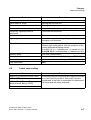
1 Important Information. . . . . . . . . . . . . . . . . . . . . . . . . . . . . . . . . . . . . . . . . . . . . . . . . .
1.1 Safety information . . . . . . . . . . . . . . . . . . . . . . . . . . . . . . . . . . . . . . . . . . . . . . . . . . . .
1.1.1 Safety information: Danger . . . . . . . . . . . . . . . . . . . . . . . . . . . . . . . . . . . . . . . . . .
1.1.2 Safety information: Warning . . . . . . . . . . . . . . . . . . . . . . . . . . . . . . . . . . . . . . . . .
1.1.3 Safety information: Caution . . . . . . . . . . . . . . . . . . . . . . . . . . . . . . . . . . . . . . . . . .
1.1.4 General information. . . . . . . . . . . . . . . . . . . . . . . . . . . . . . . . . . . . . . . . . . . . . . . .
1.1.5 Behaviour in emergencies. . . . . . . . . . . . . . . . . . . . . . . . . . . . . . . . . . . . . . . . . . .
1.1.6 Accident reporting . . . . . . . . . . . . . . . . . . . . . . . . . . . . . . . . . . . . . . . . . . . . . . . . .
1.2 Data protection and data security . . . . . . . . . . . . . . . . . . . . . . . . . . . . . . . . . . . . . . . .
0
1-1
1-1
1-2
1-3
1-4
1-5
1-6
1-6
1-7
2 System data. . . . . . . . . . . . . . . . . . . . . . . . . . . . . . . . . . . . . . . . . . . . . . . . . . . . . . . . . . 2-1
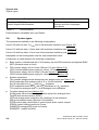
2.1 General system description . . . . . . . . . . . . . . . . . . . . . . . . . . . . . . . . . . . . . . . . . . . . . 2-1
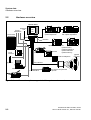
2.2 Hardware overview . . . . . . . . . . . . . . . . . . . . . . . . . . . . . . . . . . . . . . . . . . . . . . . . . . . 2-2
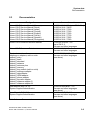
2.3 Documentation. . . . . . . . . . . . . . . . . . . . . . . . . . . . . . . . . . . . . . . . . . . . . . . . . . . . . . . 2-3
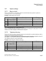
2.4 System types . . . . . . . . . . . . . . . . . . . . . . . . . . . . . . . . . . . . . . . . . . . . . . . . . . . . . . . . 2-4
2.5 Hicom 108 system overview . . . . . . . . . . . . . . . . . . . . . . . . . . . . . . . . . . . . . . . . . . . . 2-5
2.6 Hicom 112 system overview . . . . . . . . . . . . . . . . . . . . . . . . . . . . . . . . . . . . . . . . . . . . 2-6
2.7 Hicom 118 system overview . . . . . . . . . . . . . . . . . . . . . . . . . . . . . . . . . . . . . . . . . . . . 2-7
2.8 Technical data . . . . . . . . . . . . . . . . . . . . . . . . . . . . . . . . . . . . . . . . . . . . . . . . . . . . . . . 2-8
2.9 Basic configuration and system expansions . . . . . . . . . . . . . . . . . . . . . . . . . . . . . . . 2-10
2.10 System interfaces . . . . . . . . . . . . . . . . . . . . . . . . . . . . . . . . . . . . . . . . . . . . . . . . . . 2-10
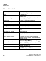
3 Overview of modules . . . . . . . . . . . . . . . . . . . . . . . . . . . . . . . . . . . . . . . . . . . . . . . . . . 3-1
3.1 Table of item code numbers . . . . . . . . . . . . . . . . . . . . . . . . . . . . . . . . . . . . . . . . . . . . 3-1
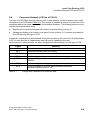
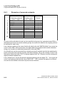
3.2 Overview of configurations . . . . . . . . . . . . . . . . . . . . . . . . . . . . . . . . . . . . . . . . . . . . . 3-5
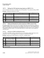
3.3 Standard extension number plans . . . . . . . . . . . . . . . . . . . . . . . . . . . . . . . . . . . . . . . . 3-6
3.3.1 Standard numbering of the MB modules. . . . . . . . . . . . . . . . . . . . . . . . . . . . . . . . 3-6
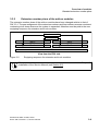
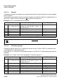
3.3.2 Extension number plans of the add-on modules. . . . . . . . . . . . . . . . . . . . . . . . . . 3-9
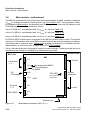
3.4 Main module - motherboard. . . . . . . . . . . . . . . . . . . . . . . . . . . . . . . . . . . . . . . . . . . . 3-10
3.5 Add-on modules for system expansions . . . . . . . . . . . . . . . . . . . . . . . . . . . . . . . . . . 3-13
3.5.1 SLAS8/4 (subscriber line analogue) . . . . . . . . . . . . . . . . . . . . . . . . . . . . . . . . . . 3-15
3.5.2 SLAS16 (subscriber line analogue). . . . . . . . . . . . . . . . . . . . . . . . . . . . . . . . . . . 3-16
3.5.3 SLU8 (subscriber line UP0/E) . . . . . . . . . . . . . . . . . . . . . . . . . . . . . . . . . . . . . . . 3-17
3.5.4 STLS (subscriber trunk line S 0). . . . . . . . . . . . . . . . . . . . . . . . . . . . . . . . . . . . . . 3-18
3.5.5 TLA 4/2 (trunk line analogue) . . . . . . . . . . . . . . . . . . . . . . . . . . . . . . . . . . . . . . . 3-19
3.5.6 TLA 8 (trunk line analogue) . . . . . . . . . . . . . . . . . . . . . . . . . . . . . . . . . . . . . . . . . 3-20
3.6 Function expansions with options bus . . . . . . . . . . . . . . . . . . . . . . . . . . . . . . . . . . . . 3-21
3.6.1 Options adapter. . . . . . . . . . . . . . . . . . . . . . . . . . . . . . . . . . . . . . . . . . . . . . . . . . 3-21
3.6.2 GEE module . . . . . . . . . . . . . . . . . . . . . . . . . . . . . . . . . . . . . . . . . . . . . . . . . . . . 3-21
3.6.3 Serial interface board (SIB) (V.24 connection) . . . . . . . . . . . . . . . . . . . . . . . . . . 3-22
3.6.4 STRB control relay module (actuators/sensors) . . . . . . . . . . . . . . . . . . . . . . . . . 3-23
A31003-K16-X001-3-7620, 07/99
Hicom 100 E Version 2.1, Service manual
0-1
Table of Contents
3.6.5 Fax recognition and DDI module . . . . . . . . . . . . . . . . . . . . . . . . . . . . . . . . . . . . .
3.6.6 ALUM module. . . . . . . . . . . . . . . . . . . . . . . . . . . . . . . . . . . . . . . . . . . . . . . . . . . .
3.6.7 STBG4 module . . . . . . . . . . . . . . . . . . . . . . . . . . . . . . . . . . . . . . . . . . . . . . . . . . .
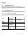
3.7 Function expansions without options bus . . . . . . . . . . . . . . . . . . . . . . . . . . . . . . . . . .
3.7.1 EXM/MPPI . . . . . . . . . . . . . . . . . . . . . . . . . . . . . . . . . . . . . . . . . . . . . . . . . . . . . .
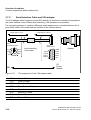
3.7.2 Serial Interface Cable and V.24 adapter . . . . . . . . . . . . . . . . . . . . . . . . . . . . . . .
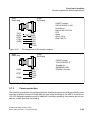
3.7.3 Coarse protection . . . . . . . . . . . . . . . . . . . . . . . . . . . . . . . . . . . . . . . . . . . . . . . . .
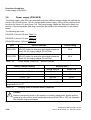
3.8 Power supply (PSU/UPS) . . . . . . . . . . . . . . . . . . . . . . . . . . . . . . . . . . . . . . . . . . . . . .
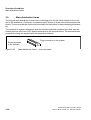
3.9 Main distribution frame . . . . . . . . . . . . . . . . . . . . . . . . . . . . . . . . . . . . . . . . . . . . . . . .
3-25
3-27
3-29
3-30
3-30
3-32
3-33
3-34
3-36
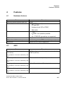
4 Features . . . . . . . . . . . . . . . . . . . . . . . . . . . . . . . . . . . . . . . . . . . . . . . . . . . . . . . . . . . . . 4-1
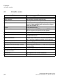
4.1 Hardware features. . . . . . . . . . . . . . . . . . . . . . . . . . . . . . . . . . . . . . . . . . . . . . . . . . . . . 4-1
4.2 ANIS . . . . . . . . . . . . . . . . . . . . . . . . . . . . . . . . . . . . . . . . . . . . . . . . . . . . . . . . . . . . . . . 4-1
4.3 All traffic modes. . . . . . . . . . . . . . . . . . . . . . . . . . . . . . . . . . . . . . . . . . . . . . . . . . . . . . . 4-2
4.4 Incoming traffic, general . . . . . . . . . . . . . . . . . . . . . . . . . . . . . . . . . . . . . . . . . . . . . . . . 4-3
4.5 Outgoing traffic, general (as of SW 2.0.2). . . . . . . . . . . . . . . . . . . . . . . . . . . . . . . . . . . 4-4
4.6 General trunk traffic. . . . . . . . . . . . . . . . . . . . . . . . . . . . . . . . . . . . . . . . . . . . . . . . . . . . 4-5
4.7 Incoming trunk traffic. . . . . . . . . . . . . . . . . . . . . . . . . . . . . . . . . . . . . . . . . . . . . . . . . . . 4-5
4.8 Outgoing trunk traffic. . . . . . . . . . . . . . . . . . . . . . . . . . . . . . . . . . . . . . . . . . . . . . . . . . . 4-6
4.9 Least cost routing . . . . . . . . . . . . . . . . . . . . . . . . . . . . . . . . . . . . . . . . . . . . . . . . . . . . . 4-7
4.10 Internal traffic . . . . . . . . . . . . . . . . . . . . . . . . . . . . . . . . . . . . . . . . . . . . . . . . . . . . . . . 4-8
4.11 Miscellaneous . . . . . . . . . . . . . . . . . . . . . . . . . . . . . . . . . . . . . . . . . . . . . . . . . . . . . . . 4-9
4.12 Call charges - call detail recording . . . . . . . . . . . . . . . . . . . . . . . . . . . . . . . . . . . . . . 4-11
4.13 Configuration. . . . . . . . . . . . . . . . . . . . . . . . . . . . . . . . . . . . . . . . . . . . . . . . . . . . . . . 4-11
4.14 Measures in the event of a power failure . . . . . . . . . . . . . . . . . . . . . . . . . . . . . . . . . 4-12
4.15 Cordless solutions. . . . . . . . . . . . . . . . . . . . . . . . . . . . . . . . . . . . . . . . . . . . . . . . . . . 4-12
4.16 CorNet-N . . . . . . . . . . . . . . . . . . . . . . . . . . . . . . . . . . . . . . . . . . . . . . . . . . . . . . . . . . 4-12
4.17 Q-Sig networking. . . . . . . . . . . . . . . . . . . . . . . . . . . . . . . . . . . . . . . . . . . . . . . . . . . . 4-13
4.18 Euro-ISDN to PBX. . . . . . . . . . . . . . . . . . . . . . . . . . . . . . . . . . . . . . . . . . . . . . . . . . . 4-13
4.19 Euro-ISDN to extension S0 . . . . . . . . . . . . . . . . . . . . . . . . . . . . . . . . . . . . . . . . . . . . 4-14
4.20 Description of feature update in SW 2.1 . . . . . . . . . . . . . . . . . . . . . . . . . . . . . . . . . . 4-15
4.20.1 MSN feature . . . . . . . . . . . . . . . . . . . . . . . . . . . . . . . . . . . . . . . . . . . . . . . . . . . . 4-15
4.20.1.1 Specific seizure with existing DDI number. . . . . . . . . . . . . . . . . . . . . . . . . . 4-15
4.20.1.2 DDI-specific signalling . . . . . . . . . . . . . . . . . . . . . . . . . . . . . . . . . . . . . . . . . 4-16
4.20.1.3 MULAP group . . . . . . . . . . . . . . . . . . . . . . . . . . . . . . . . . . . . . . . . . . . . . . . 4-16
4.20.1.4 Configuration options . . . . . . . . . . . . . . . . . . . . . . . . . . . . . . . . . . . . . . . . . . 4-17
4.20.2 Automatic DTMF switchover after "CONNECT" . . . . . . . . . . . . . . . . . . . . . . . . . 4-17
4.20.3 Enhanced door opener functions . . . . . . . . . . . . . . . . . . . . . . . . . . . . . . . . . . . . 4-17
4.20.4 Extending an undialed line . . . . . . . . . . . . . . . . . . . . . . . . . . . . . . . . . . . . . . . . . 4-18
4.20.5 Group ringing, no answer . . . . . . . . . . . . . . . . . . . . . . . . . . . . . . . . . . . . . . . . . . 4-18
4.20.6 Printout of updated customer data . . . . . . . . . . . . . . . . . . . . . . . . . . . . . . . . . . . 4-18
5 Installation . . . . . . . . . . . . . . . . . . . . . . . . . . . . . . . . . . . . . . . . . . . . . . . . . . . . . . . . . . . 5-1
5.1 Selecting the most suitable location . . . . . . . . . . . . . . . . . . . . . . . . . . . . . . . . . . . . . . . 5-1
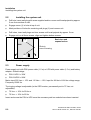
5.2 Installing the system unit. . . . . . . . . . . . . . . . . . . . . . . . . . . . . . . . . . . . . . . . . . . . . . . . 5-2
0-2
A31003-K16-X001-3-7620, 07/99
Hicom 100 E Version 2.1, Service manual
Table of Contents
5.3 Power supply . . . . . . . . . . . . . . . . . . . . . . . . . . . . . . . . . . . . . . . . . . . . . . . . . . . . . . . . 5-2
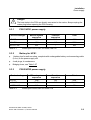
5.3.1 PSU1/UPS1 power supply . . . . . . . . . . . . . . . . . . . . . . . . . . . . . . . . . . . . . . . . . . 5-3
5.3.2 Battery for UPS1 . . . . . . . . . . . . . . . . . . . . . . . . . . . . . . . . . . . . . . . . . . . . . . . . . . 5-3
5.3.3 PSU2/UPS2 power supply . . . . . . . . . . . . . . . . . . . . . . . . . . . . . . . . . . . . . . . . . . 5-3
5.3.4 Battery for UPS2 . . . . . . . . . . . . . . . . . . . . . . . . . . . . . . . . . . . . . . . . . . . . . . . . . . 5-4
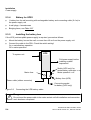
5.3.5 Installing the battery box . . . . . . . . . . . . . . . . . . . . . . . . . . . . . . . . . . . . . . . . . . . . 5-4
5.4 Installing cards for system expansions . . . . . . . . . . . . . . . . . . . . . . . . . . . . . . . . . . . . 5-6
5.4.1 Installing or replacing an SLU8 . . . . . . . . . . . . . . . . . . . . . . . . . . . . . . . . . . . . . . . 5-6
5.5 Extension and line number allocation . . . . . . . . . . . . . . . . . . . . . . . . . . . . . . . . . . . . . 5-6
5.6 Connecting ISDN (S0) interfaces . . . . . . . . . . . . . . . . . . . . . . . . . . . . . . . . . . . . . . . . . 5-8
5.7 Connecting to ISDN trunk . . . . . . . . . . . . . . . . . . . . . . . . . . . . . . . . . . . . . . . . . . . . . . 5-8
5.8 Connecting to Hicom 300 (CorNet-N) . . . . . . . . . . . . . . . . . . . . . . . . . . . . . . . . . . . . . 5-8
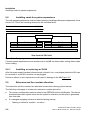
5.9 Connecting ISDN terminals . . . . . . . . . . . . . . . . . . . . . . . . . . . . . . . . . . . . . . . . . . . . . 5-9
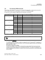
5.10 Extension number for internal S0 extensions. . . . . . . . . . . . . . . . . . . . . . . . . . . . . . 5-12
5.11 Multi-device connection . . . . . . . . . . . . . . . . . . . . . . . . . . . . . . . . . . . . . . . . . . . . . . 5-12
5.11.1 Call forwarding in the exchange in the case of PMP. . . . . . . . . . . . . . . . . . . . . 5-12
5.12 Connecting printer, modem or PC . . . . . . . . . . . . . . . . . . . . . . . . . . . . . . . . . . . . . . 5-13
5.12.1 Pin assignment of the V.24 adapter cable. . . . . . . . . . . . . . . . . . . . . . . . . . . . . 5-15
5.12.1.1 V.24 connection to MB . . . . . . . . . . . . . . . . . . . . . . . . . . . . . . . . . . . . . . . . 5-15
5.12.1.2 V.24 connection to SIB . . . . . . . . . . . . . . . . . . . . . . . . . . . . . . . . . . . . . . . . 5-16
5.12.2 Pin assignment of the printer/modem adapter . . . . . . . . . . . . . . . . . . . . . . . . . 5-16
5.13 Connecting a/b terminals or entrance telephones . . . . . . . . . . . . . . . . . . . . . . . . . . 5-18
5.14 Connecting automatic dialler (associated dial) . . . . . . . . . . . . . . . . . . . . . . . . . . . . 5-19
5.15 Connecting the fax DDI module . . . . . . . . . . . . . . . . . . . . . . . . . . . . . . . . . . . . . . . . 5-19
6 Initial operation . . . . . . . . . . . . . . . . . . . . . . . . . . . . . . . . . . . . . . . . . . . . . . . . . . . . . . . 6-1
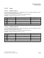
6.1 Cutover . . . . . . . . . . . . . . . . . . . . . . . . . . . . . . . . . . . . . . . . . . . . . . . . . . . . . . . . . . . . 6-1
6.2 Upgrading a system . . . . . . . . . . . . . . . . . . . . . . . . . . . . . . . . . . . . . . . . . . . . . . . . . . . 6-1
6.3 Nationalisation . . . . . . . . . . . . . . . . . . . . . . . . . . . . . . . . . . . . . . . . . . . . . . . . . . . . . . . 6-2
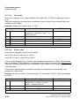
6.4 Re-initialising . . . . . . . . . . . . . . . . . . . . . . . . . . . . . . . . . . . . . . . . . . . . . . . . . . . . . . . . 6-3
6.4.1 Re-initialising the system cards (as of SW 2.0.1+) . . . . . . . . . . . . . . . . . . . . . . . . 6-3
6.4.2 Re-initialising the expansions modules (as of SW 2.0.2) . . . . . . . . . . . . . . . . . . . 6-3
6.5 Customer data . . . . . . . . . . . . . . . . . . . . . . . . . . . . . . . . . . . . . . . . . . . . . . . . . . . . . . . 6-4
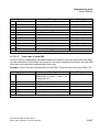
6.6 Terminal test . . . . . . . . . . . . . . . . . . . . . . . . . . . . . . . . . . . . . . . . . . . . . . . . . . . . . . . . 6-4
6.7 Extension numbering plan, two-box system (118-2) . . . . . . . . . . . . . . . . . . . . . . . . . . 6-4
6.8 System extension number . . . . . . . . . . . . . . . . . . . . . . . . . . . . . . . . . . . . . . . . . . . . . . 6-5
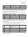
6.9 Call management (CM) . . . . . . . . . . . . . . . . . . . . . . . . . . . . . . . . . . . . . . . . . . . . . . . . 6-6
6.9.1 Call allocation . . . . . . . . . . . . . . . . . . . . . . . . . . . . . . . . . . . . . . . . . . . . . . . . . . . . 6-6
6.9.2 Reference to call destination lists . . . . . . . . . . . . . . . . . . . . . . . . . . . . . . . . . . . . . 6-6
6.9.3 Call destination lists. . . . . . . . . . . . . . . . . . . . . . . . . . . . . . . . . . . . . . . . . . . . . . . . 6-6
6.9.4 Call group and hunt groups . . . . . . . . . . . . . . . . . . . . . . . . . . . . . . . . . . . . . . . . . . 6-7
6.9.5 Call allocation/call management: examples . . . . . . . . . . . . . . . . . . . . . . . . . . . . . 6-8
6.10 Networking (Hicom 112/118 only) . . . . . . . . . . . . . . . . . . . . . . . . . . . . . . . . . . . . . . 6-15
6.10.1 Automatic line seizure (menu 16 11) for optiset telephones only . . . . . . . . . . . 6-15
6.10.2 Route assignment (menu 16 12) . . . . . . . . . . . . . . . . . . . . . . . . . . . . . . . . . . . . 6-15
A31003-K16-X001-3-7620, 07/99
Hicom 100 E Version 2.1, Service manual
0-3
Table of Contents
6.10.3 Overflow route (menu 16 13) . . . . . . . . . . . . . . . . . . . . . . . . . . . . . . . . . . . . . . .
6.10.4 Trunk/PBX line type (menu 16 14) . . . . . . . . . . . . . . . . . . . . . . . . . . . . . . . . . . .
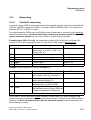
6.10.5 Route names (menu 16 15) . . . . . . . . . . . . . . . . . . . . . . . . . . . . . . . . . . . . . . . .
6.10.6 Route codes (menu7 22 4) . . . . . . . . . . . . . . . . . . . . . . . . . . . . . . . . . . . . . . . . .
6.10.7 Digit repetition (menu 16 16) . . . . . . . . . . . . . . . . . . . . . . . . . . . . . . . . . . . . . . .
6.10.8 Route seizure (menu 16 17) . . . . . . . . . . . . . . . . . . . . . . . . . . . . . . . . . . . . . . . .
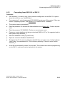
6.10.9 Error messages for network settings . . . . . . . . . . . . . . . . . . . . . . . . . . . . . . . . .
6.11 Upgrading a system . . . . . . . . . . . . . . . . . . . . . . . . . . . . . . . . . . . . . . . . . . . . . . . . .
6.12 Converting from SW 2.0.2 to SW 2.1 . . . . . . . . . . . . . . . . . . . . . . . . . . . . . . . . . . . .
6-15
6-15
6-15
6-15
6-16
6-16
6-16
6-20
6-21
7 Administration and maintenance . . . . . . . . . . . . . . . . . . . . . . . . . . . . . . . . . . . . . . . . . 7-1
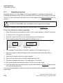
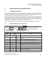
7.1 Configuring the system . . . . . . . . . . . . . . . . . . . . . . . . . . . . . . . . . . . . . . . . . . . . . . . . . 7-1
7.2 Functions without an access code . . . . . . . . . . . . . . . . . . . . . . . . . . . . . . . . . . . . . . . . 7-1
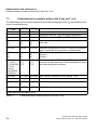
7.3 Codes/extension numbers without the S key and * or # . . . . . . . . . . . . . . . . . . . . . . . . 7-2
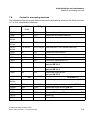
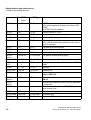
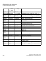
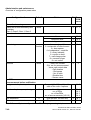
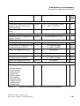
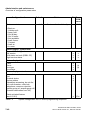
7.4 Codes for accessing services . . . . . . . . . . . . . . . . . . . . . . . . . . . . . . . . . . . . . . . . . . . . 7-3
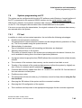
7.5 System programming in interactive mode. . . . . . . . . . . . . . . . . . . . . . . . . . . . . . . . . . . 7-7
7.6 System programming in expert mode . . . . . . . . . . . . . . . . . . . . . . . . . . . . . . . . . . . . . . 7-8
7.6.1 Starting system administration . . . . . . . . . . . . . . . . . . . . . . . . . . . . . . . . . . . . . . . . 7-9
7.6.2 Codes for expert mode . . . . . . . . . . . . . . . . . . . . . . . . . . . . . . . . . . . . . . . . . . . . . . 7-9
7.7 Overview of configuration parameters . . . . . . . . . . . . . . . . . . . . . . . . . . . . . . . . . . . . 7-30
7.8 System programming via PC . . . . . . . . . . . . . . . . . . . . . . . . . . . . . . . . . . . . . . . . . . . 7-43
7.8.1 PC tool . . . . . . . . . . . . . . . . . . . . . . . . . . . . . . . . . . . . . . . . . . . . . . . . . . . . . . . . . 7-43
7.9 Teleservice . . . . . . . . . . . . . . . . . . . . . . . . . . . . . . . . . . . . . . . . . . . . . . . . . . . . . . . . . 7-44
7.9.1 Modem transfer . . . . . . . . . . . . . . . . . . . . . . . . . . . . . . . . . . . . . . . . . . . . . . . . . . 7-44
7.9.2 Digital modem (Menu 30 2) . . . . . . . . . . . . . . . . . . . . . . . . . . . . . . . . . . . . . . . . . 7-45
7.9.3 DTMF remote administration and maintenance . . . . . . . . . . . . . . . . . . . . . . . . . . 7-45
7.9.3.1 DTMF remote administration and maintenance procedure . . . . . . . . . . . . . . 7-46
7.9.3.2 Activating DTMF remote administration. . . . . . . . . . . . . . . . . . . . . . . . . . . . . 7-47
7.10 Classes of service . . . . . . . . . . . . . . . . . . . . . . . . . . . . . . . . . . . . . . . . . . . . . . . . . . . 7-48
7.11 Toll restriction . . . . . . . . . . . . . . . . . . . . . . . . . . . . . . . . . . . . . . . . . . . . . . . . . . . . . . 7-50
7.11.1 Procedure for satellite PBXs. . . . . . . . . . . . . . . . . . . . . . . . . . . . . . . . . . . . . . . . 7-50
7.11.2 Toll restriction data . . . . . . . . . . . . . . . . . . . . . . . . . . . . . . . . . . . . . . . . . . . . . . . 7-50
7.12 Timer . . . . . . . . . . . . . . . . . . . . . . . . . . . . . . . . . . . . . . . . . . . . . . . . . . . . . . . . . . . . . 7-51
8 Least Cost Routing (LCR) . . . . . . . . . . . . . . . . . . . . . . . . . . . . . . . . . . . . . . . . . . . . . . . 8-1
8.1 Single-stage LCR . . . . . . . . . . . . . . . . . . . . . . . . . . . . . . . . . . . . . . . . . . . . . . . . . . . . . 8-3
8.2 Two-stage LCR . . . . . . . . . . . . . . . . . . . . . . . . . . . . . . . . . . . . . . . . . . . . . . . . . . . . . . . 8-4
8.3 Dial-in procedure (previously T-Net) as of V2.1 . . . . . . . . . . . . . . . . . . . . . . . . . . . . . . 8-5
8.3.1 Background/General. . . . . . . . . . . . . . . . . . . . . . . . . . . . . . . . . . . . . . . . . . . . . . . . 8-5
8.3.2 Implementation with Hicom 100 E . . . . . . . . . . . . . . . . . . . . . . . . . . . . . . . . . . . . . 8-5
8.3.3 Dialling into the CN. . . . . . . . . . . . . . . . . . . . . . . . . . . . . . . . . . . . . . . . . . . . . . . . . 8-6
8.3.3.1 Signalling method . . . . . . . . . . . . . . . . . . . . . . . . . . . . . . . . . . . . . . . . . . . . . . 8-6
8.3.4 Remote maintenance of LCR functions . . . . . . . . . . . . . . . . . . . . . . . . . . . . . . . . . 8-7
8.3.5 Parameters for the dial-in procedure . . . . . . . . . . . . . . . . . . . . . . . . . . . . . . . . . . . 8-7
8.4 Corporate Network LCR (as of V2.0.2) . . . . . . . . . . . . . . . . . . . . . . . . . . . . . . . . . . . . . 8-9
0-4
A31003-K16-X001-3-7620, 07/99
Hicom 100 E Version 2.1, Service manual
Table of Contents
8.4.1 Examples of corporate networks . . . . . . . . . . . . . . . . . . . . . . . . . . . . . . . . . . . . . 8-10
9 Maintenance and repair . . . . . . . . . . . . . . . . . . . . . . . . . . . . . . . . . . . . . . . . . . . . . . . .
9.1 Maintenance . . . . . . . . . . . . . . . . . . . . . . . . . . . . . . . . . . . . . . . . . . . . . . . . . . . . . . . .
9.2 Repair . . . . . . . . . . . . . . . . . . . . . . . . . . . . . . . . . . . . . . . . . . . . . . . . . . . . . . . . . . . . .
9.3 Spare parts . . . . . . . . . . . . . . . . . . . . . . . . . . . . . . . . . . . . . . . . . . . . . . . . . . . . . . . . .
9-1
9-1
9-1
9-1
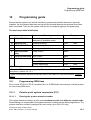
10 Programming guide . . . . . . . . . . . . . . . . . . . . . . . . . . . . . . . . . . . . . . . . . . . . . . . . . 10-1
10.1 Programming ISDN lines . . . . . . . . . . . . . . . . . . . . . . . . . . . . . . . . . . . . . . . . . . . . . 10-1
10.1.1 Point-to-point system connection (P P) . . . . . . . . . . . . . . . . . . . . . . . . . . . . . . . 10-1
10.1.1.1 Entering the system extension number . . . . . . . . . . . . . . . . . . . . . . . . . . . 10-1
10.1.1.2 Changing port configuration . . . . . . . . . . . . . . . . . . . . . . . . . . . . . . . . . . . . 10-2
10.1.1.3 Activating call number suppression . . . . . . . . . . . . . . . . . . . . . . . . . . . . . . 10-3
10.1.2 ISDN multi-device connection (point-to-multipoint) . . . . . . . . . . . . . . . . . . . . . . 10-3
10.1.2.1 Entering MSN . . . . . . . . . . . . . . . . . . . . . . . . . . . . . . . . . . . . . . . . . . . . . . . 10-3
10.1.2.2 Programming an ISDN port as a multi-device connection . . . . . . . . . . . . . 10-3
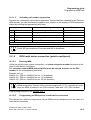
10.2 Analogue trunk. . . . . . . . . . . . . . . . . . . . . . . . . . . . . . . . . . . . . . . . . . . . . . . . . . . . . 10-4
10.2.1 Setting analogue signalling method . . . . . . . . . . . . . . . . . . . . . . . . . . . . . . . . . 10-4
10.2.2 Setting a dial pause. . . . . . . . . . . . . . . . . . . . . . . . . . . . . . . . . . . . . . . . . . . . . . 10-5
10.2.3 Changing a trunk call interval . . . . . . . . . . . . . . . . . . . . . . . . . . . . . . . . . . . . . . 10-5
10.2.4 Changing line length . . . . . . . . . . . . . . . . . . . . . . . . . . . . . . . . . . . . . . . . . . . . . 10-6
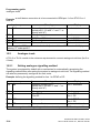
10.3 Networking . . . . . . . . . . . . . . . . . . . . . . . . . . . . . . . . . . . . . . . . . . . . . . . . . . . . . . . . 10-7
10.3.1 CorNet-N networking. . . . . . . . . . . . . . . . . . . . . . . . . . . . . . . . . . . . . . . . . . . . . 10-7
10.3.2 Rerouting. . . . . . . . . . . . . . . . . . . . . . . . . . . . . . . . . . . . . . . . . . . . . . . . . . . . . . 10-8
10.3.2.1 Active rerouting. . . . . . . . . . . . . . . . . . . . . . . . . . . . . . . . . . . . . . . . . . . . . . 10-8
10.3.2.2 Changing a route . . . . . . . . . . . . . . . . . . . . . . . . . . . . . . . . . . . . . . . . . . . . 10-9
10.3.3 Analogue networking. . . . . . . . . . . . . . . . . . . . . . . . . . . . . . . . . . . . . . . . . . . . . 10-9
10.3.3.1 Connection as master. . . . . . . . . . . . . . . . . . . . . . . . . . . . . . . . . . . . . . . . . 10-9
10.3.3.2 Connection as slave . . . . . . . . . . . . . . . . . . . . . . . . . . . . . . . . . . . . . . . . . 10-10
10.3.4 Automatic line seizure (Simplified dialling) . . . . . . . . . . . . . . . . . . . . . . . . . . . 10-10
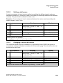
10.3.5 Route assignment . . . . . . . . . . . . . . . . . . . . . . . . . . . . . . . . . . . . . . . . . . . . . . 10-11
10.3.6 Route type . . . . . . . . . . . . . . . . . . . . . . . . . . . . . . . . . . . . . . . . . . . . . . . . . . . . 10-12
10.3.7 Route overflow . . . . . . . . . . . . . . . . . . . . . . . . . . . . . . . . . . . . . . . . . . . . . . . . 10-13
10.3.8 Digit repetition . . . . . . . . . . . . . . . . . . . . . . . . . . . . . . . . . . . . . . . . . . . . . . . . . 10-13
10.3.9 Route seizure . . . . . . . . . . . . . . . . . . . . . . . . . . . . . . . . . . . . . . . . . . . . . . . . . 10-14
10.3.10 Route names . . . . . . . . . . . . . . . . . . . . . . . . . . . . . . . . . . . . . . . . . . . . . . . . . 10-15
10.4 Programming extensions . . . . . . . . . . . . . . . . . . . . . . . . . . . . . . . . . . . . . . . . . . . . 10-16
10.4.1 Station types . . . . . . . . . . . . . . . . . . . . . . . . . . . . . . . . . . . . . . . . . . . . . . . . . . 10-16
10.4.1.1 Stations connected to the Up0/E port. . . . . . . . . . . . . . . . . . . . . . . . . . . . . 10-16
10.4.1.2 Stations connected to the a/b port . . . . . . . . . . . . . . . . . . . . . . . . . . . . . . 10-16
10.4.1.3 Stations connected to the S0 bus. . . . . . . . . . . . . . . . . . . . . . . . . . . . . . . 10-17
10.5 Station attributes . . . . . . . . . . . . . . . . . . . . . . . . . . . . . . . . . . . . . . . . . . . . . . . . . . 10-18
10.5.1 Individual classes of service . . . . . . . . . . . . . . . . . . . . . . . . . . . . . . . . . . . . . . 10-18
10.5.1.1 Intrusion . . . . . . . . . . . . . . . . . . . . . . . . . . . . . . . . . . . . . . . . . . . . . . . . . . 10-18
10.5.1.2 Associated dialling . . . . . . . . . . . . . . . . . . . . . . . . . . . . . . . . . . . . . . . . . . 10-18
A31003-K16-X001-3-7620, 07/99
Hicom 100 E Version 2.1, Service manual
0-5
Table of Contents
10.5.1.3 Camp-on rejection (Data security/Call waiting) . . . . . . . . . . . . . . . . . . . . .
10.5.1.4 Overriding do-not-disturb . . . . . . . . . . . . . . . . . . . . . . . . . . . . . . . . . . . . . .
10.5.1.5 Headset . . . . . . . . . . . . . . . . . . . . . . . . . . . . . . . . . . . . . . . . . . . . . . . . . . .
10.5.1.6 Call pickup groups . . . . . . . . . . . . . . . . . . . . . . . . . . . . . . . . . . . . . . . . . . .
10.5.1.7 Resetting active individual code lock . . . . . . . . . . . . . . . . . . . . . . . . . . . . .
10.5.1.8 Caller list (as of SW version 2.0.2). . . . . . . . . . . . . . . . . . . . . . . . . . . . . . .
10.5.1.9 Call trace (as of SW version 2.0.2) . . . . . . . . . . . . . . . . . . . . . . . . . . . . . .
10.5.1.10 Diversion, external (as of SW version 2.0.2) . . . . . . . . . . . . . . . . . . . . . .
10.5.1.11 Setting up executive-secretary groups. . . . . . . . . . . . . . . . . . . . . . . . . . .
10.5.1.12 Station names . . . . . . . . . . . . . . . . . . . . . . . . . . . . . . . . . . . . . . . . . . . . .
10.5.2 Doorphone setup . . . . . . . . . . . . . . . . . . . . . . . . . . . . . . . . . . . . . . . . . . . . . . .
10.5.2.1 Setting up an entrance telephone (up to SW 2.0.1+). . . . . . . . . . . . . . . . .
10.5.2.2 Setting up the entrance telephones (as of SW version 2.0.2) . . . . . . . . . .
10.5.2.3 Programming the receiving extension for the doorbell
(up to SW 2.0.1+) . . . . . . . . . . . . . . . . . . . . . . . . . . . . . . . . . . . . . . . . . . . .
10.5.2.4 Programming a receiving extension for the doorbell
(as of SW version 2.0.2) . . . . . . . . . . . . . . . . . . . . . . . . . . . . . . . . . . . . . . .
10.5.3 Setting up the door opener . . . . . . . . . . . . . . . . . . . . . . . . . . . . . . . . . . . . . . . .
10.5.3.1 Controlling the door opener with actuators . . . . . . . . . . . . . . . . . . . . . . . .
10.5.3.2 Controlling the door opener with a door opener adapter
(up to SW version 2.0.1+) . . . . . . . . . . . . . . . . . . . . . . . . . . . . . . . . . . . . . .
10.5.3.3 Controlling the door opener via a door opener adapter
(as of SW version 2.0.2) . . . . . . . . . . . . . . . . . . . . . . . . . . . . . . . . . . . . . . .
10.5.3.4 Diverting calls to receiving extension for the doorbell
(as of SW version 2.0.2) . . . . . . . . . . . . . . . . . . . . . . . . . . . . . . . . . . . . . . .
10.5.3.5 DTMF release class of service. . . . . . . . . . . . . . . . . . . . . . . . . . . . . . . . . .
10.5.4 Trunk access . . . . . . . . . . . . . . . . . . . . . . . . . . . . . . . . . . . . . . . . . . . . . . . . . .
10.5.4.1 Classes of service up to SW version 2.0.1+ . . . . . . . . . . . . . . . . . . . . . . .
10.5.4.2 Classes of service as of SW version 2.0.2. . . . . . . . . . . . . . . . . . . . . . . . .
10.5.4.3 Allowed numbers list up to SW version 2.0.1+ . . . . . . . . . . . . . . . . . . . . .
10.5.4.4 Allowed numbers list as of SW version 2.0.2. . . . . . . . . . . . . . . . . . . . . . .
10.5.4.5 Barred numbers list up to SW version 2.0.1+ . . . . . . . . . . . . . . . . . . . . . .
10.5.4.6 Barred numbers list as of SW version 2.0.2. . . . . . . . . . . . . . . . . . . . . . . .
10.5.4.7 Trunk access, day, up to SW version 2.0.1+ . . . . . . . . . . . . . . . . . . . . . . .
10.5.4.8 Trunk access, day, as of SW version 2.0.2 . . . . . . . . . . . . . . . . . . . . . . . .
10.5.4.9 Reference extensions . . . . . . . . . . . . . . . . . . . . . . . . . . . . . . . . . . . . . . . .
10.5.4.10 Normal extensions . . . . . . . . . . . . . . . . . . . . . . . . . . . . . . . . . . . . . . . . . .
10.5.4.11 Trunk access, night, up to SW version 2.0.1+ . . . . . . . . . . . . . . . . . . . . .
10.5.4.12 Trunk access, night, up to SW version 2.0.2 . . . . . . . . . . . . . . . . . . . . . .
10.5.4.13 Reference extensions . . . . . . . . . . . . . . . . . . . . . . . . . . . . . . . . . . . . . . .
10.5.4.14 Normal extensions . . . . . . . . . . . . . . . . . . . . . . . . . . . . . . . . . . . . . . . . . .
10.5.4.15 Trunk access with active code lock (as of SW version 2.0.2) . . . . . . . . .
10.5.4.16 Dialling signal transmission mode (as of SW version 2.0.2) . . . . . . . . . .
10.6.1 DDI numbers . . . . . . . . . . . . . . . . . . . . . . . . . . . . . . . . . . . . . . . . . . . . . . . . . .
0-6
10-19
10-19
10-20
10-20
10-21
10-22
10-22
10-23
10-23
10-24
10-24
10-24
10-25
10-26
10-26
10-27
10-27
10-27
10-28
10-28
10-29
10-30
10-30
10-30
10-30
10-31
10-32
10-32
10-33
10-33
10-34
10-35
10-35
10-35
10-36
10-37
10-37
10-38
10-39
A31003-K16-X001-3-7620, 07/99
Hicom 100 E Version 2.1, Service manual
Table of Contents
10.6.2 Call groups . . . . . . . . . . . . . . . . . . . . . . . . . . . . . . . . . . . . . . . . . . . . . . . . . . .
10.6.2.1 Group members . . . . . . . . . . . . . . . . . . . . . . . . . . . . . . . . . . . . . . . . . . . .
10.6.2.2 Group ringing mode . . . . . . . . . . . . . . . . . . . . . . . . . . . . . . . . . . . . . . . . .
10.6.2.3 Group names . . . . . . . . . . . . . . . . . . . . . . . . . . . . . . . . . . . . . . . . . . . . . .
10.6.2.4 Signalling type . . . . . . . . . . . . . . . . . . . . . . . . . . . . . . . . . . . . . . . . . . . . .
10.6.3 Call allocation with ISDN DDI . . . . . . . . . . . . . . . . . . . . . . . . . . . . . . . . . . . . .
10.6.4 Reference to call destination lists . . . . . . . . . . . . . . . . . . . . . . . . . . . . . . . . . .
10.6.4.1 Reference for day . . . . . . . . . . . . . . . . . . . . . . . . . . . . . . . . . . . . . . . . . . .
10.6.4.2 Reference for night . . . . . . . . . . . . . . . . . . . . . . . . . . . . . . . . . . . . . . . . . .
10.6.5 Call allocation for incoming analogue trunk calls . . . . . . . . . . . . . . . . . . . . . .
10.6.5.1 Changing the analogue destination extension during the day . . . . . . . . .
10.6.5.2 Changing analogue destination extensions at night . . . . . . . . . . . . . . . . .
10.6.6 Call allocation for internal calls . . . . . . . . . . . . . . . . . . . . . . . . . . . . . . . . . . . .
10.6.7 Call destination lists. . . . . . . . . . . . . . . . . . . . . . . . . . . . . . . . . . . . . . . . . . . . .
10.6.7.1 Destination indexes . . . . . . . . . . . . . . . . . . . . . . . . . . . . . . . . . . . . . . . . .
10.6.7.2 Call forwarding times . . . . . . . . . . . . . . . . . . . . . . . . . . . . . . . . . . . . . . . .
10.6.7.3 Common ringer . . . . . . . . . . . . . . . . . . . . . . . . . . . . . . . . . . . . . . . . . . . . .
10.6.7.4 Setting the common ringer mode . . . . . . . . . . . . . . . . . . . . . . . . . . . . . . .
10.6.8 ISDN DDI settings . . . . . . . . . . . . . . . . . . . . . . . . . . . . . . . . . . . . . . . . . . . . . .
10.6.8.1 Intercept console during the day . . . . . . . . . . . . . . . . . . . . . . . . . . . . . . .
10.6.8.2 Intercept console at night . . . . . . . . . . . . . . . . . . . . . . . . . . . . . . . . . . . . .
10.6.8.3 Defining the console code . . . . . . . . . . . . . . . . . . . . . . . . . . . . . . . . . . . .
10.6.9 Defining intercept criteria. . . . . . . . . . . . . . . . . . . . . . . . . . . . . . . . . . . . . . . . .
10.6.9.1 Defining intercept, no answer . . . . . . . . . . . . . . . . . . . . . . . . . . . . . . . . . .
10.6.9.2 Defining intercept, busy . . . . . . . . . . . . . . . . . . . . . . . . . . . . . . . . . . . . . .
10.6.9.3 Defining intercept, unavailable DDI number . . . . . . . . . . . . . . . . . . . . . . .
10.6.9.4 Defining intercept, incomplete DDI number . . . . . . . . . . . . . . . . . . . . . . .
10.6.9.5 Defining intercept, recall (as of SW version 2.0.2) . . . . . . . . . . . . . . . . . .
10.7 System settings . . . . . . . . . . . . . . . . . . . . . . . . . . . . . . . . . . . . . . . . . . . . . . . . . . .
10.7.1 Music on hold . . . . . . . . . . . . . . . . . . . . . . . . . . . . . . . . . . . . . . . . . . . . . . . . .
10.7.2 Telephone directory . . . . . . . . . . . . . . . . . . . . . . . . . . . . . . . . . . . . . . . . . . . .
10.7.3 Setting the V.24 interface baud rate (as of SW 2.0.1+). . . . . . . . . . . . . . . . . .
10.7.4 V.24 port allocation for data output (as of SW version 2.0.2) . . . . . . . . . . . . .
10.7.4.1 V.24 port for CDRC (Call Detail Recorder) . . . . . . . . . . . . . . . . . . . . . . . .
10.7.4.2 V.24 port for call charges/extension . . . . . . . . . . . . . . . . . . . . . . . . . . . . .
10.7.4.3 V.24 port for call charges/line . . . . . . . . . . . . . . . . . . . . . . . . . . . . . . . . . .
10.7.4.4 V.24 port for customer data printout . . . . . . . . . . . . . . . . . . . . . . . . . . . . .
10.7.4.5 V.24 port for call information. . . . . . . . . . . . . . . . . . . . . . . . . . . . . . . . . . .
10.7.5 External diversion (as of SW 2.0.1+). . . . . . . . . . . . . . . . . . . . . . . . . . . . . . . .
10.7.6 Call forwarding in the case of external diversion (as of SW version 2.0.2) . . .
10.7.7 Caller list display mode (as of SW version 2.0.2) . . . . . . . . . . . . . . . . . . . . . .
10.7.8 Automatic line reservation (as of SW version 2.0.2) . . . . . . . . . . . . . . . . . . . .
10.7.9 Alerting tone during conference (as of SW version 2.0.2). . . . . . . . . . . . . . . .
10.7.10 Alerting tone and ring in call pickup groups. . . . . . . . . . . . . . . . . . . . . . . . . .
A31003-K16-X001-3-7620, 07/99
Hicom 100 E Version 2.1, Service manual
10-39
10-39
10-40
10-41
10-42
10-42
10-42
10-42
10-43
10-44
10-44
10-45
10-45
10-46
10-47
10-48
10-49
10-49
10-51
10-51
10-52
10-54
10-54
10-54
10-55
10-55
10-56
10-56
10-57
10-57
10-57
10-58
10-58
10-58
10-59
10-59
10-60
10-60
10-61
10-61
10-62
10-62
10-63
10-63
0-7
Table of Contents
10.7.11 Signal key mode (as of SW version 2.0.2) . . . . . . . . . . . . . . . . . . . . . . . . . . . 10-64
10.7.12 Night service (as of SW version 2.0.2) . . . . . . . . . . . . . . . . . . . . . . . . . . . . . . 10-64
10.7.13 Codes . . . . . . . . . . . . . . . . . . . . . . . . . . . . . . . . . . . . . . . . . . . . . . . . . . . . . . . 10-65
10.7.13.1 Substitute code for *. . . . . . . . . . . . . . . . . . . . . . . . . . . . . . . . . . . . . . . . . 10-65
10.7.13.2 Substitute code for # . . . . . . . . . . . . . . . . . . . . . . . . . . . . . . . . . . . . . . . . 10-65
10.7.13.3 Line codes . . . . . . . . . . . . . . . . . . . . . . . . . . . . . . . . . . . . . . . . . . . . . . . . 10-66
10.7.13.4 Route codes. . . . . . . . . . . . . . . . . . . . . . . . . . . . . . . . . . . . . . . . . . . . . . . 10-66
10.7.13.5 Trunk code of main PBX . . . . . . . . . . . . . . . . . . . . . . . . . . . . . . . . . . . . . 10-67
10.7.14 Displays . . . . . . . . . . . . . . . . . . . . . . . . . . . . . . . . . . . . . . . . . . . . . . . . . . . . . 10-68
10.7.14.1 Changing message texts . . . . . . . . . . . . . . . . . . . . . . . . . . . . . . . . . . . . . 10-68
10.7.14.2 Changing absence messages . . . . . . . . . . . . . . . . . . . . . . . . . . . . . . . . . 10-68
10.7.14.3 Changing the display language throughout the system
(up to SW 2.0.1+) . . . . . . . . . . . . . . . . . . . . . . . . . . . . . . . . . . . . . . . . . . . . 10-69
10.7.14.4 Changing the display language for each extension
(as of SW version 2.0.2) . . . . . . . . . . . . . . . . . . . . . . . . . . . . . . . . . . . . . . . 10-69
10.7.14.5 Displaying the call duration . . . . . . . . . . . . . . . . . . . . . . . . . . . . . . . . . . . 10-70
10.7.14.6 Name display (as of SW version 2.0.2) . . . . . . . . . . . . . . . . . . . . . . . . . . 10-70
10.7.14.7 Display during recall (as of SW version 2.0.2) . . . . . . . . . . . . . . . . . . . . . 10-70
10.7.14.8 Transfer without notification display (as of SW version 2.0.2) . . . . . . . . . 10-71
10.7.14.9 Data compression/extension (as of SW version 2.0.2) . . . . . . . . . . . . . . 10-72
10.7.15 Call detail recording . . . . . . . . . . . . . . . . . . . . . . . . . . . . . . . . . . . . . . . . . . . . 10-72
10.7.15.1 Changing the data record output format . . . . . . . . . . . . . . . . . . . . . . . . . 10-72
10.7.15.2 Digit suppression . . . . . . . . . . . . . . . . . . . . . . . . . . . . . . . . . . . . . . . . . . . 10-73
10.7.15.3 Recording incoming calls . . . . . . . . . . . . . . . . . . . . . . . . . . . . . . . . . . . . . 10-73
10.7.15.4 Recording the call duration . . . . . . . . . . . . . . . . . . . . . . . . . . . . . . . . . . . 10-74
10.7.15.5 Output on ringing . . . . . . . . . . . . . . . . . . . . . . . . . . . . . . . . . . . . . . . . . . . 10-74
10.7.15.6 Changing the charge factor . . . . . . . . . . . . . . . . . . . . . . . . . . . . . . . . . . . 10-74
10.7.15.7 Changing the currency unit . . . . . . . . . . . . . . . . . . . . . . . . . . . . . . . . . . . 10-75
10.7.15.8 Changing the ISDN factor (as of SW version 2.0.2) . . . . . . . . . . . . . . . . 10-75
10.8 Programming expansion modules. . . . . . . . . . . . . . . . . . . . . . . . . . . . . . . . . . . . . . 10-76
10.8.1 Programming actuators . . . . . . . . . . . . . . . . . . . . . . . . . . . . . . . . . . . . . . . . . . 10-76
10.8.1.1 Defining the actuator type . . . . . . . . . . . . . . . . . . . . . . . . . . . . . . . . . . . . . 10-76
10.8.1.2 Defining actuator response time . . . . . . . . . . . . . . . . . . . . . . . . . . . . . . . . 10-76
10.8.1.3 Allocating extensions and actuators . . . . . . . . . . . . . . . . . . . . . . . . . . . . . 10-77
10.8.1.4 Assigning actuator names . . . . . . . . . . . . . . . . . . . . . . . . . . . . . . . . . . . . . 10-78
10.8.2 Programming sensors . . . . . . . . . . . . . . . . . . . . . . . . . . . . . . . . . . . . . . . . . . . 10-78
10.8.2.1 Defining the destination number . . . . . . . . . . . . . . . . . . . . . . . . . . . . . . . . 10-78
10.8.2.2 Defining the number for recorded announcement device . . . . . . . . . . . . . 10-79
10.8.2.3 Defining voice mail control data . . . . . . . . . . . . . . . . . . . . . . . . . . . . . . . . . 10-79
10.8.2.4 Defining the call duration . . . . . . . . . . . . . . . . . . . . . . . . . . . . . . . . . . . . . . 10-80
10.8.2.5 Defining the number of calls . . . . . . . . . . . . . . . . . . . . . . . . . . . . . . . . . . . 10-80
10.8.2.6 Defining the call interval. . . . . . . . . . . . . . . . . . . . . . . . . . . . . . . . . . . . . . . 10-81
10.8.2.7 Defining the disable time . . . . . . . . . . . . . . . . . . . . . . . . . . . . . . . . . . . . . . 10-81
10.8.2.8 Assigning sensor names . . . . . . . . . . . . . . . . . . . . . . . . . . . . . . . . . . . . . . 10-82
0-8
A31003-K16-X001-3-7620, 07/99
Hicom 100 E Version 2.1, Service manual
Table of Contents
10.8.3 Programming the fax/DDI module . . . . . . . . . . . . . . . . . . . . . . . . . . . . . . . . . .
10.8.3.1 Defining the number of fax options . . . . . . . . . . . . . . . . . . . . . . . . . . . . . .
10.8.3.2 Defining the number of DDI options . . . . . . . . . . . . . . . . . . . . . . . . . . . . .
10.8.3.3 Defining the number of fax/DDI options . . . . . . . . . . . . . . . . . . . . . . . . . .
10.8.3.4 Defining the number of announcement without notification options
(as of SW version 2.0.2) . . . . . . . . . . . . . . . . . . . . . . . . . . . . . . . . . . . . . . .
10.8.3.5 Defining analogue access for each option . . . . . . . . . . . . . . . . . . . . . . . .
10.8.3.6 Allocating to a line . . . . . . . . . . . . . . . . . . . . . . . . . . . . . . . . . . . . . . . . . .
10.8.3.7 Defining the fax destination . . . . . . . . . . . . . . . . . . . . . . . . . . . . . . . . . . .
10.8.3.8 Initialising the fax/DDI module . . . . . . . . . . . . . . . . . . . . . . . . . . . . . . . . .
10.8.3.9 Recording announcements. . . . . . . . . . . . . . . . . . . . . . . . . . . . . . . . . . . .
10-82
10-83
10-83
10-83
10-84
10-84
10-85
10-86
10-86
10-87
11 Plus products . . . . . . . . . . . . . . . . . . . . . . . . . . . . . . . . . . . . . . . . . . . . . . . . . . . . . . 11-1
11.1 Answering machines . . . . . . . . . . . . . . . . . . . . . . . . . . . . . . . . . . . . . . . . . . . . . . . . 11-1
11.2 Voice mail . . . . . . . . . . . . . . . . . . . . . . . . . . . . . . . . . . . . . . . . . . . . . . . . . . . . . . . . 11-1
11.2.1 Memo for Hicom . . . . . . . . . . . . . . . . . . . . . . . . . . . . . . . . . . . . . . . . . . . . . . . . 11-1
11.3 Entrance telephones . . . . . . . . . . . . . . . . . . . . . . . . . . . . . . . . . . . . . . . . . . . . . . . . 11-3
11.3.1 Direct connection without door opener . . . . . . . . . . . . . . . . . . . . . . . . . . . . . . . 11-3
11.3.2 Connection via door opener adapter box . . . . . . . . . . . . . . . . . . . . . . . . . . . . . 11-4
11.3.3 TFE/V adapter . . . . . . . . . . . . . . . . . . . . . . . . . . . . . . . . . . . . . . . . . . . . . . . . . 11-11
11.3.4 Connection via TFE/V adapter box . . . . . . . . . . . . . . . . . . . . . . . . . . . . . . . . . 11-13
11.4.1 Installing Caracas Desk. . . . . . . . . . . . . . . . . . . . . . . . . . . . . . . . . . . . . . . . . . 11-16
11.4.2 Setting up and initial operation of Caracas Desk . . . . . . . . . . . . . . . . . . . . . . 11-16
11.4.3 Caracas Desk basic settings. . . . . . . . . . . . . . . . . . . . . . . . . . . . . . . . . . . . . . 11-18
11.4.3.1 Setting the extension number plan in Hicom 118 . . . . . . . . . . . . . . . . . . . 11-18
11.4.3.2 Trunk access for guest telephones in Hicom 118. . . . . . . . . . . . . . . . . . . 11-18
11.4.4 Setting call charges in Caracas Desk with a password. . . . . . . . . . . . . . . . . . 11-20
11.4.5 Caracas Desk features without password . . . . . . . . . . . . . . . . . . . . . . . . . . . . 11-20
11.5 Multiplexers . . . . . . . . . . . . . . . . . . . . . . . . . . . . . . . . . . . . . . . . . . . . . . . . . . . . . . 11-21
11.6 PC cards . . . . . . . . . . . . . . . . . . . . . . . . . . . . . . . . . . . . . . . . . . . . . . . . . . . . . . . . 11-21
12 Euroset line 36/Hicom 118-2 . . . . . . . . . . . . . . . . . . . . . . . . . . . . . . . . . . . . . . . . . .
12.1 General system description . . . . . . . . . . . . . . . . . . . . . . . . . . . . . . . . . . . . . . . . . . .
12.1.1 Euroset line 36 hardware overview . . . . . . . . . . . . . . . . . . . . . . . . . . . . . . . . . .
12.1.2 Hicom 118-2 hardware overview. . . . . . . . . . . . . . . . . . . . . . . . . . . . . . . . . . . .
12.1.3 Important notes . . . . . . . . . . . . . . . . . . . . . . . . . . . . . . . . . . . . . . . . . . . . . . . . .
12.2 System data . . . . . . . . . . . . . . . . . . . . . . . . . . . . . . . . . . . . . . . . . . . . . . . . . . . . . . .
12.2.1 Two-box system assembly . . . . . . . . . . . . . . . . . . . . . . . . . . . . . . . . . . . . . . . .
12.2.2 System types. . . . . . . . . . . . . . . . . . . . . . . . . . . . . . . . . . . . . . . . . . . . . . . . . . .
12.2.3 Main distribution frame . . . . . . . . . . . . . . . . . . . . . . . . . . . . . . . . . . . . . . . . . . .
12.2.4 Euroset line 36 system overview (version 2.0.1+). . . . . . . . . . . . . . . . . . . . . . .
12.2.5 Euroset line 36 system overview (version 2.0.2). . . . . . . . . . . . . . . . . . . . . . . .
12.2.6 Hicom 118-2 system overview (basic box) . . . . . . . . . . . . . . . . . . . . . . . . . . . .
12.2.7 Hicom 118-2 system overview (expansion box) . . . . . . . . . . . . . . . . . . . . . . . .
12.2.8 Hicom 118-2 system expansions . . . . . . . . . . . . . . . . . . . . . . . . . . . . . . . . . . .
A31003-K16-X001-3-7620, 07/99
Hicom 100 E Version 2.1, Service manual
12-1
12-1
12-1
12-2
12-3
12-3
12-3
12-4
12-4
12-5
12-6
12-7
12-8
12-9
0-9
Table of Contents
12.2.9 Technical data . . . . . . . . . . . . . . . . . . . . . . . . . . . . . . . . . . . . . . . . . . . . . . . . .
12.2.10 Basic configuration and system expansions. . . . . . . . . . . . . . . . . . . . . . . . . .
12.3.1 Euroset line 36 motherboard . . . . . . . . . . . . . . . . . . . . . . . . . . . . . . . . . . . . . .
12.3.2 Hicom 118-2 motherboard . . . . . . . . . . . . . . . . . . . . . . . . . . . . . . . . . . . . . . . .
12.3.3 EB 118-2 expansion module . . . . . . . . . . . . . . . . . . . . . . . . . . . . . . . . . . . . . .
12.4.1 PSU3 / UPS3 power supply . . . . . . . . . . . . . . . . . . . . . . . . . . . . . . . . . . . . . . .
12.4.2 PSU2 / UPS2 power supply . . . . . . . . . . . . . . . . . . . . . . . . . . . . . . . . . . . . . . .
12-10
12-11
12-12
12-14
12-17
12-19
12-20
Index . . . . . . . . . . . . . . . . . . . . . . . . . . . . . . . . . . . . . . . . . . . . . . . . . . . . . . . . . . . . . . . . . Z-1
0-10
A31003-K16-X001-3-7620, 07/99
Hicom 100 E Version 2.1, Service manual
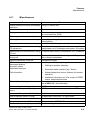
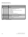
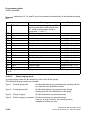
Figures
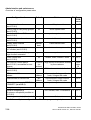
Figures
Figure 2-1
Figure 2-2
Figure 2-3
Figure 2-4
Figure 2-5
Figure 3-1
Figure 3-2
Figure 3-3
Figure 3-4
Figure 3-5
Figure 3-6
Figure 3-7
Figure 3-8
Figure 3-9
Figure 3-10
Figure 3-11
Figure 3-12
Figure 3-13
Figure 3-14
Figure 3-15
Figure 3-16
Figure 3-17
Figure 3-18
Figure 3-19
Figure 3-20
Figure 3-21
Figure 3-22
Figure 3-23
Figure 3-24
Figure 3-25
Figure 5-1
Figure 5-2
Figure 5-3
Figure 5-4
Figure 5-5
Figure 5-6
Figure 5-7
Figure 5-8
Figure 5-9
Figure 5-10
0
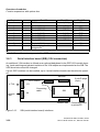
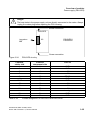
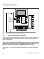
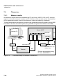
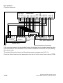
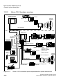
Connection options supported within system environment . . . . . . . . . . . . 2-2
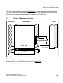
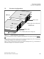
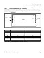
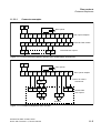
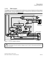
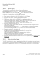
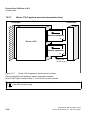
Hicom 108 structural concept . . . . . . . . . . . . . . . . . . . . . . . . . . . . . . . . . . 2-5
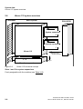
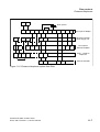
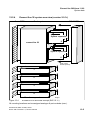
Hicom 112 structural concept . . . . . . . . . . . . . . . . . . . . . . . . . . . . . . . . . . 2-6
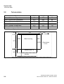
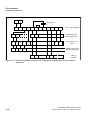
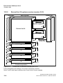
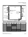
Hicom 118 structural concept . . . . . . . . . . . . . . . . . . . . . . . . . . . . . . . . . . 2-7
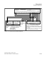
System dimensions and minimum clearances . . . . . . . . . . . . . . . . . . . . . 2-8
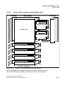
System expansions - slot numbers . . . . . . . . . . . . . . . . . . . . . . . . . . . . . . 3-5
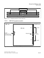
Equipping sequence for extension and trunk modules . . . . . . . . . . . . . . . 3-9
Motherboard interfaces (SW 2.0.1+) . . . . . . . . . . . . . . . . . . . . . . . . . . . . 3-10
Motherboard interfaces (as of SW 2.0.2) . . . . . . . . . . . . . . . . . . . . . . . . 3-11
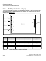
SLAS interfaces. . . . . . . . . . . . . . . . . . . . . . . . . . . . . . . . . . . . . . . . . . . . 3-15
SLAS interfaces. . . . . . . . . . . . . . . . . . . . . . . . . . . . . . . . . . . . . . . . . . . . 3-16
SLU8 interfaces. . . . . . . . . . . . . . . . . . . . . . . . . . . . . . . . . . . . . . . . . . . . 3-17
STLS interfaces. . . . . . . . . . . . . . . . . . . . . . . . . . . . . . . . . . . . . . . . . . . . 3-18
Contact assignment of the S 0 Mini Western socket . . . . . . . . . . . . . . . . 3-18
TLA 4/2 interfaces . . . . . . . . . . . . . . . . . . . . . . . . . . . . . . . . . . . . . . . . . . 3-19
TLA 8 interfaces . . . . . . . . . . . . . . . . . . . . . . . . . . . . . . . . . . . . . . . . . . . 3-20
GEE module, interfaces . . . . . . . . . . . . . . . . . . . . . . . . . . . . . . . . . . . . . 3-21
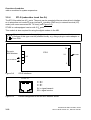
SIB (serial interface board) interfaces . . . . . . . . . . . . . . . . . . . . . . . . . . . 3-22
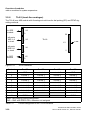
Control relay module – interfaces . . . . . . . . . . . . . . . . . . . . . . . . . . . . . . 3-23
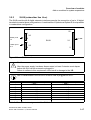
Fax recognition and DDI module - interfaces . . . . . . . . . . . . . . . . . . . . . 3-26
ALUM module interfaces . . . . . . . . . . . . . . . . . . . . . . . . . . . . . . . . . . . . . 3-27
Basic layout of the ALUM module . . . . . . . . . . . . . . . . . . . . . . . . . . . . . . 3-28
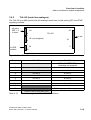
STBG4 module interfaces . . . . . . . . . . . . . . . . . . . . . . . . . . . . . . . . . . . . 3-29
EXM interfaces (2 versions) . . . . . . . . . . . . . . . . . . . . . . . . . . . . . . . . . . 3-30
MPPI interface. . . . . . . . . . . . . . . . . . . . . . . . . . . . . . . . . . . . . . . . . . . . . 3-31
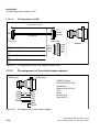
Pin assignment of the V.24 adapter cable. . . . . . . . . . . . . . . . . . . . . . . . 3-32
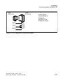
Pin assignment of the modem adapter . . . . . . . . . . . . . . . . . . . . . . . . . . 3-33
Pin assignment of the printer adapter . . . . . . . . . . . . . . . . . . . . . . . . . . . 3-33
PSU/UPS circuitry . . . . . . . . . . . . . . . . . . . . . . . . . . . . . . . . . . . . . . . . . . 3-35
Main distribution frame – screw terminals . . . . . . . . . . . . . . . . . . . . . . . . 3-36
Location, dimensions and minimum clearances . . . . . . . . . . . . . . . . . . . . 5-1
Installing unit . . . . . . . . . . . . . . . . . . . . . . . . . . . . . . . . . . . . . . . . . . . . . . . 5-2
Connecting the UPS battery cable . . . . . . . . . . . . . . . . . . . . . . . . . . . . . . 5-4
Equipping sequence for subscriber and trunk modules . . . . . . . . . . . . . . 5-6
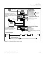
Examples of Mini-Western socket wiring. . . . . . . . . . . . . . . . . . . . . . . . . 5-10
Example of S0 bus socket wiring. . . . . . . . . . . . . . . . . . . . . . . . . . . . . . . 5-11
Pin assignment of the V.24 adapter cable to MB . . . . . . . . . . . . . . . . . . 5-15
Pin assignment of the V.24 adapter cable to SIB . . . . . . . . . . . . . . . . . . 5-16
Pin assignment of the modem adapter . . . . . . . . . . . . . . . . . . . . . . . . . . 5-16
Pin assignment of the printer adapter . . . . . . . . . . . . . . . . . . . . . . . . . . . 5-17
A31003-K16-X001-3-7620, 07/99
Hicom 100 E Version 2.1, Service manual
0-11
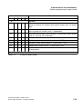
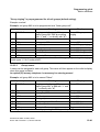
Figures
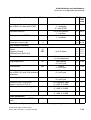
Figure 6-1
Figure 6-2
Figure 6-3
Figure 6-4
Figure 6-5
Figure 6-6
Figure 6-7
Figure 6-8
Figure 7-1
Figure 7-2
Figure 7-3
Figure 7-4
Figure 8-1
Figure 11-1
Figure 11-2
Figure 11-3
Figure 11-4
Figure 11-5
Figure 11-6
Figure 11-7
Figure 11-8
Figure 11-9
Figure 11-10
Figure 11-11
Figure 11-12
Figure 11-13
Figure 11-14
Figure 12-1
Figure 12-2
Figure 12-3
Figure 12-4
Figure 12-5
Figure 12-6
Figure 12-7
Figure 12-8
Figure 12-9
Figure 12-10
Figure 12-11
Figure 12-12
0-12
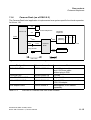
Terminal test. . . . . . . . . . . . . . . . . . . . . . . . . . . . . . . . . . . . . . . . . . . . . . . . 6-4
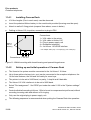
Starting "System administration" . . . . . . . . . . . . . . . . . . . . . . . . . . . . . . . . 6-5
Entering system extension number . . . . . . . . . . . . . . . . . . . . . . . . . . . . . . 6-5
Call Management overview . . . . . . . . . . . . . . . . . . . . . . . . . . . . . . . . . . . . 6-8
Call Management (example) . . . . . . . . . . . . . . . . . . . . . . . . . . . . . . . . . . 6-12
Call Management (example, continued). . . . . . . . . . . . . . . . . . . . . . . . . . 6-13
ISDN intercept day/night. . . . . . . . . . . . . . . . . . . . . . . . . . . . . . . . . . . . . . 6-14
Example of networking . . . . . . . . . . . . . . . . . . . . . . . . . . . . . . . . . . . . . . . 6-18
User data codes . . . . . . . . . . . . . . . . . . . . . . . . . . . . . . . . . . . . . . . . . . . . . 7-1
optiset E memory programming telephone. . . . . . . . . . . . . . . . . . . . . . . . . 7-8
Starting system administration . . . . . . . . . . . . . . . . . . . . . . . . . . . . . . . . . . 7-9
Connection setup via modem for teleservice . . . . . . . . . . . . . . . . . . . . . . 7-44
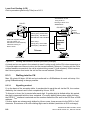
Routing with different network providers (example) . . . . . . . . . . . . . . . . . . 8-6
Entrance telephone, direct door opener connection. . . . . . . . . . . . . . . . . 11-3
Door opener adapter connections . . . . . . . . . . . . . . . . . . . . . . . . . . . . . . 11-4
EGUCOM door opener system from Ackermann (Emmerich) . . . . . . . . . 11-5
Entrance telephone from Grothe . . . . . . . . . . . . . . . . . . . . . . . . . . . . . . . 11-5
Entrance telephone system from Siedle. . . . . . . . . . . . . . . . . . . . . . . . . . 11-6
Entrance telephone system from Ritto . . . . . . . . . . . . . . . . . . . . . . . . . . . 11-7
Entrance telephone system with Telegärtner amplifier and Siedle
entrance telephone. . . . . . . . . . . . . . . . . . . . . . . . . . . . . . . . . . . . . . . . . . 11-8
Doorline M02 entrance telephone . . . . . . . . . . . . . . . . . . . . . . . . . . . . . . 11-9
Doorline M02 entrance telephone (four receiving extensions for
doorbell). . . . . . . . . . . . . . . . . . . . . . . . . . . . . . . . . . . . . . . . . . . . . . . . . 11-10
TFE/V adapter interfaces . . . . . . . . . . . . . . . . . . . . . . . . . . . . . . . . . . . . 11-11
Contact assignment for possible voice modules . . . . . . . . . . . . . . . . . . 11-12
Connection to Siedle TLM 511-01, Ritto 5760 or Grothe TS 6216
entrance telephone. . . . . . . . . . . . . . . . . . . . . . . . . . . . . . . . . . . . . . . . . 11-13
Overview of Caracas Desk configuration . . . . . . . . . . . . . . . . . . . . . . . . 11-15
Wall mounting with closed housing and opened hinged cover . . . . . . . . 11-16
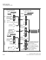
Euroset line 36 connection options supported within system
environment . . . . . . . . . . . . . . . . . . . . . . . . . . . . . . . . . . . . . . . . . . . . . . . 12-1
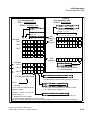
Hicom 118-2 connection options supported within system environment . 12-2
Two-box system assembly (minimum/maximum clearances) . . . . . . . . . 12-3
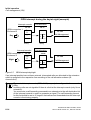
Euroset line 36 structural concept (SW 2.0.1+) . . . . . . . . . . . . . . . . . . . . 12-5
Euroset line 36 structural concept (SW 2.0.2) . . . . . . . . . . . . . . . . . . . . . 12-6
Hicom 118-2 basic system structural concept . . . . . . . . . . . . . . . . . . . . . 12-7
Hicom 118-2 expansion box structural concept . . . . . . . . . . . . . . . . . . . . 12-8
Motherboard interfaces – Euroset line 36. . . . . . . . . . . . . . . . . . . . . . . . 12-13
MB interfaces, Hicom 118-2 basic box . . . . . . . . . . . . . . . . . . . . . . . . . . 12-15
Equipping sequence for the basic box . . . . . . . . . . . . . . . . . . . . . . . . . . 12-17
EB interfaces, Hicom 118-2 expansion box . . . . . . . . . . . . . . . . . . . . . . 12-17
Equipping sequence for the expansion box . . . . . . . . . . . . . . . . . . . . . . 12-18
A31003-K16-X001-3-7620, 07/99
Hicom 100 E Version 2.1, Service manual
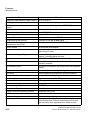
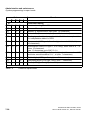
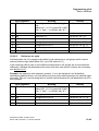
Tables
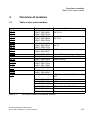
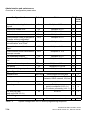
Tables
0
Table 2-1
Table 2-2
Table 2-3
Table 2-4
Table 2-5
Table 3-1
Table 3-2
Table 3-3
Table 3-4
Table 3-5
Table 3-6
Table 3-7
Table 3-8
Table 3-9
Table 3-10
Table 3-11
Table 3-12
Table 3-13
Table 3-14
Table 3-15
Table 3-16
Table 3-17
Table 3-18
Table 3-19
Table 3-20
Table 3-21
Table 3-22
Table 3-23
Table 3-24
Table 3-25
Table 3-26
Table 3-27
Table 3-28
Table 5-1
Table 5-2
Table 5-3
Table 6-1
Table 6-2
Table 7-1
Table 7-2
Documentation . . . . . . . . . . . . . . . . . . . . . . . . . . . . . . . . . . . . . . . . . . . . . 2-3
System dimensions in mm . . . . . . . . . . . . . . . . . . . . . . . . . . . . . . . . . . . . 2-8
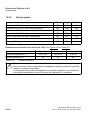
Ranges (with J-Y(ST) 2x2x0.6) for terminal interfaces . . . . . . . . . . . . . . . 2-9
Climatic conditions . . . . . . . . . . . . . . . . . . . . . . . . . . . . . . . . . . . . . . . . . . 2-9
Basic configuration and system expansions . . . . . . . . . . . . . . . . . . . . . . 2-10
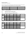
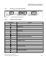
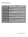
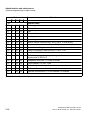
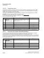
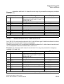
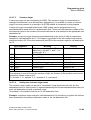
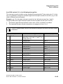
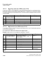
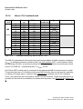
Item code numbers with national versions . . . . . . . . . . . . . . . . . . . . . . . . 3-1
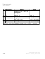
Country codes . . . . . . . . . . . . . . . . . . . . . . . . . . . . . . . . . . . . . . . . . . . . . . 3-3
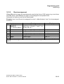
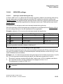
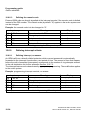
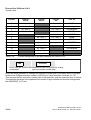
Possible expansions . . . . . . . . . . . . . . . . . . . . . . . . . . . . . . . . . . . . . . . . . 3-6
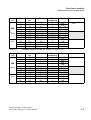
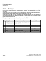
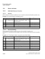
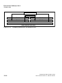
Standard numbering, MB 2/4 Hicom 108 (SW 2.0.1) . . . . . . . . . . . . . . . . 3-6
Standard numbering, MB 2/4 Hicom 108 (as of SW 2.0.1+) . . . . . . . . . . . 3-6
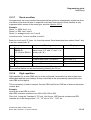
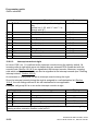
Standard numbering, MB 4/4 Hicom 112 (SW 2.0.1) . . . . . . . . . . . . . . . . 3-7
Standard numbering, MB 4/4 Hicom 112 (as of SW 2.0.1+) . . . . . . . . . . . 3-7
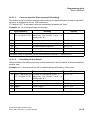
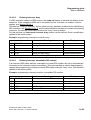
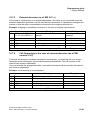
Standard numbering, MB 6/4 Hicom 118 (as of SW 2.0.1+) . . . . . . . . . . . 3-8
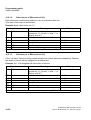
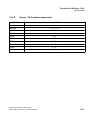
Contact assignment of the MB interfaces 2/4 Hicom 108 . . . . . . . . . . . . 3-12
Contact assignment of the MB interfaces 4/4 Hicom 112 . . . . . . . . . . . . 3-12
Contact assignment of the MB interfaces 6/4 Hicom 118 . . . . . . . . . . . . 3-12
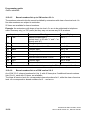
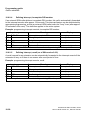
Add-on modules for system expansions . . . . . . . . . . . . . . . . . . . . . . . . . 3-13
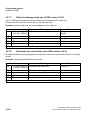
Contact assignment of the SLAS interfaces . . . . . . . . . . . . . . . . . . . . . . 3-15
Contact assignment of the SLAS interfaces . . . . . . . . . . . . . . . . . . . . . . 3-16
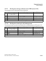
Contact assignment of the SLU interfaces . . . . . . . . . . . . . . . . . . . . . . . 3-17
Contact assignment of the TLA 4/2 interfaces . . . . . . . . . . . . . . . . . . . . 3-19
Contact assignment of the TLA 8 interfaces . . . . . . . . . . . . . . . . . . . . . . 3-20
GEE module, national versions . . . . . . . . . . . . . . . . . . . . . . . . . . . . . . . . 3-21
Contact assignment of the GEE module . . . . . . . . . . . . . . . . . . . . . . . . . 3-22
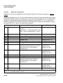
Load capacity of control relay outputs. . . . . . . . . . . . . . . . . . . . . . . . . . . 3-23
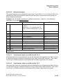
Contact assignment of STRB module . . . . . . . . . . . . . . . . . . . . . . . . . . . 3-24
Contact assignment of the fax recognition and DDI module . . . . . . . . . . 3-26
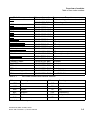
Contact assignment of the ALUM module. . . . . . . . . . . . . . . . . . . . . . . . 3-28
Contact assignment of the STBG module . . . . . . . . . . . . . . . . . . . . . . . . 3-29
Contact assignment of the EXM/MPPI modules . . . . . . . . . . . . . . . . . . . 3-30
Power supply (PSU/UPS) – derived voltages . . . . . . . . . . . . . . . . . . . . . 3-34
Bridging times for different battery capacities . . . . . . . . . . . . . . . . . . . . . 3-34
Contact assignment of PSU/UPS1 and PSU/UPS2 . . . . . . . . . . . . . . . . 3-35
Power split PSU1/UPS1 for Hicom 108/112 . . . . . . . . . . . . . . . . . . . . . . . 5-3
Power split PSU2/UPS2 for Hicom 118. . . . . . . . . . . . . . . . . . . . . . . . . . . 5-3
MSN - default numbering . . . . . . . . . . . . . . . . . . . . . . . . . . . . . . . . . . . . . 5-9
National codes. . . . . . . . . . . . . . . . . . . . . . . . . . . . . . . . . . . . . . . . . . . . . . 6-2
Error messages for network settings. . . . . . . . . . . . . . . . . . . . . . . . . . . . 6-16
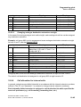
Codes/extension numbers without S key and * or # . . . . . . . . . . . . . . . . . 7-2
Codes for accessing services . . . . . . . . . . . . . . . . . . . . . . . . . . . . . . . . . . 7-3
A31003-K16-X001-3-7620, 07/99
Hicom 100 E Version 2.1, Service manual
0-13
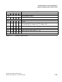
Tables
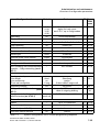
Table 7-3
Table 7-4
Table 7-5
Table 7-6
Table 7-7
Table 8-1
Table 8-2
Table 8-3
Table 8-4
Table 8-5
Table 8-6
Table 8-7
Table 11-1
Table 11-2
Table 12-1
Table 12-5
Table 12-7
0-14
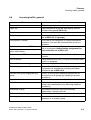
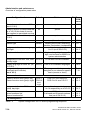
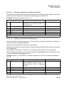
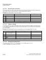
Code groups for expert mode. . . . . . . . . . . . . . . . . . . . . . . . . . . . . . . . . . . 7-9
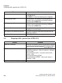
Codes for expert mode . . . . . . . . . . . . . . . . . . . . . . . . . . . . . . . . . . . . . . . 7-10
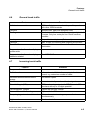
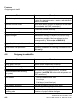
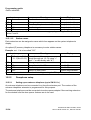
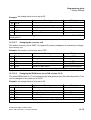
System configuration via PC and/or programming telephone . . . . . . . . . 7-31
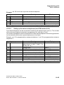
Classes of service up to SW 2.0.1+ . . . . . . . . . . . . . . . . . . . . . . . . . . . . . 7-48
Classes of service as of SW 2.0.2 . . . . . . . . . . . . . . . . . . . . . . . . . . . . . . 7-48
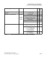
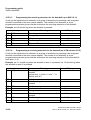
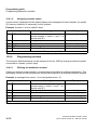
Exception table . . . . . . . . . . . . . . . . . . . . . . . . . . . . . . . . . . . . . . . . . . . . . . 8-1
Routing table . . . . . . . . . . . . . . . . . . . . . . . . . . . . . . . . . . . . . . . . . . . . . . . 8-2
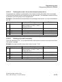
Configuration example for single-stage LCR . . . . . . . . . . . . . . . . . . . . . . . 8-3
Configuration example for two-stage LCR . . . . . . . . . . . . . . . . . . . . . . . . . 8-4
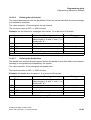
Configuration example for DICS. . . . . . . . . . . . . . . . . . . . . . . . . . . . . . . . . 8-8
Exception table for DICS . . . . . . . . . . . . . . . . . . . . . . . . . . . . . . . . . . . . . . 8-8
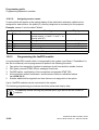
Configuration example for conversion table . . . . . . . . . . . . . . . . . . . . . . . . 8-9
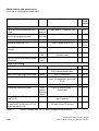
TFE/V contact assignment . . . . . . . . . . . . . . . . . . . . . . . . . . . . . . . . . . . 11-12
Overview of Caracas Desk item code numbers . . . . . . . . . . . . . . . . . . . 11-15
Add-on modules for Hicom 118-2 system expansions . . . . . . . . . . . . . . . 12-9
Overview of item code numbers . . . . . . . . . . . . . . . . . . . . . . . . . . . . . . . 12-12
Contact assignment of the MB interfaces - Euroset line 36 . . . . . . . . . . 12-13
A31003-K16-X001-3-7620, 07/99
Hicom 100 E Version 2.1, Service manual
Important Information
Safety information
1
Important Information
1.1
Safety information
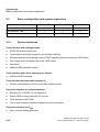
The following information is aimed at service personnel and authorized specialists. Only these
persons are permitted to work on the installation.
Read through all information on the equipment carefully, and follow all safety information. Also
obtain information concerning the emergency numbers.
Always contact your manager before starting any work where the necessary safety does not
appear to be present (e.g. hazards due to gas explosion or humidity).
Safety symbols
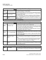
Potential sources of danger in this description are identified by means of the following symbols:
!
Danger
This symbol calls attention to a situation that could cause serious
injury or death to a person.
!
Warning
This symbol calls attention to a situation that could cause serious
injury to a person.
!
Caution
This symbol calls attention to a situation that could damage or
destroy hardware or software.
This symbol identifies useful informations.
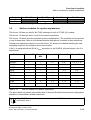
Further symbols for defining the source of danger in greater detail1:
Electricity
Weight
Heat
Fire
Chemicals
ESD*
Laser
* Electrostatic discharge
1. These symbols are not usually used in the manual. They’re an explanation of the symbols that can be depicted on the systems.
A31003-K16-X001-3-7620, 07/99
Hicom 100 E Version 2.1, Service manual
1-1
Important Information
Safety information
1.1.1
Safety information: Danger
●
Do not open the power supply. The device may only repaired by authorized personnel.
Opening the device and tampering with it can endanger your life.
●
Before applying power to the system or connecting extensions, ensure that the system is
correctly carthed.
Never operate the equipment with protective earthing conductor disconnected!
●
Voltages above 30 V AC (alternating current) or 60 V DC (direct current) are dangerous.
●
If the power cable appears to be damaged, replace it immediately.
●
Immediately replace any damaged safety equipment (covers, labels and protective cables).
●
If the maintenance work requires the power supply of the system to be shut down:
–
Use the shut-off switch to disconnect the system from the power supply circuit, and secure the shut-off device mechanically so that it cannot be used by other persons.
–
Affix the information "DO NOT OPERATE" to the disconnect device.
A disconnect device can be a shut-off switch (main switch) or protective switch (fuse/
automatic cut out).
–
Before starting any work on the installation, establish the location of the disconnect device.
●
If you are performing work on circuits with hazardous voltages, always work together with
a partner who is familiar with the location of the switch for the power supply.
●
Always ensure adequate insulation when touching powered circuits.
●
Ensure that the installation is not powered by an additional power supply, or that it is protected via an additional fuse or an additional main switch.
●
Before starting any work, check whether the corresponding circuits are still on power. Never take it for granted that all circuits have reliably been disconnected from the power supply
when a fuse or a main switch has been switched off.
●
During a thunderstorm, you should not connect or remove telephone lines and PCB
boards.
●
Expect to encounter leakage current from the telecommunication network.
●
Ensure that, whenever work is carried out on an open installation, the installation is never
left unsupervised.
1-2
A31003-K16-X001-3-7620, 07/99
Hicom 100 E Version 2.1, Service manual
Important Information
Safety information
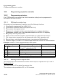
1.1.2
Safety information: Warning
●
There is the risk of an explosion if the Nickel Cadmium Batteryis not replaced correctly. The
lithium battery must be replaced only by the same or equivalent types recommended by
the manufacturer.
●
Be aware of additional dangers with low voltages and large cross-sections. Cables with a
large cross-section generally have lower voltages, although the current strengths are higher. This results in particular risks, e.g. in the event of short circuits.
●
When working on the installations, never wear loose clothing and always tie back long hair.
●
Never wear jewellery, metal watch straps or for instance metal fittings and rivets on items
of clothing. There is a risk of injury and short circuit.
●
The surface of a mirror is conductive! Never touch powered circuits with a mirror; you might
injure yourself and/or at least cause short-circuit damage.
●
Always wear the necessary eye protection whenever appropriate.
●
Always wear a protective helmet where falling objects might injure you.
●
Always disconnect the power supply when you are working directly next to a power supply
unit or direct current converter, unless the work instructions expressly permit you to work
without having to shut off the power.
●
Never try to lift heavy objects without assistance.
●
In case of laser radiation: do not stare into the beam.
A31003-K16-X001-3-7620, 07/99
Hicom 100 E Version 2.1, Service manual
1-3
Important Information
Safety information
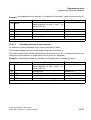
1.1.3
Safety information: Caution
●
Check the set nominal voltage of the installation (operating instructions and type plate).
●
As long as the power supply is switched on, always observe the greatest caution when performing measurements on powered components and maintenance work on plug-in cards,
PC boards and covers.
●
To protect against the electrostatic discharge (ESD):
–
Always wear the wristband before performing any work on PCB boards and modules.
–
Only transport PC boards in suitable protective packaging.
–
Always place PC boards on a grounded conducting base, and do not process the PC
boards anywhere else.
–
Only use grounded soldering irons.
●
Only use tools and testers suitable for the job. Do not use broken tools and testers, inspect
them regularly.
●
Find out the location of the main switch for the power supply of the system. Follow the
appropriate instructions.
●
Install cables in such a way that they do not pose an accident risk (i.e. so that they do not
trip anybody up) and also so that they are not damaged.
1-4
A31003-K16-X001-3-7620, 07/99
Hicom 100 E Version 2.1, Service manual
Important Information
Safety information
1.1.4
General information
●
If the installation is brought into the operating premises from a cold environment,
condensation may occur. Wait until the temperature of the installation has adjusted to the
ambient temperature and until the installation is absolutely dry before you start it up.
●
Before starting wall assembly, check whether the load-bearing capacity of the wall is
adequate, e.g. in the event of plasterboard walls.
●
When maintenance work has been completed, always re-install all safety equipment in the
right place.
●
Check your tools regularly. Only use intact tools.
●
Close the doors after test and maintenance work has been completed.
●
All cables and lines which leave a system cabinet must be screened at least between the
connection point in the cabinet and the point at which the cable leaves the cabinet. Use a
clip and pressure screw to contact all screen fabric to the cabinet outlet. This is also
applicable for permanently connected service equipment.
●
Connect all cables only to the specified connection points.
●
Do not install any external modems in the installation cabinets.
●
Do not allow readily flammable materials to be stored near the installation or in the
installation room.
●
Ensure good lighting at the workplace.
●
Untidiness at the workplace involves the risk of injuries.
A31003-K16-X001-3-7620, 07/99
Hicom 100 E Version 2.1, Service manual
1-5
Important Information
Safety information
1.1.5
Behaviour in emergencies
●
In the event of accidents, remain calm and considered.
●
Always switch off the power supply before you touch an accident victim.
●
If you are not able to immediately switch off the power supply, only touch the victim with
non-conducting materials (e.g. a broom handle made of wood), and first of all try to isolate
the victim from the power supply.
●
You must be familiar with first-aid principles in the event of electricity injuries. An urgent
need in such emergencies is fundamental knowledge of the various methods of
resuscitation if the victim has stopped breathing or if the victim’s heart is no longer beating,
as well as first aid for treating burns.
●
If the victim is not breathing, immediately perform mouth-to-mouth or mouth-to-nose
resuscitation.
●
If you have appropriate training, immediately perform heart massage if the victim’s heart is
not beating.
●
Immediately call an ambulance or the emergency doctor. Provide the following information
in the following sequence:
–
Where did the accident take place?
–
What has happened?
–
How many injured?
–
What type of injuries?
–
Wait for queries.
1.1.6
Accident reporting
●
Immediately report all accidents, "near accidents" and potential sources of danger to your
manager.
●
Report all electrical shocks, no matter how small.
1-6
A31003-K16-X001-3-7620, 07/99
Hicom 100 E Version 2.1, Service manual
Important Information
Data protection and data security
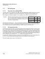
1.2
Data protection and data security
This system also processes and uses personal data, e.g. for call charge metering purposes,
the displays and for recording user data.
In Germany, the processing and use of such personal data are subject to various regulations,
including the regulations of the Federal Data Protection Law (Bundesdatenschutzgesetz =
BDSG). For other countries, please follow the appropriate national laws.
The aim of data protection is to protect the rights of individuals being affected by use of his personal data.
In addition, the aim of data protection is to ensure that data are not corrupted when processed
and that one’s own interests and the interests of other parties which need to be protected are
not affected.
Members of Siemens and Siemens Rolm staff are required to observe business and data secrecy as a result of the company’s work rules.
In order to ensure that the statutory requirements during service - whether during "on-site service" or during "tele service" - are consistently met, you should always observe the following
rules. You will not only maintain the interests of your/our customers, you will also avoid personal
consequences.
Contribute to maintain data protection and data security with your conscious action:
●
Ensure that only appropriately authorized persons have access to customer data.
●
Take full advantage of all options of allocating passwords; do not inform unauthorized
persons of passwords, e.g. by means of a written note.
●
Ensure that no unauthorized person is able to process (store, modify, transmit, disable,
delete) or use customer data in any way.
●
Prevent unauthorized persons from gaining access to data media, e.g. on backup disks or
protocol printouts. This is applicable for service calls as well as for storage and transport.
●
Ensure that data media which are no longer required are completely destroyed. Ensure
that no papers remain generally available.
Work together with your contacts of the customer: This creates mutual confidence and reduces
your own workload.
A31003-K16-X001-3-7620, 07/99
Hicom 100 E Version 2.1, Service manual
1-7
Important Information
Data protection and data security
1-8
A31003-K16-X001-3-7620, 07/99
Hicom 100 E Version 2.1, Service manual
System data
General system description
2
System data
2.1
General system description
The Hicom 108/112/118 systems belonging to the Hicom 100 E product family are compact,
digital, Euro-ISDN-compatible telephone systems suitable for analogue and digital network access and for analogue and digital terminals. The basic configuration of each system can be expanded and supplemented in different ways. See Figure 2-2 (Hicom 108), Figure 2-3 (Hicom
112), Figure 2-4 (Hicom 118).
The Hicom 108/112/118 systems are of flatpack design, i.e. without a backplane. All basic functions are incorporated on the motherboard (see Figure 3-4). The systems have plastic housings
consisting of base, intermediate section, and cover. The Hicom 118 has an additional intermediate frame to accommodate system expansions. The housing sections are held together by
easily released latches.
The system expansions are of the plug-in type. The Hicom 108 has 1 slot (for analogue trunk
or S0 line modules), the Hicom 112 has 2 slots (for analogue trunk and S0 line modules), and
the Hicom 118 has 4 slots for further system expansions with line and subscriber modules.
The function expansions (optional) are attached with their own housings to the basic housing.
The power supply (PSU/UPS) is also attached mechanically and electrically to the basic housing and is additionally secured by screws.
The integral main distribution frame is part of the basic housing. Plug-in connectors (terminal
blocks) render the line network easily separable from the system cards.
A31003-K16-X001-3-7620, 07/99
Hicom 100 E Version 2.1, Service manual
2-1
System data
Hardware overview
2.2
Hardware overview
Hicom 100 E
Analogue
tnk.
S0 tnk./
extensions
N
N
N
123
456
789
00
108
112
118
ABC
DEF
ABC
DEF
GHI
JKL
MNO
GHI
MNO
PQRS
TUV
WXYZ
PQRS
TUV
N
N
0
optiset E memory with
optiset expansion
Hicom 300
optiset E advance plus
with optiset expansion
UP0/E interface
123
456
789
00
ABC
DEF
ABC
DEF
GHI
MNO
JKL
GHI
MNO
PQRS
TUV
W
XYZ
PQRS
TUV
0
Voice
terminal
Group 3 fax
optiset E advance plus
optiset E memory
- optiset E entry
- optiset E advance
- optiset standard
profiset
- optiset memory
gigaset
megaset
Entrance telephone
a/b interface
gigaset i
Personal computer
V.24 interface
Call charge computer/PC
or printer
Group 4 fax
Figure 2-1
2-2
Connection options supported within system environment
A31003-K16-X001-3-7620, 07/99
Hicom 100 E Version 2.1, Service manual
System data
Documentation
2.3
Documentation
Designation
Item code number
Hicom 100 E Service Manual (German)
Hicom 100 E Service Manual (Dutch)
Hicom 100 E Service Manual (Italian)
Hicom 100 E Service Manual (Finnish)
Hicom 100 E Service Manual (English)
Hicom 100 E Service Manual (French)
Hicom 100 E Service Manual (Spanish)
Hicom 100 E Service Manual (Portuguese)
A31003-K16-X-*-20 (up to SW 2.0.1+)
A31003-K16-X-*-5420
A31003-K16-X-*-7220
A31003-K16-X-*-7320
A31003-K16-X-*-7620
A31003-K16-X-*-7720
A31003-K16-X-*-7820
A31003-K16-X-*-7920
Hicom 100 E Electronic Service Manual
P31003-K16-X001-*-20
(up to SW 2.1)
German and other languages
Hicom 100 E Customer Datasheets
A31003-K16-X-*-K6
German and other languages
Service Instructions for
telephones, adapters, add-on units:
optiset E entry
optiset E basic
optiset E standard
optiset E advance
optiset E advance plus
optiset E memory
optiset E key module (add-on units)
optiset E analogue adapter
optiset E data adapter
optiset E ISDN adapter
optiset E phone adapter
optiset E acoustic adapter
optiset E distance adapter S
optiset E distance adapter M
A31003-E8000-A100-*-20
German and other languages
(see above)
User Manual (SW 2.0.1+):
System Support/Administration
A31003-K3000-B341-*-19
German and other languages
(see above)
User Manual (SW 2.0.2):
System Support/Administration
A31003-K16-B455-*-19
German and other languages
(see above)
Table 2-1
Documentation
A31003-K16-X001-3-7620, 07/99
Hicom 100 E Version 2.1, Service manual
2-3
System data
System types
Designation
User Manual (SW 2.1)
System Support/Administration
Table 2-1
Item code number
A31003-K16-B546-*-19
German and other languages
(see above)
Documentation
Documentation is available from your Dealer.
2.4
System types
The systems are available in the following configurations:
Hicom 108 with one slot, 2 U P0/E and 4 a/b extension interfaces (see Figure 2-2)
Hicom 112 with two slots, 4 UP0/E and 4 a/b extension interfaces (see Figure 2-3)
Hicom 118 with four slots, 6 UP0/E and 4 a/b extension interfaces (see Figure 2-4)
Nameplate on the housing base near the main distribution frame
A distinction is made between the following components:
●
Basic system, motherboard with V.24 interface via mini-DIN connector and optional EXM/
MPPI (external music on hold)
●
PSU1 power supply unit for Hicom 108 and 112 (see Section 3.8)
UPS1 uninterruptible power supply for Hicom 112 (see Section 3.8)
PSU2 power supply unit for Hicom 118 (see Section 3.8)
UPS2 uninterruptible power supply for Hicom 118 (see Section 3.8)
●
System expansions
The modular design permits almost any slot assignments (see Table 3-12).
SLAS subscriber line analogue with 4, 8 or 16 a/b interfaces
SLU 8 subscriber line UP0/E with 8 UP0/E interfaces
STLS subscriber/trunk line S0 with 4 S0 interfaces or 2 S0 interfaces
TLA trunk line analogue with 2, 4 or 8 analogue trunk interfaces
●
Function expansions (see Section 3.6)
ALUM power failure transfer with 4 transfer options for analogue lines
Fax/DDI with announcement (DTMF)
GEE call-charge pulse recognition for 4 analogue trunk interfaces
SIB serial interface board (optional V.24 interface)
STRB control relay module with 4 control inputs and 4 control outputs
STBG4 current limiting module for France
WS48/ÜFS analogue DDI trunk for Austria
EXM/MPPI - module for MOH
2-4
A31003-K16-X001-3-7620, 07/99
Hicom 100 E Version 2.1, Service manual
System data
Hicom 108 system overview
The MDF (main distribution frame) (see Section 3.9) expands automatically with the system,
since each expansion provides the necessary interfaces. Any space that may be required for
future function expansions must be taken into account in the initial plans.
2.5
Hicom 108 system overview
Cover/MDF
Basic system
PSU1
System expansion
1
Hicom 108
Plug in and
secure (screw)
1 ... 4
Plug in
Function expansions
Figure 2-2
Hicom 108 structural concept
Slot 1 for system expansions:
Analogue (TLA2) or S0 (STLS2) trunk module (see Table 3-12)
A31003-K16-X001-3-7620, 07/99
Hicom 100 E Version 2.1, Service manual
2-5
System data
Hicom 112 system overview
2.6
Hicom 112 system overview
Basic system
Cover/MDF
PSU1/UPS1
System expansion
3
System expansion
1
Hicom 112
Plug in and
secure (screw)
1... 4
Plug in
Function expansions
Figure 2-3
Hicom 112 structural concept
Slots 1 and 3 for system expansions:
Freely assignable with line modules (see Table 3-12)
2-6
A31003-K16-X001-3-7620, 07/99
Hicom 100 E Version 2.1, Service manual
System data
Hicom 118 system overview
2.7
Hicom 118 system overview
Cover/MDF
Basic system
PSU2/UPS2
System expansion
4
3
System expansion
2
1
Hicom 118
Plug in and
secure (screw)
1
2
3
4
Plug in
Function expansions
Figure 2-4
Hicom 118 structural concept
Slots 1 to 4 for system extensions:
Freely assignable with line and/or subscriber modules (see Table 3-12)
A31003-K16-X001-3-7620, 07/99
Hicom 100 E Version 2.1, Service manual
2-7
System data
Technical data
2.8
Technical data
System
Width
Height
Depth
Hicom 108 basic configuration
470
370
80
Hicom 108 with max. expansions
470
630
80
Hicom 112 basic configuration
470
370
80
Hicom 112 with max. expansions
470
630
80
Hicom 118 basic configuration
470
370
110
Hicom 118 with max. expansions
470
630
110
Table 2-2
System dimensions in mm
470
200
MDF
Basic housing
300
PSU
370
(UPS)
Dimensions
in mm
Module (max. 4)
300
Module
Figure 2-5
2-8
System dimensions and minimum clearances
A31003-K16-X001-3-7620, 07/99
Hicom 100 E Version 2.1, Service manual
System data
Technical data
Terminal interfaces
Range in m
ISDN S0 point-to-point connection
< 600
ISDN S0 point-to-multipoint connection
< 150
ISDN S0 terminal box to terminal
< 10
a/b extensions
< 2000
UP0/E console to master
< 1000
UP0/E master to slave
< 100
Table 2-3
Ranges (with J-Y(ST) 2x2x0.6) for terminal interfaces
Ambient temperature in °C
Relative humidity in %
Table 2-4
Operation
Transport
Storage
+5 to +40
-40 to +70
-5 to +45
85
95
95
Climatic conditions
Caution
!
Do not expose to direct sunlight and keep appliance away from heaters to avoid of
the danger of localised overheating.
If condensation forms, allow the appliance to dry before operation.
It is essential to ensure that condensation cannot form while the appliance is in operation.
A31003-K16-X001-3-7620, 07/99
Hicom 100 E Version 2.1, Service manual
2-9
System data
Basic configuration and system expansions
2.9
Basic configuration and system expansions
Hicom 108
Hicom 112
Hicom 118
UP0/E interfaces - MB
2
4
6
a/b interfaces - MB
4
4
4
Slots for expansions
1
2
4
Table 2-5
2.10
Basic configuration and system expansions
System interfaces
Trunk interface with analogue trunk
●
DTMF, DP without earth recall
●
Tone detector (dial-tone interpreter) for automatic dialling
●
Analogue pseudo direct dialling in using DTMF signalling with announcement (DDI option)
●
Call-charge pulse recognition per trunk (GEE option)
●
Fax option
●
Mixed fax/DDI operation (option)
Trunk interface with direct dialling in for Austria
●
WS48 and ÜFS methods
Trunk interface and extension interface S0
●
System synchronisation to trunk clock with selection circuit
Extension interface for normal telephone
●
Bilingual: DP or DTMF (12-key keyboard)
●
Range 2000 m using cable with 0.6 mm dia
●
Flash detection with DTMF
●
One or more entrance telephone adaptors can be connected
Extension interface for UP0/E
●
Only in-house cabling permitted
2-10
A31003-K16-X001-3-7620, 07/99
Hicom 100 E Version 2.1, Service manual
Overview of modules
Table of item code numbers
3
Overview of modules
3.1
Table of item code numbers
Module/component
MB 6/4
MB 4/4
MB 2/4
MB 6/4
MB 4/4
MB 2/4
MB 6/4
MB 4/4
MB 2/4
MB 6/4
MB 4/4
MB 6/4
EB118-2
MB 2/4
SLAS16
SLAS8
SLAS4
SLU8
STLS4
STLS2
TLA8
Item code number
S30817-Q920-A501
S30817-Q920-B501
S30817-Q920-C501
S30817-Q920-A601
S30817-Q920-B601
S30817-Q920-C601
S30817-Q920-A701
S30817-Q920-B701
S30817-Q920-C701
S30817-Q920-A711
S30817-Q920-B711
S30817-Q920-K701
S30817-Q952-A601
S30817-Q920-H601
S30817-Q925-A301
S30817-Q921-C301
S30817-Q921-D301
S30817-Q922-A301
S30817-Q924-A313
S30817-Q924-B313
S30817-Q926-A301
S30817-Q926-A308
S30817-Q926-A311
S30817-Q926-A312
S30817-Q926-A314
S30817-Q926-A315
S30817-Q926-A316
Table 3-1
Remarks
SW 2.0.1+
SW 2.0.2
SW 2.1
POR
Hicom 118-2 (two-box system)
Expansion module for Hicom 118-2
Hicom 108 NDL
GER, CHN, AUS, CIS, CRE, LUX, FIN,
AST
GBR,IND
POR
SPA
BEL,IM, IRL, ITL, POL, TRK
NDL
FRA
Item code numbers with national versions
A31003-K16-X001-3-7620, 07/99
Hicom 100 E Version 2.1, Service manual
3-1
Overview of modules
Table of item code numbers
Module/component
TLA4
TLA2
Item code number
S30817-Q923-A308
S30817-Q923-A311
S30817-Q923-A312
S30817-Q923-A313
S30817-Q923-A314
S30817-Q923-A315
S30817-Q923-A316
S30817-Q923-B308
S30817-Q923-B311
S30817-Q923-B312
S30817-Q923-B313
S30817-Q923-B314
GEE12
S30817-Q923-B315
S30817-Q923-B316
S30817-Q951-A313
S30817-Q951-A317
S30817-Q931-A301
GEE50
SIB
STRB
Fax/DDI
STBG4
ALUM4
Door opener
TFE/V
S30817-Q931-A302
S30817-Q931-A311
S30817-Q931-A312
S30817-Q931-A314
S30817-Q931-B315
S30122-K5685-X
S30817-Q932-A
S30817-Q933-A301
S30817-Q934-A
S30817-Q935-A
S30817-Q930-A100
S30817-Q936-A313
GEE16
Table 3-1
3-2
Remarks
GBR,IND, RSA
POR
SPA
GER, CHN, FIN, AUS
ARG, BEL, DEN, GRE, IDS, IM, ITL,
MAL, PHI, POL, CIS, SIN, SWZ, THA,
HNG
BRA, NDL
FRA
GBR, IND, RSA
POR
SPA
GER, CHN, FIN, AUS
ARG, BEL, DEN, GRE, IDS, IM, ITL,
MAL, PHI, POL, POR, CIS, SIN, SWZ,
THA, HNG
BRA, NDL
FRA
BEL, GER, IM, LUX, CIS, HNG
FIN, RSA
FRA, IDS, IM, IRL, MAL, PHI, CIS, SIN,
SWZ, THA, HNG
AUS
POR
SPA
ITL
FRA, GBR, NDL
FRA
As of 04/96: S30817-Q930-A200
Item code numbers with national versions
A31003-K16-X001-3-7620, 07/99
Hicom 100 E Version 2.1, Service manual
Overview of modules
Table of item code numbers
Module/component
EXM
MPPI
OPA (options adapter)
PSU1
PSU2
UPS1
UPS2
Battery box
V.24 adapter cable
V.24 adapter cable
V.24 printer adapter
V.24 adapter modem
108/112 ribbon cable
118 ribbon cable
Plug connector
Plug connector
EXM/MPPI cable
EXM/MPPI cable
GEE cable
GEE cable
PSU connecting cable
PSU connecting cable
Table 3-1
Item code number
S30817-H902-A401
S30817-H902-B401
S30122-H5380-X
S30122-K5525-X
S30122-K5448-X312
S30122-K5449-X312
S30122-K5450-X312
S30122-K5451-X312
S30122-K5403-X
S30122-X5468-X
C39195-Z7267-C5
S30122-K5597-X
S30122-K5597-X100
C39195-A7001-B83
C39195-A7018-B82
C39334-Z7089-C14
C39334-Z7089-C13
C39195-A7001-B88
C39195-A7001-B111
C39165-A7001-B87
C39165-A7001-B110
C39195-A7001-B85
C39195-A7001-B112
Remarks
Without coding, with screw terminals
With coding, without screw terminals
MB only
SIB only
MB <-> system expansions
MB <-> system expansions
4-pin
8-pin
Uncoded
Coded
Uncoded
Coded
Up to SW 2.0.1+
As of SW 2.0.2
Item code numbers with national versions
Abbrev.
Country
Abbrev.
ARG
Argentina
IND
India
AST
Australia
IRL
Ireland
AUS
Austria
ITL
Italy
BEL
Belgium
LUX
Luxembourg
BRA
Brazil
MAL
Malaysia
CHN
China
NDL
Netherlands
Table 3-2
Country
Country codes
A31003-K16-X001-3-7620, 07/99
Hicom 100 E Version 2.1, Service manual
3-3
Overview of modules
Table of item code numbers
Abbrev.
Abbrev.
Country
CIS
Commonwealth of Independent
States
NOR
Norway
CRE
Czech Republic
PHI
Philippines
DEN
Denmark
POL
Poland
FIN
Finland
POR
Portugal
FRA
France
RSA
Republic of South Africa
GBR
Great Britain
SIN
Singapore
GER
Germany
SPA
Spain
GRE
Greece
SWD
Sweden
HNG
Hungary
SWZ
Switzerland
IDS
Indonesia
THA
Thailand
IM
International Markets
TRK
Turkey
Table 3-2
3-4
Country
Country codes
A31003-K16-X001-3-7620, 07/99
Hicom 100 E Version 2.1, Service manual
Overview of modules
Overview of configurations
3.2
Overview of configurations
MDF side
Slot 4
Slot 3
Ribbon cable
MB
Ribbon cable colour coding (red)
PSU/UPS side
Slot 2
Slot 1
Ribbon cable
Ribbon cable colour coding (red)
Max. 4 function expansions
Figure 3-1
System expansions - slot numbers
The overview shows the variety of possible combinations for the systems (see also Section
3.5).
Hicom 108 has one slot that is used only for line modules (analogue trunk or So). A combination
of ISDN and analogue trunk connections is not possible.
Hicom 112 has two slots that are used for line modules (analogue trunk, So). A combination of
ISDN and analogue trunk connections is possible.
A31003-K16-X001-3-7620, 07/99
Hicom 100 E Version 2.1, Service manual
3-5
Overview of modules
Standard extension number plans
Hicom 118 has four slots for continuing system expansion with line modules and/or extension
modules. A combination of ISDN and analogue trunk connections is possible.
System
Hicom 108
Hicom 112
Hicom 118
Table 3-3
System expansions
1 > slot 1
2 > slots 1 and 3
4 > slots 1 to 4
Function expansions
4
4
4
Possible expansions
3.3
Standard extension number plans
3.3.1
Standard numbering of the MB modules
Hicom Ext. no.
108
11
MB
12
17
UP0/E
18
23
a/b
24
25
26
Table 3-4
3-6
DDI no.
11
12
17
18
23
24
25
26
Port
numbering
1
2
1
2
1
2
3
4
Type
UP0/E M
UP0/E M
UP0/E S
UP0/E S
a/b
a/b
a/b
a/b
UP0/E master
UP0/E slave
Standard numbering, MB 2/4 Hicom 108 (SW 2.0.1)
Hicom Ext. no.
108
11
MB
12
13
UP0/E
14
15
a/b
16
17
18
Table 3-5
Int. ext.
no.
11
12
17
18
23
24
25
26
Int. ext.
no.
11
12
13
14
15
16
17
18
DDI no.
11
12
13
14
15
16
17
18
Port
numbering
1
2
1
2
1
2
3
4
Type
UP0/E M
UP0/E M
UP0/E S
UP0/E S
a/b
a/b
a/b
a/b
UP0/E master
UP0/E slave
Standard numbering, MB 2/4 Hicom 108 (as of SW 2.0.1+)
A31003-K16-X001-3-7620, 07/99
Hicom 100 E Version 2.1, Service manual
Overview of modules
Standard extension number plans
Hicom Ext. no.
112
11
12
13
MB
14
17
UP0/E
18
19
20
23
a/b
24
25
26
Table 3-6
DDI no.
11
12
13
14
17
18
19
20
23
24
25
26
Port
numbering
1
2
3
4
1
2
3
4
1
2
3
4
Type
UP0/E M
UP0/E M
UP0/E M
UP0/E M
UP0/E S
UP0/E S
UP0/E S
UP0/E S
a/b
a/b
a/b
a/b
UP0/E master
UP0/E slave
Standard numbering, MB 4/4 Hicom 112 (SW 2.0.1)
Hicom Ext. no.
112
11
12
13
MB
14
15
UP0/E
16
17
18
19
a/b
20
21
22
Table 3-7
Int. ext.
no.
11
12
13
14
17
18
19
20
23
24
25
26
Int. ext.
no.
11
12
13
14
15
16
17
18
19
20
21
22
DDI no.
11
12
13
14
15
16
17
18
19
20
21
22
Port
numbering
1
2
3
4
1
2
3
4
1
2
3
4
Type
UP0/E M
UP0/E M
UP0/E M
UP0/E M
UP0/E S
UP0/E S
UP0/E S
UP0/E S
a/b
a/b
a/b
a/b
UP0/E master
UP0/E slave
Standard numbering, MB 4/4 Hicom 112 (as of SW 2.0.1+)
A31003-K16-X001-3-7620, 07/99
Hicom 100 E Version 2.1, Service manual
3-7
Overview of modules
Standard extension number plans
Hicom
118
MB
UP0/E
a/b
Table 3-8
3-8
Ext. no.
Int. ext.
no.
DDI no.
11
12
13
14
15
16
17
18
19
20
21
22
23
24
25
26
11
12
13
14
15
16
17
18
19
20
21
22
23
24
25
26
11
12
13
14
15
16
17
18
19
20
21
22
23
24
25
26
Port
numberin
g
1
2
3
4
5
6
1
2
3
4
5
6
1
2
3
4
Type
UP0/E M
UP0/E M
UP0/E M
UP0/E M
UP0/E M
UP0/E M
UP0/E S
UP0/E S
UP0/E S
UP0/E S
UP0/E S
UP0/E S
a/b
a/b
a/b
a/b
UP0/E master
UP0/E slave
Standard numbering, MB 6/4 Hicom 118 (as of SW 2.0.1+)
A31003-K16-X001-3-7620, 07/99
Hicom 100 E Version 2.1, Service manual
Overview of modules
Standard extension number plans
3.3.2
Extension number plans of the add-on modules
The extension number plans of the add-on modules have been changed relative to that of
SW 2.0.1. The new assignment of the extension numbers and line numbers ensures consistent
numbering at all times whenever the system is expanded. Attention must be paid to the new
equipping sequence for extension and trunk modules.
Extension module
Trunk module
Slot 2
Slot 4
Slot 1
Slot 3
MB
View from the PSU side
Figure 3-2
Equipping sequence for extension and trunk modules
The structure of the extension number plans is described in more detail in Chapter 5,
Installation of the Service Manual (see Section 5.5).
A31003-K16-X001-3-7620, 07/99
Hicom 100 E Version 2.1, Service manual
3-9
Overview of modules
Main module - motherboard
3.4
Main module - motherboard
The MB 6/4 motherboard is the main board and accommodates 6 digital extension interfaces
(UP0/E), 4 analogue extension interfaces (a/b), the V.24 interface (SIC – serial interface cable),
an integrated digital modem, the signalling unit (SIU), a real-time clock with NC battery, and a
PCM highway controller and conference circuit.
Hicom 108 MB 2/4 - motherboard with 2 x UP0/E, 4 x a/b (see Table 3-9)
Hicom 112 MB 4/4 - motherboard with 4 x UP0/E, 4 x a/b (see Table 3-10)
Hicom 118 MB 6/4 - motherboard with 6 x UP0/E, 4 x a/b (see Table 3-11)
An EXM or MPPI module can be connected to the MB for external music on hold. The module
also has a V.24 interface with a mini-DIN connector that can be used for outputting or editing
call charge data or customer data. Teleservice is possible via both the V.24 interface and the
digital modem (in connection with a digital trunk of the STLS module).
UP0/E / a/b extensions are connected by means of screw terminals. These terminals can be removed from the module for installation or maintenance purposes.
PSU/UPS side
MDF side
1
4
5
UP0/E ports
1...6
X2
3 and 4
Not assigned for MB2/4
9 -12 not assigned
for MB4/4
12
SIC
V.24 adapter
MB
X1
X10
PSU/UPS
System
expansion
Plug connector as
of SW 2.0.2
X11 GND
1
a/b ports
1...4
EXM / MPPI
X3
8
1
1 and 2
X4
10
Options bus
Figure 3-3
3-10
Motherboard interfaces (SW 2.0.1+)
A31003-K16-X001-3-7620, 07/99
Hicom 100 E Version 2.1, Service manual
Overview of modules
Main module - motherboard
PSU/UPS side
MDF side
1
4
5
UP0/E ports
1...6
MB
X1
Not assigned for MB2/4
X2
12
Switching network
expansion
for expansion
board
9–12 not assigned
for MB4/4
3 and 4
X12 advance provisioning
SIC
V. 24 adapter
X10
PSU/UPS
System
expansion
Plug connector as
of SW 2.0.2
X11 GND
1
a/b ports
1...4
EXM / MPPI
X3
8
1
1 and 2
X4
10
Options bus
Figure 3-4
Motherboard interfaces (as of SW 2.0.2)
A31003-K16-X001-3-7620, 07/99
Hicom 100 E Version 2.1, Service manual
3-11
Overview of modules
Main module - motherboard
Contact
1
2
3
4
5
6
7
8
9
10
11
12
Table 3-9
Contact
1
2
3
4
5
6
7
8
9
10
11
12
Table 3-10
Contact
1
2
3
4
5
6
7
8
9
10
Table 3-11
3-12
Port X1
a1 - port 1
b1 - port 1
a2 - port 2
b2 - port 2
Port X2
Port X3
a 1 - port 1
b 1 - port 1
a 2 - port 2
b 2 - port 2
a 3 - port 3
b 3 - port 3
a 4 - port 4
b 4 - port 4
Port X4
GND
not assigned
not assigned
EXMCL
EXMDIR
HRES
EXMD
EXMDET
+5V
not assigned
Contact assignment of the MB interfaces 2/4 Hicom 108
Port X1
a1 - port 1
b1 - port 1
a2 - port 2
b2 - port 2
Port X2
a3 - port 3
b3 - port 3
a4 - port 4
b4 - port 4
Port X3
a 1 - port 1
b 1 - port 1
a 2 - port 2
b 2 - port 2
a 3 - port 3
b 3 - port 3
a 4 - port 4
b 4 - port 4
Port X4
GND
not assigned
not assigned
EXMCL
EXMDIR
HRES
EXMD
EXMDET
+5V
not assigned
Contact assignment of the MB interfaces 4/4 Hicom 112
Port X1
a1 - port 1
b1 - port 1
a2 - port 2
b2 - port 2
Port X2
a3 - port 3
b3 - port 3
a4 - port 4
b4 - port 4
a5 - port 5
b5 - port 5
Port X3
a 1 - port 1
b 1 - port 1
a 2 - port 2
b 2 - port 2
a 3 - port 3
b 3 - port 3
a 4 - port 4
b 4 - port 4
Port X4
GND
not assigned
not assigned
EXMCL
EXMDIR
HRES
EXMD
EXMDET
+5V
not assigned
Contact assignment of the MB interfaces 6/4 Hicom 118
A31003-K16-X001-3-7620, 07/99
Hicom 100 E Version 2.1, Service manual
Overview of modules
Add-on modules for system expansions
Contact
11
12
Port X1
Table 3-11
3.5
Port X2
a6 - port 6
b6 - port 6
Port X3
Port X4
Contact assignment of the MB interfaces 6/4 Hicom 118
Add-on modules for system expansions
The Hicom 108 has one slot for the TLA2 (analogue trunk) or STLS2 (S o) module.
The Hicom 112 has two slots (1 and 3) for system expansions.
The Hicom 118 has 4 slots for expanded system configurations. The modules can be inserted
in any of these slots. Refer to the relevant module descriptions for details of any restrictions.
Subsequent expansions carried out on the Hicom 118 should be installed following the new
equipping sequence for extension and trunk modules.
If slot 1 is assigned with an SLU8 (UP0/E extension) or an SLAS16 (a/b extensions), slot 2 is
deactivated.
Module
Hicom 108
Hicom 108
NDL
Hicom 112
Hicom 118
Hicom 118-2*
slot
SLAS16
--
--
1, 3
3, 4
3, 4, 6, 7, 8
SLAS8
--
3
--
1-4
1-8
SLAS4
--
--
--
1-4
1-8
SLU8
--
--
--
3, 4
3, 4
STLS4
--
--
1, 3
1-4
1, 2, 3, 4
STLS2
1
--
1, 3
1-4
1, 2, 3, 4
TLA8
--
--
1, 3
1-4
1-8
TLA4
--
1
1, 3
1-4
1-8
TLA2
1
1
1, 3
1-4
1-8
*= see Section 12.3.2
Table 3-12
Add-on modules for system expansions
The above table only shows the possible slots. It does not illustrate the maximum configuration
possible or authorization-related restrictions.
Only SLAS8 modules can be inserted in slots 1 and 2. SLU modules must not be
inserted in slot 1.
A31003-K16-X001-3-7620, 07/99
Hicom 100 E Version 2.1, Service manual
3-13
Overview of modules
Add-on modules for system expansions
For Hicom 108, module cutover is dependent on the system code, i.e. unauthorised
modules are detected and are not put into operation.
3-14
A31003-K16-X001-3-7620, 07/99
Hicom 100 E Version 2.1, Service manual
Overview of modules
Add-on modules for system expansions
3.5.1
SLAS8/4 (subscriber line analogue)
The SLAS8/4 subscriber line module for 8/4 analogue a/b interfaces is used for connecting
standard telephones and for additional devices (such as group 3 fax machines and door opener
adapters) (see Section 5.13).
50
1
X2
a/b ports 1-4
8
a/b ports 5-8
not for SLAS4
Figure 3-5
Contact
1
2
3
4
5
6
7
8
Table 3-13
to MB
X1
1
SLAS
X3
8
2
SLAS interfaces
X2 (a/b ports 1-4)
a1
b1
a2
b2
a3
b3
a4
b4
X3 (a/b ports 5-8)
a5
b5
a6
b6
a7
b7
a8
b8
Contact assignment of the SLAS interfaces
A31003-K16-X001-3-7620, 07/99
Hicom 100 E Version 2.1, Service manual
3-15
Overview of modules
Add-on modules for system expansions
3.5.2
SLAS16 (subscriber line analogue)
The SLAS16 subscriber line module for 16 analogue a/b interfaces is used for connecting standard telephones and for additional devices (such as group 3 fax machines and door opener
adapters) (see Section 5.13).
1
X2
a/b ports 1-4
8
a/b ports 5-8
50
1
X3
X1
8
a/b ports 5-8
to MB
SLAS16
1
X4
2
8
a/b ports 5-8
1
X5
8
Figure 3-6
SLAS interfaces
Contact X2 (a/b ports 1-4) X3 (a/b ports 5-8) X4 (a/b ports 9-12) X5 (a/b ports 13-16)
1
a1
a5
a9
a 13
2
b1
b5
b9
b 13
3
a2
a6
a 10
a 14
4
b2
b6
b 10
b 14
5
a3
a7
a 11
a 15
6
b3
b7
b 11
b 15
7
a4
a8
a 12
a 16
8
b4
b8
b 12
b 16
Table 3-14
3-16
Contact assignment of the SLAS interfaces
A31003-K16-X001-3-7620, 07/99
Hicom 100 E Version 2.1, Service manual
Overview of modules
Add-on modules for system expansions
3.5.3
SLU8 (subscriber line UP0/E)
The SLU8 module with 8 digital extension interfaces permits the connection of up to 16 digital
terminals in master/slave configurations. A combination of Optiset and Optiset E is not possible
in master/slave configuration.
50
1
X2
UP0/E ports
1-4
8
to MB
SLU8
1
UP0/E ports
5-8
Figure 3-7
X1
X3
8
2
SLU8 interfaces
Caution
!
After the power supply has been disconnected, at least 2 minutes must elapse
before the SLU can be removed or plugged in.
Failure to adhere to this requirement could result in damage to the MB.
Slot 2 is deactivated if the SLU8 or SLAS16 card is plugged into slot 1.
Contact
1
2
3
4
5
6
7
8
Table 3-15
X2 (UPo/E ports 1-4)
a1
b1
a2
b2
a3
b3
a4
b4
X3 (UP0/E ports 5-8)
a5
b5
a6
b6
a7
b7
a8
b8
Contact assignment of the SLU interfaces
A31003-K16-X001-3-7620, 07/99
Hicom 100 E Version 2.1, Service manual
3-17
Overview of modules
Add-on modules for system expansions
3.5.4
STLS (subscriber trunk line S0)
The STLS4 module has 4 S0 ports. The ports can be operated either as external trunk interfaces in subscriber unit mode or as an internal S0 interface (PMP bus) in network terminal (NT)
mode (with cross-connected RX TX lines) (see Figure 5-6).
STLS2 is a subequipped version with 2 S0 ports.
This module is also required for using the digital modem in the MB.
No provision is made for supplying power to mains-powered terminal devices.
Devices of this type must be powered locally, e.g. using a plug-in mains adapter or
bus PSU.
50
S0 ports
Mini Western
1
2
not for STLS2
3
STLS
to MB
X1
X2
4
2
Figure 3-8
STLS interfaces
654321
2 = SX +
3 = SR +
4 = SR 5 = SX -
SX = signal transmit
SR = signal receive
Figure 3-9
3-18
Contact assignment of the S0 Mini Western socket
A31003-K16-X001-3-7620, 07/99
Hicom 100 E Version 2.1, Service manual
Overview of modules
Add-on modules for system expansions
3.5.5
TLA 4/2 (trunk line analogue)
The TLA 4/2 is an MSI module with 4/2 analogue trunk lines for dial pulsing (DP) and DTMF
signalling methods.
a/b ports
MSI 1 - 4
to trunk
1
50
X2
8
1
TLA 4/2
to MB
X3 (not assigned)
X1
8
1
to GEE
module
Figure 3-10
2
X4
10
TLA 4/2 interfaces
Contact
1
Port X2
a trunk 1
2
3
4
5
6
7
8
9
10
b trunk 1
a trunk 2
b trunk 2
a trunk 3
b trunk 3
a trunk 4
b trunk 4
Port X4
GND with GEE50 FRA,
otherwise not assigned
b trunk 1
a trunk 1
b trunk 2
a trunk 2
b trunk 3
a trunk 3
b trunk 4
a trunk 4
Call charging module assignment
Trunks 1 and 2 only with TLA2
Table 3-16
Contact assignment of the TLA 4/2 interfaces
A31003-K16-X001-3-7620, 07/99
Hicom 100 E Version 2.1, Service manual
3-19
Overview of modules
Add-on modules for system expansions
3.5.6
TLA 8 (trunk line analogue)
The TLA 8 is an MSI module with 8 analogue trunk lines for dial pulsing (DP) and DTMF signalling methods.
1
to GEE
module
a/b ports
MSI 1–4
to trunk
a/b ports
MSI 5–8
to trunk
to GEE
module
Figure 3-11
Contact
1
2
3
4
5
6
7
8
9
X3
10
1
8
50
X2
TLA 8
X1
1
X4
2
8
1
X5
10
TLA 8 interfaces
Port X3
GND
b trunk 1
a trunk 1
b trunk 2
a trunk 2
b trunk 3
a trunk 3
b trunk 4
a trunk 4
Port X2
a trunk 1
b trunk 1
a trunk 2
b trunk 2
a trunk 3
b trunk 3
a trunk 4
b trunk 4
Port X4
a trunk 5
b trunk 5
a trunk 6
b trunk 6
a trunk 7
b trunk 7
a trunk 8
b trunk 8
3-20
Port X5
GND
b trunk 5
a trunk 5
b trunk 6
a trunk 6
b trunk 7
a trunk 7
b trunk 8
a trunk 8
GMZ 2
10
GMZ 1
GMZ= Call charging module assignment
GND = GND with GEE50 FRA, otherwise not assigned
Table 3-17
to MB
Contact assignment of the TLA 8 interfaces
A31003-K16-X001-3-7620, 07/99
Hicom 100 E Version 2.1, Service manual
Overview of modules
Function expansions with options bus
3.6
Function expansions with options bus
Function expansions can be connected to the O-bus (options bus) interface as required. No
major hardware adaptations are necessary. The central processor recognises the connected
modules when the system is booted and supplies them with the requisite parameters for initialisation. All modules are of the plug-in type. Up to four of a given module can be inserted (exception: only one STRB), or different modules can be combined as required.
3.6.1
Options adapter
The options bus adapter (OPA) is a mechanical and electrical adapter between the first options
module and the system motherboard.
3.6.2
GEE module
There are 4 call metering receivers in each of the modules listed below. These receivers register the call charge pulses and perform initial processing functions:
Module
Frequency
Configurable for
GEE 12
12kHz
ITL, POR, SWZ, SPA, IM, FRA, AUS
GEE 16
16kHz
BEL, GER without blocking circuit
GEE 16
16kHz
FIN, RSA with blocking circuit
GEE 50
50Hz
NDL, GBR
Table 3-18
GEE module, national versions
●
The channel for call charge recognition is looped into the trunk and then routed to the TLA.
.
MB side
1
1
10
X1
to TLA
X3
X5
10
1
to trunk
MSI
GEE module
X4
8
X2
Module side
Figure 3-12
GEE module, interfaces
A31003-K16-X001-3-7620, 07/99
Hicom 100 E Version 2.1, Service manual
3-21
Overview of modules
Function expansions with options bus
Contact
1
2
3
4
5
6
7
8
9
10
Port X3
GND *
Trunk 1 (BN 1)
Trunk 1 (AN 1)
Trunk 2 (BN 2)
Trunk 2 (AN 2)
Trunk 3 (BN 3)
Trunk 3 (AN 3)
Trunk 4 (BN 4)
Trunk 4 (AN 4)
Call charging module
assignment
* in the case of GEE 50 FRA (otherwise not assigned)
Table 3-19
3.6.3
a
b
a
b
a
b
a
b
a
Port X4
Trunk 1 (AL1)
Trunk 1 (BL1)
Trunk 2 (AL2)
Trunk 2 (BL2)
Trunk 3 (AL3)
Trunk 3 (BL3)
Trunk 4 (AL4)
Trunk 4 (BL4)
Port X5
0V
0V
RTS
CTS
RXD
TXD
0V
+5V
0V
+5V
Contact assignment of the GEE module
Serial interface board (SIB) (V.24 connection)
An additional V.24 interface is offered as an optional babyboard in the GEE12/16 module housing. Level matching and galvanic isolation of the V.24 adapter are implemented on the SIB. The
2400 baud rate cannot be changed.
Up to 4 GEE modules can be installed; up to 4 serial interface boards can therefore be operated.
MB side
1
to TLA
GEE module
X5
X3
10
Connecting
cable
1
to trunk
MSI
2 sub-D plugs
(9-pin)
SIB
X4
8
Module side
Figure 3-13
3-22
Connecting cable
to printer/PC
SIB (serial interface board) interfaces
A31003-K16-X001-3-7620, 07/99
Hicom 100 E Version 2.1, Service manual
Overview of modules
Function expansions with options bus
3.6.4
STRB control relay module (actuators/sensors)
Actuators and sensors for monitoring, alarm output, control and regulation can be connected
to the STRB control relay module. Actuators are relays that can be accessed from any extension by means of a code (e.g. door opener). Sensors can detect a change in status of the connected equipment and dial a number stored in the system (e.g. temperature monitor, movement
detector etc.).
The module has a total of 4 outputs (each consisting of 2 floating flip-flops) and 4 optocouplers
as control inputs. The optocouplers receive their external trigger pulses from a galvanically isolated NO switch.
Caution
!
Customer data is stored on the STRB module. When replacing the module, store the
customer data on a separate medium. If you are using a module that has already
been used, it may still contain "old" data.
Example: at port X4 or X6, supply the +12V signal at the control input of the relevant optocoupler via an NO contact that is galvanically isolated from the external device and program the
alarm type. For reasons of safety, the control voltage for the optocoupler is galvanically isolated
from the other derived voltages in the system.
MB side
1
X3
MDF
8
X5
1 8
X6
X1
1
8
1
STRB
X4
Ports X5 and X6 can
only be accessed
when the module
housing is open.
X2
8
Module side
Figure 3-14
Control relay module – interfaces
Load capacity of outputs:
30W, 60 VA
I max. 1A
110V -
I max. 1A
125V ~
Table 3-20
Load capacity of control relay outputs
The required response time (expert mode code 25 2) must be entered in the case of
the manual relay on/off and door opener functions.
A31003-K16-X001-3-7620, 07/99
Hicom 100 E Version 2.1, Service manual
3-23
Overview of modules
Function expansions with options bus
Port
Contact
1
2
3
4
5
6
7
8
Signal
K 4.21
K 4.22
K 4.23
K 3.21
K 3.22
K 3.23
K 2.21
K 2.22
X4
1
2
3
4
5
6
7
8
K 2.23
K 1.21
K 1.22
K 1.23
+12VI
OPTKP 2
+12VI
OPTKP 1
X5
1
2
3
4
5
6
7
8
K 3.12
K 3.13
K 2.11
K 2.12
K 2.13
K 1.11
K 1.12
K 1.13
X6
1
2
3
4
5
6
7
8
OPTKP 3
+12VI
OPTKP 4
+12VI
K 4.11
K 4.12
K 4.13
K 3.11
X3
Table 3-21
3-24
Function
Flip-flop K4.2 IN
Flip-flop K4.2 on
Flip-flop K4.2 off
Flip-flop K3.2 IN
Flip-flop K3.2 on
Flip-flop K3.2 off
Flip-flop K2.2 IN
Flip-flop K2.2 on
Flip-flop K2.2 off
Flip-flop K1.2 IN
Flip-flop K1.2 on
Flip-flop K1.2 off
+12V control voltage, optocoupler
Control input, optocoupler 2
+12V control voltage, optocoupler
Control input, optocoupler 1
Flip-flop K3.1 on
Flip-flop K3.1 off
Flip-flop K2.1 IN
Flip-flop K2.1 on
Flip-flop K2.1 off
Flip-flop K1.1 IN
Flip-flop K1.1 on
Flip-flop K1.1 off
Control input, optocoupler 3
+12V control voltage, optocoupler
Control input, optocoupler 4
+12V control voltage, optocoupler
Flip-flop K4.1 IN
Flip-flop K4.1 on
Flip-flop K4.1 off
Flip-flop K3.1 IN
Contact assignment of STRB module
A31003-K16-X001-3-7620, 07/99
Hicom 100 E Version 2.1, Service manual
Overview of modules
Function expansions with options bus
3.6.5
Fax recognition and DDI module
Incoming fax calls are recognised and/or DTMF suffix dialling interpreted with the fax/DDI option. The following functions are possible:
Fax recognition
This function supports automatic switching to a defined extension when receiving a fax or modem call. When this function is activated, a trunk call is answered immediately. If a fax control
tone is present, the fax connection is automatically through-connected. If no fax tone is present,
the trunk call is switched to the extension predefined in the system (intercept console). After
the call is answered, a recorded announcement informs the caller of the fax check.
DDI
This function permits a desired extension to be accessed directly. When this function is enabled, a trunk call is answered immediately. A recorded announcement informs the calling party
that he or she can reach an extension directly by means of DTMF suffix dialling. If no suffix dialling occurs within a certain period of time, the trunk call is switched to the extension predefined in the system (intercept console).
Fax/DDI
When the appropriate system configuration (programming) is set, the fax and DTMF suffix dialling features can be implemented in combination using an options module.
Automatic fax recognition (AutoFax)
Lines that are not assigned to a fax option are also monitored for fax signals.
If an extension recognises a fax activation tone after answering an external call (within 10 s),
the connection is automatically routed to the fax machine and the call to the internal extension
is automatically disconnected.
Terminal display: "Fax being received, please hang up"
Recorded announcement before answer
Only the fax/DDI module’s recorded announcement feature is used for this. The announcement
module can be entered as a pseudo port in Call Management. If this entry is active (e.g. as the
first port called), the announcement is played for the caller. The system then switches directly
to the next extension/group entered.
As of SW 2.1, the extension number of the destination to which the option is to forward a call
must be entered directly after option type "873" (announcement) in Call Management.The caller will incur call charges from the start of the announcement.
A31003-K16-X001-3-7620, 07/99
Hicom 100 E Version 2.1, Service manual
3-25
Overview of modules
Function expansions with options bus
Example:
List 1
1st entry " * "
List 1
2nd entry "873"
List 1
3rd entry "11" (intercept console) or other extension
This module requires an analogue channel to the switching network, which means
that one a/b extension port is lost. This port is used for internal system communication and is not the same as the fax destination.
MB side
1
X1
X3
4
MDF
Fax recognition and DDI
X2
Module side
Figure 3-15
Contact
1
2
3
4
Table 3-22
Fax recognition and DDI module - interfaces
Port X3
AT (wire A of a free analogue port)
BT (wire B of a free analogue port)
W1 (connection for jumper)
W2 (connection for jumper)
Contact assignment of the fax recognition and DDI module
Caution
!
3-26
Normally, W1 and W2 are always jumpered and the jumper must be inserted before
initial operation. Do not remove jumpers unless expressly instructed to do so.
A31003-K16-X001-3-7620, 07/99
Hicom 100 E Version 2.1, Service manual
Overview of modules
Function expansions with options bus
3.6.6
ALUM module
If the power supply fails or a serious system error occurs, a trunk failure transfer is activated
(analogue trunk only).
The module implements trunk failure transfer for four analogue terminals. Normal telephones
are the only terminals that can be used as transfer destinations. The signalling method of the
destination terminals must be the same as that of the trunk, otherwise dialling is not possible.
If the PBX is switched off or when a fault occurs, the trunks are connected directly to the terminals. When normal operation resumes, the transfer shown in diagrammatic form below is effected. Calls in progress will be disconnected when the power is lost or restored.
MB side
1
X1
X3
from trunk
16
X6
1
8
ALUM module
1
X4
to
terminal
X2
8
Module side
X6
16
X3
Trunk subscriber module
1
Normal operation
from trunk
System error
to terminal
X4
Figure 3-16
Normal operation
ALUM module interfaces
The X6 port can be accessed only when the module housing is open.
The cable connected as standard is split and connected to the TLA and SLAS modules.
A31003-K16-X001-3-7620, 07/99
Hicom 100 E Version 2.1, Service manual
3-27
Overview of modules
Function expansions with options bus
Contact
Port X3
1
R1 from trunk 1a
2
T1 from trunk 1b
3
R2 from trunk 2a
4
T2 from trunk 2b
5
R3 from trunk 3a
6
T3 from trunk 3b
7
R4 from trunk 4a
8
T4 from trunk 4b
9
10
11
12
13
14
15
16
* = or to the free analogue port
Table 3-23
Port X4
AE1 to ext. 1a
BE1 to ext. 1b
AE2 to ext. 2a
BE2 to ext. 2b
AE3 to ext. 3a
BE3 to ext. 3b
AE4 to ext. 4a
BE4 to ext. 4b
Port X6
AT1 to TLA a
BT1 to TLA b
AT2 to TLA a
BT2 to TLA b
AT3 to TLA a
BT3 to TLA b
AT4 to TLA a
BT4 to TLA b
TA1 to SLA* a
TB1 to SLA* b
TA2 to SLA* a
TB2 to SLA* b
TA3 to SLA* a
TB3 to SLA* b
TA4 to SLA* a
TB4 to SLA* b
Contact assignment of the ALUM module
TRUNK
Port X3
ALUM
R1 Relay
K1-B
T1
K2-B
BT1
AT1
Port X6
Trunk module
HICOM 100 E
TA1
TB1
K2-C
K1-C
AE1
Relay
Normal telephone
Figure 3-17
3-28
Subscr. module
BE1
Port X4
Basic layout of the ALUM module
A31003-K16-X001-3-7620, 07/99
Hicom 100 E Version 2.1, Service manual
Overview of modules
Function expansions with options bus
3.6.7
STBG4 module
This current-limiter module is designed for use with the analogue trunk interface in France.
It incorporates the current-limiter components and overvoltage isolators required.
The module does not occupy any options-bus lines.
The circuitry of slot X3 is designed such that the module cannot be inserted with reversed polarity.
The STBG channel is looped between the TLA and the trunk.
MB side
1
X1
X3
TLA
STBG4
10
MDF
1
X4
Trunk
X2
8
Module side
Figure 3-18
Contact
1
2
3
4
5
6
7
8
9
10
Table 3-24
STBG4 module interfaces
Port X3
Not assigned
BL 1
AN 1
BL 2
AN 2
BL 3
AN 3
BL 4
AN 4
Not assigned
Port X4
AL 1
BL 1
AL 2
BL 2
AL 3
BL 3
AL 4
BL 4
Contact assignment of the STBG module
A31003-K16-X001-3-7620, 07/99
Hicom 100 E Version 2.1, Service manual
3-29
Overview of modules
Function expansions without options bus
3.7
Function expansions without options bus
These function expansions do not connect to the system via the options bus. They can be used
in a variety of systems.
3.7.1
EXM/MPPI
The system features a slot for the external music module EXM or the stored music-on-hold
module MPPI. The EXM module is always used in the first option expansion. It is inserted in
the housing cover with the component side facing the cover. The MPPI module is located in a
separate housing with fixed wiring and is positioned in the cable channel of the main distribution
frame.
For the system settings (menu 211), it is possible to choose between music on/off, ring tone or
music when a ringing call is transferred to another user. “Music on” must be programmed when
these modules are connected. Ensure that the orientation of the ribbon cable is correct.
Cable connection
to motherboard
X4
1
EXM
X1
S30817-H902-A401
10
Screw-type
terminals
Connection
1 X1
Cable
to MB
Coding
10
Plug connector for
external music
Figure 3-19
Contact
1
2
3
4
Table 3-25
3-30
1
X2
4
If applicable, implement
trigger contact for external
music module via STRB
EXM
S30817-H902-B401
If applicable, implement
trigger contact for external
music module via STRB
EXM interfaces (2 versions)
Port X1 - EXM
GND
Not assigned
Not assigned
EXMCL
Port X2 - EXM
Connection
Connection
Not assigned
Not assigned
Port X4 - MPPI
GND
Not assigned
Not assigned
EXMCL
Contact assignment of the EXM/MPPI modules
A31003-K16-X001-3-7620, 07/99
Hicom 100 E Version 2.1, Service manual
Overview of modules
Function expansions without options bus
Contact
5
6
7
8
9
10
Table 3-25
Port X1 - EXM
EXMDIR
HRES
EXMD
EXMDET
+5V
Not assigned
Port X2 - EXM
Port X4 - MPPI
EXMDIR
HRES
EXMD
EXMDET
+5V
Not assigned
Contact assignment of the EXM/MPPI modules
Cable to
MB (port X4)
MPPI
Figure 3-20
MPPI interface
A31003-K16-X001-3-7620, 07/99
Hicom 100 E Version 2.1, Service manual
3-31
Overview of modules
Function expansions without options bus
3.7.2
Serial Interface Cable and V.24 adapter
The V.24 adapter cable is used to connect PCs directly. An electronic controller incorporated in
the cable matches levels. Without level matching, V.24 operation is not possible.
For connecting printers or modems, differently wired adapters are connected between the 9pole SubD socket of the cable and the interface of the relevant device.
Length approx. 15 cm
Length approx. 260 cm
6-pin
mini-DIN plug SIC
VCC 6
4
RxD
2
TxD
9-pole
SubD socket
5 RTS
3
CTS
1
GND
Level matching
in the cable
free 9
CTS 8
RTS 7
DSR 6
Adapter
PC
Printer
Modem
MB
Figure 3-21
3-32
5 GND
4 DTR
3 TxD
2 RxD
1 CD
Pin assignment of the V.24 adapter cable
CD
Carrier Detect
CTS
Clear To Send
DSR
Data Send Ready
DTR
Data Terminal Ready
GND
Ground
RTS
Request To Send
RxD
Receive Data
TxD
Transmit Data
A31003-K16-X001-3-7620, 07/99
Hicom 100 E Version 2.1, Service manual
Overview of modules
Function expansions without options bus
9-pin
SubD plug
25-pin
SubD plug
CASDT modem
S30122-K5597-X100
TxD2
RxD3
RTS7
CTS8
GND5
Figure 3-22
Suitable for:
Delrina Win FAX Pro
CPV
Spain
Aceex 1414
Elsa 2460 TL
TxD2
RxD3
CTS5
RTS4
GND7
DSR6
DTR20
Pin assignment of the modem adapter
9-pin
SubD plug
25-pin
SubD plug
CASDT printer
’S30122-K5597-X
RxD2
RTS7
GND5
Figure 3-23
3.7.3
RxD3
DSR6
DCD8
DTR20
GND7
Suitable for:
SIEMENS P500
EPSON LX series
Pin assignment of the printer adapter
Coarse protection
The modules incorporate overvoltage protectors. Additional protection can be provided by commercially available connection boxes with gas-type surge arresters or the MDFU of the Hicom
125/130. National regulations must be observed. Generally speaking, the systems are not suitable for a cable that exits the building.
A31003-K16-X001-3-7620, 07/99
Hicom 100 E Version 2.1, Service manual
3-33
Overview of modules
Power supply (PSU/UPS)
3.8
Power supply (PSU/UPS)
The power supply units (PSU) are externally mounted; different output ratings are available for
Hicom 108/112 and Hicom 118. An uninterruptible power supply (UPS) can be used as an alternative for Hicom 112 and Hicom 118. The power supply cables are fitted with rubber connectors. Connecting cables with plug connectors are used for the connection to the motherboard.
The following are used:
PSU/UPS 1 Hicom 108 (see Table 5-1)
PSU/UPS 1 Hicom 112 (see Table 5-1)
PSU/UPS2 Hicom 118 (see Table 5-2)
Type
Derived voltages
Overall rating
PSU/UPS1
5V DC supply for electronics
-48V DC supply for analogue and digital extensions
75Veff, 25 Hz ringing voltage (50 Hz FRA)
35 W
PSU/UPS2
5V DC supply for electronics
-48V DC supply for analogue and digital extensions
75Veff, 25 Hz ringing voltage (50 Hz FRA)
90 W
Table 3-26
Power supply (PSU/UPS) – derived voltages
Battery voltage/capacity
Bridging time *
Hicom 108/112
Hicom 118
2x12V / 1, 2Ah
20 min
6 min
2x12V / 4Ah
100 min
35 min
2x12V / 7Ah
200 min
70 min
2x12V / 10Ah
300 min
130 min
* The bridging times specified correspond to a system load of 60% and an ambient
temperature of +25 0C
Table 3-27
Bridging times for different battery capacities
Caution
!
3-34
Before commencing work on the system or installing expansions, always pull the
power plug, disconnect (screw connections) and pull the PSU or UPS, as otherwise
the modules may be damaged.
A31003-K16-X001-3-7620, 07/99
Hicom 100 E Version 2.1, Service manual
Overview of modules
Power supply (PSU/UPS)
Danger
!
The heat sinks in the power supply unit are directly connected to the mains. Always
unplug the mains plug before opening the PSU housing.
Screw connection
PSU/UPS
1
X6
to system
MB
PSU/UPS1
PSU/UPS2
26
Screw connection
Figure 3-24
PSU/UPS circuitry
Contacts
solder side
1
3
5
7
9
11
13/15
17
19
21
23
25
Table 3-28
Contacts
component side
2
4
6
8
10
12
14
16
18
20
22
24
26
Port X6
GND
GND
- 48V
- 48V
75VAC
GND
GND
+ 5V
+ 5V
+ 5V
not assigned
GND
GND
Contact assignment of PSU/UPS1 and PSU/UPS2
A31003-K16-X001-3-7620, 07/99
Hicom 100 E Version 2.1, Service manual
3-35
Overview of modules
Main distribution frame
3.9
Main distribution frame
The integral main distribution frame is the connecting point for the cable network to the trunk
and to the extensions. Connection is implemented by means of screw connectors and terminal
blocks. The terminal blocks can be disconnected from the system for easy assembly/disassembly.
The modules for system expansions and the function-expansion modules have their own distributor portions in the form of PC board connectors for the terminal blocks. The terminal blocks
required for wiring are supplied with the respective modules.
Plug connection to the system
Screw terminals
to the network
Figure 3-25
3-36
Main distribution frame – screw terminals
A31003-K16-X001-3-7620, 07/99
Hicom 100 E Version 2.1, Service manual
Features
Hardware features
4
Features
4.1
Hardware features
Feature
Remarks
Switching network/speech path DDI
Digital
Trunk interfaces
●
S0 (DSS1 protocol)
PP and PMP
●
Analogue trunk (DP or DTMF)
●
DDI (AUS)
●
UP0/E
●
S0/DSS1, bus operation possible
●
a/b - DTMF/DP (ground key not supported)
Extension interfaces
V.24 interface
PC, printer or modem port
SIB (additive V.24 interface)
Can be integrated in GEE module (babyboard)
Option bus
Option bus for function expansions
4.2
ANIS
Feature
Call diversion in network (entire
connection)
Remarks
ANIS (analogue network integrated services), only
DTMF trunk lines
Only possible if it has been released by Telecom
Three-way conference
With consultation hold (shuttle) and conference
Only possible if it has been released by Telecom
Outgoing call
With traffic restrictions (15 categories)
Only possible if it has been released by Telecom
Camp-on with busy telephone
Only possible if it has been released by Telecom
A31003-K16-X001-3-7620, 07/99
Hicom 100 E Version 2.1, Service manual
4-1
Features
All traffic modes
4.3
All traffic modes
Feature
Remarks
Intrusion
With code or DSS key
Hold, common
With hold key, retrieved with line key
Hold, exclusive
With key and call number (consultation hold)
Conference
Three-way conference, with at least 1 internal
extension (also available with external analogue
trunks as of SW 2.0.2 )
Shuttle
Shuttle between calls
Music on hold
Music from internal (MPPI) or external (EXM) source,
MOH or ring tone can be set on the system
Call park
Multiple calls, each with assigned code
Consultation hold
Setting up a new call while a call is in progress,
external and internal
Speed call transfer
Internal user A calls user B followed (immediately) by
user C and then replaces handset (not for groups)
Transfer unsupervised
Transfer ringing call to other user
Transfer supervised
Transfer call in progress to other user
Attendant console/intercept console
Specified system extension, in case DDI not possible
or not available
Recognise signalling method
Recognise signalling method of a/b extensions
Automatic return of call after timeout
from Park or Hold
Retrieve call from park, hold etc.
Shared line
One telephone line for two extensions
Overload indicator
FRA only
4-2
A31003-K16-X001-3-7620, 07/99
Hicom 100 E Version 2.1, Service manual
Features
Incoming traffic, general
4.4
Incoming traffic, general
Feature
Remarks
Camp-on/intrusion
Call to busy telephone with camp-on tone
Caller list
Calls recorded at terminals with display, specific
number redial (as of SW 2.0.2)
Call pickup
Inside or outside call pickup groups
Call pickup groups
Pickup call from specified extensions, 2 groups
(as of SW 2.0.2 = 8 groups)
Call diversion, internal
From user’s own telephone to internal destination
extension. Can also be activated while a call is in
progress
Call diversion, external, ISDN
To external extensions. Can also be activated while a
call is in progress (authorisation assignment for
each extension as of SW 2.0.2)
Call diversion, external, analogue
trunk, with timeout
Call diversion in PBX
Enter basic rate access diverted in the attendant
console
Do-not-disturb
Caller receives busy tone. Can also be activated while
a call is in progress
Do-not-disturb override (ignore)
Can be configured for each extension
Group ringing
All specified extensions are called simultaneously.
A procedure is available for excluding individual
extensions (as of SW 2.0.2)
Exclude from group ringing/hunting
group
An ext. of one or more extension groups can be
excluded from all groups (by following a specific
procedure)
Night service
Switchover in accordance with call allocation list
Call pickup
Calls to other extensions can be picked up (activated
using a key combination or by following a defined
procedure)
Differential ringing
Two different tones for executive/secretary
relationship, internal trunk call
Call forwarding, no reply
An unanswered call is forwarded to another exension
Answer group
One extension determines which extensions are
members of an answer group
A31003-K16-X001-3-7620, 07/99
Hicom 100 E Version 2.1, Service manual
4-3
Features
Outgoing traffic, general (as of SW 2.0.2)
Feature
Remarks
Silent call
For UP0/E extensions > no acoustic signal, display only
(as of SW 2.0.2)
as of SW 2.1: a one-time alerting tone is applied
Hunting group, linear
Call directed to 1st member of hunting group. An
extension can be excluded by following a defined
procedure (as of SW 2.0.2)
Hunting group, cyclic
Call directed to next free member of hunting group. An
extension can be excluded by following a defined
procedure (as of SW 2.0.2)
Reject a call
Although an incoming call is signalled, another
outgoing line can be seized
Call pickup from answering machine
Any user can pickup a call being recorded onto an
answering machine
Fax information
Optical signal that a fax message has been received
4.5
Outgoing traffic, general (as of SW 2.0.2)
Feature
Remarks
Code lock, individual
When lock is activated, direct trunk access is reduced
to outward-restricted and central abbreviated dialling.
Level of access can be changed (as of SW 2.0.2)
DTMF transmission
Can only be activated by procedure:
Pushbutton telephone – after line seizure + dialogue
menu or code
Normal telephone (DP) – only after external dial +
timeout + code
Can be transmitted by DTMF:
Normal telephone (DTMF) – after trunk seizure +
signal key + code
Systemwide option in programming
4-4
A31003-K16-X001-3-7620, 07/99
Hicom 100 E Version 2.1, Service manual
Features
General trunk traffic
4.6
General trunk traffic
Feature
Remarks
Multi-device connection
ISDN multi-device connection for parallel operation
with other ISDN terminals
Call park
Multiple calls, each with assigned code
Routing
External lines (B-channels) can be assigned a total of
4 routes. Only one route per line. Route overflow
possible
Line keys
On pushbutton telephone (B-channel)
Call keys
Max. 6 keys for incoming and outgoing line seizure
Transit traffic
External call diversion or transfer to external
destination
Suppression of call number display,
system-wide
Suppression of call number display,
extension-related
4.7
As of SW 2.0.2
Incoming trunk traffic
Feature
Remarks
Camp-on without tone
Call information
Information via V.24 interfaces, output of a data
record, e.g. extension number of caller
Recorded announcement before
answer
Via fax/DDI option
AutoFax
Line automatically monitored for fax signals
Direct dialling in (DDI)
ISDN and analogue trunk with DTMF pseudo DDI.
Numbers with up to 10 digits possible
Fax recognition, integral
Option with fax/DDI module
Automatic fax call forwarding
Option with fax/DDI module
Group ringing, external and internal
All member extensions in group are called
simultaneously
Night service
Fixed and variable
A31003-K16-X001-3-7620, 07/99
Hicom 100 E Version 2.1, Service manual
4-5
Features
Outgoing trunk traffic
Feature
Remarks
Night/intercept station
Destination extension for misdirected calls during day
or night. No destination entry > entry of call allocation
per line is evaluated
Pseudo DDI with DTMF
Option with fax/DDI module for analogue trunk mode
(also available with PMP connection)
Call allocation
Defines who is called and when. Analogue trunks and
B-channels handled differently
Answer group on/off
Variable allocation of who is called and when
Common ringer
An extension or relay is called as a common ringer
Call trace
Trace nuisance/malicious callers. Individual extension
authorisation possible, Must be released on the
exchange side by Telecom (as of SW 2.0.2)
Immediate intercept in the case of
ISDN trunks
Immediate diversion to attendant console if an blank
message is received (AUS)
Consultation-call prevention
Automatic clear-down of incoming consultation-calls
(BRA only)
4.8
Outgoing trunk traffic
Feature
Remarks
Classes of service
Traffic restrictions for certain extensions
Trunk group, one-way
Various routes possible with overflow
Audible tone monitoring
Dialtone dedector for analogue trunks
Central abbreviated dialling
Abbreviated dialling destinations for all extensions.
Abbreviated dialling destinations for individual
extensions (as of SW 2.0.2 also with dial pause and
DTMF switchover)
Individual abbreviated dialling
(in system)
Line seizure
●
Trunk code and route code
●
Line keys
●
Call keys (virtual line keys)
Line seizure, automatic
Via trunk group and overflow trunk group
Dial pause
With analogue trunk (programmable)
Project code
Booking code
Max. 11-character project code per call.
Allocation of project-related charges
4-6
A31003-K16-X001-3-7620, 07/99
Hicom 100 E Version 2.1, Service manual
Features
Least cost routing
Feature
Remarks
Route keys
+ line keys
Route seizure, linear
Starting with the first line
Route seizure, cyclic
Starting with the next available line
Route overflow
If route is busy, the next available route is dialled
Temporary signalling method
switchover
Follow defined procedure
End-of-dial detection
Once timer has expired
Signalling method to trunk
Automatic recognition of signalling method for
analogue trunk modules
Toll restriction
Allowed numbers list and barred numbers list for
different digit combinations, with the exception of the
central abbreviated dialling entries
up to SW 2.0.1+ > 1 allowed nos. + 1 barred nos. list
as of SW 2.0.2 > 6 allowed nos. + 6 barred nos. lists
Number redial
LNR (last number redial)
Extended number redial
Storage of last 3 numbers dialled (as of SW 2.0.2)
Automatic line reservation
Reservation of a seized line (as of SW 2.0.2)
Line reservation
BRA
4.9
Least cost routing
Feature
Selection of network provider (GBR)
LCR for GBR
LCR for T-Net (Thyssen/Telecom)
Dial In Control Server (DICS)
Remarks
An existing network connection also supports access
to private network providers. Data which remains
undisclosed to the user is exchanged for subsequent
call billing and call setup purposes.
Private network translation tables
A31003-K16-X001-3-7620, 07/99
Hicom 100 E Version 2.1, Service manual
4-7
Features
Internal traffic
4.10
Internal traffic
Feature
Remarks
Absence texts
For extensions calling internally
Mailbox
Cf. message texts
Voice calling
Voice calling at terminal devices with loudspeaker/
handsfree talking
Handsfree answering
Respond to voice calling (only on terminals with
handsfree talking)
Group ringing
All devices in group ring simultaneously
Hold, internal
Place internal caller on hold
Conference, internal
Three-way conference
Loudspeaker announcement
Via door opener
Message texts
For terminals with display
Names for internal extensions
For terminals with display
Babyphone
For terminals with handsfree talking. Activated when
called
Consultation hold, internal
During internal call
Callback, no reply
Automatic callback after seizure, not for S0 ext.
Callback, busy
Automatic callback when extension becomes
available
Internal telephone directory
For terminals with display: displays and dials all
connected extension numbers, as long as subscriber
names are available
Entrance telephone
Up to 4 entrance telephones, via door opener
(TFE), TFE/V (as of SW 2.0.2)
Door opener/loudspeaker
announcement
For 4 entrance telephones, via door opener (TFE),
TFE/V (as of SW 2.0.2)
Doorbell signalling
From 4 entrance telephones, also follows call
diversion (as of SW 2.0.2)
Door busy indicator
Relay option via actuators
Open door from entrance telephone
With DTMF code (as of SW 2.0.2)
4-8
A31003-K16-X001-3-7620, 07/99
Hicom 100 E Version 2.1, Service manual
Features
Miscellaneous
4.11
Miscellaneous
Feature
Remarks
Display features/functions activated by Using PC service tool
extension
Actuators/sensors
Option
Display extensions with trunk access Procedure for querying extensions with trunk access
at connected lines (AUS)
Pharmacy circuit/entrance telephone Via door opener adapter box
Alterting tones (can be deactivated)
From programming telephone for conferences and call
pickup groups
Intrusion
Intrude on a call in progress (conference mode)
Administration and maintenance using Remote maintenance: customer data memory
PC teleservice
manipulation via V.24 adapter and modem, S0 modem
Administration and maintenance using Customer data memory manipulation via V.24 adapter
PC tool
Administration and maintenance
Start system administration during a call. Diagnosis
during call
with customer assistance
Executive/secretary functions
Two different tones
CTI functions/dialling aid:
Computer Telephony Integration:
●
Associated dialling
Dialling for another extension
●
Automatic dialler
Associated services
Automatic dialler interface (e.g. Teleint)
●
Call information
●
Activate/deactivate various features for another
extension
Additional information via V.24 as part of CDRC
output, associated services
For terminals with display
(as of SW 2.0.2, also weekdays)
All "S" services
DTMF; connection extension port of main PBX
●
Date and time display
Service activation during a call
Use as satellite system (analogue
trunk)
Use as satellite system (CorNet-N)
Use as satellite system (Q-Sig)
Hotel applications
Integral digital modem (S0)
Customer data memory output to V.24
A31003-K16-X001-3-7620, 07/99
Hicom 100 E Version 2.1, Service manual
S0 dedicated connection, CorNet protocol
S0 dedication connection, Q-Sig protocol
Caracas desk
Teleservice (as of SW 2.0.2)
Text format, e.g. for printer, terminal etc.
4-9
Features
Miscellaneous
Feature
Customer data memory output, binary
Multilingual text output, system-wide
Multilingual text output, extensionrelated
Night service, class of service
Names for central abbreviated dial
Numbering scheme, flexible
Voicemail connection
Programming dial pauses
Remote administration and
maintenance via DTMF
Route names
Reset activated features
Voice channel signalling protection
S0 trunk
S0 CorNet-N
S0 extension DSS1
Silent call
SW query
Temporary call number suppression
Satellite system capability
Overload indicator
Closed numbering
Extension signalling method
On-hook dialling
Change external signalling method
X.31 connection
Common ringer
Resetting a call
4-10
Remarks
Via V.24 to a PC
For terminals with display
For terminals with display (as of SW 2.0.2)
Can be limited to specific extensions
(as of SW 2.0.2)
Only with PC.
To a/b, data transfer by DTMF
Analogue trunk (as of SW 2.0.2)
For analogue trunks (as of SW 2.0.2)
For terminals with display
For each extension, via a defined procedure
(also using PC tool)
Permanent/temporary, tone intrusion override in voice
channel, including camp-on tone
DSS1; PP and PMP (point-to-multipoint)
Consultation hold, transfer, callback, call diversion,
extension number
Also point-to-multipoint (terminals with internal power
supply)
Procedure for deactivating call signal
From programming telephone, system+modules
Own ext. no. is not displayed
May be used as satellite PBX
FRA only
Always same extension number in the system network
DP/DTMF
Handsfree mode
Temporary DP/DTMF
To the trunk interface
a/b or actuator via relay module
Although a call is signalled, the called extension can
seize another line (without answering the first call).
The first call is then signalled as a camp-on call.
A31003-K16-X001-3-7620, 07/99
Hicom 100 E Version 2.1, Service manual
Features
Call charges - call detail recording
Feature
Secondary telephone
4.12
Remarks
Answer group by means of Call Management for
executive/secretary configuration
Call charges - call detail recording
Feature
Remarks
Call charge display at station (GESP)
Display call charges with call in progress
Call charges/extension (GET)
Call data recording for each extension
(also output via V.24 interfaces)
Call charges/line (GEL)
Call data recording for each line
(also output via V.24 interfaces)
Call detail recording, central (GEZ)
Central call data recording via V.24
Call duration recording
On the terminal for analogue trunks without GEE
Printer message
Message displayed at the programming telephone in
the case of printer error (as of SW 2.0.2)
4.13
Configuration
Feature
Preconfiguration - ex-works settings
Change preconfiguration
System administration
A31003-K16-X001-3-7620, 07/99
Hicom 100 E Version 2.1, Service manual
Remarks
System is ready for use as soon as it is switched on
Parameters can be customised
Programming telephone
●
●
PC tool
●
Teleservice (as of SW 2.0.2)
●
DTMF remote administration & maintenance
(as of SW 2.0.2)
●
Digital modem (as of SW 2.0.2)
4-11
Features
Measures in the event of a power failure
4.14
Measures in the event of a power failure
Feature
Non-volatile customer data memory
ALUM (option)
UPS (option)
4.15
Cordless solutions
Feature
Gigaset 900/1000
Cordless connection to S0
4.16
Remarks
Connection via a/b port
Feature not yet available
CorNet-N
Feature
Trunk access
Call diversion (DVN)
Call detail recording
Name display
Incoming connection
Automatic callback, no reply/busy
Consultation hold
Transfer
Accept
4-12
Remarks
Customer data is retained
Power failure transfer, analogue trunk to analogue
terminal
Uninterruptible power supply (backup for approx. 20
minutes)
Remarks
Five standardised classes of service
With partial rerouting (optimising B-channel
utilisation)
Not influenced by networking
Call number or name transmission, also in the case of
incoming calls, uppercase only
Main Hicom 100E PBX
Also systems-wide
Via the second B-channel in the main PBX, also
possible in user’s own system
A31003-K16-X001-3-7620, 07/99
Hicom 100 E Version 2.1, Service manual
Features
Q-Sig networking
4.17
Q-Sig networking
Feature
Remarks
BC - basic call
Includes consultation hold
ID - identification
CLIP, CLIR, COLP, COLR
CT - call transfer
Transfer
CC - call completion
Callback
CFU - call forwarding unconditional
Immediate call forwarding
NA - name identification
Name display
CINT - call interception
Intercept
CI - call intrusion
Intrusion
RE - recall
Recall in the network
4.18
Euro-ISDN to PBX
Feature
Remarks
MSN - multiple subscriber number
Multiple subscriber numbers
DDI - direct dialling in
Direct dialling in
CLIP - calling line identification presentation Transfer personal ext. no.
CLIR - calling line identification restriction
No CLIP
COLP - connected line ident. presentation
Display number of caller A
COLR - connected line ident. restriction
No COLP
AOCD - advice of charge during
Display call charges during call
AOCE - advice of charge end
Display call charges after call
CFU - call forwarding unconditional
Immediate call diversion
CFNR - call forwarding no reply
Call forwarding, no reply
CFB - call forwarding busy
Call forwarding, busy
CCBS - completion of calls to busy subscr.
Callback, busy
CH - call hold
Call hold
CW - call waiting
Camp-on
3PTY - three party service
Internal conference with additional external ext.
SUB - subaddressing
Provide info. in addition to the ext. number
MCID - malicious call identification
Trace nuisance/malicious callers (via Telecom only)
A31003-K16-X001-3-7620, 07/99
Hicom 100 E Version 2.1, Service manual
4-13
Features
Euro-ISDN to extension S0
Feature
UUS 1 - user-to-user signalling
4.19
Remarks
User-to-user signalling, service 1
Euro-ISDN to extension S0
Features implemented for extension S0 bus
Feature
MSN - multiple subscriber number
Remarks
Multiple subscriber numbers
CLIP - calling line identification presentation Transfer personal ext. no.
CLIR - calling line identification restriction
No CLIP
COLP - connected line ident. presentation
Display number of caller A
COLR - connected line ident. restriction
No COLP
AOCD - advice of charge during
Display call charges during call
CH - call hold
Call hold
TP - terminal portability
Call parking: a call parked at an a/b or UP0/E extension
cannot be retrieved from an S0 extension.
ECT - explicit call transfer
External call transfer
3PTY - three party service
Internal conference with additional external ext.
SUB - subaddressing
Provide info in addition to ext. number
UUS 1 - user-to-user signalling
User-to-user signalling, service 1
CW - call waiting
Camp-on
CFU - call forwarding unconditional
Immediate call diversion
CCBS - completion of calls to busy subscr.
Callback, busy
MCID - malicious call identification
Trace nuisance/malicious callers (via Telecom only)
4-14
A31003-K16-X001-3-7620, 07/99
Hicom 100 E Version 2.1, Service manual
Features
Description of feature update in SW 2.1
4.20
Description of feature update in SW 2.1
4.20.1
MSN feature
With a system using ISDN2 trunks supporting MSN (Multi-Subscriber Numbering) or DDI (Direct Dial In) it is possible for a user to seize one of these numbers for an outgoing call. The MSN/
DDI number seized will be passed to the Network and then the called party by means of ISDN
CLIP (Calling Line Identification Presentation). This assumens that the called party has the
ability to display CLIP.
A soft key may be programmed with this feature on Optiset telephones. This allows ease of seizure of that MSN/DDI for an outgoing call and also a visual indication if that number has been
dialled for an incoming calls. A total of six MULAP keys may be programmed at each extension.
This feature is only supported for use with Optiset telephones with programmable soft keys. Entry phones, analogue telephones and S0 terminals can not be used in conjunction with this feature.
The functionality of this MSN feature corresponds to that of a MULAP (Multiple Line Appearance) on the Hicom 150E. It also has the added advantage of supporting more than one simultaneous incoming call under the same MSN/DDI.
A different ringtone may be assigned for calls to the MULAP group to differentiate between a
MULAP call and an incoming direct DDI call to that extension.
This feature is not dependant on the type of ISDN protocol used.
4.20.1.1
Specific seizure with existing DDI number
An existing DDI number can be specifically seized for outgoing calls by implementing the appropriate procedure or programming a MUSAP key. An existing DDI number is assigned to this
key.
Seizure does not take place, however, when this key is pressed. The route, line or prime line
must be subsequently dialled for this purpose. The specific DDI of the key pressed is transferred to the destination of the call.
The MUSAP key acts as a call key in the case of incoming calls. Similar to line, call and DSS
keys, the LED is activated in accordance with the status of the line or user task assigned to the
key. Features such as shuttle, consultation, etc. are possible.
In the case of outgoing connections, this key only acts as a call key following external seizure.
Up to six MUSAP keys can be programmed (same field as that used to program call keys). Simultaneous programming of call and MUSAP keys is restricted accordingly.
A total number of six call and MUSAP keys can be programmed.
When using an existing DDI number for specific seizure, the procedure must first be called up
by entering the appropriate code. The DDI number is then dialled before selecting the required
call number.
A31003-K16-X001-3-7620, 07/99
Hicom 100 E Version 2.1, Service manual
4-15
Features
Description of feature update in SW 2.1
The feature is only supported for Symphony B and D terminals since these are the only models
with programmable keys. In the case of normal telephones, EntryPhones and S0 terminals, the
feature is only available via the procedure, which can be saved, if necessary, by programming
one of the terminal-specific keys.
The feature does not depend on point-to-point or point-to-multipoint mode. Nor is it dependent
on the QSIG, CorNet and DSS1 protocols.
If, on the other hand, the user dials a line or route code, activates a line or route key for trunk
access or dials a prime line, the DDI assigned to the extension in question is entered as the
calling party number.
4.20.1.2
DDI-specific signalling
Different ring types must be programmed for destination extensions or groups reached under
a specific DDI in order to generate an acoustic signal identifying the number dialled by the calling party in the case of an incoming external call.
When an external call is received, the acoustic signal entered for the destination extension of
the call is applied. If an extension is called using its own DDI number, the external ring type
entered for the extension is applicable. If the extension belongs to a group and the group is
called with its DDI number, the group’s external ring type is activated.
The external ring type entered for the destination extension is also acoustically applied to extensions which receive an external call via an answer group, call diversion or call forwarding.
The DDI-specific visual signal is provided by the LED assigned to the MUSAP key. In order to
use this feature, MUSAP keys must be programmed at this terminal. The LED is thus activated
in the same way as the call keys. The associated LED is activated only for terminals with an
incoming call, with a call in progress or with an outgoing call, i.e. the MUSAP somehow applies
to the current status.
The feature is only supported for Symphony B, D terminals, EntryPhones and normal telephones. DDI-specific acoustic signalling is not possible at S0 terminals.
4.20.1.3
MULAP group
A group can be identified as a normal or a MULAP group in the customer database. A MULAP
group is characterised by the fact that the group members are not contactable for incoming calls
under the group extension number if one group member is busy. Terminals belonging to a MULAP group can set up outgoing connections, however.
4-16
A31003-K16-X001-3-7620, 07/99
Hicom 100 E Version 2.1, Service manual
Features
Description of feature update in SW 2.1
4.20.1.4
Configuration options
Key programming
A MUSAP key is programmed in the same way as other keys (code *91). Once the key has been
selected, the "Assign ext. number" feature is activated and the corresponding DDI is entered.
The digit analysis function assigns an extension port or a pseudo port to the external DDI in the
case of a group. An error message is output if no assignment exists.
The extension or pseudo port is used as a reference for DDI. In this way, it is possible to subsequently modify the external DDI of the reference, without causing incorrect inputs in connection with seizure using a MUSAP key (CLIP transfers an external DDI that no longer exists).
System administration
The system administrator programs one of three available external ring types for each extension or pseudo port. The assignment of DDIs to extension PENs implicitly assigns external ring
types to DDIs.
Administration of call charge data
An information element IE_MUSAP is communicated in the Setup message for AOC for extension-specific and DDI-specific assignment of call charge data. This element contains the extension or pseudo port of which the DDI is transferred by CLIP to the outgoing seizure. This information element is stored on the basis of the line task. This supports section-related processing
of call data in the case of features such as conference, shuttle, pickup or transfer.
4.20.2
Automatic DTMF switchover after "CONNECT"
The system can be configured to automatically switch over to DTMF mode after each outgoing
call has been successfully set up (CONNECT).
This feature is useful, for example, when retrieving answering machine messages remotely. In
this case, the "S" key (service) is always to be used to activate features during a call (not possible in the case of normal DP telephones).
4.20.3
Enhanced door opener functions
The door opener "Doorline M02" is supported.
A31003-K16-X001-3-7620, 07/99
Hicom 100 E Version 2.1, Service manual
4-17
Features
Description of feature update in SW 2.1
4.20.4
Extending an undialed line
A Hicom 100 E extension that does not have outgoing trunk access can be assigned an undialed line via the local attendant console to allow it to conduct an external call. This feature can
be used from the local attendant console (not network-wide) or from any other attendant console, an attendant console group or from the night station. It can be configured using systemwide data.
4.20.5
Group ringing, no answer
Group ringing is implemented by means of Call Management for incoming internal and external
calls. Transfer to the group without notification is not available if even one of its member has
activated external call diversion.
4.20.6
Printout of updated customer data
It is possible to print out updated customer data, i.e. customer data that deviates from the standard data. This output form can only be activated with Assistant L.
4-18
A31003-K16-X001-3-7620, 07/99
Hicom 100 E Version 2.1, Service manual
Installation
Selecting the most suitable location
5
Installation
Hicom 108/112/118 are compact, digital, Euro-ISDN-compatible telephone systems belonging
to the Hicom 100 E product family. They may consist of several components depending on the
version and on the requirements. These instructions are intended for Siemens field engineers
or the specialist contractors, who install, connect and commission the individual components
of the Hicom 108/112/118 system.
5.1
Selecting the most suitable location
●
Note the dimensions of and clearances required by the system and an expansion box
●
A mains socket must be within convenient reach
●
Do not install near sources of heat or electrical fields.
Basic box and
expansion box
20 cm
Unit
37 cm
min. 10 cm
for opening
the MDF
47 cm
30 cm
P
S
U
min. 30 cm
max. 300 cm
U
P
S
Printer
max. 40 cm
min. 10 cm for
each expansion
(basic box only)
Battery box
150 cm
Socket
(230 V∼)
Figure 5-1
Location, dimensions and minimum clearances
Caution
!
The systems are only suitable for wall mounting.
A31003-K16-X001-3-7620, 07/99
Hicom 100 E Version 2.1, Service manual
5-1
Installation
Installing the system unit
5.2
Installing the system unit
●
Drill hole, insert wall plug with screw supplied and turn screw until head projects by approx.
5 mm from surface of wall.
●
Engage screw (1) in hole at top of unit.
●
Mark positions of holes for remaining wall plugs (2) and remove unit.
●
Drill holes, insert wall plugs and turn screws until head projects by approx. 5 mm.
●
Engage unit on all three screws, align and tighten bottom screws.
(1)
Basic box and
expansion box
Unit
Slots in
rear of housing
(2)
Figure 5-2
Installing unit
5.3
Power supply
Power supply unit with PSU power cable (1.5 m) or UPS with power cable (1.5 m) and battery
adapter. Overall ratings:
●
PSU 1/UPS1 > 35W
●
PSU 2/UPS2 > 90W.
Mains input 230 Vac~ ± 15% and 115 Vac~ ± 15%. Input for 98 Vac to 264 Vac voltage range,
Frequency 50/60 Hz.
The ringing voltage is adjustable (in the GER version, permanently set to 75 Vac, not
adjustable):
●
75 Vac~ ± 10% for 50 Hz or
●
75 Vac~ ± 10% for 25 Hz
Insert and screw the PSU or UPS once the necessary add-on modules have been inserted.
5-2
A31003-K16-X001-3-7620, 07/99
Hicom 100 E Version 2.1, Service manual
Installation
Power supply
!
5.3.1
Danger
The heat sinks in the PSU are directly connected to the mains. Always unplug the
mains plug before opening the PSU housing.
PSU1/UPS1 power supply
Derived voltages
MB and system
expansion
Function
expansion
Total
+5V DC
7W
3W
10W
-48V DC
19W
1W
20W
-45/75 V DC
4W
–
4W
Table 5-1
5.3.2
Power split PSU1/UPS1 for Hicom 108/112
Battery for UPS1
●
1 battery box for wall mounting, complete with rechargeable battery and connecting cable
(0.4 m) to the power supply unit
●
4 wall plugs, 4 woodscrews
●
Bridging times, see Table 3-27
5.3.3
PSU2/UPS2 power supply
Derived voltages
MB and system
expansion
Function
expansion
Total
+5V DC
15W
5W
20W
–48V DC
50, 8W
2W
52, 8W
8W
–
8W
–45/75 V DC
Table 5-2
Power split PSU2/UPS2 for Hicom 118
A31003-K16-X001-3-7620, 07/99
Hicom 100 E Version 2.1, Service manual
5-3
Installation
Power supply
5.3.4
Battery for UPS2
●
1 battery box for wall mounting with rechargeable battery and connecting cable (0.4 m) to
the power supply unit
●
4 wall plugs, 4 woodscrews
●
Bridging times, see Table 3-27
5.3.5
Installing the battery box
If the UPS (uninterruptible power supply) is required, proceed as follows:
●
Mount the battery box on the wall, no more than 40 cm from the power supply unit
●
Connect the cable to the PSU. Check the switch setting!
On = mains/battery operation
Off = mains operation
UPS
To system unit
Pull power supply before
installing system
expansions
Mains fuse
OFF
ON
Switch (UPS only) for
mains/battery operation = on
Mains operation = off
Battery fuse (UPS)
Power cable (rubber connector)
Connecting socket
for battery (UPS only)
Figure 5-3
!
5-4
Connecting the UPS battery cable
Danger
Do not insert the power cable in the mains socket until all installation and connection
work has been completed.
A31003-K16-X001-3-7620, 07/99
Hicom 100 E Version 2.1, Service manual
Installation
Power supply
!
Caution
Plugging/unplugging the mains plug is basically the only way to activate/deactivate
the system. If a UPS is fitted, always deactivate battery mode before pulling the
mains plug.
A31003-K16-X001-3-7620, 07/99
Hicom 100 E Version 2.1, Service manual
5-5
Installation
Installing cards for system expansions
5.4
Installing cards for system expansions
The new equipping sequence must be observed when installing subsequent expansions to the
Hicom 118. This is the counting scheme for the individual slots:
Trunk modules
1243
Subscriber modules
3421
Subscriber modules
Trunk modules
Slot 2
Slot 4
Slot 1
Slot 3
MB
View from the PSU side
Figure 5-4
Equipping sequence for subscriber and trunk modules
Connect system expansions to one another and to the MB via ribbon cable, noting ribbon cable
colour coding.
5.4.1
Installing or replacing an SLU8
After the power supply has been disconnected, at least 2 min. must elapse before the SLU can
be removed or a new SLU module can be plugged.
Failure to adhere to this requirement could result in damage to the MB Figure 3-7.
5.5
Extension and line number allocation
The extension and line numbers are allocated consecutively during system startup.
The following rules apply to consecutive extension number allocation:
●
The system configuration status is stored in the EEPROM on first initialisation. This data is
accessed after each system reset and the system’s extension number play is generated
from this data.
●
If a changed equipping scheme is detected during startup:
–
5-6
Missing or defective module > no action.
A31003-K16-X001-3-7620, 07/99
Hicom 100 E Version 2.1, Service manual
Installation
Extension and line number allocation
●
–
Other module type detected > module will not be put into operation.
–
Same module type detected, but smaller number of channels > module will be put into
operation with fewer ports; there will be a gap.
–
Same module type detected, but larger number of channels > module will be put into
operation with the number of channels stored in the EEPROM , the additional ports will
not be activated.
–
New module in empty slot:
The module will be plugged last in accordance with the equipping sequence > all
modules will be put into operation, the numbering plan will be updated with no
gaps.
–
If the module is plugged in front of a corresponding module in accordance with the
equipping sequence, it will be put into operation and appended to the last module
in the extension number plan.
Re-initialising > The system will be returned to its pre-initialisation status with redefined
passwords. The data contained in the EEPROM regarding the system configuration will be
erased, and the configuration status can be modified as required.
If expansion work requiring re-initialisation of the extension number plan is carried out, proceed as follows:
–
Enter the re-initialisation password before making the change > the existing
configuration will be erased.
–
Disconnect the system, release and remove the PSU/UPS, plug in new module(s).
–
Insert and screw the PSU/UPS, connect system, the extension number plan will be set
up with no gaps as in the case of initial activation.
!
●
–
Caution
Extension-related data will be changed if the extension number plan for users is
changed.
If users are connected on the STLS module (S0 bus), the standard extension number will
be based on the MSNs of the terminals irrespective of the equipping scheme. The following
scheme applies to the allocation of the default MSNs of the 16 possible S 0 ports (used if
no MSN is assigned to the terminal):
S0 port
1
2
:
:
Default MSN
74
73
...
...
A31003-K16-X001-3-7620, 07/99
Hicom 100 E Version 2.1, Service manual
5-7
Installation
Connecting ISDN (S0) interfaces
S0 port
15
16
Default MSN
60
59
●
If the configuration limit for lines is exceeded due to the equipping operation (more than 32
lines), the ports will only be put into operation up to the configuration limit.
●
If subscriber and trunk lines are combined on an S0 module, there may be gaps in the numbering of the lines since all the module’s ports are initially put into operation as lines and
not reconfigured until later.
5.6
Connecting ISDN (S0) interfaces
The Mini-Western sockets of the STLS module are for connection to Euro-ISDN S0 interfaces
1 through 4.
Use S01 for connection to the public telecommunications system (ISDN trunk).
The remaining S0 interfaces (S02 through S04) can also be used for connection to an ISDN
trunk or to ISDN terminals (ISDN telephone, group 4 fax machines, PC, automatic dialler) via
an S0 bus.
The connection to Hicom 150E and Hicom 300 (networking with CorNet-N) can also be
established via the S0 interfaces S01 through S04.
Hicom 100E S0 connection options:
●
Point-to-point - PP connection (default)
●
Point-to-multipoint - PMP connection
5.7
Connecting to ISDN trunk
A Euro-ISDN interface (NT = Network termination) is pre-installed by the network provider.
Plug the connecting cable supplied with the unit into socket S01 through S04. Plug the other
end into the NT.
5.8
Connecting to Hicom 300 (CorNet-N)
Plug the connecting cable supplied with the unit into socket S01 through S04. Plug the other
end into the Hicom 300.
5-8
A31003-K16-X001-3-7620, 07/99
Hicom 100 E Version 2.1, Service manual
Installation
Connecting ISDN terminals
5.9
Connecting ISDN terminals
Depending on the system, a maximum of 4 internal S0 buses (S01 to S04) can be set up for
each module. Each S0 bus can address a maximum of 8 ISDN terminals.
An internal S0 bus is always a PMP (point-to-multipoint connection).
Slot 1
1
2
3
4
Table 5-3
S0
1
2
3
4
1
2
3
4
1
2
3
4
1
2
3
4
Line no.
801/802
803/804
805/806
807/808
809/810
811/812
813/814
815/816
825/826
827/828
829/830
831/832
817/818
819/820
821/822
823/824
Default MSN (from system)
74
73
72
71
70
69
68
67
66
65
64
63
62
61
60
59
MSN - default numbering
Default MSN numbers are only valid if there are no MSNs entered in the terminal.
Set up S0 bus, see Figure 5-6
If no MSN (multiple subscriber number) is assigned for an S0 terminal (PC, telephone), it
is automatically assigned by the system. If an S0 terminal responds with its own (defined)
MSN, this MSN is used.
The MSN is assigned as follows:
The first S0 interface of the STLS is automatically assigned the first internal extension
number that would be assigned to an extension at this slot. The other S0 interfaces (2, 3
and 4) are assigned the extension numbers of the next three extensions in ascending order
as their MSNs.
A31003-K16-X001-3-7620, 07/99
Hicom 100 E Version 2.1, Service manual
5-9
Installation
Connecting ISDN terminals
S0 bus with Mini-Western socket
Connect S01 through S04, see Figure 5-6
Plug the ISDN terminal (connecting cable) into the Mini-Western socket. A backup supply
(e.g. from Sedlbauer) is required for connecting an ISDN telephone.
Pin assignments
Mini-Western sockets:
8-pole
4-pole
6-pole
8 7 6 5 4 3 2 1
6 5 4 3 2 1
4 3 2 1
SX2 SR1SR2SX1
SX2SR1SR2 SX1
SX2SR1SR2SX1
Mini-Western cables are always centred relative to their plug terminals when connected
Figure 5-5
5-10
Examples of Mini-Western socket wiring
A31003-K16-X001-3-7620, 07/99
Hicom 100 E Version 2.1, Service manual
Installation
Connecting ISDN terminals
System unit
S01 to S04
SX SR SR SX
To switch from external to
8 7 6 5 4 3 2 1
internal S0 operation, cross
wires SR & SX in front of the first
*
socket.
230 V∼
8 7 6 5 4 3 2 1
TAE plug
Backup
supply
Mini-Western
adapter socket
(MW8=8 pole)
SR.1 Receiver 5
SX.1 Sender 3
SX.2 Sender 6
SR.2 Receiver 4
stranded
in pairs
* = Not marked for TA-S0
1st Mini-Western plug
(MW8 = 8 pole)
6
5
4
3
The length of the ISDN
terminal’s connection cable
must not exceed 10 m.
8 7 6 5 4 3 2 1
100 Ω/0.25 W
Terminating resistor in the last
socket
Maximum ranges:
1
System
2nd to 8th Mini-Western
sockets
(MW8=8 pole)
2
3
8
150m (shorter bus)
150m (longer Bus)
Figure 5-6
20m
Example of S0 bus socket wiring
A31003-K16-X001-3-7620, 07/99
Hicom 100 E Version 2.1, Service manual
5-11
Installation
Extension number for internal S0 extensions
5.10
Extension number for internal S0 extensions
●
The extension number must be entered in the codes for internals extensions.
●
The extension number to be assigned for the internal S0 extension must not be seized in
the default number plan with the extension number of a subscriber module.
Example:
- Hicom 118 – MB (extension numbers 11–26)
- Expansion module 3 = SLU8 (extension numbers 27–42)
- Expansion module 4 = SLA8 (extension numbers 43–50)
Possible extension numbers for internal S0 extensions: extension numbers 51–74
5.11
Multi-device connection
The following factors must be taken into account to implement the "multi-device connection"
feature (Telecom’s S0 bus):
●
Telecom assigns an MSN (Multiple Subscriber Number) at the S0 bus for terminals that can
be connected > usually at least 3 MSNs for each basic access.
●
For the ISDN parameters of the system settings, Euro-trunk PMP must be set for the port
that is used under port configuration (menu 19 3).
●
System extension number + MSN are programmed in the table for DDI numbers, so the
number of digits which can be entered has been increased to 11. For each MSN allocated
it is possible to reach an extension, a group or a hunting group connected to the Hicom
100E with DDI.
●
No entry may be made under "system extension number".
●
Hicom 100E must always be looped in as the last extension on the S0 bus, because the
terminating resistors (2x 100 Ω) are fixed installations in this system’s trunk circuit. Existing
terminating resistors must, therefore, be removed from the last socket.
5.11.1
Call forwarding in the exchange in the case of PMP
User 11 of the Hicom 100E can activate call forwarding in the exchange for an MSN assigned
to her or him (Service * 64). It only applies to this user and not to the entire multi-device
connection. All other users with an assigned MSN can continue to be accessed with DDI.
In the case of mixed equipping, a distinction must be made between the routes.
Call forwarding in the exchange is only supported at extension 11 in the case of PMP.
5-12
A31003-K16-X001-3-7620, 07/99
Hicom 100 E Version 2.1, Service manual
Installation
Connecting printer, modem or PC
5.12
Connecting printer, modem or PC
The V.24 interface of the MB or the SIB module can be used to connect a printer for printing call
charge or customer data, a PC for processing the call charge data (call charge data
management), or a PC for system maintenance.
The printer or PC to be connected must have the same parameter settings as the V.24 interface
of the system’s MB: 2400 or 9600 baud (settable), parity off, 1 stop bit, 8 data bits.
Connection to the system unit:
V.24 MB: connect the Mini-DIN plug of the V.24 cable (S30122-X5468-X) to the V.24 socket in
the system unit and route the cable out through the strain-relief fixture, see Figure 5-7.
V.24 SIB: connect the 9-pin cable to the 9-pole V.24 plug of the SIB, 2400 baud only
permissible, (port 2-5), see Figure 5-8.
Connection to printer/modem/PC: connect the 9-pole SubD female connector via the applicable
CASDT adapter.
Observe the manufacturer’s instructions when using the printer/modem/PC.
Output format, long:
●
Date
●
Time
●
Line
●
Extension
●
Duration
●
Extension number
●
Currency amount
A31003-K16-X001-3-7620, 07/99
Hicom 100 E Version 2.1, Service manual
5-13
Installation
Connecting printer, modem or PC
The following call charge data is printed for each line as a compressed data record (80 characters, CR, LF) in uneditible format from left to right:
●
Date (8 characters)
●
Time (end of call, 8 characters)
●
Number of lines seized (2 characters)
●
Internal number (5 characters)
●
Duration of call for incoming calls (5 characters)
●
Duration of call (8 characters)
●
External number (20 characters; last 4 places may be suppressed)
●
Unit charges (11 characters)
●
Type of call and additional information (2 characters)
1 = incoming voice call
2 = outgoing voice call
3 = incoming data call
4 = outgoing data call
5 = incoming forwarded voice call
6 = outgoing forwarded voice call
7 = conference with incoming voice call
8 = conference with outgoing voice call
9 = call diversion to external destination/transfer to external
0 = call information to PC for further processing
●
Project code (max. 11 characters)
●
MSN number
5-14
A31003-K16-X001-3-7620, 07/99
Hicom 100 E Version 2.1, Service manual
Installation
Connecting printer, modem or PC
5.12.1
Pin assignment of the V.24 adapter cable
5.12.1.1
V.24 connection to MB
Length approx. 15 cm
6-pin
Mini-DIN plug
VCC 6
4
RxD
2
TxD
5 RTS
3
CTS
1
GND
Length approx. 260 cm
9-pole
SubD socket
Level matching
in the cable
Adapter
free 9
CTS 8
RTS 7
DSR 6
PC
Printer
Modem
MB
Figure 5-7
5 GND
4 DTR
3 TxD
2 RxD
1 CD
Pin assignment of the V.24 adapter cable to MB
A31003-K16-X001-3-7620, 07/99
Hicom 100 E Version 2.1, Service manual
5-15
Installation
Connecting printer, modem or PC
5.12.1.2
V.24 connection to SIB
Length approx. 300 cm
PC
Printer
Modem
SIB
1:1 assigned
9-pole
SubD socket
9-pin
SubD plug
Adapter
free 9
CTS 8
RTS 7
DSR 6
CD Carrier Detect
CT Clear To Send
S
DS Data Send Ready
R
DT Data Terminal Ready
R
Figure 5-8 Pin assignment of the V.24 adapter cable to SIB
5.12.2
5 GND
4 DTR
3 TxD
2 RxD
1 CD
Pin assignment of the printer/modem adapter
9-pin
SubD plug
25-pin
SubD plug
CASDT modem
S30122-K5597-X100
TxD2
RxD3
RTS7
CTS8
GND5
Figure 5-9
5-16
TxD2
RxD3
CTS5
RTS7
GND7
DSR6
DTR20
Suitable for:
Delrina Win FAX Pro
CPV
Spain
Aceex 1414
Elsa 2460 TL
Pin assignment of the modem adapter
A31003-K16-X001-3-7620, 07/99
Hicom 100 E Version 2.1, Service manual
Installation
Connecting printer, modem or PC
9-pin
SubD plug
25-pin
SubD plug
CASDT printer
S30122-K5597-X
Suitable for:
SIEMENS P500
EPSON LX series
RxD2
RTS7
GND5
RxD3
DSR6
DCD8
DTR20
GND7
Figure 5-10 Pin assignment of the printer adapter
A31003-K16-X001-3-7620, 07/99
Hicom 100 E Version 2.1, Service manual
5-17
Installation
Connecting a/b terminals or entrance telephones
5.13
Connecting a/b terminals or entrance telephones
A maximum of four analogue standard telephones with tone dialling (DTMF and/or DP) can
be connected to the motherboard MB. If the SLAS card is fitted, a maximum of sixteen
additionald telephones can be connected.
Other a/b terminals such as fax machines, answering machines or an automatic dialler can be
connected instead of the standard telephones.
Commercially available entrance telephones can also be connected to the MB or SLAS via a
entrance telephone adapter. Do not forget to take the internal extension numbers into account.
If entrance telephones/door openers are connected, a definition must be entered in system
administration. Connection to a/b terminal. Follow the manufacturer’s instructions, see also
Section 10.5.2 and Section 11.3.
Up to 4 entrance telephones can be connected.
The system activates analogue ports only after seizure.
5-18
A31003-K16-X001-3-7620, 07/99
Hicom 100 E Version 2.1, Service manual
Installation
Connecting automatic dialler (associated dial)
5.14
Connecting automatic dialler (associated dial)
An automatic dialler can be connected to an S0 bus or an a/b terminal for each system (optiset)
telephone, see Section 5.9.
Since it uses the same dialling method as its master telephone, the automatic dialler must be
set accordingly, i.e. with or without automatic line seizure.
Before dialling the destination number, the automatic dialler must first dial ✱ or, in the case of
DP, the substitute code 75, followed by 67 and the internal number of the master telephone (12
in this example). This is followed by the destination number with route code (in the example, 0
as route code).
Example: extension number is 0897220 for extension 12:
The automatic dialler with DTMF and optiset (ENB) must dial the following number:
✱67 12 0 0897220
The automatic dialler with DP and S0 must dial the following number:
75 67 12 0 0897220
The length of the entire dialling string should not exceed 16 positions.
Very few modems and no ISDN cards can dial *.
5.15
Connecting the fax DDI module
The correct installation sequence must be strictly adhered to when connecting the fax DDI
module or the fax/DDI option may not function properly.
Installation:
1.
Remove mains plug from socket > release PSU/UPS screw connections and remove.
2.
Plug in fax DDI module.
3.
Connect the module’s a/b terminals (AT/BT) to the analogue a/b port of the MB (e.g. ext.
23); analogue access is not identical to fax destination!
4.
Insert W1-W2 link.
5.
Plug in/screw PSU/UPS and connect to power supply.
See Programming guide, Section 10.8.3 for details on programming.
A31003-K16-X001-3-7620, 07/99
Hicom 100 E Version 2.1, Service manual
5-19
Installation
Connecting the fax DDI module
5-20
A31003-K16-X001-3-7620, 07/99
Hicom 100 E Version 2.1, Service manual
Initial operation
Cutover
6
Initial operation
6.1
Cutover
System cutover must proceed as follows:
1.
Establish the required system configuration (plug in all required expansion cards and
function modules).
2.
Plug in and screw PSU/UPS , plug the power cable into the mains socket.
3.
If, after approx. 12 seconds, the date Jan 1 00 and the time 00.00 appears in the display of
the system telephones, the Hicom 100E is ready for operation.
4.
After approx. six seconds, the number of active S 0 connections appears in the display:
active ISDN lines: x with x S0 interfaqces in use.
5.
Perform nationalisation.
6.
Re-initialise the system.
7.
Perform "power down reset".
8.
Enter the external extension number (system number, see Section 6.8) for each trunk
group.
9.
Perform system programming. The system is programmed either using the programming
telephone or the PC tool "ASSISTANT L".
If changes are made with the programming telephone during PC-based programming, the
data is overwritten once again when it is read back from the PC.
6.2
Upgrading a system
Note the following procedures to be used when upgrading an existing system:
1.
Disconnect the system from the power supply, release and remove PSU/UPS .
2.
Plug in new module(s) (exchange the 2 x ribbon cable for the 3 x ribbon cable, if
necessary).
3.
Install an expansion box (depending on configuration level of system). Please ensure the
connecting cable between the basic box and the expansion box is the correct length.
4.
Plug the power cable into the re-connected power supply.
5.
Re-initialise the system (not necessary, if only previously unoccupied free slots are used).
6.
Supplement customer data if necessary, see Section 6.5
A31003-K16-X001-3-7620, 07/99
Hicom 100 E Version 2.1, Service manual
6-1
Initial operation
Nationalisation
6.3
Nationalisation
Nationalisation is performed on the system telephone which has the internal number 11 (port
01) or 12 (port 02). Nationalisation entails loading the data for a specific country, after which
the system complies with national requirements.
*95
........
Enter code for "System
administration".
Enter 8-digit national code.
Entering the national code causes the system to boot. Settings such as central abbreviated
dialling destinations and classes of service are deleted or reset to their defaults.
Land
Code
Land
Code
Land
Code
Argentina
99195953
France 2
52633110
Philippines
99251479
Australia
99168546
Greece
52632505
Poland
51978559
Austria
48376691
Great Britain
54721445
Portugal
37496521
Belgium
25279542
Hungary
75572398
Singapore
74857265
Brazil
14463075
India
98274353
South Africa 58049590
Brazil 2
99327765
Indonesia
78112637
Spain
96149549
China
98245912
Ireland
98213498
Sweden
53891305
CIS
79687413
Italy
70129594
Switzerland 63172653
Czech Rep.
98385917
Malaysia
76010255
Thailand
50692539
Denmark
98457559
Netherlands
49545821
Turkey
53951509
FR Germany
45109382
Netherlands 2
99291187
Finland
69442143
Norway
53911312
IM
85315585
France
68141859
Pakistan
51951328
IM2
98256348
IM = International Markets
Table 6-1
6-2
National codes
A31003-K16-X001-3-7620, 07/99
Hicom 100 E Version 2.1, Service manual
Initial operation
Re-initialising
6.4
Re-initialising
6.4.1
Re-initialising the system cards (as of SW 2.0.1+)
*95
Enter code for "System
administration".
62659321
Password for re-initialising
system cards
The system is returned to its pre-initialisation status with a redefined password. The data
contained in the EEPROM regarding the system configuration is erased, and the configuration
status can be changed as required. Existing customer-specific data is not changed.
If expansion work requiring re-initialisation of the extension number plan is carried out, proceed
as follows:
●
Enter the re-initialisation password before making the change to ext. 11 > the existing module configuration will be erased.
●
Disconnect the system, release and remove the PSU/UPS, plug in new module(s).
●
Insert and screw PSU/UPS, connect the system, the extension number plan will be set up
with no gaps as in the case of initial activation.
The extension number plan will be changed, see Extension and line number allocation.
6.4.2
Re-initialising the expansions modules (as of SW 2.0.2)
*95
Enter code for "System
administration".
73855392
Password for re-initialising
modules
Optional modules are automatically recognised when the system is connected and booted.
This data is stored in the EEPROM.
A special password must be entered in order to modify an option that is connected and
recognized. After entering this password and resetting the system, the modules currently
connected are recognized by the system.
Existing messages stored in FAX/DUWA module(s) are erased.
A31003-K16-X001-3-7620, 07/99
Hicom 100 E Version 2.1, Service manual
6-3
Initial operation
Customer data
6.5
Customer data
Extension-related data will be changed if the extension number plan for users is changed. For
this reason, the changed data must be reprogrammed following re-initialisation and
nationalisation.
6.6
Terminal test
After initial operation and nationalisation, always test each system telephone.
If the reaction to the test is not as described, the system telephone in question requires a
separate power supply (plug-in PSU).
If the date and time of day do not appear in the display after initial operation, either the system
telephone or the cabling is defective. Replace the system telephone or check the cabling.
*94
Enter the code for
"Terminal test"
All LEDs flash rapidly for approx. 5
seconds, all display characters
appear against a dark background
and a tone is audible.
Figure 6-1
Terminal test
6.7
Extension numbering plan, two-box system (118-2)
*95
Enter code for "System
administration".
16122320
Password for two-box system for
changing the extension number plan
Enter the above password to change the extension number plan of the basic box in a two-box
system from 3-digits extension numbers (200-319) to 2-digit extension numbers (11–74).
This ensures that the extension number plan of the basic box and the expansion box is uniform.
The extension numbers in the expansion box remain 3-digit numbers and must be changed with
the ASSISTANT L PC tool.
6-4
A31003-K16-X001-3-7620, 07/99
Hicom 100 E Version 2.1, Service manual
Initial operation
System extension number
6.8
System extension number
After initial operation and nationalisation, enter the extension number of the system (without
DDI number and console code) or, depending on the configuration, the tie-trunk number for
Hicom 300 on the system telephone with the internal extension number 11, Figure 7-2.
The system extension number is assigned by the network provider or the Telecom
administration authority.
No system extension number may be entered in the case of point-to-multipoint operation or tietrunk calls to Hicom 300 (depending on the configuration).
Example:
Terminal number: 98008
National number: 2302 (prefix without 0)
International number: 49 (national code)
oder
*95
Enter code for "System
administration"
Figure 6-2
31994
Observe display! page
through to "all data?"
and confirm
Password access code
"System administration"
Starting "System administration"
Requirement: "System administration" started Expert mode: code 192
Observe display: page
through to "ISDN
parameters" and
"System ext. number"
and confirm
Figure 6-3
As of here, follow prompts
on display.
Entering system extension number
A31003-K16-X001-3-7620, 07/99
Hicom 100 E Version 2.1, Service manual
6-5
Initial operation
Call management (CM)
6.9
Call management (CM)
Call management (CM) serves to configure how incoming calls are to be handled in
accordance with line type and day/night service.
First, here is a simple overview:
An extension number is assigned to an analogue trunk (menu item – Call allocation line day,
code 15 17 and Call allocation line night, code 15 18). A call destination list is then assigned to
the extension number (menu item Call destination lists day/night, code 15 191/15 19 2) and,
finally, call management is programmed in this list.
6.9.1
Call allocation
Each of the different call allocations (day, night, internal) is processed with its own CM string.
With call allocation, the 32 possible analogue trunks are assigned internal extension numbers.
Call allocation can only be changed (diverging from the default setting) by changing the call
destination list (menu item Call destination list, code 15 191), see Figure 6-4.
6.9.2
Reference to call destination lists
There are different references with the same layout that each contain:
64 entry options (default 11–74) for extension numbers and
8 entry options (default 881–888) for group ringing/hunting groups.
References to the following destination lists are specified as standard (as of SW 2.0.1+):
●
External calls during the day refer to the call destination list 14
●
External calls during the night refer to the call destination list 15
●
Internal calls refer to the call destination list 16.
This means that in many cases (especially in the case of night service), the call allocation can
only be changed by changing the reference, see Figure 6-5.
6.9.3
Call destination lists
The following CM list elements can be programmed individually in 16 call destination lists
(Figure 6-6):
Entry 1–4 one cell each for processing the actual calls,
Entry 5 one cell for defining the call diversion time for cells 1–4.
Entry 6 one cell for forwarding handling common ringer.
Entry 7 one cell for connection type of common ringer or secondary telephone.
6-6
A31003-K16-X001-3-7620, 07/99
Hicom 100 E Version 2.1, Service manual
Initial operation
Call management (CM)
6.9.4
Call group and hunt groups
Eight groups, each with 8 members, can be set up as linear/cyclic hunting groups or with group
ringing characteristics, see Figure 6-6.
A31003-K16-X001-3-7620, 07/99
Hicom 100 E Version 2.1, Service manual
6-7
Initial operation
Call management (CM)
6.9.5
Call allocation/call management: examples
Block 1
Block 2
Block 4
Block 3
15 = Incoming calls
Menu 1517
15193
Call allocation
External calls, day
line, day
List
Ext..
1516
Group setup
15191
Call forwarding
AT day
Call dest. lists 1-16
1519 2-7
DDI day
15161 = Ext. called
15162 = Call type
15192
Internal calls
Internal
Menu 1518
Call allocation
line, night
Ext.
AT night
15197 = Common ringer, mode
15196 = Common ringer, PEN
15195 = No. of ring attempts
DDI night
15194
External calls night
Figure 6-4
6-8
Call Management overview
A31003-K16-X001-3-7620, 07/99
Hicom 100 E Version 2.1, Service manual
Initial operation
Call management (CM)
Call management / incoming calls
Call management is selected via "System administration" by entering *95 31994 under menu
item 15 = Incoming calls.
The call management submenus are displayed under menu 15 = Incoming calls.
Description of the 4 blocks that make up call management
The overview shown in Figure 6-4 was divided into 4 blocks which show the logical sequence
of customer-specific programming.
Description of blocks:
Block 1 Incoming calls MSI lines (analogue trunk lines)
1517
1518
Call allocation line, day MSI lines are first assigned to an internal extension for day
and night service.
Call allocation
line, night
Call allocation continues in block 2 (call signalling).
Block 1 DDI line (S0, CorNet, QSig)
1513
1514
1515
DDI calls which are intercepted are signalled at the day/
night intercept console with the default setting. This applies to all lines.
The day/night intercept console must first be deleted if a
different intercept console is required for each line.
Intercept console night Intercept console entries per line are made under Call allocation line, day 1517/night 1518.
Intercept console day
Intercept criteria
No answer, busy, invalid, incomplete, recall
Call allocation continues in block 2 (call signalling).
A31003-K16-X001-3-7620, 07/99
Hicom 100 E Version 2.1, Service manual
6-9
Initial operation
Call management (CM)
Block 2 Incoming calls/call forwarding
15193
15192
15194
A reference is made to one of 16 call destination lists in block
External calls, day 3 for each extension in these tables.
In each of these tables, you can enter the required references
to the call destination lists for all extensions (11–74) as well as
for 8 groups (881–888).
Internal calls
With call allocation, the internal extension number always refers to a call destination list, even if this differs from the DDI
External calls,
number. (This applies in particular with point-to-multipoint connight
nections P-MP)
Call allocation continues in block 3 (call signalling).
Block 3 Incoming calls/call forwarding
15191
15195
Call dest. lists
16 call destination lists are available.
4 entries can be made in each of these lists.
The extensions and/or groups entered in these lists are called
in consecutive order (# for system search ) in accordance with
the "number of ring attempts" (CFW time).
If group numbers are entered, the further allocation of the call
(call signalling) takes place in block 4.
The required call forwarding timeout can be specified in each
No. of ring attempts call destination list.
The value input equals the number of rings permitted before
the call is forwarded.
15196
Common ringer,
PEN
15197
Common ringer,
mode
Either the internal extension number of an analogue extension for connecting a second ringer or an actuator 1–4 is entered.
A telephone can be connected instead of the second ringer
(e.g. a second telephone such as a mobile telephone that
also rings when another telephone is called).
Enter whether the function defined under 15196 (second ringer, actuator) is to be activated immediately or after the first
call forwarding timeout.
Block 4 Incoming calls/group setup
15161
6-10
Ext. called
In this table, up to 8 group extensions can be entered for each
of the 8 possible user groups (with extension numbers 881–
888).
A31003-K16-X001-3-7620, 07/99
Hicom 100 E Version 2.1, Service manual
Initial operation
Call management (CM)
Block 4 Incoming calls/group setup
15162
Call type
The function of the group (881–888) is entered here.
Functions are:
cyclic hunting group, linear hunting group, group ringing,
group ringing, no answer.
A31003-K16-X001-3-7620, 07/99
Hicom 100 E Version 2.1, Service manual
6-11
Initial operation
Call management (CM)
Block 1
15 = Incoming calls
Block 2
15 = Incoming calls
1517 = Call allocation
line, day
Ext.
Ln. 1 11
List
Ext. no.11 14
.
22
DAY
AT
Without DDI
during day
1519 = Call forwarding
15193 = External calls, day
.
Ln. 32 881
Entries:
22 14
Ext. 11-74; 881-888 group
74
.
3
888 5
DDI day
15192
Internal calls
Ext. no.11 16
Internal
day / night
Call dest.list 14
Call dest.list 15
Call dest.list 16
24 16
QSig/CorNet
1518 = Call allocation
line, night
Ln. 1
NIGHT
Without DDI
at night
Ln. 32
1
888 16
882
14
15194
External calls, night
.
Ext.no.11 15
12 15
.
14
Entries:
11-74; 881- 888
DDI night
74
.
*
14 15
74 15
881 15
.
With the default setting, these
ext. numbers correspond to
the 64 ext. ports,
(also for 15192/15193).
With the default setting, these ext. numbers correspond
to the 8 user groups
(also for 15192/15193).
888 4
(Entries: call dest. lists 1 to 16)
Figure 6-5
6-12
Call Management (example)
A31003-K16-X001-3-7620, 07/99
Hicom 100 E Version 2.1, Service manual
Initial operation
Call management (CM)
Block 3
15 = Incoming calls
1519 = Call forwarding
Block 4
15 = Incoming calls
15196 = Group setup
15191 = Call dest. lists
15161 = Ext. called
* = Ext. number
dialled
8 extensions per address
Entries –, 11-74
Call first forwarded
to ext. 14
1. 2. 3.
5.
4.
Call dest.
list 1
*
14 881 –
3
74
1
list 2
*
28 882 –
5
11
2
list 3
*
14 888 –
3
*1
1
.
.
.
.
Call dest.
list 14
881 883 –
–
3
–
1
11 883
–
3
–
1
–
.
.
.
.
.
.
.
.
.
–
10
–
2
20
–
–
–
3
21
1
list 16 *
–
–
–
3
–
1
Call Management dests.
Entries:
– = No entry
11–74 = The port assigned to the
number is called
881–888 = Group 1–8 with the
defined call type
* = Selected ext. no. of station
881
(group 1)
882
(group 2)
2
4
5
6
7
8
28 72 19
–
–
–
–
1
11 23 12 37
–
–
–
–
3
–
–
–
–
–
1
1
14
–
3
–
.
.
.
.
888
(group 8)
14 881 –
list 15
.....
–
.
.
.
12
37
–
–
.
.
.
–
–
–
–
1
15162 = Call type
1 = Cyclic hunting group
2 = Linear hunting group
3 = Group ringing
15197 = Common ringer, mode
1 = Called immediately
2 = Called after the first forwarding timeout (column 5)
15196 = Common ringer, PEN
– = No common ringer
11–74 = The port assigned to the number is called
*1–*4 = Relay option, actuator 1–4
15195 = Number of ring attempts
No. of ring attempts before call is forwarded(1–15)
# = System search operation (as of SW 2.1= #9)
870–873 = Pseudo ports (870=fax; 871=DDI; 872=fax/DDI; 873=announcement before notification)
Figure 6-6
Call Management (example, continued)
A31003-K16-X001-3-7620, 07/99
Hicom 100 E Version 2.1, Service manual
6-13
Initial operation
Call management (CM)
ISDN intercept during the day/at night (example)
Intercept console
Call allocation
15 13
ISDN connection 1
B-channel 2
Day
15 17
Ext.
11
15 193
Ln. Ext.
2 12
--
Entry
Intercept console
15 14
ISDN connection 1
B-channel 2
Ext.
11
Night
--
Entry
Call allocation
Entry
Figure 6-7
Call Management
15 18
15 194
Ln. Ext.
2 14
Call Management
Entry
ISDN intercept day/night
If an intercept position has not been entered, intercepted calls are allocated to the extension
which is assigned to the respective line according to the call allocation scheme (Bchannel=line).
The central intercept console (CDM 16 19) may only be configured in the case of
QSig.
Incoming calls are not signalled if there is a fault at the intercept console (only UP0/E
extension).
You must enter a call forwarding command to an extensions in the call destination list
of the intercept console in order to guarantee a signal. The call forwarding timeout
for this list should be set to 15 rings so that calls are not forwarded when the intercept
console is functioning properly.
6-14
A31003-K16-X001-3-7620, 07/99
Hicom 100 E Version 2.1, Service manual
Initial operation
Networking (Hicom 112/118 only)
6.10
Networking (Hicom 112/118 only)
6.10.1
Automatic line seizure (menu 16 11) for optiset telephones only
Automatic line seizure only applies to optiset and optiset E terminals (not optiset E entry). Here,
all lines are automatically preassigned to an extension (possible only if a single route is
specified). When the numeric keys on a system telephone or an abbreviated dialling key is
pressed, the selected line is automatically seized.
Attention: when changing the initial setting of this parameter, keep in mind that it is possible to
dial the wrong number with the optiset memory if route numbers have been incorrectly
programmed!
6.10.2
Route assignment (menu 16 12)
This is where one of four routes (1–4) is assigned to an external line (analogue trunk or ISDN
B-channel). All ports can be assigned to the same route (route 1 is entered as default for all
external lines). A line cannot be assigned more than one route, however. The default codes for
routes 1–4 are 0, 84, 85, 86. The automatic line seizure feature must be deactivated.
6.10.3
Overflow route (menu 16 13)
Assigns a route an "overflow option" in the form of another route. If all the lines of a route are
busy, all additional requests for lines are diverted to the route defined here.
6.10.4
Trunk/PBX line type (menu 16 14)
This setting serves to determine the further processing of supplementary lines features (for
CorNet-N, also includes name and features transfer). Flash time for analogue trunk: PBX =
short, trunk = long.
6.10.5
Route names (menu 16 15)
Names can be entered for the 4 routes via the alphanumeric keypad. Once assigned, the name
appears in the display instead of the corresponding number ("route 1, 2, 3 or 4"). For example,
if the name assigned for route 2 = Office A, the words "Office A" appear in the display when
route 2 is dialled if no extension number is transferred.
6.10.6
Route codes (menu7 22 4)
Each route can be assigned up to 10 codes on the basis of the extension number plan (max.
3-digit).
A31003-K16-X001-3-7620, 07/99
Hicom 100 E Version 2.1, Service manual
6-15
Initial operation
Networking (Hicom 112/118 only)
6.10.7
Digit repetition (menu 16 16)
Defines whether the dialled route code is automatically repeated. If digit repetition is
deactivated, only one route code per route can be programmed. Digit repetition must be
activated if several route codes are to be programmed, i.e. it prefixes the next extension number
dialled (only to be set up if Hicom 100E is networked with a main PBX which involves a shared
extension number plan).
6.10.8
Route seizure (menu 16 17)
This setting can be used to assign each route a cyclic or linear seizure sequence for the lines
of this route.
6.10.9
Error messages for network settings
The messages shown below may appear in the display of your system telephone with the
internal extension number 11 or 12. These messages are directly related to the network
settings:
Setting
Message
Activate automatic line Collision with 1612
route assignment
seizure
Collision with 1616
digit repetition
Assign route other than Collision with 1611
auto. line seizure
1 to line
Program route code
Collision with 1616
digit repetition
Remarks
Not all lines configured in route 1
Digit repetition activated
(note all 4 routes)
Automatic line seizure is activated
Digit repetition is deactivated
Activate digit repetition Collision with 1611
auto. line seizure
Automatic line seizure is activated
Deactivate digit repeti- Collision with 224
route X, pos. X
tion
More than one route code is assigned
Assign codes
Table 6-2
6-16
Collision with 224
route code
Collision with one of the route codes
entered
Collision with
int. extension number
Collision with one of the internal extension numbers
Error messages for network settings
A31003-K16-X001-3-7620, 07/99
Hicom 100 E Version 2.1, Service manual
Initial operation
Networking (Hicom 112/118 only)
Setting
Assign codes
Table 6-2
Message
Remarks
Collision with 221
substitute code *
Collision with the substitute code for *
Collision with 222
substitute code #
Collision with substitute code for #
Collision with 223
line X
Collision with a line code
Collision with
internal console code
Collision with the console code (intercept console)
Collision with 224
route X, pos. X
Collision with specified route code
when entering route codes
Collision with 1616
digit repetition
Digit repetition was deactivated when
attempt was made to assign additional route codes
Error messages for network settings
Error messages must be acknowledged before you proceed with programming.
A31003-K16-X001-3-7620, 07/99
Hicom 100 E Version 2.1, Service manual
6-17
Initial operation
Networking (Hicom 112/118 only)
Example of extension and line number assignment with networking
(common extension number plan).
Head office
Office A
“9” >
TNK.
Route 1
Route 1
“9” >
“46” >
Route 2
(CorNet/QSig)
Route 2
< “40, 41, 42, 47”
“47” >
Hicom 112/118
Route 3
Internal ext. numbers
4611–4632
Hicom 300
Office B
Internal ext. numbers
4001 - 4299
(CorNet/QSig)
< “0, 40, 41, 42, 46”
Route 1
Hicom 112/118
Internal ext. numbers
4711–4732
Figure 6-8
Example of networking
Extension number plan and settings for:
Head office internal numbering 4001–4299
Route 1 > trunk = route code 9, digit repetition deactivated
Route 2 > office A = code 46, digit repetition activated
Route 3 > office B = code 47, digit repetition activated
Office A internal numbering 4611–4632 (can only be set via a PC tool)
Office A: DDI numbering for 11 to 32
Route 1 > trunk = route code 9, digit repetition deactivated
Route 2 > head office = route code 40, 41, 42, 47 digit repetition activated
Office B internal numbering 4711–4732 (can only be set via a PC tool)
Office B: DDI numbering for 11 to 32
Route 1 > head office = route code 0, 40, 41, 42, 46, digit repetition activated
6-18
A31003-K16-X001-3-7620, 07/99
Hicom 100 E Version 2.1, Service manual
Initial operation
Networking (Hicom 112/118 only)
Example of dialling for office A:
User dials:
●
9 089 7220
9 = route code, trunk, 089 = prefix, 7220 = extension number; extension is
called.
●
46 12
46 12 = extension 12 in office A is called.
●
41 11
Extension 4111 in the head office is called.
●
47 11
47 = route code, head office, 47 is repeated and 11 is appended, route 3
(office B) in the head office is seized, 47 is repeated and 11 is appended,
extension number 4711 is passed to office B, 47 11 = extension 11 in office
B is called.
Example of dialling for office B:
User dials:
●
9 089 7220
9 = route code, head office, 9 is repeated and 089 7220 is appended (9=seize trunk in the head office; 089 = prefix, 7220 = extension number), extension is called.
●
47 12
47 12 = extension 12 in office B is called.
●
41 11
41 = route code, head office, 41 is repeated and 11 is appended = extension
4111 in the head office is called.
●
46 11
46 = route code, head office, 46 is repeated and 11 is appended, route 2
(office A) is seized in the head office, 46 is repeated and 11 is appended,
extension number 4611 is passed to office A, 46 11 = extension 11 in office
A is called.
With these settings, the three systems work together as a whole. Regardless of where you are
within the company, the extension and telephone numbers are always the same.
Examples do not apply in the case of closed numbering.
A31003-K16-X001-3-7620, 07/99
Hicom 100 E Version 2.1, Service manual
6-19
Initial operation
Upgrading a system
6.11
Upgrading a system
As of SW version 2.0.2, the software is no longer upgraded by replacing the appropriate
EPROMs, but rather by using a PC tool connected via the system’s V.24 interface on the MB.
The PC is to be connected to the system via the V.24 adapter cable S30122-X5468-X for this
purpose.
Caution
!
The S30122-X5468-X01 cable must not be used to upgrade the software.
Conversion necessary when upgrading with customer batch, see Section 6.12.
Proceed as follows for software upgrading:
1.
Copy the file with the new software version to the "Loader" directory on the PC hard disk.
2.
Connect the PC to the system (see above).
3.
Start the "Loader.exe" PC tool (by double-clicking on the Flash icon).
4.
Enter a special password at the programming telephone ext. 11:
*95
Enter code for "System
administration".
13290396
Password for flash
programming.
5.
The message "Remote Admin. Allowed r" appears on the programming ext. 11.
6.
Reset the system by disconnecting and then reconnecting the mains plug (after 5
seconds).
7.
Select the IC symbol within the Loader program
8.
Select the file containing the new SW version and click "OK".
9.
The data is loaded to the system. This lasts approx. 10 minutes.
10. The system is then automatically booted. The PC tool can be exited.
11. Once the system has re-booted, perform system Nationalisation( Section 6.3) and reenter
the customer programming.
If an error message appears, abort the load process and start again from point 7 of the upgrade
instructions.
6-20
A31003-K16-X001-3-7620, 07/99
Hicom 100 E Version 2.1, Service manual
Initial operation
Converting from SW 2.0.2 to SW 2.1
6.12
Converting from SW 2.0.2 to SW 2.1
Procedure:
●
Use Assistant_L to make a copy of the customer configuration on the SW 2.0.2 system
(save this to disk as e.g. "data202.kds")
●
From extension 11 enter the password *95 13290396 and power off the system. Follow procedure "Upgrading a sytem", see Section 6.11. Load the new 2.1 software.
●
The system restarts automatically.
●
Enter the password *95 followed the Nationalisation code (Section 6.3). Perform a power
reset.
●
Enter the password *95 62659321. Perform a second power reset.
●
Prepare an empty datatbase by taking a download (PABX to PC) of the upgraded and default system using Assistant_L.
●
Save this database to disk (e.g.new21.kds).
●
Open the customer database "data202.kds".
●
Transpose this 2.0.2 customer database (data202.kds) on to the new 2.1 default datbase
"new21.kds", (the destination file). This is done by selecting "File and Convert" within
Assistant_L.
●
A new file is automatically created, "konvert.kds". This contains the customer programming
on the SW 2.1 matrix and may be uploaded to the system.
A31003-K16-X001-3-7620, 07/99
Hicom 100 E Version 2.1, Service manual
6-21
Initial operation
Converting from SW 2.0.2 to SW 2.1
6-22
A31003-K16-X001-3-7620, 07/99
Hicom 100 E Version 2.1, Service manual
Administration and maintenance
Configuring the system
7
Administration and maintenance
7.1
Configuring the system
The system is supplied with all user-configurable system parameters set to their default values.
This means that the system can be used as soon as it is booted. The user-programmable keys
of the terminals are thus assigned default features and/or user numbers.
Some of the settings in this initial configuration can be individually activated, deactivated and
configured at the terminals. Certain system-wide features, in contrast, can be configured only
by a user who enters a special access code at a system telephone with the class of service for
programming (UP0/E with the internal extension number 11 or 12).
Names can be entered only via a programming telephone with an alphanumeric keypad.
7.2
Functions without an access code
Can be activated from extensions 11 or 12 Figure 7-2.
*95
Enter the code for
"System administration"
Code
SW 2.0.1+
Observe display: scroll to "User
data?" and confirm
Code
SW 2.0.2/2.1
optiset E memory
Type
advance
1
11
1
Central abbreviated dialling – see menu system or
code 12
2
12
2
Time – see menu system or code 18 3
3
13
3
Date – see menu system or code 18 4
4
14
4
Call charge recording – see menu system or code 11
5
15
–
Station names – see menu system or code 13 2
6
16
–
Group names – see menu system or code 16 3
7
17
–
Message texts – see menu system or code 18 1
8
18
–
Absence texts – see menu system or code 18 2
–
19
–
Texts for fax/DDI option
–
20
6
Code for remote administration
Figure 7-1
User data codes
A31003-K16-X001-3-7620, 07/99
Hicom 100 E Version 2.1, Service manual
7-1
Administration and maintenance
Codes/extension numbers without the S key and * or #
7.3
Codes/extension numbers without the S key and * or #
The table below lists the system features that can be activated by codes. S0 terminals are treated as normal telephones.
UP0/E
11–74
DTMF*
11–74
DP/S0
Codes without S key and * or #
11–74
Internal extension numbers for UPN, a/b, S0 ports
75
Substitute code for * (DP and ISDN telephones)
76
Substitute code for # (DP and ISDN telephones)
Not used
77
78
79
77
78
79
77
78
79
801–832
80–832
801–832
Selective line seizure for max. 32 lines or B-channels
only, if automatic the line seizure is deactivated.
84
85
86
84
85
86
84
85
86
Route 2
Route 3
Route 4
87 0
87 0 Fax
87 1
87 1 DDI
87 2 Fax/DDI 87 2
87 3 Announcement before
notification
87 0
87 1
87 2
Pseudo ports for fax/DDI module (DVN only); a fax/DDI
module can be entered as a DVN destination for external calls using these numbers
881–888
881–888
881–888
881–888 ext. numbers of user groups 1 to 8
89
89
89
Not used
9 (GBR 0)
9 (GBR
0)
9 (GBR 0) Attendant console
0 (GBR 9)
0 (GBR
9)
0 (GBR 9) Route 1
* Also applicable for optiset entry
Table 7-1
7-2
Codes/extension numbers without S key and * or #
A31003-K16-X001-3-7620, 07/99
Hicom 100 E Version 2.1, Service manual
Administration and maintenance
Codes for accessing services
7.4
Codes for accessing services
The table below lists the system features that can be activated by means of the S key and code
or * or # on a pushbutton telephone.
DTMF
Flash
●
(S)*0
DP/S0
●
75 0
Retrieve from hold
Deactivate all initiated features
(S)#0
#0
76 0
(S)*11
ext.no.
*11 ext.no.
75 11 ext.no. Call diversion 1, div. internal and external calls
(S)*12
ext.no.
*12 ext.no.
75 12 ext.no. Call diversion 2, div. external calls only
(S)*13
ext.no.
*13 ext.no.
75 13 ext.no. Call diversion 3, div. internal calls only
(S)#1
#1
76 1
Deactivate call diversion
(S)*2
●
*2
75 2
Shuttle
(S)*3
●
*3
75 3
Three-way conference ON
(S)#3
#3
76 3
Three-way conference OFF
(S)*4 ext.
*4 ext.
75 4 ext.
Activate night service for extension no.
only to SW 2.0.2
(S)*4
*4
75 4
Activate night service
only to SW 2.0.2
(S)#4
#4
76 4
Deactivate night service
only to SW 2.0.2
75 41/DDI
Assign extension number (as of SW 2.1)
(S)*41/ DDI
*41/DDI
●
(S)*44
ext.no.
*44 ext.no.
75 44 ext.no. Activate night service for extension no. (SW 2.1)
(S)*44*
*44*
75 44 75
Activate night service (permanent) (SW 2.1)
(S)#44
#44
76 44
Deactivate night service (SW 2.1)
(S)*50
*50
75 50
Alternative carrier, e. g. Mercury
75 51
Flash to PBX (e.g. ANIS), consultation main PBX
(S)*51
●
*51
(S)*52
Mute ON
(S)#52
Mute OFF
Table 7-2
Codes for accessing services
A31003-K16-X001-3-7620, 07/99
Hicom 100 E Version 2.1, Service manual
7-3
Administration and maintenance
Codes for accessing services
DTMF
(S)*53
(S)*54
●
Flash
●
*53
*54
DP/S0
75 53
DTMF transfer from pushbutton telephone
DP normal telephone change trunk circuit DP –
DTMF
S0 DTMF in the B-channel
75 54
Primary carrier, e. g. BT
(S)*55
●
*55
75 55
Accept camp-on
(S)*56 pos.
●
*56 pos.
75 56 pos.
Initiate call park (position 0–9)
(S)#56 pos.
#56 pos.
76 56 pos.
Retrieve parked call
Only calls that have been parked on the S0 ext.
can be retrieved.
(S)*57
*57
75 57
Call pickup in pickup group
75 58
Initiate callback
(S)*58
*58
●
(S)#58
#58
76 58
Retrieve/delete callback requests
(S)*59
ext.no.
*59 ext.no.
75 59 ext.no.
Call pickup outside pickup group
75 60 PCD
Project code (max. 11 characters), store with #
(S)*60 PCD *60 PCD
(S)*61/No.
1–4
●
*61/No.1– 75 61/No. 1–4 Door opener (number suffix-dialled as of SW
4
2.0.2)
(S)*62
●
*62
75 62
Intrusion
(S)*63 line
*63 line
75 63 line
Retrieve line
(S)#63
#63
76 63
Deactivate selection of network provider
only to SW 2.0.2
(S)*63
line no.
*63 line no
75 63 line no Retrieve "Hold"
SW 2.1
(S)*64
ext.no.
Activate call diversion in PBX (ISDN), attendant
console only
(S)#64
Deactivate call diversion in PBX (ISDN), attendant console only
(S)*65
*65
75 65
Display call charges
(S)*66 code
*66 code
75 66 code
Code lock ON
(S)#66 code #66 code
76 66 code
Code lock OFF
Table 7-2
7-4
Codes for accessing services
A31003-K16-X001-3-7620, 07/99
Hicom 100 E Version 2.1, Service manual
Administration and maintenance
Codes for accessing services
DTMF
DP/S0
Flash
●
(S)*67 ext/
dest
*67 ext./dest. 75 67ext./
dest
Initiation for associated dialling
(S)*68
*68 ext./ix
75 68 ext./ix
Message texts in display (ix=index)
(S)#68
#68
#68 -1
#68 -2
76 68
Read/delete message texts
Deletes message texts sent at "entry" only
Deletes message texts received at "entry" only
(S)*69 index *69 index
75 69 index
Activate absence texts in display
(S)#69
#69
76 69
Deactivate absence texts in display
(S)*7 index
*7 index
75 7 index
Select central/individual abb. dialling destinations
(S)*80
ext.no.
*80 ext.no.
75 80 ext.no. Voice calling
(S)*81
ext.no.
*81 ext.no.
75 81 ext.no. Personal answer group (max. 5 extensions)
(S)#81
#81
76 81
Deactivate/delete personal answer group
(S)*82
*82
75 82
Save extension number
(S)#82
#82
76 82
Caller list
(S)*83
*83
ext./service ext./service
suffix dialled
75 83
ext./service
Associated services
(S)*84
*84
75 84
Call trace (released by Telecom)
(S)*85
*85
75 85
Group setup ON
(S)#85
#85
76 85
Group setup OFF
(S)*86
*86
75 86
Suppress call number
(S)#86
#86
76 86
Transfer call number
(S)*87
*87
75 87
Camp-on without tone
(S)#87
#87
76 87
Camp-on with tone
(S)*88
*88
75 88
Activate babyphone
(S)*89 ext.
no./ code/x
*89 ext. no./
code/x
7589 ext. no./ Door opener ON
code/x
x: 1 (with ext. no.), 2 (without ext. no.)
(S)#89 ext.
no./ code/x
#89 ext. no./
code/x
7689 ext. no./ Door opener OFF
code/x
x: 1=with ext., 2=without ext.
Table 7-2
Codes for accessing services
A31003-K16-X001-3-7620, 07/99
Hicom 100 E Version 2.1, Service manual
7-5
Administration and maintenance
Codes for accessing services
DTMF
DP/S0
Flash
●
(S)* 90 index * 90 index
75 90 index
Activate actuator number (Ix = index) 1–4
(S)# 90 index #90 index
76 90 index
Deactivate actuator number (Ix = index) 1–4
(S)*91
Assign key
(S)*92/no.
*92/no.
75 92/no.
Change abbreviated dialling number (00–09)
(S)*93
CoCnCn
*93
CoCnCn
75 93
CoCnCn
Change lock code
Co=old code/Cn=new code
(S)*94
Terminal test
(S)*95
System administration
(S)*96
Release handsfree answering (pushbutton telephone with handsfree only)
(S)#96
Terminate handsfree answering
(S)*97
*97
75 97
DND ON
(S)#97
#97
76 97
DND OFF
(S)*98
Silence ON
(S)#98
Silence OFF
Dialogue
menu
●
dial
dial
Initiate consultation hold
On hook
on hook
on hook
Transfer without notification
On hook
on hook
on hook
Transfer with notification
Dialogue
menu
●
Accept transferred call
(S)*991
*991
Remote DTMF system administration
at master system
(S)*992
*992
Release remote DTMF system administration at
slave system
(S)*993
*993
Release remote ISDN system administration
Table 7-2
7-6
Codes for accessing services
A31003-K16-X001-3-7620, 07/99
Hicom 100 E Version 2.1, Service manual
Administration and maintenance
System programming in interactive mode
7.5
System programming in interactive mode
Hicom 100E is programmed at the optiset connected to the UP0/E user PEN 01 or 02 (internal
number 11 or 12) after starting access-protected system administration. See Section 7.6.1
It is advisable to use an optiset memory telephone. Due to the improved user interface for terminals with a two-line display, it is also possible to use an optiset base, optiset E standard or
an optiset E advanced.
The offered menus can be addressed via a number of keys. Branching is implemented as you
move to higher-level or lower-level menus.
You must always acknowledge error messages! If an error message is issued because a code
has already been assigned, the expert code appears at the beginning of the second line of the
display. This code can be used to branch to the appropriate section of the menu.
The functions assigned to function keys F1 to F8 appear in the menu.
General key functions:
+ scroll down - scroll up
F2 continue/go to next code
F3 delete
F7 previous/quit
F8 return to main menu
Simply follow the user prompts; the system will always inform you of available and unavailable
(error messages) options and will recommend corrective measures using expert mode (branch
address to collision entry found).
A31003-K16-X001-3-7620, 07/99
Hicom 100 E Version 2.1, Service manual
7-7
Administration and maintenance
System programming in expert mode
F1
ABC
11 22 3
+
ABC
GHI
JKL
GHI
7
PQRS
7
Service
F2
Number
redial
F3
Micro on/off
F4
3
DEF
44 55 6
–
DEF
MNO
6
MNO
8 9
TUV
8
PQRS
TUV
WXYZ
9
0
Loudspeaker
0
F5
0
F6
Q
W
E
R
T
Z
U
I
O
P
Ü
A
S
D
F
G
H
J
K
L
Ö
Ä
Y
X
C
V
EDIT
ALT
KARTE
Figure 7-2
7.6
B
N
↵
M
MENÜ
ENDE
WAHL
←
LÖSCH
←
→
↑
↓
F7
F8
optiset E memory programming telephone
System programming in expert mode
The Hicom 100E can also be programmed with an optiset E memory telephone in expert mode.
Expert mode is initiated by concatenating sequences of characters, whereby branching is automatically implemented.
Expert code display in the event of error messages:
You must always acknowledge error messages! If an error message is issued because a code
has already been assigned, the expert code appears at the beginning of the second line of the
display. This code can be used to branch to the appropriate section of the menu.
Selection using codes: depending on the menu, you must enter single or multiple-digit codes.
On the keypad, "*" can be used to change the data position and "#" to call the configuration
option.
7-8
A31003-K16-X001-3-7620, 07/99
Hicom 100 E Version 2.1, Service manual
Administration and maintenance
System programming in expert mode
7.6.1
Starting system administration
*95
31994
Enter code for "System ad- Observe display: scroll to Password (access code) for
ministration"
"All data?" and confirm
system administration
Figure 7-3
7.6.2
Starting system administration
Codes for expert mode
Code group
Table 7-3
Function
11
Call charge menu
12
Central abbreviated dialling
13
Station setup
14
Trunk access
15
Incoming calls
16
Networking
17
Internal traffic
18
Display texts
19
ISDN parameters
20
Analogue trunk (MSI) parameters
21
System settings
22
Codes
23
Doorphone setup
24
Fax/DDI
25
Actuators
26
Sensors
27
Least cost routing
28
Print customer data
29
System data
30
Remote administration
31
Call distribution (Hicom 118-2 only, two-box system)
Code groups for expert mode
A31003-K16-X001-3-7620, 07/99
Hicom 100 E Version 2.1, Service manual
7-9
Administration and maintenance
System programming in expert mode
Codes
A
B
Function
C
11
Call charge menu
11
1
1
1
11
1
1
1
1
Edit call charges/ext., enter ext. number (11–74)
11
1
1
1
2
Print call charges/ext.
11
2
2
2
11
2
2
2
1
Edit call charges/line, enter line number (1–32)
11
2
2
2
2
Print call charges/line
11
3
3
3
11
3
3
3
1
Print format – 0 = compressed/1 = non-compressed
11
3
3
3
2
Extension no. display, digit suppression, 0 = no/1 = yes
11
3
3
3
3
Incoming calls, 0 = no/1 = yes
11
3
3
3
4
Call duration, 0 = no/1 = yes
11
3
3
5
On ringing, 0 = no/1 = yes
11
4
4
4
Charge factor, entry from 0 to 65535
11
5
5
5
Currency unit, alphanumeric entry (up to 3 characters)
6
6
ISDN unit, factor 0 to 65535
7
On ringing, 0 = no/1 = yes
11
11
Call charges/extension
Call charges/line
CDRC
A = SW 2.0.1+; B = SW 2.0.2; C = SW 2.1
Table 7-4
7-10
Codes for expert mode
A31003-K16-X001-3-7620, 07/99
Hicom 100 E Version 2.1, Service manual
Administration and maintenance
System programming in expert mode
Codes
A
B
Function
C
12
Central abbreviated dialling
3-digit seizure code, unabbreviated ext. number (max. 20 digits)
12
1
12
1
1
Central abb. dialling ext. numbers
2
2
Central abb. dialling names
A = SW 2.0.1+; B = SW 2.0.2; C = SW 2.1
Table 7-4
Codes for expert mode
A31003-K16-X001-3-7620, 07/99
Hicom 100 E Version 2.1, Service manual
7-11
Administration and maintenance
System programming in expert mode
Codes
A
B
Function
C
13
Station setup
13
1
11
11
Station type
13
1
11
11
0
Standard
13
1
11
11
1
Fax
13
1
11
11
2
Phone mail
13
1
11
11
3
Loudspeaker
13
1
11
11
4
Answering machine
13
2
12
12
Station names, alphanumeric entry (up to 16 characters)
13
3
13
13
Intrusion – 0 = not enabled/1 = enabled
13
4
14
14
Associated dialling/services, 0 = not enabled/1 = enabled
13
5
15
15
Camp-on rejection, data security, 0 = off/1 = on
13
6
16
16
Headset, 0 = off/1 = on
13
7
17
17
Call pickup group, 1 = group 1; 2 = group 2
8 groups as of SW2.0.2
13
8
18
18
Telephone lock code, 0 = reset to 00000
13
9
19
19
DND overide, 0 = no/1 = yes
13
20
20
Caller list, 0 = no/1 = yes
13
21
21
Call trace, 0 = not enabled/1 = enabled
13
22
22
External call diversion, 0 = not enabled/1 = enabled
A = SW 2.0.1+; B = SW 2.0.2; C = SW 2.1
Table 7-4
7-12
Codes for expert mode
A31003-K16-X001-3-7620, 07/99
Hicom 100 E Version 2.1, Service manual
Administration and maintenance
System programming in expert mode
Codes
A
B
Function
C
14
Trunk access
14
1
1
1
Trunk access, day, specify reference ext.
Enter new data:
0/0 No trunk access except via central abbreviated dialling
1/1 Outward restricted
2/2-7 Allowed numbers list/allowed numbers list 1–6
3/8-13 Barred numbers list/barred numbers list 1–6
4 /14 Unrestricted trunk access
(SW 2.0.1+/as of SW 2.0.2)
14
2
2
2
Trunk access, night, specify reference ext.
Enter new data:
0/0 No trunk access except via central abbreviated dialling
1/1 Outward restricted
2/2-7 Allowed numbers list/allowed numbers list 1–6
3/8-13 Barred numbers list/barred numbers list 1–6
4/14 Unrestricted trunk access
(SW 2.0.1+/as of SW 2.0.2)
14
3
Allowed numbers list, 45 items
14
3
3
1
Allowed numbers list 1, 45 items
14
3
3
2
Allowed numbers list 2, 10 items
14
3
3
3
Allowed numbers list 3, 10 items
14
3
3
4
Allowed numbers list 4, 10 items
14
3
3
5
Allowed numbers list 5, 10 items
14
3
3
6
Allowed numbers list 6, 10 items
14
4
Barred numbers list, 25 items
14
4
4
1
Barred numbers list 1, 25 items
14
4
4
2
Barred numbers list 2, 10 items
14
4
4
3
Barred numbers list 3, 10 items
14
4
4
4
Barred numbers list 4, 10 items
14
4
4
5
Barred numbers list 5, 10 items
14
4
4
6
Barred numbers list 6, 10 items
5
5
14
5
Total active exts. – for information purposes only
A = SW 2.0.1+; B = SW 2.0.2; C = SW 2.1
Table 7-4
Codes for expert mode
A31003-K16-X001-3-7620, 07/99
Hicom 100 E Version 2.1, Service manual
7-13
Administration and maintenance
System programming in expert mode
Codes
A
Function
B
C
14
6
6
Code lock
0 No trunk access except via central abbreviated dialling
1 Outward restricted
2-7 Allowed numbers list 1–6
9-13 Barred numbers list 1–6
14 Unrestricted trunk access
14
7
7
Dialling signal transmission, 0 = step-by-step, 1 = block-by-block
A = SW 2.0.1+; B = SW 2.0.2; C = SW 2.1
Table 7-4
7-14
Codes for expert mode
A31003-K16-X001-3-7620, 07/99
Hicom 100 E Version 2.1, Service manual
Administration and maintenance
System programming in expert mode
Codes
A
B
Function
C
15
Incoming calls
15
11
11
11
DDI numbers, ext. number (old) is displayed, enter (new) ext. number
15
12
12
12
Attendant code (DDI), enter new console code (max. 11 characters)
15
13
13
13
Intercept position, day, enter new destination, group or ext. no.
(max. 5 characters)
15
14
14
14
Intercept position, night, enter new destination, group or ext. no.
(max. 5 characters)
15
15
15
15
Intercept options
15
15
15
15
1
No answer, 0 = no/1 = yes
15
15
15
15
2
Busy, 0 = no/1 = yes
15
15
15
15
3
Invalid, 0 = no/1 = yes
15
15
15
15
4
Incomplete, 0 = no/1 = yes
15
15
5
Recall, 0 = no/1 = yes
15
15
16
16
16
15
16
16
16
1
Group members, select group and assign dest. (1–8)
15
16
16
16
2
Group type, select group and type
1 = cyclic hunting group
2 = linear hunting group
3 = group ringing
4 = group ringing, no answer
15
16
16
16
3
Group name, select group 881–888 and enter name
15
17
17
17
Call allocation, day, select line and assign ext. no.
15
18
18
18
Call allocation, night, select line and assign ext. no.
15
19
19
19
Call forwarding
15
19
19
19
1
Call management lists, select list 1–16 and dest. index 1–4 and ext.
no. or enter * for dialled ext. or # to search all exts.
15
19
19
19
2
Internal calls, select ext./grp., assign 11–74/881–888 and a call
dest. list
19
19
19
15
Group setup
3
External calls, day, select ext./grp., assign 11–74/881–888 and a
call dest. list
A = SW 2.0.1+; B = SW 2.0.2; C = SW 2.1
Table 7-4
Codes for expert mode
A31003-K16-X001-3-7620, 07/99
Hicom 100 E Version 2.1, Service manual
7-15
Administration and maintenance
System programming in expert mode
Codes
Function
A
B
C
15
19
19
19
4
External calls, night, select ext./grp., assign 11–74/881–888 and a
call dest. list
15
19
19
19
5
Number of ring attempts, select list 1–16 and define the ring attempts (1–15)
15
19
19
19
6
Common ringer, PEN, select list 1–16 and define ext. or actuator
(*1–*4)
15
19
19
19
7
Common ringer, mode, select list 1–16 and set 1 = immediately or
2 = after timeout
15
20
20
20
Consultation-call prevention (BRA only) 0 = off/ 1 = on
21
Signalling type, 0=call type 1, 1=call type 2, 2=call type 3
15
A = SW 2.0.1+; B = SW 2.0.2; C = SW 2.1
Table 7-4
7-16
Codes for expert mode
A31003-K16-X001-3-7620, 07/99
Hicom 100 E Version 2.1, Service manual
Administration and maintenance
System programming in expert mode
Codes
A
B
Function
C
16
Networking
16
1
1
11
Simplified dialling 0 = off/1 = on
16
2
2
12
Route assignment, select line and assign route 1–4
16
3
3
13
Route overflow, select route and assign overflow 1–4
16
4
4
14
Trunk/PBX line type, select route (1–4): 0 = trunk/1 = PBX
16
5
5
15
Route names, select route (1–4) and enter names
16
6
6
16
Digit repetition, select route: 0 = off/1 = on
16
7
7
17
Route assignment, select route: 0=cyclic/1=linear
16
8
8
18
Rerouting (optimised use of B-channel)
16
8
8
18
1
Active rerouting, 0 = no/1 = if path is known/2 = always
16
8
8
18
2
Route change, 0 = not enabled/1 = enabled
16
19
Central intercept
16
20
Connection data routing
16
20
1
Ext. number destination system
16
20
2
System number
16
20
3
Group number
A = SW 2.0.1+; B = SW 2.0.2; C = SW 2.1
Table 7-4
Codes for expert mode
A31003-K16-X001-3-7620, 07/99
Hicom 100 E Version 2.1, Service manual
7-17
Administration and maintenance
System programming in expert mode
Codes
A
B
Function
C
17
17
Internal traffic
1
1
1
18
Executive/secretary groups, select group 1–4, entry:
1 = executive 1/2 = executive 2/3 = secr. 1/4 = secr. 2
Display texts
18
1
11
11
Message texts: select text number 0–9 and enter full alphanumeric
text (up to 24 characters)
18
2
12
12
Absence texts: select text number 0–9 and enter full alphanumeric
text (up to 24 characters)
18
3
13
13
Set time – enter 4 characters in the format HHMM (hour minute)
18
4
14
14
Set date – enter 6 characters in the format DDMMYY (day month
year)
18
5
15
15
Specify language
1/11 = German, 2/12 = English, 3/13 = French, 4/14 = Spanish, 5/
15 = Italian, 6/16 = Dutch, 7/17 = Portuguese, 8/18 = Finnish, –/19
= Czech, –/20 = Danish, –/21 = Swedish, –/22 = Norwegian, –/23 =
Turkish
(SW 2.0.1+/as of SW 2.0.2)
18
6
16
16
Call duration: 0 = off/1 = on
18
17
17
Names/ext. numbers, 0 = ext. no. only/1 = names/2 = names+ext.
no.
18
18
18
Recall, 1 = caller/2 = transfer destination
18
19
19
Transfer without notification, 1 = transferring party/2 = transferred
party
18
20
20
Data compression, 0 = no/1 = yes
A = SW 2.0.1+; B = SW 2.0.2; C = SW 2.1
Table 7-4
7-18
Codes for expert mode
A31003-K16-X001-3-7620, 07/99
Hicom 100 E Version 2.1, Service manual
Administration and maintenance
System programming in expert mode
Codes
A
B
Function
C
19
ISDN parameters
19
1
1
19
2
2
1
Call number suppression – 0 = off/1 = on
System ext. number, select route 1–4 and enter ext. no. (max. 15
characters)
19
2
19
2
1
Terminal number, select route 1–4
19
2
2
National number, select route 1–4
19
2
3
International number, select route 1–4
19
2
4
Ext. number type, outgoing, select route 1–4:
0=unspecified, 1=terminal, 2=national, 3=international
19
3
3
3
System ext. number
Port configuration, select port 1–16 and specify port type
0 = Automatic
1 = Euro trunk PP 2 = QSIG network
3 = CorNet 1 4 = Euro bus 5 = VN trunk France
6 = Euro ISDN PMP 7 = CorNet 2
A = SW 2.0.1+; B = SW 2.0.2; C = SW 2.1
Table 7-4
Codes for expert mode
A31003-K16-X001-3-7620, 07/99
Hicom 100 E Version 2.1, Service manual
7-19
Administration and maintenance
System programming in expert mode
Codes
A
B
Function
C
20
Analogue trunk parameters
20
1
1
1
Signalling method, select line 1–32:
0 = automatic, 1 = DTMF, 2 = DP
20
2
2
2
Dial pause, select route 1–4
0 = no pause, 1 = 1s, 2 = 3s, 3 = 6s, 4 = 9s
20
3
3
3
Trunk call pause, select route 1–4, 1 = 6s, 2 = 13s
20
4
4
4
Line length, select line 1–32: 0 = short/1 = long
A = SW 2.0.1+; B = SW 2.0.2; C = SW 2.1
Table 7-4
7-20
Codes for expert mode
A31003-K16-X001-3-7620, 07/99
Hicom 100 E Version 2.1, Service manual
Administration and maintenance
System programming in expert mode
Codes
A
B
Function
C
21
System settings
21
1
1
11
Music on hold, 0 = off/1 = on, always MOH/ 2 = on, with ringtone on
transfer
21
2
2
12
Telephone directory 0 = off/1 = on (internal telephone directory up
to SW 2.0.1+ only)
21
3
V.24 setup, 1 = 2400 baud/2 = 9600 baud
21
3
13
21
3
13
1
MB baud rate, 1 = 2400 baud/2 = 9600 baud
21
3
13
2
Port allocation, 1 = port for CDRC/2 = port for call charges/ext./3 =
port for call charges/line/4 = port for customer data output/5 = port
for call info
21
V.24 setup
4
External diversion, call connected, 0 = on answer/1 = immediately
21
4
14
External diversion
21
4
14
1
Connect call, 0 = on answer/1 = immediately
21
4
14
2
Call forwarding, 0 = disabled/1 = enabled
21
5
15
Caller list mode, 1 = external only/2 = external, internal
21
6
16
Automatic line reservation, 0 = off/1 = on
21
7
17
Tones and rings
21
7
17
1
Conference alerting tone, 0 = off/1 = on
21
7
17
2
Call pickup alerting ring, 0 = off/1 = on
21
8
18
Signal key (retrieval), 1 = press x 1/2 = press x 2
21
9
19
Classes of service
21
9
19
1
Night service, enter ext. 1–5
21
20
Automatic DTMF, 0=no/1= yes
21
21
Extend undialed line, 0=no/1= yes
A = SW 2.0.1+; B = SW 2.0.2; C = SW 2.1
Table 7-4
Codes for expert mode
A31003-K16-X001-3-7620, 07/99
Hicom 100 E Version 2.1, Service manual
7-21
Administration and maintenance
System programming in expert mode
Codes
A
B
Function
C
22
Codes
22
1
1
1
Substitute code *, code 75
22
2
2
2
Substitute code #, code 76
22
3
3
3
Line code, select line 1–32 and enter new code (max. 3 characters:
801–832)
22
4
4
4
Route code, select route 1–4, then code position 1–10 (max. 10
codes for one route) and enter a new code (max. 5 characters)
22
5
5
5
CO code of main PBX, select route 1–4 and enter new code (max.
2 characters)
23
Doorphone setup
23
1
1
1
Entrance telephone, enter ext. number (max. 5 characters)
Door 1–4 as of SW 2.0.2
23
2
2
2
Receiving extension for doorbell, enter extension or group number
(max. 5 characters)
Door 1–4 as of SW 2.0.2
23
3
3
3
Door opener, 0 = off/1 = on
also 2 = on with DTMF, door 1–4, as of SW 2.0.2
23
4
4
Doorbell divert, external 0 = disable/1 = enable
23
5
5
DTMF door release, 0 = disabled/1 = enabled
A = SW 2.0.1+; B = SW 2.0.2; C = SW 2.1
Table 7-4
7-22
Codes for expert mode
A31003-K16-X001-3-7620, 07/99
Hicom 100 E Version 2.1, Service manual
Administration and maintenance
System programming in expert mode
Codes
A
B
Function
C
24
Fax/DDI
24
1
1
1
Number of fax options, enter 1-digit number
24
2
2
2
Number of DDI options, enter 1-digit number
24
3
3
3
Number of fax/DDI options, enter 1-digit number
4
4
Number of announcement options
24
24
4
5
5
Terminal ports, select option 1–4, enter extension number (max.
5 characters)
24
5
6
6
Line assignment, select line 1–32, assign feature:
1 = fax/2 = DDI/3 = fax/DDI/4= announcement
24
6
7
7
Fax destination, select line 1–32, enter ext. number (max. 5 characters)
24
7
8
8
Record announcements
24
7
8
8
1
Announcements for fax
1 = greeting message(1=playback , 2=record )
2 = transfermessage(1=play ack , 2=record )
24
7
8
8
2
Announcements for DDI
1 = greeting message(1=playback , 2=record )
2 = transfermessage(1=play ack , 2=record )
24
7
8
8
3
Announcements for fax/DDI
1 = welcome text BT (1=play back text, 2=record text)
2 = transfer text VT (1=play back text, 2=record text)
8
8
4
Announcement message(1=playback , 2=record )
9
9
24
24
8
Initialisation – module (announcements are deleted)
A = SW 2.0.1+; B = SW 2.0.2; C = SW 2.1
Table 7-4
Codes for expert mode
A31003-K16-X001-3-7620, 07/99
Hicom 100 E Version 2.1, Service manual
7-23
Administration and maintenance
System programming in expert mode
Codes
A
B
Function
C
25
Actuators
25
1
1
1
Type, select actuator 1–4 and assign function:
1 = manual (by means of a code) on and off
2 = automatic off after timeout
3 = door opener
4 = loudspeaker/amplifier (trigger contact for amplifier)
5 = busy indicator
6 = music on hold
7 = call charge pulse
8 = second ringer
9 = active extension (as of SW 2.0.2)
25
2
2
2
Response time
select actuator 1–4 and enter max. 3 digit(s) (0-255)
25
3
3
3
Assigned ext.
select actuator 1–4 and enter ext. number
25
4
4
4
Actuator names, select actuator 1–4, enter alphanumeric names
(max. 16 characters)
A = SW 2.0.1+; B = SW 2.0.2; C = SW 2.1
Table 7-4
7-24
Codes for expert mode
A31003-K16-X001-3-7620, 07/99
Hicom 100 E Version 2.1, Service manual
Administration and maintenance
System programming in expert mode
Codes
A
B
Function
C
26
Sensors
26
1
1
1
Destination ext. number, select sensor 1–4 and enter extension,
group or external ext. number (with seizure code) (max. 23 characters)
26
2
2
2
Ext. number for announcement, select sensor 1–4 and enter extension or group ext. number (max. 5 characters)
26
3
3
3
Voice mail control data, select sensor 1–4 and enter control character 0–9, *, # (max. 24 characters)
26
4
4
4
Call duration, select sensor 1–4 and enter 1–255
26
5
5
5
Call interval, select sensor 1–4 and enter 0–255
26
6
6
6
Number of calls, select sensor 1–4 and enter 1–255
26
7
7
7
Disable time, select sensor 1–4 and enter 0–255
26
8
8
8
Sensor name, select sensor 1–4, enter alphanumeric names (max.
16 characters)
A = SW 2.0.1+; B = SW 2.0.2; C = SW 2.1
Table 7-4
Codes for expert mode
A31003-K16-X001-3-7620, 07/99
Hicom 100 E Version 2.1, Service manual
7-25
Administration and maintenance
System programming in expert mode
Codes
A
B
Function
C
27
27
Least cost routing
1
1
1
Least cost routing, 0 = off/1 = on
27
2
2
Names of the network
27
2
2
1
Network A, alphanumeric input (max. 16 characters)
27
2
2
2
Network B, alphanumeric input (max. 16 characters)
27
3
3
Routing type, 1 = 1-level exception table/2 = 2-level exception table/
3 = interpretation table/4 = DICS
27
2
4
4
Access code (LCR type 1, 2 or 4 only), enter code 0–9, *, # (max.
10 characters)
27
3
5
5
Authorisation code (LCR type 1, 2 or 4 only), enter code 0–9, *, #
(max. 15 characters,
max. 10 characters up to SW 2.0.1+)
27
4
6
6
Exception table (LCR type 1, 2 or 4 only): select item number 1–50
and enter control numbers 0–9, *, # (max. 7 characters)
27
7
Dialled digits (LCR type 3 only) (max. 7 characters)
27
8
Interpreted digits (LCR type 3 only) (max. 7 characters)
27
9
Route (LCR type 3 only) (1 character)
A = SW 2.0.1+; B = SW 2.0.2; C = SW 2.1
Table 7-4
7-26
Codes for expert mode
A31003-K16-X001-3-7620, 07/99
Hicom 100 E Version 2.1, Service manual
Administration and maintenance
System programming in expert mode
Codes
A
B
Function
C
28
Print customer data
28
Print job
System data
29
29
1
1
1
System
29
1
1
1
1
System type (for information only),
5 = Hicom 108, 6 = Hicom 112, 7 = Hicom 118
29
1
1
1
2
SW version (for information only)
29
2
2
29
2
2
1
Option type for each option (1...16)
29
2
2
2
SW version for each option (1...16)
Options
A = SW 2.0.1+; B = SW 2.0.2; C = SW 2.1
Table 7-4
Codes for expert mode
A31003-K16-X001-3-7620, 07/99
Hicom 100 E Version 2.1, Service manual
7-27
Administration and maintenance
System programming in expert mode
Codes
A
B
Function
C
Remote administration
30
30
1
1
DTMF access, 0 = no access/1 = access as master/2 = access as
slave/3 = master and slave
30
2
2
ISDN access trunk, 0 = release procedure/1 = Logon (DDI) without
code/2 = Logon (DDI) with code
30
3
3
Other accesses, 0 = release procedure/1 = Logon (DDI) without
code/2 = Logon (DDI) with code
30
4
4
DDI no., remote administration, max. 11 characters
5
5
Internal ext. no., remote administration, max. 5 characters
6
6
Reset access code (6 characters): 0 = reset
7
7
Automatic customer data printout, access 0 = no/1 = yes
A = SW 2.0.1+; B = SW 2.0.2; C = SW 2.1
Table 7-4
7-28
Codes for expert mode
A31003-K16-X001-3-7620, 07/99
Hicom 100 E Version 2.1, Service manual
Administration and maintenance
System programming in expert mode
Codes
A
B
Function
C
31
Call distribution (Hicom 118-2 only, two-box system)
31
1
Group assignment, dial code, 1 character
31
2
Announcement equipment
31
2
1
Announcement device, ext. 5 characters
31
2
2
Announcement type, 1=announcement/2=music on hold
31
3
31
3
1
Waiting destinations, 1=device 1/2=device 2/3=device 3/4=device 4
31
3
2
Waiting times
31
3
3
Ring attempts:
1 = primary ring attempts; 2 = secondary ring attempts
31
4
Group parameters
Post-processing time
A = SW 2.0.1+; B = SW 2.0.2; C = SW 2.1
Table 7-4
Codes for expert mode
A31003-K16-X001-3-7620, 07/99
Hicom 100 E Version 2.1, Service manual
7-29
Administration and maintenance
Overview of configuration parameters
7.7
Overview of configuration parameters
The following table lists all system configuration items along with the default values and the entry options, the programming options using a PC tool and/or a programming telephone (terminal).
The configuration items are grouped under the following headings:
●
System parameters
●
Doorphone setup
●
Call data
●
Time parameters
●
S0 configuration
●
Networking
●
Lines
●
Extensions
●
Classes of service
●
Call management
●
Digit analysis
●
Least cost routing
●
Call pickup
●
Executive/secretary
●
Actuators/sensors
●
Fax/DDI/announcement without notification
●
Central abbreviated dialling
●
Daylight saving time
●
Call charge menu
●
Texts
●
Status display: system-wide
●
Status display: lines
●
Status display: extensions
In the following table, the expert mode codes (CDM menu) are specified in the column "Term.".
7-30
A31003-K16-X001-3-7620, 07/99
Hicom 100 E Version 2.1, Service manual
Administration and maintenance
Overview of configuration parameters
Configuration items
Default
Entries
PC Term.
CDM
menu
Auto. line seizure
yes
yes/no
x
16 11
Music on hold
yes
yes/no
x
21 11
Switch MOH to ring tone
no
yes/no
x
2112
Call no. suppression
no
yes/no
x
19 1
Transit
yes
yes/no
x
Language
country
All languages
x
Date format
country
Europe, USA, international
x
Set date/time
1.1.95
00:00
Corresponding to the selected
format
18 13
18 14
V.24 selection (as of V2.0.2) for
customer data printout
yes
V.24 interface index
(1 = MB, 2-5=SIB)
x
Customer data printout using PC
tool (as of V2.0.2)
yes
not relevant
x
Only deviations from default values
are printed
x
x
System parameters
Printout of updated customer data
(as of V2.1)
18 15
28
Extend undialed lines
(as of V2.1)
no
yes/no system-wide
V.24 selection (as of V2.0.2), for information call function
1
V.24 interface index
(1 = MB, 2-5=SIB)
Intercept options:
Busy
No answer
Incomplete number
Invalid number
Recall (as of V2.0.2)
a/b terminals seized at 2nd level
no
yes
yes
yes
no
no
yes/no
yes/no
yes/no
yes/no
yes/no
yes/no
x
x
x
x
x
15
15 2
15 1
15 4
15 3
15 5
Camp-on, busy
yes
yes/no
x
13 15
Intercept with linked Diversion
no
yes/no
x
2,400
2,400/9,600 baud
V.24 baud rate for MB
(SIB=2400 baud, permanent setting)
Table 7-5
21 21
x
x 21 131
System configuration via PC and/or programming telephone
A31003-K16-X001-3-7620, 07/99
Hicom 100 E Version 2.1, Service manual
7-31
Administration and maintenance
Overview of configuration parameters
Configuration items
Default
Entries
Alerting tone for conference
(as of V2.0.2)
on
on/off system-wide
x 21 171
Alerting ring for call pickup groups
(as of V2.0.2)
on
on/off system-wide
x 21 172
Doorbell call follows DVN
(as of V2.0.2)
no
yes/no system-wide
x
23 4
Display when transferred
(as of V2.0.2)
who
who/from whom
x
18 19
transfer
dest.
Caller/transfer dest.
x
18 18
name
Name/ext. number system-wide
x
18 17
Data compression of display message for each extension
yes
yes/no
x
18 20
DTMF remote AM
(as of V2.0.2)
no
master, slave, master + slave
x
30 1
Display when recalled
(as of V2.0.2)
Display name or
ext. number (as of V2.0.2)
PIN code for remote admin.
(as of V2.0.2, accessible for customers)
PC Term.
CDM
menu
XXXXXX 6-digit access code can be entered
(no
by the customer
access)
PIN code for remote admin.
(as of V2.0.2)
User
data
20
PIN code reset to default value
30 6
ISDN remote AM
release
procedure
0=procedure/1=logon without
code, 2=logon with code
30 2
Other access for remote AM
pro
cedure
0=procedure/1=logon without
code, 2=logon with code
30 3
no
yes/no system-wide
x
21 20
Entrance telephone(s)
(4 entrance telephone possible as
of V2.0.2)
Ext. number, max. 5 characters
x
23 1
Receiving extension(s) for doorbell
max. 5 characters
x
23 2
Automatic switchover to DTMF after
CONNECT (as of V2.1)
Doorphone setup
Table 7-5
7-32
System configuration via PC and/or programming telephone
A31003-K16-X001-3-7620, 07/99
Hicom 100 E Version 2.1, Service manual
Administration and maintenance
Overview of configuration parameters
Configuration items
Default
Door opener
(as of SW 2.0.2 also with DTMF)
Entries
PC Term.
CDM
menu
0 = not available
1 = available
2 = with DTMF
x
23 3
0 = do not perform
1 = perform
x
23 4
0 = not enabled
1 = enabled
x
23 5
11
11
1 extension number each
x
x
15 13
15 14
Decimal
12
GBP
With or without decimal point
x
x
x
x
11 4
11 5
11 6
comp.
0 = compressed
1 = uncompressed
x
11 31
Digit suppression
no
Digit display
0 = no/1=yes
x
11 32
Call duration
yes
Output
0 = no/1=yes
x
11 34
Output
0 = no/1=yes
x
11 7
Doorbell diversion
Door opener with DTMF
Intercept console day
Intercept console night
Call charge recording
Call data format
Factor
Currency format
ISDN amount (SW 2.0.2)
Printer output format
Call info
(as of SW 2.0.2 with V.24 interface
selection)
up to 3 letters
Incoming calls
no
Output
0 = no/1=yes
x
11 33
Activate CDRC output and
select V.24 (as of V2.0.2)
–
V.24 interface index
(1 = MB, 2-5=SIB)
x
x
V.24 selection for call charges/ext.
1
V.24 interface index
(1 = MB, 2-5=SIB)
x
x
V.24 selection for call charges/line
1
V.24 interface index
(1 = MB, 2-5=SIB)
x
x
10 s
Multiples of 1 s
x
Time parameters
End-of-dial timeout for DTMF terminals
Table 7-5
System configuration via PC and/or programming telephone
A31003-K16-X001-3-7620, 07/99
Hicom 100 E Version 2.1, Service manual
7-33
Administration and maintenance
Overview of configuration parameters
Configuration items
Default
Entries
PC Term.
CDM
menu
Timeout for activating feature during call
2s
Multiples of 100 ms
x
Re-seizure disable time
0s
Multiples of 1 s
x
Callback timeout
5s
Multiples of 1 s
x
Callback duration
20 s
Multiples of 1 s
x
Timeout before recall in the case of
"Transfer without notification"
30 s
Multiples of 1 s
x
Recall timeout after "Transfer without notification" and "Park"
45 s
Multiples of 1 s
x
Timeout before recall in the case of
"Park"
180 s
Multiples of 10 s
Timeout before recall is activated at
intercept console
60 s
Multiples of 10 s
x
Call forwarding timeout
6s
Multiples of 1 s
x
Flash time for satellite PBX operation
90 ms
Multiples of 10 ms
x
Flash time for trunk operation
270 ms
Multiples of 10 ms
x
Dial pause
3s
Multiples of 100 ms
x
Timeout, if dialling not performed
10 s
Multiples of 1 s
x
Extension bus
short bus
Default/short bus/long bus
x
x
Port type
automatic
Automatic, Euro trunk, CorNet
network, QSIG network, VN, bus
x
19 3
Line monitoring
yes
yes/no
x
x
Operating mode
P-P
Point-to-point
point-to-multipoint (V2.0.1+)
x
x
X.31 collision processing (V2.0.1+)
x
x
x
01 to 63
x
x
Name, system ext. number
x
16 15
So configuration
TEI entry for PMP
(only up to SW 2.0.1+)
22
Networking
Route parameters
Table 7-5
7-34
System configuration via PC and/or programming telephone
A31003-K16-X001-3-7620, 07/99
Hicom 100 E Version 2.1, Service manual
Administration and maintenance
Overview of configuration parameters
Configuration items
Default
Entries
1: 0
2: 84
3: 85
4: 86
Up to 10 codes (each with max. 3
digits) for each route
as of V2.1, up to 5-digit codes
Rerouting
no
no/if known/always
x 16 181
Route change
no
yes/no
x 16 182
Dial pause
0
0=1s, 1=2s, 2=3s, 3=6s, 4=9s
x
20 2
Digit repetition
off
0=off/1=on
x
16 16
Evaluation of 2nd audible tone
off
on/off
x
Route overflow/overflow route
off/blank
on/off/overflow route
x
16 13
Route type
trunk
Trunk/PBX
x
16 14
Seizure mode, route seizure
linear
Cyclic/linear
x
16 17
6s
13 s, 6 s
x
20 3
route 1
4 routes possible
x
16 12
–
Ext. number
x
16 19
short
no
1 long
Short/long
yes/no
2 short calls/1 longer call
x
x
x
20 4
DP
DP/DTMF
x
20 1
–
for specific MSN seizure in the
case of outgoing dialling
x
Kz
* 41
3 different rings available
x
15 21
Route codes
Trunk call pause
Assignment of lines to routes
Ext. number of the central attendant
console – QSig networking (as of
V2.1)
PC Term.
CDM
menu
x
22 4
Lines
Analogue trunk parameters:
Line length
Line monitoring
Trunk call recognition
Signalling method
Assignment of MSNs to lines (as of
V2.1)
Assignment of call signalling to di- Std. extalled extension (as of V2.1)
ernal call
Extensions
Name
–
up to 16 characters
x
13 12
Camp-on rejection
no
yes/no
x
13 15
Caller list (as of V2.0.2)
yes
yes/no for each user
x
13 20
Intrusion class of service
no
yes/no
x
13 13
Table 7-5
System configuration via PC and/or programming telephone
A31003-K16-X001-3-7620, 07/99
Hicom 100 E Version 2.1, Service manual
7-35
Administration and maintenance
Overview of configuration parameters
Configuration items
Default
Entries
Class of service for external DVN
(as of V2.0.2)
yes
yes/no
x
13 22
Class of service for associated dial,
as of V2.0.2 this class of service
also applies to associated services
no
yes/no
x
13 14
Class of service for call trace (as of
V2.0.2)
no
yes/no
x
13 21
Headset
no
yes (for each ext.)/no
x
13 16
Default, phone mail, answering
x
machine, fax/modem, loudspeaker
13 11
Station type
default
Assignment of trunk access group,
day/night
Telephone lock code
1/1
1 to 4 respectively
1 to 15 (as of SW 2.0.2)
x
x
14 1
14 2
00000
May be changed by the user, 5digit, can be reset to 00000 via
system administration
x
13 18
Assignment to call dest. lists, inter- 16/14/15
nal/day /night
Display language for each ext. (as
of V2.0.2)
PC Term.
CDM
menu
country
16 call dest. lists are available
Each of the available languages
x 15 191
x
1815
x
Code
* 91
COS 0 to 4 for each line,
COS 0 to 14 as of V2.0.2
x
x
14 1
14 2
1/1
1 to 4 respectively
1 to 14 respectively as of V2.0.2
x
x
14 1
14 2
blank
45/25 entries
6 allowed and 6 barred numbers
lists (as of SW 2.0.2)
x
x
14 3
14 4
Assignment of programmable keys as before The programmable keys can be
(terminals and consoles)
assigned on an extension-specifc
basis (remote or local)
(as of V2.1)
Classes of service
Class of service trunk group, day
Class of service trunk group, night
COS 4,
COS 14
as of
V2.0.2
Assignment of ext. to COS trunk
group, day/night
Toll restriction:
barred numbers list/
allowed numbers list
Call Management
Table 7-5
7-36
System configuration via PC and/or programming telephone
A31003-K16-X001-3-7620, 07/99
Hicom 100 E Version 2.1, Service manual
Administration and maintenance
Overview of configuration parameters
Configuration items
Call allocation line to extension,
day/night
Seizure of 16 call dest. lists
Group ringing/hunting group
Table 7-5
Default
Entries
PC Term.
CDM
menu
11
One entry per line from:
11..74, 881..888
1st dest.:
*
3
attempts.
C.R.:
immed.
Up to 4 dests.
x 15 191
Number of call attempts (15)
x 15 195
Common ringer mode,
immediately, after timeout
x 15 197
Internal calls
x 15 192
External calls, day
x 15 193
External calls, night
x 15 194
Ext. called
8 groups, each with 5 exts.
x 15 161
Call type:
1 = cycl. hunting group
2 = lin. hunting group
3 = group ringing
4 = group ringing, free
x 15 162
Group names
max. 16 characters
x 15 163
x
x
System configuration via PC and/or programming telephone
A31003-K16-X001-3-7620, 07/99
Hicom 100 E Version 2.1, Service manual
7-37
Administration and maintenance
Overview of configuration parameters
Configuration items
Default
Entries
PC Term.
CDM
menu
Define the DDI numbers per ext./
group
as for
internal
5-digit, and/or 11-digit for PMP
x
Define the internal ext. numbers
per ext./group/pseudo-ports
11..74,
881..888
max. 5 characters
x
Codes for specific line seizure
801–832
max. 3 characters
x
22 3
75, 76
max. 3 digits (from 0..9)
x
22 1
22 2
Attendant console code internal/
external
9 (GBR 0)
max. 5 characters
x
x
Route codes
0, 84, 85, Up to 10 codes (each with 3 digits)
86
for each route
x
22 4
Digit analysis
Substitute codes for *, #
Service codes for activating servic- see code
es/features
plan
15 11
x
Least cost routing
LCR deactivate/activate
off
off/on
x
27 1
LCR mode
–
Single-stage, two-stage, (T-Net),
DICS interpretation table
x
27 3
Prefix (for single-stage, two-stage)
blank
max. 9 characters
x
27 4
Authorisation code (for two-stage)
blank
max. 10 characters (closed entry), x
max. 15 characters (as of SW
2.0.2)
27 5
Destination ext. numbers (for T-Net)
blank
max. 20 characters
x
27 8
GBR
preset
otherwise
blank
Up to 50 entries (max. 7
characters)
x
27 6
String dialled for "Corporate Network" LCR
blank
max. 7 characters, any digit string
for 50 entries
x
27 7
Substitute digit seq. for dial string
for each entry in the case of "Corporate Network" LCR
blank
Any digit string (max. 7 characters)
for each of the 50 entries
x
27 8
Exceptions table/route table
Table 7-5
7-38
System configuration via PC and/or programming telephone
A31003-K16-X001-3-7620, 07/99
Hicom 100 E Version 2.1, Service manual
Administration and maintenance
Overview of configuration parameters
Configuration items
Default
Route selection for each entry in
the case of "Corporate Network"
LCR
Entries
PC Term.
CDM
menu
Route 1 to 4
x
27 9
Up to 16 telephones per group
x
13 17
Call pickup
Define the extensions in the 2 call
pick-up groups (8 as of SW 2.0.2)
Table 7-5
blank
System configuration via PC and/or programming telephone
A31003-K16-X001-3-7620, 07/99
Hicom 100 E Version 2.1, Service manual
7-39
Administration and maintenance
Overview of configuration parameters
Configuration items
Default
Entries
PC Term.
CDM
menu
Executive/secretary
Define the 4 exec./secretary relationships:
Exec.1, Exec.2, Secr.1, Secr.2
blank
x
17 1
Name
x
25 4
Response time
x
25 2
Assigned ext.
x
25 3
no
function
1 = manual on/off
2 = automatic off after timeout
3 = door opener
4 = loudspeaker – amplifier
5 = busy indicator
6 = music on hold
7 = call charge pulse
8 = common ringer
9 = ext. active
x
25 1
blank
- Dest. ext. number
- Ext. no. for announcement
- Voice mail control data
- Call duration
- Dial pause
- No. of calls
- Disable time
- Sensor name
x
x
none
One port (11...74) is defined for
each of the max. 4 options
x
24 5
Number of options per option type
0
No. of faxes
no. of DDIs
no. of fax/DDIs
no. of announcements (V2.0.2)
Fax destination
0
One fax dest. for each line
Actuators/sensors
Actuators
blank
Actuator type
Sensors
Fax/DDI/
announcement before notification
Assignment of option to port
Record announcement
Table 7-5
7-40
Play back announcement
24 1
24 2
24 3
24 4
x
24 7
24 8
System configuration via PC and/or programming telephone
A31003-K16-X001-3-7620, 07/99
Hicom 100 E Version 2.1, Service manual
Administration and maintenance
Overview of configuration parameters
Configuration items
Default
Entries
PC Term.
CDM
menu
Central abb. dialling destinations as
of V2.0.2 with dial pauses and
DTMF switching
blank
max. 256 central abb. dialling
dests. (100-355)
x
12 1
Names for central abb. dialling
dests.
blank
as of SW 2.0.2
x
12 2
preset
Only by means of PC tool
x
Call charges/ext.
0
Display/delete
x
Start printing call charges/ext. via
V.24 port no. (as of V2.0.2)
1
V.24 interface index
(1 = MB, 2–5=SIB)
not rel.
not relevant
x
Call charges/line
0
Display/delete
x
Start printing call charges/line via
V.24 port no. (as of V2.0.2)
1
V.24 interface index
(1 = MB, 2–5=SIB)
not rel.
not relevant
see left
Can be edited individually
Central abbreviated dialling
Daylight saving time
Switchover time for daylight saving
time for 10 years
Call charge menu
Export call charges/ext. to file
Export call charges/line to file
11 1
21
1322
11 2
21
1323
x
Texts
10 message texts:
18 11
0: Please call back
1: Visitor waiting
2: Appointment
3: Urgent call
4: Do not disturb
5: FAX waiting
6: Dictation please
7: Please join me
8: Coffee please
9: Vacate office
Table 7-5
System configuration via PC and/or programming telephone
A31003-K16-X001-3-7620, 07/99
Hicom 100 E Version 2.1, Service manual
7-41
Administration and maintenance
Overview of configuration parameters
Configuration items
10 absence texts:
Default
Entries
see left
Can be edited individually
PC Term.
CDM
menu
x
18 12
x
x
x
x
x
x
x
0: Back on:
1: Holiday until:
2: Away until:
3: Out all day:
4: Out ’til noon:
5: Not available:
6: Avail./home:
7: Contact:
8: Avail at:
9: In room:
Status display: system-wide
Hicom 100E configuration
SW version
DVN status on trunk (DSS1-CF)
Night service status
Status display: lines
Code
Route
Line type
Line status
x
x
x
x
(x)
(x)
Status display: extensions
Internal/external ext. number
Port
Terminal status
Feature status
(Handsfree answering, do not disturb, call diversion, code lock,
babyphone, camp-on rejection,
answer group on, answer group off;
Diversion destination from XX)
x
x
x
x
Reset activated feature
(as of V2.0.2)
Table 7-5
7-42
x
Ext.
System configuration via PC and/or programming telephone
A31003-K16-X001-3-7620, 07/99
Hicom 100 E Version 2.1, Service manual
Administration and maintenance
System programming via PC
7.8
System programming via PC
The system can be configured with the aid of PC software under Windows. A serial interface of
the PC is connected to the system’s RS232 interface via the serial interface cable (SIC).
With the PC software, the system’s customer data memory is read out and processed offline
on the PC. The changed customer data is then transmitted back to the system.
If an error occurs during the transmission, the original contents of the customer data memory
are restored within the system.
7.8.1
PC tool
In addition to clarity and convenient operation, the tool offers the following advantages:
●
Flexible internal extension numbering.
The assignment of internal extension numbers can be changed directly (maximum of 5 digits). This is not possible using the optiset terminal.
●
Status display of extensions.
Type of connected terminal, call forwarding and diversion are displayed.
●
Adjusting internal times in the system.
The values of internal timers in the system are not designed to be altered. However, the
tool is available for doing this in the event of particular problems.
●
A program-internal copying function (DRAG) allows the convenient transfer of data already
entered.
●
The contents of the customer data memory can be stored on hard disk or read.
●
Transfer of the contents of the customer data memory to/from the system by (digital) modem. (Entry of customer-specific password!) Figure 7-4
●
Customer data memory update from SW 2.0.1 to SW 2.0.1+ and SW 2.0.2 on the basis of
the new extension number plans.
●
Flexible service codes.
●
The assignment of internal codes (e.g. for features) cannot be freely altered using the Optiset terminal.
●
Querying the SW status of the system and the connected modules.
●
Querying the HW configuration of the system.
●
Tool interfaces and help texts in the appropriate languages for the countries supported.
A31003-K16-X001-3-7620, 07/99
Hicom 100 E Version 2.1, Service manual
7-43
Administration and maintenance
Teleservice
7.9
Teleservice
7.9.1
Modem transfer
In addition to a direct connection between the PC and Hicom 108/112/118, the PC tool also
supports connection setup via modem and V.24 interface which permits remote administration
of the appropriate system (also with simultaneous customer support by telephone).
To avoid transmission interruptions, the baud rate (transmission speed) should be set to 9600
baud both in the tool and in the system (only possible using the V.24 interface of the MB).
Hicom 100 E
Service PC
STLS
TLA 4
SLAS 8
dig. modem
in the MB
GEE
V.24 (MB)
SIB
V.24
a/b
Modem 1
a/b
Modem 2
alternatively S
0
Telecom
SIC
not required if dig.
modem used
a/b
Remote administration using
PC tool, ASSISTANT L
Figure 7-4
7-44
Connection setup via modem for teleservice
A31003-K16-X001-3-7620, 07/99
Hicom 100 E Version 2.1, Service manual
Administration and maintenance
Teleservice
7.9.2
Digital modem (Menu 30 2)
As of SW 2.0.2, the motherboard (MB) will include a digital modem which can be used for remote system administration. An external modem is thus no longer needed, provided digital
trunk lines (STLS modules) are available.
The digital modem is treated as a pseudo port and is assigned an extension number (879, can
be altered) in the system which can be reached internally using DDI. The DDI number can be
manually cancelled to prevent external access.
An individual 6-digit PIN code can be programmed by the customer in the system administration (access with password). This PIN code must be entered in the PC tool. The default setting
for the PIN code is not sufficient to access the digital modem.
This means that the customer must specifically release access to the digital modem by entering
this PIN code.
The PIN code can, if necessary, be reset to the default value via the password-protected system
administration (programming telephone only, not PC tool).
An MSN no. can also be assigned for an extension as can a DDI no. for remote administration.
An extension number that has already been assigned to an extension can be assigned per DDI.
7.9.3
DTMF remote administration and maintenance
As of SW 2.0.2, the system can also be programmed using DTMF signalling. This enables the
system to be remotely administered and maintained without difficulty. The passive DTMF remote AM feature must also be released in the slave system (customer system). In addition, the
party called must release remote AM for the current connection using the appropriate procedure and specifying a password (6 characters).
Active DTMF remote administration and maintenance mode can be activated in the remote
master system (service system) by each user using the same code procedure (but a different
password). Active remote administration and maintenance must always be released in the master system. The slave system (customer system) can be programmed from the master system
by means of DTMF signalling. The extension in the slave system is activated.
DTMF administration and maintenance is only available via analogue trunk lines up to
SW 2.0.2.
As of SW 2.1, the DTMF remote AM feature can also be activated via S0 lines.
A31003-K16-X001-3-7620, 07/99
Hicom 100 E Version 2.1, Service manual
7-45
Administration and maintenance
Teleservice
Caution
!
7.9.3.1
1.
In general, DTMF remote administration and maintenance can only be performed
between systems with the same software version.
DTMF remote administration and maintenance procedure
Initiating an external call
This type of remote administration and maintenance can be used for masters and slaves
on analogue lines (SW 2.0.2) and on S0 lines (as of SW 2.1). An incoming or outgoing external call is first initiated between the service system (master) and the customer system
(slave).
2.
Release procedure in the customer system
Passive remote AM mode is activated in the customer system by entering a release procedure. The following restrictions apply to the release procedure for data protection reasons:
●
The procedure can only be performed from the first 2 stations with display (*992).
●
The procedure must be jointly released for both stations by entering customer data
(CDM 30 12).
●
A 6-character password must be entered in the procedure.
●
The password can be edited using the customer data entry (user data: code 20 for
remote AM).
The slave user can replace the handset after the release procedure without deactivating
the connection between the systems. The slave system then waits for 60 seconds to receive the cyclical signals emitted by the master. The line is cleared down by the slave system if there is no signal from the master during this time.
3.
Activation procedure in the service system
Active remote AM mode can be activated in the service system by entering a release procedure (*991).
This release procedure can be entered from any system telephone with display (max. 3 extensions simultaneously). In the system administration, the service system must be released as a master system in remote AM.
After activation of remote AM, the master emits cyclical signals (every 5 seconds) and
waits for the slave to respond. The master exits standby mode when the first acknowledgment is received. The signalling cycle is then increased to 10s intervals and the cyclical
signals are maintained during the entire administration and maintenance procedure. If user
data is transferred, cyclical signalling starts again from the beginning when the transfer has
been completed.
7-46
A31003-K16-X001-3-7620, 07/99
Hicom 100 E Version 2.1, Service manual
Administration and maintenance
Teleservice
4.
Monitoring the protocol
The slave starts to monitor the protocol when the first cyclical signal is received. The trunk
line is cleared down if no valid signals are received within 30 seconds.
Following first initialisation of the inactive protocol and activation of system administration,
the user interface switches to error status if the master does not receive an acknowledgment within 5 seconds of sending a cyclic signal. The transfer can be repeated or system
administration can be cancelled from this error status.
5.
Procedure during remote administration and maintenance
Remote administration and maintenance is performed using the normal system administration interface.
The entries are made in the same way as entries programmed directly using the system
administration procedure at the customer system, e.g. dialling of the extension using the
system-specific extension number plan.
The following configuration items cannot be selected:
●
Print call charges/ext.
●
Print call charges/trk.
●
Print customer data
●
Record announcements
●
Initialise options
●
Nationalisations
●
All menu items under the heading "Remote administration and maintenance" with the
exception of DDI and internal extension numbers.
7.9.3.2
Activating DTMF remote administration
The master and slave systems are linked via analogue trunk or S0 lines.
1.
Set up a voice connection between the Optiset E memory of the service system (master
system) and the telephone with extension no. 11 of the customer system (slave system)
2.
Start remote administration with the slave remote administration code "* 992" at the slave
system’s telephone (ext. no. 11) and enter the customer password (default 000 000).
3.
Wait one minute and enter the master remote administration code "* 991" at the master
system’s programming telephone; wait for the main system administration menu to appear.
4.
The slave system can now be programmed with the customary expert codes using the
master system’s programming telephone.
5.
Press "F7" in the main menu to terminate remote administration.
A31003-K16-X001-3-7620, 07/99
Hicom 100 E Version 2.1, Service manual
7-47
Administration and maintenance
Classes of service
7.10
Classes of service
Every time a terminal attempts to seize a trunk line, its class of service is checked. Five classes
of service were available up to SW 2.0.1+. There are fifteen classes of service as of SW 2.0.2.
0
No trunk access,
central abb.dialling
dests. only
User may only telephone internally; central abbreviated dialling destinations can be used
1
Outward restricted,
with central abb.dialling dests.
User may only accept external calls; central abbreviated dialling destinations can be used
2
Allowed numbers list
Reference to list with allowed ext. numbers (e.g. emergency
nos.)
3
Barred numbers list
Reference to list with barred extension numbers
4
Unrestricted trunk ac- User may telephone without any restrictions
cess
Table 7-6
Classes of service up to SW 2.0.1+
0
No trunk access,
central abb.dialling
dests. only
User may only telephone internally; central abbreviated dialling destinations can be used
1
Outward restricted,
with central abb.dialling dests.
User may only accept external calls; central abbreviated dialling destinations can be used
2
Allowed nos. list, long Reference to list with 45 allowed ext. nos.(e.g.emergency
nos.)
3
Allowed nos. list,
short1
Additional list with 10 allowed ext. numbers
4
Allowed nos. list,
short2
Additional list with 10 allowed ext. numbers
5
Allowed nos. list,
short3
Additional list with 10 allowed ext. numbers
6
Allowed nos. list,
short 4
Additional list with 10 allowed ext. numbers
7
Allowed nos. list,
short5
Additional list with 10 allowed ext. numbers
8
Barred nos. list long
Reference to list with 25 barred ext. numbers
Table 7-7
7-48
Classes of service as of SW 2.0.2
A31003-K16-X001-3-7620, 07/99
Hicom 100 E Version 2.1, Service manual
Administration and maintenance
Classes of service
9
Barred nos. list,
short1
Additional list with 10 barred ext. numbers
10
Barred nos. list,
short2
Additional list with 10 barred ext. numbers
11
Barred nos. list,
short3
Additional list with 10 barred ext. numbers
12
Barred nos. list,
short4
Additional list with 10 barred ext. numbers
13
Barred nos. list,
short5
Additional list with 10 barred ext. numbers
14
Unrestricted trunk ac- User may telephone without any restrictions
cess
Table 7-7
Classes of service as of SW 2.0.2
In the case of barred number lists the trunk code is not specified.
A31003-K16-X001-3-7620, 07/99
Hicom 100 E Version 2.1, Service manual
7-49
Administration and maintenance
Toll restriction
7.11
Toll restriction
7.11.1
Procedure for satellite PBXs
The trunk code of the respective main PBX can be programmed for each route as a one or twodigit number. The specified trunk code is also used for evaluating a second audible tone.
Digit analysis is initiated as follows if a line configured as a PBX is seized (Menu 22 4):
Example:
The trunk code "0" which is used for seizing a trunk Route 1
line in the main PBX is entered for route 3. This ta- Route 2
ble is not used for a line entered as a trunk line. Toll
Route 3
restriction is implemented.
Route 4
–
–
–
–
0
–
–
–
The characters dialled (0–9, *, #) are checked for consistency with the trunk code entered. If
the characters are compliant, toll restriction takes place for the characters subsequently dialled.
If the characters are not compliant, dialling is enabled and toll restriction ends.
7.11.2
Toll restriction data
The actual toll restriction data is entered by a terminal with programming class of service in the
form of two system-wide lists (allowed numbers list, barred numbers list, long). The "Allowed
numbers list, long" contains the call numbers which the terminal in question is permitted to use
in accordance with the class of service assigned. The "Barred numbers list, long" contains all
call numbers which the terminal in question is permitted to use in accordance with the class of
service assigned. The characters 0 ... 9, * and # can be entered in the lists.
An additional 5 allowed and barred number lists are available with up to ten 7-digit entries as
of V2.0.2. Central abbreviated dialling numbers are not subject to toll restriction.
The call numbers can be input in any sequence.
7-50
A31003-K16-X001-3-7620, 07/99
Hicom 100 E Version 2.1, Service manual
Administration and maintenance
Timer
7.12
Timer
Timer
Trunk call pauses
Inter-digit timeout (pseudo end-of-dial)
Code receiver timeout (dial request)
B-tone timeout (release of resources)
Recall timeout
Recall timeout for parked calls
Trunk activation timeout after recall
Call duration for auto. dial using sensors
Activation timeout after auto. dial with sensors
Flash-timeout for consultation hold retrieval
Re-seizure lockout at the end of a trunk call
Door opener timer
Doorbell timer
Activation delay after loop interruption
Seizure delay after loop detection
Flash to trunk
Callback timeout
Camp-on (internal)
Callback duration
Timeout before loop opening (consultation-call prevention BRA)
Loop opening in event of consultation call (BRA only)
Automatic reservation of trunk line (BRA)
Timeout for integrated fax recognition/DTMF DDI
Delay for call duration recording
Display delay
Flash detection time: min. 50ms, max. >
Audible tone receiver detection time, min.
DP pulse/pause relationship
DP inter-digit pause
DTMF transmission time/pause time
NSA pre-hold time
NSA post-hold time
NSA response time
Entries
6s/13 s
10s
10s
5s
45s
3min.
60s
configurable
5min.
2s
500ms/2s/6s
3s
30s
400ms
16ms
90ms/270ms
5s
5s
30s
1s
2s
5s
5s
20s
5s
280ms/700ms
50ms
60/40ms/66/33ms
850ms/850ms
90/90ms; NDL 80/80ms
20ms; GBR 240ms
20ms; SPA 30ms
0ms; NDL <300ms
Entries: default value/additional values
A31003-K16-X001-3-7620, 07/99
Hicom 100 E Version 2.1, Service manual
7-51
Administration and maintenance
Timer
7-52
A31003-K16-X001-3-7620, 07/99
Hicom 100 E Version 2.1, Service manual
Least Cost Routing (LCR)
8
Least Cost Routing (LCR)
As of V2.0.2, Least Cost Routing (LCR) has been configured in such a way that it can be implemented in different countries and for various functions. This feature is used to automate network selection, a process of which the user is unaware.
The time and day of the week are not taken into account. Nor is a distinction made between the
type of calls (e.g. data connections) even if the call charge procedures vary.
Four different LCR types are made available in the system each of which can be selected within
system administration:
1.
Single-stage LCR
2.
Two-stage LCR
3.
LCR for DICS dial-in procedure as of SW 2.1 (previously T-Net, Thyssen Telecom)
4.
"Corporate Network" LCR (conversion table)
In the case of LCR types 1, 2 and 3, the assumption is made that the alternative network provider is always less expensive than the main network provider. For this reason, an exception
table which contains all the numbers not to be routed is compiled. This includes local calls, for
example. The exception table can comprise up to 50 numbers each with max. 7 digits.
1
2
3
4
5
6
7
8
Characters selected
(max. 7 digits)
04711
8765487
5465465
089722
0211
Exception table for:
●
Single-stage LCR
●
Two-stage LCR
●
LCR for DICS dial-in procedure
50
Table 8-1
Exception table
A31003-K16-X001-3-7620, 07/99
Hicom 100 E Version 2.1, Service manual
8-1
Least Cost Routing (LCR)
In variant 3, two further entries can be made for each line in the table. The table also serves a
different function (routing table).
1
2
3
4
5
6
7
8
1.
Characters selected
(max. 7 digits)
04711
8765487
5465465
089722
0211
55
2.
Replace with
(max. 7 digits)
900
04
08972255
3.
Route
Routing table for:
Corporate Network LCR
1
4
4
3
2
2
25
- Standard or not relevant
Table 8-2
Routing table
LCR variants 1-4 are defined on a system-wide basis with the relevant configuration parameters. If this were not the case, a separate table would have to be drawn up for each route. LCR
is activated on a route-by-route basis.
The routing table must be run through before seizing a trunk line. Nevertheless, in order to signal the ready-to-dial condition to the user, a CO dial tone simulated in the system is applied
(if necessary, a B-tone can be applied if a line is busy after LCR has been carried out). The
digits dialled are buffered until both the toll restriction has been confirmed and the LCR tables
run through and subsequently rejected (interrupted by toll restriction) or routed accordingly or
dialled without change.
Cross-references to other features:
●
The toll restriction is applied at the same time irrespective of LCR.
A line is seized only after all the numbers entered have been checked.
●
If least cost routing is active, the check is run after each line is seized (trunk code, prime
line, line code, route code, call key, line key, CAD, IAD, number redial, ENB).
●
No external calls are permitted if a terminal is locked (code lock).
●
Abbreviated dialling numbers can be sent after the network has been selected. If abbreviated dialling numbers are used without selecting the network beforehand, the main network is used.
8-2
A31003-K16-X001-3-7620, 07/99
Hicom 100 E Version 2.1, Service manual
Least Cost Routing (LCR)
Single-stage LCR
Preconfiguration for UK:
This involves the most recent national Mercury exception table before implementation. Special
references are made to the two emergency numbers; the traditional "999" and the new EC standard "112".
The exception table can be configured and entries made or deleted as required. An option may
also be included which enables the system administrator to activate and deactivate the feature
"selecting the network provider" on a system-wide basis.
8.1
Single-stage LCR
All numbers are routed apart from those explicitly entered in an exception table, see Table 8-1
. In this type of LCR, the network provider desired is selected via a configurable prefix (e.g.
"132" in GBR) and the number then dialled. Selection takes place in the D-channel (for ISDN)
or as standard for analogue trunks.
The following configurations are necessary or possible for this type of LCR:
●
Prefix for selecting the network provider
●
Authorization code
Codes
27
27 1
27 2
27 3
27 4
Meaning
Call up least cost routing
Routing on/off: activate
Network names: name of provider can be entered here
Set routing type to "single-stage“
Access code: enter telephone number of attendant’s processor
(prefix, connection number and trunk code are not entered)
Authorization code: enter PIN or code number
27 5
(PIN no. is required as an access code and to calculate charges on an
individual customer basis)
Exception table: enter numbers which are not routed,
27 6
e. g. all numbers without a prefix
Possible entries: Pos. 1: 1; Pos. 2: 2; Pos. 3: 3; Pos. 4: 4; Pos. 5: 5; Pos.
6: 6; Pos. 7: 7; Pos. 8: 8; Pos.9: 9
Only numbers containing prefixes can be routed. For this reason, the exception table should
be completed as described above.
Table 8-3
Configuration example for single-stage LCR
A31003-K16-X001-3-7620, 07/99
Hicom 100 E Version 2.1, Service manual
8-3
Least Cost Routing (LCR)
Two-stage LCR
8.2
Two-stage LCR
In the case of two-stage LCR, the network provider desired is also selected using a configurable prefix (e.g. "131"). CONNECT is then waited for and an authorization code (also configurable), and subsequently the destination number, sent in the B-channel as a DTMF signal. Numbers not to be routed, on the other hand, are entered in an exception table, see Table 8-1 .
The following configurations are necessary or possible for this type of LCR:
●
Prefix for selecting the network provider
●
Authorization code
Codes
27
27 1
27 2
27 3
27 4
Meaning
Call up least cost routing
Routing on/off: activate
Network names: name of provider can be entered here
Set routing type to "two-stage"
Access code: enter telephone number of attendant’s processor
(prefix, connection number and trunk code are not entered
Authorization code: enter PIN or code number
27 5
(PIN no. is required as an access code and to calculate charges on an
individual customer basis)
Exception table: enter numbers which are not routed, e. g. all numbers
27 6
without a prefix
Possible entries: Pos. 1: 1; Pos. 2: 2; Pos. 3: 3; Pos. 4: 4; Pos. 5: 5; Pos.
6: 6; Pos. 7: 7; Pos. 8: 8; Pos.9: 9
Only numbers containing prefixes can be routed. For this reason, the exception table should
be completed as described above.
Table 8-4
Configuration example for two-stage LCR
8-4
A31003-K16-X001-3-7620, 07/99
Hicom 100 E Version 2.1, Service manual
Least Cost Routing (LCR)
Dial-in procedure (previously T-Net) as of V2.1
8.3
Dial-in procedure (previously T-Net) as of V2.1
8.3.1
Background/General
Siemens offers a comprehensive package for operators of Corporate Networks (CN) which allows external users and branch offices to use the corporate network. To this end, the CN is
equipped with several dial-in nodes which are controlled by what is known as a DICS (Dial-In
Control Server). These dial-in nodes comprise PCs which are connected to the public ISDN
network via one or several S2M (or S0) interfaces.
On the network operator-customer side, a so-called "Remote Access Unit" (RAU) is installed
which is connected downstream of existing PABXs or terminals (available for ISDN systems).
This RAU evaluates the number dialled by the customer and, on the basis of integrated LCR
tables, decides whether or not the call should be sent over the CN or directly via the Telecom
network.
In the dial-in procedure on offer, it is assumed that the corporate network in question
comprises Hicom 300 systems.
The dial-in control server (DICS) contains:
●
S2M interface(s) for standard connections
●
S0 interface for error and stay-alive messages (not relevant for Hicom 100 E).
This procedure originated with the development of the Thyssen corporate network called T-Net
(nowadays known as Plus-Net). Consequently, this name may still appear in certain documents. Interest in this method has already been expressed by several carriers and corporate
network operators (e.g. CNI, RWE Telliance, Thyssen Plus-Net, Viag, SCN, DATEV, LG
OES...).
8.3.2
Implementation with Hicom 100 E
This LCR functionality available to customers has now been integrated into the Hicom 100 E
systems thus doing away with the need for the remote access unit (RAU) if a Hicom 100 E is
used. The existing LCR table containing 50 entries is used as an exception table (see Table 81.
On the basis of the exception table, the system decides whether or not a call should be set up
via the normal (Telecom) or corporate network. All numbers not entered in the exception table
are routed to the CN via the DICS. All numbers not to be routed via the CN must be listed in
the exception table.
A31003-K16-X001-3-7620, 07/99
Hicom 100 E Version 2.1, Service manual
8-5
Least Cost Routing (LCR)
Dial-in procedure (previously T-Net) as of V2.1
Authorization check
using CLIP no.
Routing to dest. from
SUBaddress
030-57-
030-904711
Dial-In
Control
Server DICS
DSS1 setup
LCR
..324
Table with negative entries
(are not routed, e.g.
030-56473 in local network)
otherwise routing to
dial-in server
Calling party: 030-57324
Called party: 030-904711
Subaddress: 089-72238321
Hamburg
Network
operator
(CN)
DSS1 setup
Calling party: 030-57324
Called party: 030-56473
Munich
Telecom
030-56473
Figure 8-1
089-72238321
Routing with different network providers (example)
A check can be run again in the network to see if routing a call via the CN is less expensive or
if it would make more sense to do so via the normal network (Telecom). If routing via the CN is
neither feasible nor practical, the call is rejected citing cause 21 (call rejected). In this instance,
the Hicom system must route the call via the normal network (Telecom) .
8.3.3
Dialling into the CN
Max. 20 octets=20 byte=160 bit can be transferred in a SUBaddress for each call setup. Outgoing SUBaddressing is always possible.
8.3.3.1
Signalling method
If, on the basis of the exception table, it was decided to send the call via the CN, the number
dialled by the internal user is first completed by Hicom 100 E.
To this end, a timer (4s) is started after each digit. If another digit is dialled within this period,
the digit is appended and the timer restarted. If no suffix dialling takes place within this time,
the DICS S2M interface is selected and the number dialled thus far sent to the DICS as a SUBaddress.
If further digits are subsequently dialled by Hicom users, these are sent to the DICS in "info"
elements. A maximum of 8 suffix dialling digits can be dialled (restriction at S12 exchange).
8-6
A31003-K16-X001-3-7620, 07/99
Hicom 100 E Version 2.1, Service manual
Least Cost Routing (LCR)
Dial-in procedure (previously T-Net) as of V2.1
The configured S2M number of the dial-in server (DICS) is used as a "called party number". The
CLIP number is used as the "calling party number".
The DICS forwards the digits, waits for ALERT from the destination terminal and then throughconnects the call.
If it is not possible to set up a connection to the DICS or via the CN (user busy, call rejected
etc.), the call is then set up as a normal connection.
Using the CLIP information and the transferred ID, the DICS verifies that the user is entitled to
use the CN and, if necessary, routes the call to the number indicated in the SUBaddress. For
this to take place, the DICS must be notified of the calling party number via CLIP (permanent
or temporary suppression of the number display can either be circumvented or must not be activated).
If an internal S0 user of Hicom 100 E implements the SUBaddressing feature in connection setup, the call is not routed via the CN. As a result, the SUBaddressing feature can continue to be
used. As a rule, connections requiring data services in the D-channel are not routed via the CN.
As is the case with RAU, Hicom 100 E can also be used, if necessary, as a downstream "access
box" for other PABXs (e.g. analogue technology) thus enabling users to access the CN.
8.3.4
Remote maintenance of LCR functions
In the dial-in procedure, the LCR functions should be administered by the operator of the corporate network rather than by the customers themselves.
It has yet to be confirmed whether or not a pure LCR variant of the "Assistant L" PC tool can
be made available thus restricting network operator access to the Hicom system.
The LCR functions can be administered via the standard remote maintenance procedures ("Assistant L" PC tool via S0 or modem).
8.3.5
Parameters for the dial-in procedure
●
The following configurations are necessary or possible for this type of LCR:
●
Separate ID for Hicom 100 E authorization at the DICS.
The 1st byte is a fixed code for the network operator (3-digit input 001-255). The next two
bytes can be selected as desired by the customer (to be entered left justified 1-65535). The
network operator is responsible for assigning the ID.
●
S2M interface number of the DICS to be used.
●
Entries in exception table (please ask the network operator if this has not already been indicated)
●
DICS is only supported for ISDN lines
A31003-K16-X001-3-7620, 07/99
Hicom 100 E Version 2.1, Service manual
8-7
Least Cost Routing (LCR)
Dial-in procedure (previously T-Net) as of V2.1
Codes
27
27 1
27 3
27 4
27 5
27 6
Table 8-5
Meaning
Select least cost routing
Routing on/off: ON
Routing type: set to DICS
Access code: enter number of DICS server
Authorization code: to be entered personally
Exception table: Table 8-6
Configuration example for DICS
Entry
no.
Entry
Entry
no.
Entry
Entry
no.
Entry
Entry
no.
Entry
Entry
no.
1
1
11 *
21
31
41
2
2
12 **
22
32
42
3
3
13
23
33
43
4
4
14
24
34
44
5
5
15
25
35
45
6
6
16
26
36
46
7
7
17
27
37
47
8
8
18
28
38
48
9
9
19
29
39
49
10
01
20
30
40
50
Entry
* Entry no. 11: Own local network
** Entry no. 12-50: Additional area codes locally
Table 8-6
Exception table for DICS
Entries 1-10 and 11 (local network) are mandatory!
Entries 12-50 must be made for each user.
8-8
A31003-K16-X001-3-7620, 07/99
Hicom 100 E Version 2.1, Service manual
Least Cost Routing (LCR)
Corporate Network LCR (as of V2.0.2)
8.4
Corporate Network LCR (as of V2.0.2)
This type of LCR differs from the others in that, in this instance, all the numbers to be routed
are entered in the LCR table (Table 8-2). The number of possible entries is only half that of the
exception table as all others are used for the substitute numbers. The following actions can be
defined for each individual entry:
●
Replacing the character selected with another character string (column 2)
●
Subsequent dialling of a number via a specific route (column 3). 2 columns are added to
the LCR table for this type of LCR.
If a specific route has been selected and all the lines are busy in the case of a call attempt after
LCR, no route overflow is implemented and a B-tone is signalled to the user.
Apart from the 3 table columns, no other configurations are necessary for this type of LCR.
Codes
27
27 1
27 2
27 3
27 7
27 8
27 9
Table 8-7
Meaning
Call up least cost routing
Activate/deactivate least cost routing
Network names, name of provider is not entered
Set routing type to "conversion table"
Digits dialled: enter digits to be converted (e. g. 900 converted to
805900)
Converted digits: enter digits actually dialled
Route: indication of route for each individual conversion
(simplified dialling must be "off")
Configuration example for conversion table
A31003-K16-X001-3-7620, 07/99
Hicom 100 E Version 2.1, Service manual
8-9
Least Cost Routing (LCR)
Corporate Network LCR (as of V2.0.2)
8.4.1
1
2
3
4
5
6
7
8
Examples of corporate networks
1.
Characters selected
(max. 7 digits)
04711
8765487
5465465
089722
0211
55
2.
Replace with
(max. 7 digits)
900
04
08972255
3.
Route
1
4
4
3
2
2
50
- Standard or not relevant
In order to allow all calls to be set up via a specific trunk group (e.g. networked main PBX or
dedicated connection) for certain number groups, the route to be used for the outgoing call can
be selected for each entry.
Line 4 shows a setting in the case of which all calls for the site "089722=MchH" are routed via
route 3 (main PBX). At the same time, the digits dialled are replaced with another character
string (e.g. number of a dedicated connection in the main PBX).
An internal user can be prevented from selecting a specific network provider by replacing the
prefix of this particular network provider with that of another. This is set centrally. In line 5, the
alternative network provider "0211" is always replaced with "04" (Telecom) and the subsequent
digits forwarded transparently.
Line 6 shows how it can be set that all numbers beginning with the digits "55..." are routed via
route 2 and replaced with the dial string "08972255...". DDI numbers belonging to a different
site can thus be dialled in the same way as internal numbers.
8-10
A31003-K16-X001-3-7620, 07/99
Hicom 100 E Version 2.1, Service manual
Maintenance and repair
Maintenance
9
Maintenance and repair
9.1
Maintenance
The systems require no preventive maintenance. Hardware modifications are performed onsite.
9.2
Repair
Repairs are always performed by replacing system components or modules.
9.3
Spare parts
Spare parts are provided only for peripherals connected to the system. Expansion cardsand
modules may be replaced as required but can only be repaired by the manufacturer Section
3.1.
A31003-K16-X001-3-7620, 07/99
Hicom 100 E Version 2.1, Service manual
9-1
Maintenance and repair
Spare parts
9-2
A31003-K16-X001-3-7620, 07/99
Hicom 100 E Version 2.1, Service manual
Programming guide
Programming ISDN lines
10
Programming guide
Ensure that the system unit and all necessary components/modules have been correctly
installed, the line network has been set up and the terminal devices and external lines have
been connected. Then put the system into service by simply plugging in the power plug.
The next step entails initialisation
Input sequence
Meaning
Display
A
* 95 62 65 93 21
Initialisation password
(detection of available cards)
System administration
B
SERVICE key
Deactivate device
Time
C
* 95 54 72 14 45
Country code, UK
Please wait
D
. . . wait
Country-specific default data is loaded System administration
E
Remove power
plug
Reset system
F
Plug in power plug Boot system
blank
G
. . . wait
Boot system
Time
Check ISDN lines
S0 interfaces in use
System operational
Time
Date
blank
Date
Date
- Enter the system number in the case of an ISDN point-to-point connection, Section 10.1.1.1.
- Enter the MSN numbers assigned by Telecom in the case of an ISDN multi-device
connection, Section 10.1.2.1.
- Enter the extension number of the main PBX in the case of a Cornet-N network, Section
10.3.1.
10.1
Programming ISDN lines
One or more STLS 2 or STLS 4 modules (for 2 or 4 ISDN basic connections) must be present
for connecting ISDN lines.
10.1.1
Point-to-point system connection (P P)
10.1.1.1
Entering the system extension number
The system extension number is to be entered without a prefix and without a console code.
Direct dialling in is not possible if the system extension number has not been programmed. The
system extension number is assigned for each route (up to SW 2.0.2 only).
A31003-K16-X001-3-7620, 07/99
Hicom 100 E Version 2.1, Service manual
10-1
Programming guide
Programming ISDN lines
Example: the system extension number is 471147 (all ISDN lines in one route), up to SW 2.0.2
only.
Input sequence
A 192
Meaning
Display
System extension number route 1
Route 1: –
(select route 1–4 with "+" and "–" or
directly with "#")
Change input
Route 1
B *
System extension number
Route 1: 471147
C 471147
(without prefix or console code!)
Confirm input
Route 1: 471147
D <OK>
Return to Start menu
System administration
E <F8>
If an extension number is changed, you can enter the new number under point C or delete the
number by pressing the F3 key, Section 10.3.5.
10.1.1.2
Changing port configuration
Set the default entry "0" (automatic port recognition) to "1" to use the relevant port exclusively
as a Euro-ISDN trunk (point-to-point).
Example: ISDN port 1 is to be used exclusively as a point-to-point Euro trunk.
Input sequence
193
Meaning
Display
Port configuration Port 1
Port 1: default
A
(select port 1–16 with "+" and "–" or
directly with "#")
Change input
Port 1
B *
P-P Euro-ISDN trunk (example)
Port 1: P-P Euro trunk
C 1
Confirm input
Port 1: P-P Euro trunk
D <OK>
Return to Start menu
System administration
E <F8>
Other port types can also be specified, if necessary, by entering other values under point C.
The following values are possible:
0 = default ("automatic" as of 2.0.2.), 1 = P-P Euro trunk, 2 = QSIG network, 3 = CorNet
network (as of 2.0.2 Cornet 1), 4 = Euro bus, 5 = VN (FRA only), 6 = PMP Euro trunk (as of
2.0.2), 7 = CorNet 2 (as of 2.0.2)
10-2
A31003-K16-X001-3-7620, 07/99
Hicom 100 E Version 2.1, Service manual
Programming guide
Programming ISDN lines
10.1.1.3
Activating call number suppression
Provided the "permanent call number suppression" feature has been released for the Telecom
ISDN access, you can permanently suppress your number on the display of ISDN extensions
dialled by entering the appropriate value here.
Input sequence
Meaning
Display
Call number suppression
Status: off
A 191
Change input
Status:
B *
Call number suppression active
Status: on
C 1
Confirm input
Status: on
D <OK>
Return to Start menu
System administration
E <F8>
Activated call number suppression can be deactivated by entering "0" under point C.
Temporary call number suppression can also be set up in the case of Telecom.
Press *86 (per telephone) to activate and #86 to deactivate.
10.1.2
ISDN multi-device connection (point-to-multipoint)
10.1.2.1
Entering MSN
Unlike the point-to-point system connection, no system extension number is entered in the
case of multi-device connection.
The extension number/MSN (without prefix) must be entered, however, as the DDI
number for the corresponding extension.
Example: ext. no.
334455 41 = DDI no. 33445541 for ext. 11 (telephone)
334455 42 = DDI no. 33445542 for ext. 12 (telephone)
334455 43 = DDI no. 33445543 for ext. 26 (fax machine)
The default internal numbering scheme is ext. 11-74 in the system. If one of the
MSNs assigned by Telecom to the customer begins with 11-74, a collision will occur
when the MSN is entered in the "DDI numbers" table with "1511 DDI numbers".
Programming sequence, see Section 10.6.1.
10.1.2.2
Programming an ISDN port as a multi-device connection
The relevant port must be configured as a Euro-ISDN point-to-multipoint port in the case of a
multi-device connection.
A31003-K16-X001-3-7620, 07/99
Hicom 100 E Version 2.1, Service manual
10-3
Programming guide
Analogue trunk
Example: a multi-device connection is to be connected to ISDN port 1 of an STLS 2 or 4
module.
Input sequence
A 193
Meaning
Display
Port configuration of port 1
Port 1: default
(select port 1–16 with "+" and "–" or
directly with "#")
Change input
Port 1
B *
PMP Euro-ISDN trunk
Port 1: PMP Euro exch.
C 6
Confirm input
Port 1: PMP Euro exch.
D <OK>
Return to Start menu
System administration
E <F8>
If necessary, the ISDN port is reset to "default" ("automatic" as of SW version 2.0.2) by
entering "0" under point C.
10.2
Analogue trunk
A TLA 2 or TLA 4 module is the minimum requirement to connect analogue trunk lines (for 2 or
4 lines).
10.2.1
Setting analogue signalling method
The system is equipped by default with a mechanism for automatically recognising the
signalling method when connecting the system to analogue trunk lines. The signalling method
can also be permanently configured for each route.
Example: defining the signalling method for line 1 to DTMF or DP.
Input sequence
A 201
Meaning
Signalling method line 1
(select line 1–32 with "+" and "–" or
directly with "#")
Change input
1 for DTMF or
2 for DP
Confirm input
Display
Line 1: automatic
Line 1
Line 1: DTMF or
Line 1: DP
Line 1: DTMF or
D
Line 1: DP
Return to Start menu
System administration
E <F8>
Automatic recognition of the signalling method can be set by entering "0" under point C.
B
C
10-4
*
1 or
2
<OK>
A31003-K16-X001-3-7620, 07/99
Hicom 100 E Version 2.1, Service manual
Programming guide
Analogue trunk
10.2.2
Setting a dial pause
It may be necessary to insert a pause before transmitting the dialling signal at analogue
attendant consoles (e.g. if there is a delay in the ready-to-record-digit status at the attendant
console). The pause can be defined for each route.
Example: a 3-second pause is to be observed between line seizure and transmitting the
dialling signal to route 1 lines.
Input sequence
A 202
Meaning
Display
Dial pause for route 1
Route 1: no pause
(select route 2–4 with "+" and "–" or
directly with "#")
Change input
Route 1
B *
Pause = 3 seconds
Route 1: 3 s
C 2
Confirm input
Route 1: 3 s
D <OK>
Return to Start menu
System administration
E <F8>
If necessary, other pause durations can be set by entering other values under point C. The
following values are possible:
0 = no pause, 1= 1 s, 2 = 3 s, 3 = 6 s, 4 = 9 s
10.2.3
Changing a trunk call interval
The trunk call interval must be increased to 13 seconds for Hicom 100E if the system is
connected to analogue attendant consoles with 10-second ringing. The interval duration can
be defined for each route.
Input sequence
Meaning
Display
A
203
Trunk call interval for route 1
(select route 1- 4 with "+" and "–" or
directly with "#")
Route 1: 6 s
B
*
Change input
Route 1
C
2
Trunk call interval = 13 seconds
Route 1: 13 s
D
<OK>
Confirm input
Route 1: 13 s
E
<F8>
Return to Start menu
System administration
The trunk call interval can be reset to 6 by entering "1" under point C.
A31003-K16-X001-3-7620, 07/99
Hicom 100 E Version 2.1, Service manual
10-5
Programming guide
Analogue trunk
10.2.4
Changing line length
The default entry "Short line" may have to be replaced by "Long line" in order to match the level
of the relevant line(s) when the attendant console and the system are very far apart. Description
of error: invalid selection or call inaudible. This entry can be assigned per analogue trunk line.
Example: analogue trunk line 1 is to be defined as a "long line".
Input sequence
Meaning
Display
A
204
Length of line 1
(select line 1- 32 with "+" and "–" or
directly with "#")
Line 1: short
B
*
Change input
Line 1
C
1
1 for "long line"
Line 1: long
D
<OK>
Confirm input
Line 1: long
E
<F8>
Return to Start menu
System administration
The "short line" status can be reset by entering "0" under point C.
10-6
A31003-K16-X001-3-7620, 07/99
Hicom 100 E Version 2.1, Service manual
Programming guide
Networking
10.3
Networking
10.3.1
CorNet-N networking
In general, Hicom 100E is configured as the slave (satellite system) when it is networked with
a Hicom 150E/300 system (as of SW 3.3) via the CorNet-N ISDN protocol. This requires at
least one STLS 2 or STLS 4 module.
For mixed operation (ISDN trunk and CorNet network) and also for connection with separate
extension number plans, the Hicom 300 tie line number is to be entered as the Hicom 100E
system extension number for the route in which a CorNet-N line is located.
Example (up to SW 2.0.2 only): the connection number of a CorNet line in a Hicom 300
system is "33" and is assigned to route 2 in the Hicom 100E system, Section 10.3.5
Input sequence
A 192
B
C
D
E
F
+
*
33
<OK>
<F8>
Meaning
System extension number route 1
(select route 1–4 with "+" and "–" or
directly with "#")
Scroll to route 2
Change input
Trunk number of main PBX
Confirm input
Return to Start menu
Display
Route 1: –
Route 2: –
Route 2:
Route 2: 33
Route 2: 33
System administration
Example: system extension number (as of SW 2.1)
Input sequence
A 19 21
Meaning
Display
Terminal number
(call number of the S0 connection
National number
B 19 22
(prefix without leading "0")
International number
C 19 23
(national code, e.g. 49 for GER)
Outgoing call number
D 19 24
(this defines how the Hicom 100E call
number is transferred to Telecom*)
* DDI number not displayed at called party’s extension if activated indefinitely.
In the case of connections with shared extension number plans (no mixed operation), no
system extension numbers are to be entered for these routes . For each Hicom 100E extension,
however, the tie line number and the relevant extension number must be entered as the
direct dialling in number.
A31003-K16-X001-3-7620, 07/99
Hicom 100 E Version 2.1, Service manual
10-7
Programming guide
Networking
Example: the CorNet route code of the Hicom 300 system is "33"; the DDI number to be
entered for ext. 11 is, therefore, "3311". For ext. 12, the DDI no. is "3312" and so on.
See "Direct dialling in numbers" for the programming sequence, Section 10.6.1
The Hicom 100E internal numbers can be changed, where necessary, with the PC tool
"Assistant L" (e.g."11" to "3311").
In both cases, the route in which the line to the main PBX is located is to be programmed as
the "PBX", see Section 10.3.6 and Figure 6-8.
A
B
C
D
E
Input sequence
1 6 4 (up to
SW2.0.2)
1 6 14 (as of SW 2.1)
*
1
<OK>
<F8>
10.3.2
Meaning
Route 1 type (
select route 1–4 with "+" and "–" or
directly with "#")
Change input
PBX
Confirm input
Return to Start menu
Display
Route 1: trunk
Route 1:
Route 2: PBX
Route 1: PBX
System administration
Rerouting
Call diversion via CorNet-N is carried out using "partial rerouting" in order to optimise the use
of the B-channel.
10.3.2.1
Active rerouting
The rerouting feature can be activated for each route in an ISDN network (CorNet/QSig).
Rerouting must also be activated in the remote system. The rerouting settings are as follows:
never, if path is known or always.
Example: rerouting is to be performed for route 1 (path known).
Input sequence
Meaning
Display
Rerouting active route 1
Route 1: no
A 1 6 81 (up to SW
(select route 1–4 with "+" and "–" or
2.0.2)
1 6 181(as of SW2.1) directly with "#")
Change input
Route 1:
B *
If path known
Route 2: if path known
C 1
Confirm input
Route 1: if path known
D <OK>
Return to Start menu
System administration
E <F8>
Rerouting can be deactivated by entering "0" under point C and can be permanently activated
by entering "2".
10-8
A31003-K16-X001-3-7620, 07/99
Hicom 100 E Version 2.1, Service manual
Programming guide
Networking
10.3.2.2
Changing a route
In the case of rerouting, you can define (for each route) whether the route can be changed.
Example: enable route change for route 1.
Input sequence
Meaning
Display
Route change for route 1
Route 1: not enabled
A 1 6 82 (up to
(select route 1-4 with "+" and "–" or
SW2.0.2)
1 6 182(as of SW2.1) directly with "#")
Change input
Route 1:
B *
If path known
Route 1: enabled
C 1
Confirm input
Route 1: enabled
D <OK>
Return to Start menu
System administration
E <F8>
Route change enabling can be blocked again by entering "0" under point C.
10.3.3
Analogue networking
Hicom 100E can be configured as the master (main PBX) or the slave (satellite system) in an
analogue network with another telephone system.
10.3.3.1
Connection as master
In this type of network, at least one free Hicom 100E analogue extension interface is connected
to the trunk interface (DTMF flash necessary) of the satellite system. The satellite system is
treated by Hicom 100E as a normal analogue a/b extension.
A31003-K16-X001-3-7620, 07/99
Hicom 100 E Version 2.1, Service manual
10-9
Programming guide
Networking
10.3.3.2
Connection as slave
In this type of network, at least one TLA 2 or TLA 4 module is required in the Hicom 100E
system. At least one trunk interface is to be connected to an analogue extension interface
(DTMF flash necessary) of the main PBX.
The route in which the lines to the main PBX are located is to be programmed as a "PBX".
Example: the line to the main PBX is located in route 2
For the input sequence for the route assignment, see Section 10.3.5
Route 2 is programmed as a PBX.
Input sequence
Meaning
Line type route 1
A 1 6 4 (up to
(select route 1–4 with "+" and "–" or
SW2.0.2)
1 6 14(as of SW2.1) directly with "#")
Display
Route 1: trunk
Line type route 2
Route 2: trunk
B +
Change input
Route 2:
C *
PBX type
Route 2: PBX
D 1
Confirm input
Route 2: PBX
D <OK>
Return to Start menu
System administration
E <F8>
The line type of a route can be reprogrammed as a "trunk" by entering "0" under point D.
10.3.4
Automatic line seizure (Simplified dialling)
The line is seized automatically when an outgoing external call is set up from an "optiset..."
system telephone. All lines are therefore located in one and the same route.
Automatic line seizure must be deactivated if lines are to be distributed to two or more different
routes. In this case, it is necessary to prefix the number with the appropriate route code in order
to set up an external call.
Input sequence
Meaning
Display
Simplified dialling
Status: on
A 1 6 1 (up to
SW2.0.2)
1 6 11(as of SW2.1)
Change input
Status:
B *
Simplified dialling OFF
Status: on
C 0
Confirm input
Status: on
D <OK>
Return to Start menu
System administration
E <F8>
Deactivated automatic line seizure can be reactivated by entering "1" under point C.
10-10
A31003-K16-X001-3-7620, 07/99
Hicom 100 E Version 2.1, Service manual
Programming guide
Networking
10.3.5
Route assignment
When different line types are simultaneously used in the Hicom 100E system (e.g. trunk lines
and PBX lines), each different line type is to be assigned to a separate route.
Automatic line seizure must first be deactivated!
Example: lines 1 and 2 are to be assigned to route 1 (default status). Line 3 is to be assigned
to route 2.
Input sequence
Meaning
Display
Assignment of line 1 to route 1
Line 1: 1
A 1 6 2 (up to
(select line 1–32 with "+" and "–" or
SW2.0.2)
1 6 12(as of SW2.1) directly with "#")
Assignment of line 2 to route 1
Line 2: 1
B +
Assignment of line 3 to route 1
Line 3: 1
C +
Change input
Line 3:
D *
Assignment of line 3 to route 2
Line 3: 2
E 2
Confirm input
Line 3: 2
F <OK>
Return to Start menu
System administration
G <F8>
One line can be assigned to one of the four routes by entering the route number 1 to 4 under
point E.
A31003-K16-X001-3-7620, 07/99
Hicom 100 E Version 2.1, Service manual
10-11
Programming guide
Networking
10.3.6
Route type
Each of the 4 possible routes can be defined either as "trunk" line types (default) or as "PBX"
line types.
In the case of the "trunk" line type, Hicom 100E checks for the (continuous) dial tone before
transmitting the dialling signal. A flash pulse is transmitted for 300 ms.
In the case of the "PBX" line type, the system does not check for a dial tone. Toll restriction is
only implemented if the trunk code of the main PBX is entered for the route in question. A flash
pulse is transmitted for 80 ms.
Example: change the line type of route 2 from "trunk" to "PBX"
Input sequence
Meaning
Line type of route 1
A 1 6 4 (up to
(select route 1–4 with "+" and "–" or
SW2.0.2)
1 6 14(as of SW2.1) directly with "#")
Display
Route 1: trunk
Scroll to route 2
Route 2: trunk
+
Change input
Route 2:
*
Line type route 2 = PBX
Route 2: PBX
1
Confirm input
Route 2: PBX
<OK>
<F8>
Return to Start menu
System administration
F
The "trunk" line type can be programmed by entering "0" under point D.
B
C
D
E
10-12
A31003-K16-X001-3-7620, 07/99
Hicom 100 E Version 2.1, Service manual
Programming guide
Networking
10.3.7
Route overflow
If programmed, the route overflow feature permits the system to automatically access free lines
in another route when all lines in a specific route have been seized. Route overflow is only
supported within routes of the same type, see also Section 10.3.5.
Example:
Route 1 = ISDN, line 1 to 4
Route 2 = PBX, line 5 and 6
Route 3 = analogue trunk, line 7 and 8
Lines from route 1 are to overflow to route 3.
Based on trunk code "9", lines 1 to 4 are first seized. Once these have been seized, lines 7 and
8 are then seized with "9".
Input sequence
Meaning
Overflow routing from route 1
A 1 6 3 (up to
(select route 1–4 with "+" and "–" or
SW2.0.2)
1 6 13(as of SW2.1) directly with "#")
Display
from route 1: –
Change input
from route 1:
B *
Overflow from route 1 to route 3
from route 1: 3
C 3
Confirm input
from route 1: 3
D <OK>
Return to Start menu
System administration
E <F8>
The overflow route can be defined by entering 1, 2, 3 or 4 under point C.
The overflow feature can be deactivated by pressing the F3 key.
10.3.8
Digit repetition
Digit repetition for a route (PBX only) is to be configured if automatic line seizure has been
deactivated and the trunk code(s) for this route is/are to be automatically transmitted to the
main PBX as first digit(s).
This is necessary if, within a network, the main PBX and Hicom 100E are to share an extension
number plan.
Example:
Lines to the main PBX in route 2
Main PBX extension numbers from 200 to 299, 300 to 399
First of all, (using the "Assistant L" PC tool,) the Hicom 100E internal numbers and DDI
numbers are to be changed from "11", "12" etc. to "411", "412" etc.
A31003-K16-X001-3-7620, 07/99
Hicom 100 E Version 2.1, Service manual
10-13
Programming guide
Networking
The digits "2" and "3" are then entered as route codes for route 2 (see "Route codes" Section
10.7.13.4).
Now activate digit repetition for route 2, see Figure 6-8.
Input sequence
Meaning
Display
Digit repetition for route 1
Route 1: off
A 1 6 6 (up to
(select route 1–4 with "+" and "–" or
SW2.0.2)
1 6 16 (as of SW 2.1) directly with "#")
Digit repetition for route 2
Route 2: off
B +
Change input
Route 2:
C *
Digit repetition ON
Route 2: on
D 1
Confirm input
Route 2: on
E <OK>
Return to Start menu
System administration
F <F8>
Activated digit repetition can be deactivated by entering "0" under point D.
All Hicom 100E extensions can now reach the main PBX extensions simply by dialling the
appropriate 3-digit number (e.g. 256 or 402).
10.3.9
Route seizure
Linear route seizure (default) can be changed to cyclical route seizure for each route.
Example: lines in route 1 are to be seized in a cyclical manner.
Input sequence
Meaning
Display
Route seizure for route 1
Route 1: linear
A 1 6 7 (up to
(select route 1–4 with "+" and "–" or
SW2.0.2)
1 6 17 (as of SW 2.1) directly with "#")
Change input
Route 1:
B *
Cyclical seizure
Route 1: cyclical
C 0
Confirm input
Route 1: cyclical
D <OK>
Return to Start menu
System administration
E <F8>
Seizure can be changed from cyclical to linear by entering "1" under point C.
10-14
A31003-K16-X001-3-7620, 07/99
Hicom 100 E Version 2.1, Service manual
Programming guide
Networking
10.3.10
Route names
Each of the 4 routes can be assigned a name which appears on system telephone displays.
An optiset(E) memory telephone is required to enter route names.
Example: route 1 is to be called "trunk".
Input sequence
Meaning
Display
A
Name for route 1
1 6 5 (up to
(select route 1–4 with "+" and "–" or
SW2.0.2)
1 6 15 (as of SW 2.1) directly with "#")
Route 1: –
B
*
Change input
Route 1:
C
Trunk
Name for route 1 = "trunk"
Route 1: trunk
D
<OK>
Confirm input
Route 1: trunk
E
<F8>
Return to Start menu
System administration
An assigned name can be deleted by pressing the F3 key under point C.
A31003-K16-X001-3-7620, 07/99
Hicom 100 E Version 2.1, Service manual
10-15
Programming guide
Programming extensions
10.4
Programming extensions
10.4.1
Station types
10.4.1.1
Stations connected to the Up0/E port
In general, optiset or optiset E telephones are connected as stations at Up0/E ports. The
"default" entry is not to be changed.
Example: query the station type
Input sequence
Meaning
Display
A
Ext. 11: automatic
1 3 1 (up to 2.0.1+) Station type for ext. 11
1 3 11 (as of 2.0.2) (select ext. 11 to 74 with "+" and "–" or
directly with "#")
B
<F8>
10.4.1.2
Return to Start menu
System administration
Stations connected to the a/b port
All kinds of analogue terminals can be connected as stations at the a/b-ports. In the case of
analogue telephones, the "default" entry remains unchanged. Fax machines, answering
machines, modems, loudspeakers and phone mail systems must be defined as such.
Example: a fax machine is connected as analogue ext. 23.
Input sequence
Meaning
Display
A
Ext. 11: automatic
1 3 1 (up to 2.0.2+) Station type for ext.11
1 3 1 1 (as of 2.0.2) (select ext.11 to 74 with "+" and "–" or
directly with "#")
B
#
Initiate extension selection
Extension
C
23
Select ext. 23
Ext.: 23
D
<OK>
Confirm selection of ext. 23
Ext. 23: automatic
E
*
Change station type
Ext. 23:
F
1
Station type "Fax"
Ext. 23: fax
G
<OK>
Confirm input
Ext. 23: fax
H
<F8>
Return to Start menu
System administration
Other terminal types can be specified where necessary by entering other values under point
F. The following values are possible:
0 = automatic, 1 = fax/modem, 2 = phone mail, 3 = loudspeaker, 4 = answering machine
(the continuous tone is the ring tone for the fax ext.)
10-16
A31003-K16-X001-3-7620, 07/99
Hicom 100 E Version 2.1, Service manual
Programming guide
Programming extensions
The port only uses DTMF dialling if the station type is set to "answering machine"–
required for announcement equipment, e.g. "Genius".
10.4.1.3
Stations connected to the S0 bus
At least one free ISDN port (module STLS 2 or 4) is necessary to connect an internal ISDN
extension. A maximum of 8 ISDN extensions (stations) can be connected to an internal S0 bus
(see installation instructions "S0 ext." in the Service Manual). The station type is programmable
for each of these 8 possible extensions (input sequence see "Stations at the a/b port" Section
10.4.1.2)
The required extension number is to be programmed on the ISDN terminal as its own MSN and
is accepted by Hicom 100E. Collisions with other Hicom 100E internal extension numbers are
to be avoided when selecting the extension number! The ISDN port in question is to be
programmed as a "Euro bus".
Example: ISDN port 4 is to become an internal S0 bus, Section 10.1.1.2
Input sequence
Meaning
Display
A
193
Port configuration of port 1
Port 1: automatic
(select port 1 to 16 with "+" and "–" or
directly with "#")
B
+
Port configuration of port 2
Port 2: automatic
C
+
Port configuration of port 3
Port 3: automatic
D
+
Port configuration of port 4
Port 4 automatic
E
*
Change input
Port 4:
F
4
Euro bus
Port 4: Euro bus
G
<OK>
Confirm input
Port 4: Euro bus
H
<F8>
Return to Start menu
System administration
As of SW 2.0.2, the "Default" display will be replaced by "Automatic".
A supplementary PSU is required for an ISDN telephone.
A31003-K16-X001-3-7620, 07/99
Hicom 100 E Version 2.1, Service manual
10-17
Programming guide
Station attributes
10.5
Station attributes
10.5.1
Individual classes of service
10.5.1.1
Intrusion
When released, this feature enables a user to override an external call made by another user.
Example: the intrusion feature is released for ext.11
Input sequence
Meaning
Display
Ext. 11: not enabled
A 1 3 3 (up to 2.0.1+) Intrusion class of service for ext. 11
1 3 1 3 (as of 2.0.2) (select ext. 11 to 74 with "+" and "–" or
directly with "#")
Change input
Ext. 11:
B *
Intrusion enabled
Ext. 11: enabled
C 1
Confirm input
Ext. 11: enabled
D <OK>
Return to Start menu
System administration
E <F8>
If activated, the intrusion feature can be deactivated by entering "0" under point C.
10.5.1.2
Associated dialling
When released, this feature enables a user to dial on behalf of another user.
As of SW 2.0.2, this feature will also enable a user to activate or deactivate a service for another
user.
Example: ext. 24 (analogue modem) may perform associated dialling
Input sequence
Meaning
Display
Ext. 11: not enabled
A 1 3 4 (up to 2.0.1+) Associated dialling for ext. 11
1 3 1 4 (up to 2.0.2) (select ext. 11 to 74 with "+" and "–" or
directly with "#")
Initiate extension selection
Ext.:
B #
Select ext. 24
Ext.: 24
C 24
Confirm extension selection
Ext. 24: not enabled
D <OK>
Change input
Ext. 24:
E *
Associated dialling enabled
Ext. 24: enabled
F 1
Confirm input
Ext. 24: enabled
G <OK>
Return to Start menu
System administration
H <F8>
If activated, the associated dialling feature can be deactivated by entering "0" under point F.
10-18
A31003-K16-X001-3-7620, 07/99
Hicom 100 E Version 2.1, Service manual
Programming guide
Station attributes
10.5.1.3
Camp-on rejection (Data security/Call waiting)
The default camp-on feature (acoustic call knocking) is suppressed when "camp-on rejection"
(privacy) is activated for Hicom 100E extensions.
If "Camp-on OFF" is activated, calls are immediately forwarded on "busy".
Example: ext. 12 is assigned camp-on rejection.
Input sequence
Meaning
Display
A
Ext. 11: off
1 3 5 (up to 2.0.1+) Camp-on rejection for ext. 11
1 3 1 5 (as of 2.0.2) (select ext. 11 to 74 with "+" and "–" or
directly with "#")
B
#
Camp-on rejection for ext. 12
Ext. 12: off
C
*
Change input
Ext. 12:
D
1
Activate camp-on rejection
Ext. 12: on
E
<OK>
Confirm input
Ext. 12: on
F
<F8>
Return to Start menu
System administration
Activated camp-on rejection can be deactivated by entering "0" under point D.
10.5.1.4
Overriding do-not-disturb
When released, this feature permits a user to override the "do-not-disturb" feature activated by
another user.
Example: ext.11 may override the do-not-disturb feature activated by other users.
Input sequence
Meaning
Display
A
Ext. 11: no
1 3 9 (up to 2.0.1+) Override do-not-disturb for ext. 11
1 3 1 9 (as of 2.0.2) (select ext. 11 to 74 with "+" and "–" or
directly with "#")
B
*
Change input
Ext. 11:
C
1
Release do-not-disturb override
Ext. 11: yes
D
<OK>
Confirm input
Ext. 11: yes
E
<F8>
Return to Start menu
System administration
An activated do-not-disturb override feature can be deactivated by entering "0" under point C.
A31003-K16-X001-3-7620, 07/99
Hicom 100 E Version 2.1, Service manual
10-19
Programming guide
Station attributes
10.5.1.5
Headset
If released, this feature enables every optiset and optiset E system telephone to be equipped
with a headset.
The system automatically detects a headset adapter for optiset E telephones (applicable as of
SW 2.0.2). Class-of-service release is not required in this instance.
Example: ext.11 is equipped with a headset
Input sequence
Meaning
Display
Ext. 11: off
A 1 3 6 (up to 2.0.1+) Headset for ext. 11
1 3 1 6 (as of 2.0.2) (select ext. 11 to 74 with "+" and "–" or
directly with "#")
Change input
Ext. 11:
B *
Release headset
Ext. 11: on
C 1
Confirm input
Ext. 11: on
D <OK>
Return to Start menu
System administration
E <F8>
An activated headset feature can be cancelled by entering "0" under point C.
Telephones with headsets must have a release key.
10.5.1.6
Call pickup groups
Call pickup groups with up to 16 extensions can be set up in Hicom 100E. An extension can
only belong to one call pickup group.
Up to SW 2.0.1+, there were 2 call pickup groups, as of SW 2.0.2, 8 call pickup groups will be
available.
Example: ext. 12 and 13 are to be assigned to "call pickup group 1".
Input sequence
Meaning
A 1 3 7 (up to 2.0.1+) Call pickup group for ext. 11
1 3 1 7 (as of 2.0.2) (select ext. 11–74 with "+" and "–" or
directly with "#")
Call pickup group for ext. 12
B +
Change input
C *
Call pickup group 1 for ext. 12
D 1
Confirm input
E <OK>
Call pickup group for ext. 13
F +
Change input
G *
10-20
Display *)
Ext. 11: –
Ext. 12: –
Ext. 12:
Ext. 12: group 1
Ext. 12: group 1
Ext. 13: –
Ext. 13:
A31003-K16-X001-3-7620, 07/99
Hicom 100 E Version 2.1, Service manual
Programming guide
Station attributes
Input sequence
Meaning
Display *)
Call pickup group 1 for ext. 13
Ext. 13: group 1
H 1
Confirm input
Ext. 13: group 1
J <OK>
Return to Start menu
System administration
K <F8>
Extensions can be deleted from a call pickup group by pressing the F3 key under points D and
H.
*) as of SW 2.0.2, the term "group" will no longer appear in the display (group number only).
10.5.1.7
Resetting active individual code lock
You can reset an extension’s individual telephone lock code number (PIN) to the default PIN
("00000"). You can, therefore, unlock a locked extension if you forget your PIN.
As of SW 2.0.2, it will also be possible to reset the code number of an entrance telephone with
the DTMF opener.
Example: set PIN for ext.12 to "00000".
Input sequence
Meaning
A 1 3 8 (up to 2.0.1+) Reset PIN for ext. 11?
1 3 1 8 (as of 2.0.2) (select ext. 11–74 with "+" and "–" or
directly with "#")
Reset PIN for ext. 12?
B +
Initiate reset
C *
Perform reset
D 0
Confirm input
E <OK>
Return to Start menu
F <F8>
A31003-K16-X001-3-7620, 07/99
Hicom 100 E Version 2.1, Service manual
Display
Ext. 11: *****
Ext. 12: *****
Ext. 12:
Ext. 12: 0
Ext. 12: *****
System administration
10-21
Programming guide
Station attributes
10.5.1.8
Caller list (as of SW version 2.0.2)
Each extension is authorised (default) to use an individual caller list.
This class of service can be blocked.
Example: block caller list for ext. 12.
Input sequence
A 1320
Meaning
Caller list for ext. 11
(select ext. 11–74 with "+" and "–" or
directly with "#")
Caller list for ext. 12
B +
Change input
C *
Block call list
D 0
Confirm input
E <OK>
Return to Start menu
F <F8>
A caller list can be released again by entering "1" under point D.
10.5.1.9
Display
Ext. 11: yes
Ext. 12: yes
Ext. 12:
Ext. 12: no
Ext. 12: no
System administration
Call trace (as of SW version 2.0.2)
If the "call trace" feature (tracing nuisance/malicious callers) has been released by Telecom,
this class of service can be assigned to all extensions.
Example: ext. 13 is assigned call trace class of service
Input sequence
A 1321
Meaning
Display
Call trace class of service for ext. 11 Ext. 11: not enabled
(select ext. 11–74 with "+" and "–" or
directly with "#")
Call trace class of service for ext. 12 Ext. 12: not enabled
B +
Call trace class of service for ext. 13 Ext. 13: not enabled
C +
Change input
Ext. 13:
D *
Enable call trace
Ext. 13: enabled
E 1
Confirm input
Ext. 13: enabled
F <OK>
Return to Start menu
System administration
G <F8>
Call trace class-of-service can be deactivated by entering "0" under point E.
10-22
A31003-K16-X001-3-7620, 07/99
Hicom 100 E Version 2.1, Service manual
Programming guide
Station attributes
10.5.1.10
Diversion, external (as of SW version 2.0.2)
Call diversion to an external destination is enabled for all extensions (default setting). This class
of service can be blocked on an extension-specific basis as of SW 2.0.2.
Example: blocking call diversion for ext. 12.
Input sequence
A 1322
Meaning
External diversion for ext. 11
(select ext. 11–74 with "+" and "–" or
directly with "#")
Caller list for ext. 12
B +
Change input
C *
Block caller list
D 0
Confirm input
E <OK>
Return to Start menu
F <F8>
A call list can be released again by entering "1" under point D.
10.5.1.11
Display
Ext. 11: enabled
Ext. 12: enabled
Ext. 12:
Ext. 12: not enabled
Ext. 12: not enabled
System administration
Setting up executive-secretary groups
Up to 4 executive-secretary groups (gp 1-4) can be set up. A group consists of a maximum of
2 executive and 2 secretary telephones.
Group calls are identified by a particular ring cadence.
Members of a group can reach the other members directly using DSS keys, thus circumventing
call management.
An extension entered as an "executive" is not called during a system search operation.
Within each group, stations 1 and 2 can be assigned the executive function and stations 3 and
4 can be assigned the secretary function.
Example: group 1 is to consist of 1 secretary telephone (ext.16) and 1 executive telephone
(ext.13).
Input sequence
A 171
B
C
D
E
+
13
<OK>
+
Meaning
Group 1, ext. station 1
(select station 1–4 with "+" and "–",
group 1–4 with "+" and "–" or directly
with "#")
Change input
Executive tel. is ext. 13
Confirm input
Scroll to the next station
A31003-K16-X001-3-7620, 07/99
Hicom 100 E Version 2.1, Service manual
Display
Group 1, station 1: –
Group 1, station 1:
Group 1, station 1: 13
Group 1, station 1: 13
Group 1, station 2: –
10-23
Programming guide
Station attributes
Input sequence
Meaning
Display
Scroll to the next station
Group 1, station 3: F +
Change input
Group 1, station 3:
G *
Secretary telephone is ext. 14
Group 1, station 3: 14
H 14
Confirm input
Group 1, station 3: 14
J <OK>
Return to Start menu
System administration
K <F8>
Members can be deleted from an executive-secretary group by pressing the F3 key under
points C and H.
10.5.1.12
Station names
Each extension can be assigned a name which then appears on the system telephone’s
display.
An optiset (E) memory telephone is necessary to enter station names.
Example: ext. 11 is to be called "CO"
Input sequence
Meaning
Display
Ext. 11: A 1 3 2 (up to 2.0.1+) Name for ext. 11
1 3 1 2 (as of 2.0.2) (scroll through ext. 12–74 using "+"
and "–" or call directly with "#")
Change input
Ext. 11:
B *
Name for ext.11 = CO
Ext. 11: CO
C CO
Confirm input
Ext. 11: CO
D <OK>
Return to Start menu
System administration
E <F8>
An existing extension name can be deleted by pressing the F3 key under point C.
10.5.2
Doorphone setup
10.5.2.1
Setting up an entrance telephone (up to SW 2.0.1+)
An entrance telephone can be connected to a free a/b extension port. The number of the
entrance telephone extension is programmed for this purpose.
The entrance telephone must be connected via a door opener adapter if the receiving extension
for the doorbell and the door opener features are to be used.
10-24
A31003-K16-X001-3-7620, 07/99
Hicom 100 E Version 2.1, Service manual
Programming guide
Station attributes
Example: ext. 26 is to be set up as the entrance telephone.
Input sequence
Meaning
Display
Entrance telephone
Ext. no: –
A 231
Change input
Ext. no.
B *
26 is to be set up as entrance tel.
Ext. no.: 26
C 26
Confirm input
Ext. no.: 26
D <OK>
Return to Start menu
System administration
E <F8>
An existing entrance telephone can be deactivated by pressing the F3 key under point C.
10.5.2.2
Setting up the entrance telephones (as of SW version 2.0.2)
An entrance telephone can be connected to each free a/b extension port (max. 4). The number
of the entrance telephone extension is programmed for each door (1 to 4).
The entrance telephone must be connected via a door opener adapter if the receiving extension
for the doorbell and the door opener features are to be used.
Example: ext. 25 is programmed as entrance telephone 1, ext. 26 is programmed as entrance
telephone 2
Input sequence
A 231
Meaning
Display
Entrance telephone 1
Door 1: –
(select door 1–4 with "+" and "–" or
directly with "#")
Change input
Door 1:
B +
Ext. 25 is entrance telephone 1
Door 1: 25
C 25
Confirm input
Door 1: 25
D <OK>
Scroll to entrance telephone 2
Door 2: –
E +
Change input
Door 2:
F *
Ext. 26 is entrance telephone 2
Door 2: 26
G 26
Confirm input
Door 2: 26
H <OK>
Return to Start menu
System administration
J <F8>
An existing entrance telephone can be cancelled by pressing the F3 key under points C and G.
A31003-K16-X001-3-7620, 07/99
Hicom 100 E Version 2.1, Service manual
10-25
Programming guide
Station attributes
10.5.2.3
Programming the receiving extension for the doorbell (up to SW 2.0.1+)
A call can be signalled at an extension or a group of extensions by pressing a de-energized
doorbell connected to the door opener adapter. The number of an extension or a preprogrammed extension group must be entered as the receiving extension of the doorbell.
Example: ext.15 should ring when the doorbell is pressed.
Input sequence
Meaning
Display
Receiving extension for doorbell
Ext. no.: –
A 232
Change input
Ext. no..
B *
15 is receiving extension for doorbell Ext. no.: 15
C 15
Confirm input
Ext. no.: 15
D <OK>
Return to Start menu
System administration
E <F8>
An activated doorphone destination can be deactivated by pressing the F3 key under point C.
10.5.2.4
Programming a receiving extension for the doorbell (as of SW version 2.0.2)
A call can be signalled at an extension or a group of extensions by pressing a de-energized
doorbell connected to the door opener adapter. The number of an extension or a preprogrammed extension group must be entered as the receiving extension for the doorbell for
each door (1–4).
Example: ext. 11 should ring when the doorbell on door 1 is pressed, ext. 12 should ring when
the doorbell on door 2 is pressed
Input sequence
A 232
B
C
+
11
D
E
F
G
<OK>
+
*
12
H
J
<OK>
<F8>
10-26
Meaning
Receiving extension for door 1
doorbell
(select door 1–4 with "+" and "–" or
directly with "#")
Change input
11 is receiving extension for door 1
doorbell
Confirm input
Scroll to door 2
Change input
12 is receiving extension for door 2
doorbell
Confirm input
Return to Start menu
Display
Door 1: –
Door 1:
Door 1: 11
Door 1: 11
Door 2: –
Door 2:
Door 2 12
Door 2: 12
System administration
A31003-K16-X001-3-7620, 07/99
Hicom 100 E Version 2.1, Service manual
Programming guide
Station attributes
Input sequence
Meaning
Display
An activated receiving extension for the doorbell can be deactivated by pressing the F3 key
under points C and G.
10.5.3
Setting up the door opener
10.5.3.1
Controlling the door opener with actuators
Actuators (relays) on a connected STRB module can be used to control one or more door
openers, irrespective of the existence of a entrance telephone (connection without door
opener).
The programming sequence is described in Section 10.8.1
10.5.3.2
Controlling the door opener with a door opener adapter (up to SW version
2.0.1+)
An existing power source can be connected to an electromagnetic door opener via a floating
contact on a door opener adapter. The door opener feature must be released.
Example: release door opener feature via door opener adapter.
Input sequence
Meaning
Display
Door opener
Configuration: off
A 233
Change input
Configuration:
B *
Door opener feature ON
Configuration: on
C 1
Confirm input
Configuration: on
D <OK>
Return to Start menu
System administration
E <F8>
An activated door opener feature can be deactivated by entering "0" under point C.
A31003-K16-X001-3-7620, 07/99
Hicom 100 E Version 2.1, Service manual
10-27
Programming guide
Station attributes
10.5.3.3
Controlling the door opener via a door opener adapter (as of SW version
2.0.2)
An existing power source can be connected to an electromagnetic door opener via a floating
contact on a door opener adapter. A door opener can be set up for each door (1 to 4). "DTMF"
must be released for the door opener in question if it is also to be operated by entering a code
at the entrance telephone.
Example: a door opener with DTMF is set up for door 2.
Input sequence
A 233
Meaning
Display
Door opener for door 1
Door 1: not available
(select door 1 to 4 with "+" and "–" or
directly with "#")
Scroll to door 2
Door 2: not available
B +
Change input
Door 2:
C *
Door opener feature with DTMF ON Door 2: with DTMF
D 2
Confirm input
Door 2: with DTMF
E <OK>
Return to Start menu
System administration
F <F8>
A door opener feature without DTMF can be activated by entering "1" under point D. An
activated door opener feature can be deactivated by entering "0" under point D.
10.5.3.4
Diverting calls to receiving extension for the doorbell (as of SW version
2.0.2)
Even if an external diversion destination has been programmed for the receiving extension of
a doorbell, incoming calls at this extension are not automatically diverted to the external
destination. Diversion of calls from the entrance telephone to an external destination can be
released for each door (1–4).
Example: calls from door 2 should also be diverted to external destinations set for the receiving
extension for the doorbell.
Input sequence
A 234
Meaning
Display
Doorbell diversion for door 1
Door 1: do not activate
(select door 1 to 4 with "+" and "–" or
directly with "#")
Scroll to door 2
Door 2: do not activate
B +
Change input
Door 2:
C *
Doorbell diversion ON
Door 2: activate
D 1
Confirm input
Door 2: activate
E <OK>
Return to Start menu
System administration
F <F8>
Doorbell diversion can be blocked again by entering "0" under point D.
10-28
A31003-K16-X001-3-7620, 07/99
Hicom 100 E Version 2.1, Service manual
Programming guide
Station attributes
10.5.3.5
DTMF release class of service
Each individual extension can be assigned authorisation to release/cancel the DTMF door
opener feature.
Example: ext. 13 is authorised to release/cancel the DTMF feature.
Input sequence
A 235
Meaning
Display
Door release, DTMF for door 11
Door 11: not enabled
(select door 11 to 74 with "+" and "–"
or directly with "#")
Release class of service for ext. 12
Door 12: not enabled
B +
Release class of service for ext. 13
Door 13: not enabled
C +
Change input
Door 13:
D *
Door release, enable DTMF
Door 13: enabled
E 1
Confirm input
Door 13: enabled
F <OK>
Return to Start menu
System administration
G <F8>
Authorisation to release the DTMF door opener feature can be cancelled by entering "0"
under point E.
A31003-K16-X001-3-7620, 07/99
Hicom 100 E Version 2.1, Service manual
10-29
Programming guide
Station attributes
10.5.4
Trunk access
10.5.4.1
Classes of service up to SW version 2.0.1+
In Hicom 100E (up to SW 2.0.1+), 5 levels of trunk access are available for each extension.
These five levels are:
<0> No trunk access. *)
<1> Outward restricted (+ central abb. dialling dests.). *)
<2> Access restricted to the numbers in the allowed numbers list. *)
<3> Access restricted for the numbers in the barred numbers list. *)
<4> Trunk access, no restrictions.
*)
Central abbreviated dialling destinations can be dialled without restriction.
10.5.4.2
Classes of service as of SW version 2.0.2
In Hicom 100E (up to SW 2.0.2), 15 levels of trunk access are available for each extension.
These 15 levels are:
<0> No trunk access. *)
<1> Outward restricted. *)
<2-7> Access restricted to the numbers in one of the allowed numbers lists (1 to 6). *)
<8-13> Access restricted for the numbers in one of the barred numbers lists (1 to 6). *)
<14> Trunk access, no restrictions.
*) Central abbreviated dialling destinations can be dialled without restriction.
10.5.4.3
Allowed numbers list up to SW version 2.0.1+
The numbers in this list can be dialled by an extension with class-of-service level <2>. Suffix
dialling of additional numbers is not restricted.
45 items are available for allowed numbers.
10-30
A31003-K16-X001-3-7620, 07/99
Hicom 100 E Version 2.1, Service manual
Programming guide
Station attributes
Example: extensions with level <2> class of service may only access the emergency numbers
(110 and 112).
Input sequence
A 143
Meaning
Display
Allowed numbers item 1
Item 1: –
(Select item 1 to 45 with "+" and "–" or
directly with "#")
Change input
Item 1:
B +
First allowed number = 110
Item 1: 110
C 110
Confirm input
Item 1: 110
D <OK>
Scroll to item 2
Item 2: –
E +
Change input
Item 2:
F *
Second allowed number = 112
Item 2: 112
G 112
Confirm input
Item 2: 112
H <OK>
Return to Start menu
System administration
J <F8>
An allowed number can be deleted from the list by pressing the F3 key under point C or G.
10.5.4.4
Allowed numbers list as of SW version 2.0.2
As of SW 2.0.2, an allowed numbers list (list 1) with 45 items plus 5 additional allowed numbers
lists (lists 2 to 6), each with 10 items, are available.
Class-of-service level <2> corresponds to allowed numbers list 1, while class-of-service level
<3> corresponds to allowed numbers list 2, and so on.
Example: the extensions with class-of-service level <3> may only access the emergency
numbers (110 and 112).
Input sequence
A 1432
Meaning
Display
Allowed numbers list 2, short, item 1 Item 1: –
(select item 1 to 10 with "+" and "–" or
directly with "#")
Change input
Item 1:
B +
First allowed number = 110
Item 1: 110
C 110
Confirm input
Item 1: 110
D <OK>
Scroll to item 2
Item 2: –
E +
Change input
Item 2:
F *
Second allowed number = 112
Item 2: 112
G 112
Confirm input
Item 2: 112
H <OK>
Return to Start menu
System administration
J <F8>
An allowed number can be deleted from the list by pressing the F3 key under point C or G.
A31003-K16-X001-3-7620, 07/99
Hicom 100 E Version 2.1, Service manual
10-31
Programming guide
Station attributes
10.5.4.5
Barred numbers list up to SW version 2.0.1+
The numbers entered in this list cannot be dialled by extensions with class-of-service level <3>.
No other numbers are subject to restriction.
25 items are available for barred numbers.
Example: the extensions with class-of-service level <3> are to be authorised to telephone
within Germany only (no "00" prefix) but they may not access any 0190 numbers.
Input sequence
Meaning
Display
A
144
Barred numbers item 1
Item 1: –
(select item 1 to 25 with "+" and "–" or
directly with "#")
B
+
Change input
Item 1:
C
00
First barred number = 00
Item 1: 00
D
<OK>
Confirm input
Item 1: 00
E
+
Scroll to item 2
Item 2: –
F
*
Change input
Item 2:
G
0190
Second barred number = 0190
Item 2: 0190
H
<OK>
Confirm input
Item 2: 0190
J
<F8>
Return to Start menu
System administration
A barred number can be deleted from the list by pressing the F3 key under point C or G.
10.5.4.6
Barred numbers list as of SW version 2.0.2
As of SW 2.0.2, a barred numbers list (Iist 1) with 45 items plus 5 additional barred numbers
lists (2 to 6), each with 10 items, are available.
The class-of-service level <8> corresponds to barred numbers list 1, while the class-of-service
level <9> corresponds to barred numbers list 2 ... and so on.
10-32
A31003-K16-X001-3-7620, 07/99
Hicom 100 E Version 2.1, Service manual
Programming guide
Station attributes
Example: the extensions with class-of-service level <9> are to be authorised to telephones
within Germany only (no "00" prefix), but they may not access any 0190 numbers.
Input sequence
A 1442
Meaning
Display
Barred numbers list 2, short, item 1
Item 1: –
(select item 1 to 10 with "+" and "–" or
directly with "#")
Change input
Item 1:
B +
First barred number = 00
Item 1: 00
C 00
Confirm input
Item 1: 00
D <OK>
Scroll to item 2
Item 2: –
E +
Change input
Item 2:
F *
Second barred number = 0190
Item 2: 0190
G 0190
Confirm input
Item 2: 0190
H <OK>
Return to Start menu
System administration
J <F8>
A barred number can be deleted from the list by pressing the F3 key under point C or G.
10.5.4.7
Trunk access, day, up to SW version 2.0.1+
Individual daytime trunk access per line can be defined for up to 4 extensions. Each of these 4
extensions can be a reference extension for any other Hicom 100E extension. Thus, there can
be up to 4 different groups of extensions with the same daytime trunk access.
10.5.4.8
Trunk access, day, as of SW version 2.0.2
Individual daytime trunk access per line can be defined for up to 15 extensions. Each of these
15 extensions can be a reference extension for any other Hicom 100E extension. Thus, there
can be up to 15 different groups of extensions with the same daytime trunk access.
A31003-K16-X001-3-7620, 07/99
Hicom 100 E Version 2.1, Service manual
10-33
Programming guide
Station attributes
10.5.4.9
Reference extensions
Classes of service are assigned on a line-specific basis for a reference extension, Section
10.5.4.
Example: during the day, ext. 11 has "unrestricted trunk access" and is the reference extension
for all other extensions with "unrestricted trunk access" during the day. Ext. 13 is authorised to
telephone in accordance with the allowed numbers list (as of SW 2.0.2 = list 1) and is the
reference extension for all other extensions restricted to the numbers in the allowed numbers
list (as of SW 2.0.2 = list 2). Two lines are connected.
Input sequence
A 141
Meaning
Display
Trunk access during the day for ext. 11 Ext. 11, line 1: seized
on line 1
(select ext. 11–74 directly with "#", and
lines 1–32 by scrolling with "+" and "–
")
Select extension
Ext.:
B #
Enter ext. 13
Ext.: 13
C 13
Trunk access during the day for ext. 13 Ext. 13: as for ext. 11
D <OK>
Change input
Change for ext. 13:
E *
Enter new data
Ext. 13, line 1: seized
F 2
Change input
Ext. 13, line 1:
G *
Up to 2.0.1+ authorized in accordance Ext.: 13, line 1: allowed
H 3
with allowed numbers list as of 2.0.2 numbers list or
authorized in acc. with allowed
allowed nos. list 1
numbers list 1
Confirm input
Ext. 13, line 1: allowed
J <OK>
numbers list or
allowed nos. list 1
Scroll to line 2
Ext. 13, line 2: seized
K +
Change input
Ext. 13, line 2:
L *
Up to 2.0.1+ authorised in acc. with
Ext. 13, line 2: allowed
M 3
allowed numbers list as of 2.0.2
numbers list or
authorised in acc. with allowed
allowed nos. list 1
numbers list 1
Confirm input
Ext. 13, line 2: allowed
N <OK>
numbers list or
allowed nos. list 1
Return to Start menu
System administration
O <F8>
Classes of service <0> to <4> or <0> to <14> can be assigned by entering a value from "0"–
"4" or "0"–"14" under points H or M.
10-34
A31003-K16-X001-3-7620, 07/99
Hicom 100 E Version 2.1, Service manual
Programming guide
Station attributes
10.5.4.10
Normal extensions
The normal extensions are assigned to one of the 4 (up to SW 2.0.1+) or 15 (as of SW 2.0.2)
possible day reference extensions and thus have the same trunk access during the day as
these reference extensions.
Example: ext. 12 should correspond to reference extension 11 and ext. 14 to reference
extension 13, see also Section 10.5.4.9.
Input sequence
A 141
Meaning
Display
Trunk access during the day for ext. 11 Ext. 11, line 1: seized
on line 1
(select ext. 11–74 directly with "#",
lines 1–32 by scrolling with "+" and "–
")
Select extension
Ext.:
B #
Enter extension 12
Ext.: 12
C 12
Trunk access during the day for ext. 12 Ext. 12: as for ext. 11
D <OK>
Select extension
Ext.:
E #
Enter extension 14
Ext.: 14
F 14
Trunk access during the day for ext. 14 Ext. 14: as for ext. 11
G <OK>
Change input
Change for ext. 14:
H *
Select reference ext.
Ref. for ext. 14:
J 1
Enter reference ext.
Ref. for ext. 14: 13
K 13
Input
Ref. for ext. 14: 13
L <OK>
Return to Start menu
System administration
M <F8>
The class-of-service assignment can be changed by entering another reference extension
under point K.
10.5.4.11
Trunk access, night, up to SW version 2.0.1+
Individual night-time trunk access per line can be defined for up to 4 extensions. Each of these
4 extensions can be a reference extension for any other Hicom 100E extension. Thus, there
can be up to 4 different groups of extensions with the same night-time trunk access.
10.5.4.12
Trunk access, night, up to SW version 2.0.2
Individual night-time trunk access per line can be defined for up to 15 extensions. Each of these
15 extensions can be a reference extension for any other Hicom 100E extension. Thus, there
can be up to 15 different groups of extensions with the same night-time trunk access.
A31003-K16-X001-3-7620, 07/99
Hicom 100 E Version 2.1, Service manual
10-35
Programming guide
Station attributes
10.5.4.13
Reference extensions
One class of service is assigned per line for a reference extension, see Section 10.5.4.
Example: ext. 11 is "outward restricted" at night and is the reference extension for all other
extensions with night-time "outward restriction". Ext. 12 is assigned "unrestricted trunk access"
at night and is the reference extension for all other extensions with "unrestricted trunk access"
at night. Two lines are connected.
Input sequence
A 142
Meaning
Display
Trunk access at night for ext. 11 on line Ext. 11, line 1: seized
1
(select ext. 11–74 directly with "#",
lines 1–32 by scrolling with "+" and "–
")
Change input
Change for ext. 11:
B *
Enter new data
Ext. 11, line 1:
C 2
Class of service: outward restricted
Ext. 11, line 1: outw.rest.
D 1
Confirm input
Ext. 11, line 1: outw.rest.
E <OK>
Scroll to line 2
Ext. 11, line 2: seized
F +
Change input
Ext. 11, line 2:
G *
Class of service: outward restricted
Ext. 11, line 2: outw.rest.
H 1
Confirm input
Ext. 11, line 2: outw.rest.
J <OK>
Select extension
Ext.:
K #
Enter extension 12
Ext.: 12
L 12
Confirm input
Ext. 12, line 1: seized
M <OK>
Scroll to 2
Ext. 12, line 2: seized
N +
Return to Start menu
System administration
O <F8>
Classes of service <0> to <4> or <0> to <14> can be assigned by entering a value from "0"–
"4" or "0"–"14" under points D or H.
10-36
A31003-K16-X001-3-7620, 07/99
Hicom 100 E Version 2.1, Service manual
Programming guide
Station attributes
10.5.4.14
Normal extensions
The normal extensions are assigned to one of the 4 (up to SW 2.0.1+) or 15 (as of SW 2.0.2)
possible night reference extensions and thus have the same trunk access at night as these
reference extensions.
Example: ext. 13 and 14 should correspond to reference extension 11 and ext. 12 is the only
extension with unrestricted trunk access at night, see also Section 10.5.4.13.
Input sequence
A 142
Meaning
Display
Trunk access at night for ext. 11 on line Ext. 11, line 1: outward
1
restricted
(select ext. 11–74 directly with "#",
lines 1–32 by scrolling with "+" and "–
")
Select extension
Ext.:
B #
Enter extension 13
Ext.: 13
C 13
Confirm input
Ext. 13: as for ext. 12
D <OK>
Change input
Change for ext. 13:
E *
Select reference ext.
Ref. for ext. 13:
F 1
Enter reference ext.
Ref. for ext. 13: 11
G 11
Confirm input
Ext. 13: as for ext. 11
H *
Select extension
Ext.:
J #
Enter extension 14
Ext.: 14
K 14
Confirm input
Ext. 14: as for ext. 12
L <OK>
Change input
Change for ext. 14:
M *
Select reference ext.
Ref. for ext. 14:
N 1
Enter reference ext.
Ref. for ext. 14: 11
O 11
Confirm input
Ext. 14: as for ext. 11
P <OK>
Return to Start menu
System administration
R <F8>
The class-of-service assignment can be changed by entering another reference extension
under point G or O.
10.5.4.15
Trunk access with active code lock (as of SW version 2.0.2)
Trunk access for extensions with active code locks can be set for the entire system as of SW
version 2.0.2. The classes of service correspond to the values specified in the chapter "Classes
of service as of SW 2.0.2", see Section 10.5.4.2.
A31003-K16-X001-3-7620, 07/99
Hicom 100 E Version 2.1, Service manual
10-37
Programming guide
Station attributes
Example: locked telephones are to be authorised to dial the numbers entered in the allowed
numbers list 1.
Input sequence
Meaning
Display
Code lock
COS: outward restricted
A 146
Change input
Class of service:
B +*
Enter allowed numbers list 1
COS: allowed nos. list 1
C 2
Confirm input
COS: allowed nos. list 1
D <OK>
Return to Start menu
System administration
E <F8>
A class of service <0> to <4> can be assigned by entering a value (<0>–<14>) under point C.
10.5.4.16
Dialling signal transmission mode (as of SW version 2.0.2)
The trunk line is initially seized if an outgoing external call in "step-by-step" mode is subject to
toll restriction. Dialling is interrupted and the trunk line is released if the extension is not
authorised for the numbers in question.
In "block-by-block" mode, the trunk line is only seized if the extension is authorised to dial the
number in question.
Example: activate "block-by-block" mode
Input sequence
Meaning
Display
Dialling signal transmission
Mode: per digit
A 147
Change input
Mode:
B +*
Activate block-by-block mode
Mode: en-bloc
C 1
Confirm input
Mode: en-bloc
D <OK>
Return to Start menu
System administration
E <F8>
"Step-by-step" mode can be reactivated by entering "0" under point C.
10-38
A31003-K16-X001-3-7620, 07/99
Hicom 100 E Version 2.1, Service manual
Programming guide
Station attributes
10.6
Call management
10.6.1
DDI numbers
Each Hicom 100E extension and call group is assigned a DDI number. In general, this DDI
number corresponds to the internal number of an extension or a call group.
An extension or a call group can be assigned another DDI number comprising up to 11 digits.
Example: the DDI number for ext. 23 in the case of incoming ISDN DDI calls is to be set to 999.
Input sequence
A 1511
Meaning
Display
DDI number for ext. 11
Ext. no. 11: 11
(select ext.11 to 74 and group 881 to
888 by scrolling with "+" and "–" or
directly with "#")
Select extension
Ext. no.
B #
Enter ext. 23
Ext. no.: 23
C 23
Confirm input
Ext. no. 23: 23
D <OK>
Change input
Ext. no. 23:
E *
DDI number 999
Ext. no. 23: 999
F 999
Confirm input
Ext. no. 23: 999
G <OK>
Return to Start menu
System administration
H <F8>
An ext. cannot be reached with direct dialling in if a DDI number has been deleted by pressing
the F3 key.
10.6.2
Call groups
10.6.2.1
Group members
Up to 8 extensions (destinations) can be combined in a group with its own group extension
number (extensions retain their individual ext. numbers).
A maximum of 8 groups of this kind can be set up. The default group extension numbers are
"881" to "888".
A31003-K16-X001-3-7620, 07/99
Hicom 100 E Version 2.1, Service manual
10-39
Programming guide
Station attributes
Example: extensions 13, 14, and 21 are to be members (destinations) of the shared call group
883.
Input sequence
A 15161
Meaning
Display
Members (destinations) of group 881 Group 881, dest.1: –
(select group 881 to 888 directly with
"#", scroll to destinations within a
group with "+" and "–")
Select group
Group:
B #
Enter group 883
Group: 883
C 883
Confirm input
Group 883, mbr.1: –
D <OK>
Change input
Group 883, mbr.1:
E *
First destination = ext. 13
Group 883, mbr. 1: 13
F 13
Confirm input
Group 883, mbr. 1: 13
G <OK>
Scroll to destination 2
Group 883, mbr. 2: –
H +
Change input
Group 883, mbr. 2:
J *
Second dest. = ext. 14
Group 883, mbr. 2: 14
K 14
Confirm input
Group 883, mbr. 2: 14
L <OK>
Scroll to dest. 3
Group 883, mbr. 3: –
M +
Change input
Group 883, mbr. 3:
N *
Third dest. = ext. 21
Group 883, mbr. 3: 21
O 21
Confirm input
Group 883, mbr. 3: 21
P <OK>
Return to Start menu
System administration
R <F8>
Members (destinations) of a call group can be deleted by pressing the F3 key under point F,
K or O.
10.6.2.2
Group ringing mode
A group ringing mode can be defined for each of the 8 call groups.
The following ringing modes are possible:
Type 1 – Cyclical group call":
All idle destinations ring consecutively, starting with the
ext. after the last destination called.
Type 2 – "Linear group call":
All idle destinations ring consecutively, always
starting with the first destination in the group.
Type 3 – "Group ringing":
All idle extensions ring simultaneously.
Type 4 – "Group ringing, no answer": All idle extensions ring simultaneously.
If an ext. is busy, however, the incoming call is
camped-on at this ext. only.
10-40
A31003-K16-X001-3-7620, 07/99
Hicom 100 E Version 2.1, Service manual
Programming guide
Station attributes
"Group ringing" is preprogrammed for all call groups (default setting).
Example overleaf.
Example: call group 883 is to be programmed as a "linear group call".
Input sequence
A 15162
Meaning
Display
Ringing mode for group 881
Group 881: group
(select group 881–888 by scrolling
ringing
with "+" and "–" or directly with "#")
Select group
Group:
B #
Enter group 883
Group: 883
C 883
Confirm input
Group 883: grp ringing
D <OK>
Change input
Group 883:
E *
Linear group call
Group 883: lin. grp. call
F 2
Confirm input
Group 883: lin. grp. call
G <OK>
Return to Start menu
System administration
H <F8>
One of the three possible ringing modes can be defined for a group by entering the ringing
mode types 1, 2 or 3 under point F.
10.6.2.3
Group names
A name can be assigned for each call group. This name will then appear on the caller’s display
when this group is dialled.
An optiset (E) memory telephone is necessary for entering names!
Example: call group 883 is to be named "Sales".
Input sequence
A 15163
Meaning
Display
Ringing mode of group 881
Group 881:
(select group 881 to 888 with "+" and
"–" or directly with "#")
Select group
Group:
B #
Enter group 883
Group: 883
C 883
Confirm input
Group 883: –
D <OK>
Change input
Group 883:
E *
Name for group 883 = "Sales"
Group 883: Sales
F Sales
Confirm input
Group 883: Sales
G <OK>
Return to Start menu
System administration
H <F8>
An assigned name can be deleted by pressing the F3 key under point F.
A31003-K16-X001-3-7620, 07/99
Hicom 100 E Version 2.1, Service manual
10-41
Programming guide
Station attributes
10.6.2.4
Signalling type
Three different ringing modes can be set per telephone for incoming external calls.
Example:
Input sequence
A 15 21
B
C
D
E
F
G
#
13 ext.
<OK>
*
2
<OK>
10.6.3
Meaning
Signalling type: 0=ringing mode 1,
1=ringing mode 2, 2=ringing mode 3
Select ext.
Enter extension 13
Confirm input
Change input
Ringing mode 2
Confirm input
Display
Call allocation with ISDN DDI
In general, ISDN DDI takes place in accordance with the DDI numbers entered (default setting).
Each extension dialled by means of DDI is assigned a call destination list which
specifies the exact call procedure (e.g. forwarding, forwarding time, etc.).
The layout and programming of the 16 possible call destination lists is described in Section
10.6.7.
10.6.4
Reference to call destination lists
10.6.4.1
Reference for day
Call destination list 14 is assigned by default to all extensions or call groups which receive
external calls during the day (destination list 1 up to SW status 2.0.1).
If the incoming calls for two or more different extensions or call groups are to be processed
differently, individual call destination lists (each with their own specific criteria) are necessary,
see Section 10.6.7.
Example: the extension with extension number 23 is to be assigned a call forwarding
destination (additional forw. ext.) that differs from that of the other extensions for external
daytime calls. This ext. must be assigned to a specific call destination list (call destination list
11 in this example).
10-42
A31003-K16-X001-3-7620, 07/99
Hicom 100 E Version 2.1, Service manual
Programming guide
Station attributes
Input sequence
Meaning
Display
A
15193
List assignment for ext.11 during the
day
(select ext. 11–74 or group 881–888
with "+" and "–" or directly with "#")
List for ext. no. 11: 14
B
#
Select ext.
List for ext. no.:
C
23
Enter ext. 23
List for ext. no.: 23
D
<OK>
Confirm input
List for ext. no. 23: 14
E
*
Change input
List for ext. no.: 23
F
11
Assignment to list 11
List for ext. no. 23: 11
G
<OK>
Confirm input
List for ext. no. 23: 11
H
<F8>
Return to Start menu
System administration
10.6.4.2
Reference for night
Call destination list 15 is assigned by default to all extensions or call groups which receive
external calls at night (destination list 1 up to SW status 2.0.1).
If the incoming calls for two or more different extensions or call groups are to be processed
differently, individual call destination lists (each with their own specific criteria) are necessary,
see Section 10.6.7.
Example: the extension with extension number 11 is to be assigned a call forwarding
destination (additional forw. ext.) that differs from that of the other extensions for external nighttime calls. This ext. must be assigned to a specific call destination list (call destination list 10 in
this example).
Input sequence
Meaning
Display
A
15193
List assignment for ext.11 at night
(select ext. 11–74 or group 881–888
with "+" and "–" or directly with "#")
List for ext. no. 11: 15
B
#
Change input
List for ext. no. 11:
C
10
Assignment to list 10
List for ext. no. 11: 10
D
<OK>
Confirm input
List for ext. no. 11: 10
E
<F8>
Return to Start menu
System administration
A31003-K16-X001-3-7620, 07/99
Hicom 100 E Version 2.1, Service manual
10-43
Programming guide
Station attributes
10.6.5
Call allocation for incoming analogue trunk calls
In contrast to incoming ISDN calls, it is not possible to reach extensions using direct dialling in
with analogue trunk calls.
Each analogue trunk line is, therefore, permanently assigned to an destination extension (an
extension or a call group). In default, this destination extension is extension 11.
Each analogue destination extension is assigned a call destination list which specifies
the exact call procedure (e.g. call forwarding, forwarding time, etc.).
The layout and programming of the 16 possible call destination lists is described in Section
10.6.7.
10.6.5.1
Changing the analogue destination extension during the day
In the case of incoming analogue trunk calls during the day, each analogue trunk line can be
assigned any destination extension.
Example: extension 23 is programmed as the analogue destination extension for line 3.
Input sequence
A 1517
Meaning
Display
Call allocation per line, day
Line 1: 11
(select line 1–32 with "+" and "–" or
directly with "#")
Select line
Line:
B #
Select line
Line: 3
C 3
Confirm input
Line 3: 11
D <OK>
Change input
Line 3:
E *
Destination extension = 23
Line 3: 23
F 23
Confirm input
Line 3: 23
G <OK>
Return to Start menu
System administration
H <F8>
The new analogue destination extension for line 3 during the day is now extension 23.
Example: extension 23 is to be assigned a call forwarding destination (additional forw. ext.) that
differs from that of the other extensions for external daytime calls. This ext. must be assigned
to a specific call destination list (call destination list 11 in this example), see also Section 10.6.7.
Input sequence
A 15193
B
10-44
#
Meaning
List assignment for ext.11 during the
day
(select ext.11–74 or group 881–888
with "+" and "–" or directly with "#")
Select extension
Display
List for ext. no. 11: 14
List for ext. no.:
A31003-K16-X001-3-7620, 07/99
Hicom 100 E Version 2.1, Service manual
Programming guide
Station attributes
C
D
E
F
G
H
Input sequence
23
<OK>
*
11
<OK>
<F8>
10.6.5.2
Meaning
Enter extension 23
Confirm input
Change input
Assignment to list 11
Confirm input
Return to Start menu
Display
List for ext. no.: 23
List for ext. no. 23: 14
List for ext. no.: 23
List for ext. no. 23: 11
List for ext. no. 23: 11
System administration
Changing analogue destination extensions at night
In the case of incoming analogue trunk calls at night, each analogue trunk line can be assigned
any destination extension.
Example: call group 883 is to be programmed as an analogue destination extension at night
for lines 2 and 3, see also Section 10.6.2.
Input sequence
A 1518
B
C
D
E
F
G
H
J
K
+
*
883
<OK>
+
*
883
<OK>
<F8>
Meaning
Call allocation per line, night
(select line 1–32 with "+" and "–" or
directly with "#")
Scroll to line 2
Change input
Destination extension = group 883
Confirm input
Scroll to line 3
Change input
Destination extension = group 883
Confirm input
Return to Start menu
Display
Line 1: 11
Line 2: 11
Line 2:
Line 2: 883
Line 2: 883
Line 3: 11
Line 3:
Line 3: 883
Line 3: 883
System administration
Call group 883 is now the new analogue destination extension at night for lines 2 and 3.
The default call destination list assigned to call group 883 at night remains 15.
10.6.6
Call allocation for internal calls
In general, extensions are dialled internally in accordance with the internal extension numbers
entered. (The PC tool "Assistant L" is required to change internal extension numbers.)
Each internally dialled extension is assigned a call destination list which specifies the
exact call procedure (e.g. call forwarding, forwarding time, etc.).
A31003-K16-X001-3-7620, 07/99
Hicom 100 E Version 2.1, Service manual
10-45
Programming guide
Station attributes
The layout and programming of the 16 possible call destination lists is described in Section
10.6.7.
Call destination list 16 is assigned by default to all extensions or call groups which receive
internal calls (destination list 1 up to SW status 2.0.1).
If the incoming calls for two or more different extensions or call groups are to be processed
differently, individual call destination lists (each with their own specific criteria) are necessary,
see Section 10.6.7.
Example: extension 26 is to be assigned a call forwarding destination (additional forw. ext.) that
differs from that of the other extensions for internal calls. This ext. must be assigned to a
specific call destination list (call destination list 13 in this example), see Section 10.6.7
Input sequence
A 15192
B
C
D
E
F
G
H
#
26
<OK>
*
13
<OK>
<F8>
10.6.7
Meaning
List assignment for ext.11 during the
day
(select ext. 11–74 or group 881–888
with "+" and "–" or directly with "#")
Select ext.
Enter ext. 26
Confirm input
Change input
Assignment to 13
Confirm input
Return to Start menu
Display
List for ext. no. 11: 16
List for ext. no.:
List for ext. no.: 26
List for ext. no. 26: 16
List for ext. no.: 26
List for ext. no. 26: 13
List for ext. no. 26: 13
System administration
Call destination lists
There are three different call types:
1.
2.
3.
External call during the day (ISDN and analogue trunk)
External call at night (ISDN and analogue trunk)
Internal call (CorNet/QSig)
A called destination extension (extension or call group) for each of these three call types is
assigned to one of the 16 possible call destination lists. The default assignments are as follows:
1.
2.
3.
External call during the day to call destination list 14 (up to SW 2.0.1: call destination list 1)
External call at night to call destination list 15 (up to SW 2.0.1: call destination list 1)
Internal call to call destination list 16 (up to SW 2.0.1: call destination 1)
The contents of a call destination list describes the exact procedure of the call and clarifies the
following questions:
10-46
A31003-K16-X001-3-7620, 07/99
Hicom 100 E Version 2.1, Service manual
Programming guide
Station attributes
1.
2.
3.
4.
5.
6.
7.
Which ext. or which call group is actually being called? (1st dest. index)
To which ext./call group is the call first forwarded? (2nd dest. index)
To which 2nd ext./call group is the call then forwarded? (3rd dest. index)
To which 3rd ext./call group is the call then forwarded? (4th dest. index)
After how many rings should a call be forwarded?
Is a common ringer connected?
When should a connected common ringer also start ringing?
10.6.7.1
Destination indexes
Up to 4 destination indexes can be assigned for each call destination list.
The 1st destination index specifies the extension or call group first called.
The 2nd destination index specifies the 2nd ext./call group to be called (1st FWD dest.)
The 3rd destination index specifies the 3rd ext./call group to be called (2nd FWD dest.)
The 4th destination index specifies the 4th ext./call group to be called (3rd FWD dest.)
The indexes can have the following meanings:
"*"
Dialled extension or call group is called
("Dial")
"#"
System search operation, all exts. are called
consecutively
("Search") #9 as of SW2.1
Ext. no.
Entered extension or call group is called.
("11", "12" etc.)
Example: in the case of an external call during the day, ext. 20 is to be the first extension to
ring, followed by ext. 11, and then the members of call group 888 (ext. 11 to 18) ring
simultaneously.
Three programming steps are necessary:
In the first step, a call destination list which has not yet been assigned (in this example,
CDL 13) is to be assigned the required destination indexes.
●
Input sequence
A 15191
B
C
D
E
#
13
<OK>
+
Meaning
Dest. index 1 for CDL 1
(select dest. index 1-4 with "+" and "–
", and call destination list 1–16 directly
with "#")
Select CDL
Enter CDL 13
Confirm input
Scroll to dest. index 2
A31003-K16-X001-3-7620, 07/99
Hicom 100 E Version 2.1, Service manual
Display
List 1, dest. 1: dial
List:
List: 13
List 13, dest. 1: dial
List 13, dest. 2: –
10-47
Programming guide
Station attributes
Input sequence
Meaning
Display
Change input
List 13, dest. 2:
F *
Dest index 2 = ext. no. 11 (ext. 11)
List 13, dest. 2: 11
G 11
Confirm input
List 13, dest. 2: 11
H <OK>
Scroll to dest. index 3
List 13, dest. 3: –
J +
Change input
List 13, dest. 3:
K *
Dest. index 3 = ext. no. 888 (grp.888) List 13, dest. 3: 888
L 888
Confirm input
List 13, dest. 3: 888
M <OK>
Return to Start menu
System administration
N <F8>
A destination index can be deleted by pressing the F3 key under point G or L.
●
The second step entails assigning call destination list 13 to ext. 20 for external calls during
the day, see "Reference for day", Section 10.6.4.1.
●
The third step entails entering extensions 11 to 18 as group members of call group 888,
see "Group members", Section 10.6.2.1.
10.6.7.2
Call forwarding times
The number of rings per destination index can be modified for each call destination list. The
default value for all 16 call destination lists is 3. A ring attempt lasts approx. 5 seconds.
Example: a call is to be forwarded to the next destination index in call destination list 13 after
30 seconds. The number of rings must be set to 6 (6 x 5 sec. = 30 sec.).
Input sequence
A 15195
Meaning
Display
Number of rings for call dest. list 1
for list 1: 3
(select list 1–16 with "+" and "–" or
directly with "#")
Select CDL
for list:
B #
Enter CDL 13
for list: 13
C 13
Confirm input
for list 13: 3
D <OK>
Change input
for list: 13
E *
Number of rings = 6
for list 13: 6
F 6
Confirm input
for list 13: 6
G <OK>
Return to Start menu
System administration
H <F8>
The number of rings can be programmed by entering a value between 1 and 15 under point F.
10-48
A31003-K16-X001-3-7620, 07/99
Hicom 100 E Version 2.1, Service manual
Programming guide
Station attributes
10.6.7.3
Common ringer
A common ringer can be connected to the PBX. This common ringer is connected as an
analogue a/b extension to an a/b interface. Alternatively, it is possible to control a common
ringer via a relay contact of an actuator. An STRB module is necessary for this purpose.
A common ringer connected to the Hicom 100E system can be programmed to ring
simultaneously for each of the 16 call destination lists. To this end, the extension number of the
a/b extension used or the number of the control actuator is to be entered in the appropriate call
destination list.
Example: a common ringer should ring simultaneously in the event of calls for extensions
assigned to call destination list 13. The ringer is connected to the a/b interface with internal
extension number 25. 25 must be entered as the PEN of the common ringer for call destination
list 13.
Input sequence
A 15196
Meaning
Display
PEN of common ringer for CDL 1
for list 1: –
(select list 1–16 with "+" and "–" or
directly with "#")
Select CDL
for list:
B #
Enter CDL 13
for list: 13
C 13
Confirm input
for list 13: –
D <OK>
Change input
for list: 13
E *
Common ringer PEN = 25
for list 13: 25
F 25
Confirm input
for list 13: 25
G <OK>
Return to Start menu
System administration
H <F8>
An entered common ringer can be cancelled by pressing the F3 key under point F.
If an actuator is used to control the common ringer, the number of the actuator used is to be
entered as follows under point F:
1 = actuator 1, 2 = actuator 2, 3 = actuator 3, 4 = actuator 4
10.6.7.4
Setting the common ringer mode
The common ringer mode can be set to "immediate" (rings simultaneously with the first
destination index) or "after timeout" (rings simultaneously with the second destination index) for
each call destination list with a common ringer.
"Immediate" is the default mode for all 16 call destination lists.
Example: a common ringer entered in call destination list 13 should only ring after the call has
been forwarded to the second destination index in the call destination list.
A31003-K16-X001-3-7620, 07/99
Hicom 100 E Version 2.1, Service manual
10-49
Programming guide
Station attributes
Input sequence
Meaning
Display
A
15197
PEN for common ringer for CDL 1
(select list 1–16 with "+" and "–" or
directly with "#")
for list 1: immediate
B
#
Select CDL
for list:
C
13
Enter CDL 13
for list: 13
D
<OK>
Confirm input
for list 13: immediate
E
*
Change input
for list: 13
F
2
Mode = after timeout
for list 13: after timeout
G
<OK>
Confirm input
for list 13: after timeout
H
<F8>
Return to Start menu
System administration
"After timeout" mode can be changed to "immediate" mode by entering "1" under point F.
10-50
A31003-K16-X001-3-7620, 07/99
Hicom 100 E Version 2.1, Service manual
Programming guide
Station attributes
10.6.8
ISDN DDI settings
10.6.8.1
Intercept console during the day
In Hicom 100E, ext. 11 is defined as the intercept console by default. All incoming calls during
the day which were not dialled using an extension DDI number but with the console code
(Section 10.6.8.3) are signalled at the intercept console. Moreover, incoming calls which could
not be switched can also be signalled at the intercept console (see "Defining intercept criteria",
Section 10.6.9).
An extension or a call group can be an intercept console during the day.
Since the intercept console during the day is assigned to a call destination list (Section 10.6.4),
the call settings defined in this call destination list are applicable.
Example: extension 12 is to act as the intercept console during the day.
Input sequence
Meaning
Display
Intercept console during the day
Ext. no.: 11
A 1513
Change input
Ext. no.:
B *
Select intercept console
Ext. no.: 12
C 12
Confirm input
Ext. no.: 12
D <OK>
Return to Start menu
System administration
E <F8>
A different extension or call group can be programmed as the intercept console during the day
by entering another extension number under point C.
As of SW version 2.0.1+, the following is also applicable:
The intercept console during the day can be cancelled by pressing the F3 key under point C. In
this way, it is possible to assign an individual daytime intercept console to each line (e.g. in the
case of different basic accesses).
Example: ext. 11 is the intercept console during the day for the 1st basic access (line 1 and 2).
Ext. 15 is the intercept console during the day for the 2nd basic access (line 3 and 4).
1.
2.
The actual "intercept console during the day" under code <1513> is deleted, see above.
The required intercept console extensions are assigned to lines 1 to 4.
The assignment is made in CDM 15 17.
Lines in a shared basic access must always be assigned the same intercept console
extension.
A31003-K16-X001-3-7620, 07/99
Hicom 100 E Version 2.1, Service manual
10-51
Programming guide
Station attributes
Input sequence
A 1517
B
C
D
E
F
G
H
J
K
L
+
+
*
15
<OK>
+
*
15
<OK>
<F8>
10.6.8.2
Meaning
Intercept console per line during the
day
(select line 1–32 with "+" and "–" or
directly with "#")
Scroll to line 2
Scroll to line 3
Change input
Select intercept console
Confirm input
Scroll to line 4
Change input
Select intercept console
Confirm input
Return to Start menu
Display
Line 1: 11
Line 2: 11
Line 3: 11
Line 3:
Line 3: 15
Line 3: 15
Line 4: 11
Line 4:
Line 4: 15
Line 4: 15
System administration
Intercept console at night
In Hicom 100E, ext. 11 is defined as the intercept console during the night by default. All
incoming calls at night which were not dialled using an extension DDI number but with the
console code (Section 10.6.8.3) are signalled at the intercept console. Moreover, incoming
calls which could not be switched can also be signalled at the intercept console (see "Defining
intercept criteria", Section 10.6.9).
An extension or a call group can be an intercept console during the night.
Since the intercept console during the night is assigned to a call destination list (Section
10.6.4), the call settings defined in this call destination list are applicable.
Example: call group 881 is to act as the intercept console at night.
Input sequence
Meaning
Display
Intercept console at night
Ext. no.: 11
A 1514
Change input
Ext. no.:
B *
Select intercept console
Ext. no.: 881
C 881
Confirm input
Ext. no.: 881
D <OK>
Return to Start menu
System administration
E <F8>
A different extension or call group can be programmed as the intercept console at night by
entering another extension number under point C.
10-52
A31003-K16-X001-3-7620, 07/99
Hicom 100 E Version 2.1, Service manual
Programming guide
Station attributes
As of SW version 2.0.1+, the following also applies:
The intercept console at night can be cancelled by pressing the F3 key under point C. In this
way, it is possible to assign an individual night-time intercept console to each line (e.g. in the
case of different basic accesses).
Example: ext. 12 is the night intercept console for the 1st basic access (line 1 and 2).
Call group 882 is the night intercept console for the 2nd basic access (line 3 and 4).
1.
2.
The actual "night intercept console" under code <1514> is deleted, see above.
The required intercept console extensions are assigned to lines 1 to 4.
Lines in a shared basic access must always be assigned the same intercept console
extension!
Input sequence
Meaning
Display
A
1518
Intercept console per line at night
(select line 1–32 with "+" and "–" or
directly with "#")
Line 1: 11
B
*
Change input
Line 1:
C
12
Select intercept console
Line 1: 12
D
<OK>
Confirm input
Line 1: 12
E
+
Scroll to line 2
Line 2: 11
F
*
Change input
Line 2:
G
12
Select intercept console
Line 2: 12
H
<OK>
Confirm input
Line 2: 12
J
+
Scroll to line 3
Line 3: 11
K
*
Change input
Line 3:
L
882
Select intercept console
Line 3: 882
M
<OK>
Confirm input
Line 3: 882
N
+
Scroll to line 4
Line 4: 11
O
*
Change input
Line 4:
P
882
Select intercept console
Line 4: 882
R
<OK>
Confirm input
Line 4: 882
S
<F8>
Return to Start menu
System administration
A31003-K16-X001-3-7620, 07/99
Hicom 100 E Version 2.1, Service manual
10-53
Programming guide
Station attributes
10.6.8.3
Defining the console code
External ISDN calls are directly signalled at the intercept console if the console code is dialled
instead of the DDI number. The console code (by default "0") applies to the entire system and
can be changed.
Example: the console code is to be changed to "9".
Input sequence
Meaning
Display
Console code with DDI
Ext. no.: 0
A 1512
Change input
Ext. no.:
B *
Select console code
Ext. no.: 9
C 9
Confirm input
Ext. no.: 9
D <OK>
Return to Start menu
System administration
E <F8>
The console code can be deleted by pressing the F3 key under point C.
10.6.9
Defining intercept criteria
10.6.9.1
Defining intercept, no answer
An ISDN call from a directly dialled extension which was not answered is automatically
forwarded to the intercept console after a set period of time. The amount of time that elapses
before the call is forwarded (intercepted) corresponds to the number of ring attempts entered
in the call destination list for this extension Section 10.6.7.2.
The intercept feature can be deactivated by appropriate programming. The modification applies
to the entire system.
Example: programming intercept override, no answer.
Input sequence
Meaning
Display
Intercept, no answer
Intercept: yes
A 15151
Change input
Intercept:
B *
Select intercept override
Intercept: no
C 0
Confirm input
Intercept: no
D <OK>
Return to Start menu
System administration
E <F8>
Intercept, no answer can be reactivated by entering "1" under point C.
10-54
A31003-K16-X001-3-7620, 07/99
Hicom 100 E Version 2.1, Service manual
Programming guide
Station attributes
10.6.9.2
Defining intercept, busy
If a DDI extension called via ISDN is busy, the camp-on feature is activated by default at this
extension. If the camped-on ISDN call is not picked up, the "Intercept, no answer" criterion
applies, see Section 10.6.9.1.
Provided the "camp-on rejection" feature (data security) has been enabled for the dialled busy
DDI extension, see Section 10.5.1.3, and the call destination list does not contain a forwarding
extension, the external ISDN caller receives the "busy" tone by default.
For this purpose, an intercept to console, busy feature can be defined. Such a modification
applies to the entire system.
Example: programming intercept to console, busy.
Input sequence
Meaning
Intercept, busy
A 15152
Change input
B *
Select intercept
C 1
Confirm input
D <OK>
Return to Start menu
E <F8>
Intercept, busy can be deactivated by entering "0" under point C.
10.6.9.3
Display
Intercept: no
Intercept:
Intercept: yes
Intercept: yes
System administration
Defining intercept, unavailable DDI number
If an external ISDN caller dials an unavailable or invalid DDI number, this call is automatically
forwarded to the intercept console immediately. This intercept feature can be deactivated by
appropriate programming so that the external ISDN caller hears the "busy" tone. This definition
applies to the entire system.
Example: programming intercept override, unavailable DDI number.
Input sequence
Meaning
Display
Intercept, unavailable DDI no.
Intercept: yes
A 15153
Change input
Intercept:
B *
Select intercept override
Intercept: no
C 0
Confirm input
Intercept: no
D <OK>
Return to Start menu
System administration
E <F8>
Intercept, unavailable DDI number can be reactivated by entering "1" under point C.
A31003-K16-X001-3-7620, 07/99
Hicom 100 E Version 2.1, Service manual
10-55
Programming guide
Station attributes
10.6.9.4
Defining intercept, incomplete DDI number
If an external ISDN caller dials an incomplete DDI number, this call is automatically forwarded
to the intercept console after approx. 20 seconds. This intercept feature can be deactivated by
appropriate programming, so that an external ISDN caller hears the "busy" tone (after approx.
20 seconds in this case). The definition applies to the entire system.
Example: programming intercept override, incomplete DDI number.
Input sequence
Meaning
Display
Intercept, incomplete DDI no.
Intercept: yes
A 15154
Change input
Intercept:
B *
Select intercept override
Intercept: no
C 0
Confirm input
Intercept: no
D <OK>
Return to Start menu
System administration
E <F8>
Intercept, incomplete DDI number can be reactivated by entering "1" under point C.
10.6.9.5
Defining intercept, recall (as of SW version 2.0.2)
A recall request for an extension can be automatically forwarded to the intercept console if the
extension is busy or if there is no answer after a set period of time.
Example: programming intercept console, recall.
Input sequence
Meaning
Display
Intercept, recall
Intercept: no
A 15155
Change input
Intercept:
B *
Select intercept
Intercept: yes
C 1
Confirm input
Intercept: yes
D <OK>
Return to Start menu
System administration
E <F8>
The intercept feature can be reactivated by entering "0" under point C.
10-56
A31003-K16-X001-3-7620, 07/99
Hicom 100 E Version 2.1, Service manual
Programming guide
System settings
10.7
System settings
10.7.1
Music on hold
Music on hold (MOH) is activated by default for calls that have been parked or placed on
consultation hold. It can be deactivated.
Example: deactivating music on hold.
Input sequence
Meaning
A 2 1 1 (up to SW2.0.2) Music on hold
2 1 11 (as of SW2.1)
Change input
B *
Deactivate music on hold
C 0
Confirm input
D <OK>
Return to Start menu
E <F8>
Music on hold can be reactivated by entering "1" under point C.
Display
Status: always MOH
Status:
Status: off
Status: off
System administration
The following applies as of SW version 2.0.1:
Music on hold is activated for the park or hold duration by entering "2" under point C. For the
duration of a recall, the party on hold hears the ring tone.
10.7.2
Telephone directory
Extensions which have been assigned names can be selected from optiset telephones with a
display via an integrated telephone directory.
As of SW 2.0.2, central abbreviated dialling destinations which have been assigned names will
also appear in this telephone directory and will be available for selection.
The telephone directory can be deactivated.
Example: deactivating the telephone directory.
Input sequence
Meaning
Display
Status: on
A 2 1 2 (up to SW2.0.2) Telephone directory
2112 (as of SW2.1)
Change input
Status:
B *
Deactivate telephone directory
Status: off
C 0
Confirm input
Status: off
D <OK>
Return to Start menu
System administration
E <F8>
The telephone directory can be reactivated by entering "1" under point C.
A31003-K16-X001-3-7620, 07/99
Hicom 100 E Version 2.1, Service manual
10-57
Programming guide
System settings
10.7.3
Setting the V.24 interface baud rate (as of SW 2.0.1+)
The V.24 interface baud rate on the MB is set to 2400 by default. The maximum setting is 9600.
Example: changing the baud rate to 9600.
Input sequence
Meaning
Baud rate V.24
A 2 1 3 (SW 2.0.2)
2 1 3 1 (as of SW2.1)
Change input
B *
Select 9600 baud
C 2
Confirm input
D <OK>
Return to Start menu
E <F8>
The baud rate can be set to 2400 by entering "1" under point C.
10.7.4
Display
Value: 2400 baud
Value:
Value: 9600 baud
Value: 9600 baud
System administration
V.24 port allocation for data output (as of SW version 2.0.2)
By installing SIB modules, up to 4 extra V.24 interfaces with a permanent baud rate of 2400 are
available in addition to the V.24 interface on the MB as of SW version 2.0.2. All 5 possible ports
allow customer data to be uploaded and downloaded with the help of the PC tool "Assistant L".
The printout of different types of call charge data and the customer data can be assigned to
individual ports.
10.7.4.1
V.24 port for CDRC (Call Detail Recorder)
The CDRC (call detail recording, central) printout is not released by default and may only be
assigned to a port if a call charge printer or computer is connected to this port.
Example: assigning the CDRC printout to V.24 port 2 (1st SIB module)
Input sequence
Meaning
Display
Port: –
A 2 1 3 2 1(up to SW2.0.2) V.24 port for CDRC
2 1 1 3 21 (as of SW2.1)
Change input
Port:
B *
Select port 2
Port: 2
C 2
Confirm input
Port: 2
D <OK>
Return to Start menu
System administration
E <F8>
The CDRC printout can be deactivated by pressing the F3 key under point C. Entries 1 to 5 refer
to the port number.
10-58
A31003-K16-X001-3-7620, 07/99
Hicom 100 E Version 2.1, Service manual
Programming guide
System settings
10.7.4.2
V.24 port for call charges/extension
The call charges/ext. printout is assigned to V.24 port 1 (MB) by default.
Example: assigning the call charges/ext. printout to V.24 port 3 (2nd SIB module)
Input sequence
Meaning
Display
Port: 1
A 2 1 3 2 2 (up to SW 2.0.2) V.24 port for call charges/ext.
2 1 13 22 (as of SW 2.1)
Change input
Port:
B *
Select port 3
Port: 3
C 3
Confirm input
Port: 3
D <OK>
Return to Start menu
System administration
E <F8>
The call charges/ext. printout can be assigned to the appropriate port number by entering a
number from 1 to 5 under point C.
10.7.4.3
V.24 port for call charges/line
The call charges/line printout is assigned to V.24 port 1 (MB) by default.
Example: assigning the call charges/line printout to V.24 port 4 (3rd SIB module)
Input sequence
Meaning
Display
Port: 1
A 2 1 3 2 3 (up to SW 2.0.2) V.24 port for call charges/line
2 1 13 23 (as of SW 2.1)
Change input
Port:
B *
Selecting port 4
Port: 4
C 4
Confirm input
Port: 4
D <OK>
Return to Start menu
System administration
E <F8>
The call charges/line printout can be assigned to the appropriate port number by entering a
number from 1 to 5 under point C.
A31003-K16-X001-3-7620, 07/99
Hicom 100 E Version 2.1, Service manual
10-59
Programming guide
System settings
10.7.4.4
V.24 port for customer data printout
The customer data printout is assigned to V.24 port 1 (MB) by default.
Example: assigning the customer data printout to V.24 port 4 (3rd SIB module)
Input sequence
Meaning
Display
A 2 1 3 2 4(up to SW 2.0.2) V.24 port for customer data memory Port: 1
2 1 13 24 (as of SW 2.1)
Change input
Port:
B *
Select port 4
Port: 4
C 4
Confirm input
Port: 4
D <OK>
Return to Start menu
System administration
E <F8>
The customer data printout can be assigned to the appropriate port number by entering a
number from 1 to 5 under point C.
10.7.4.5
V.24 port for call information
The transmission of activated call information data records is assigned to V.24 port 1 (MB) by
default.
Example: assigning call information to V.24 port 2 (1st SIB module)
Input sequence
Meaning
Display
Port: 1
A 2 1 3 2 5 (up to SW 2.0.2) V.24 port for call information
2 1 13 25 (as of SW 2.1)
Change input
Port:
B *
Select port 2
Port: 2
C 2
Confirm input
Port: 2
D <OK>
Return to Start menu
System administration
E <F8>
The call information data can be assigned to the appropriate port number by entering a number
from 1 to 5 under point C.
10-60
A31003-K16-X001-3-7620, 07/99
Hicom 100 E Version 2.1, Service manual
Programming guide
System settings
10.7.5
External diversion (as of SW 2.0.1+)
In the case of call diversion to an external destination, the caller is not connected to the call
diversion destination extension until the call has been answered. It is possible to configure the
system so that the caller is immediately connected to the outgoing external line.
Example: changing to immediate connection in the case of external call diversion.
Input sequence
Meaning
Display
Connection: when call is
A 2 1 4 (up to SW 2.0.1+) Connection with call diversion,
2 1 4 1 (as of SW 2.1) external
answered
Change input
Connection:
B *
Select immediate connection
Connection: immediate
C 1
Confirm input
Connection: immediate
D <OK>
Return to Start menu
System administration
E <F8>
"Connection: when call is answered" can be set by entering "0" under point C.
10.7.6
Call forwarding in the case of external diversion (as of SW
version 2.0.2)
If external call diversion has been activated for an extension, an incoming call is no longer
forwarded to the subsequent internal call forwarding destinations. The call remains at the
external call diversion destination.
You must activate the appropriate mode if you wish to forward a call received by the external
call diversion destination.
Example: call forwarding is to be activated.
Input sequence
Meaning
Call forwarding mode
A 2141
Change input
B *
Select enable
C 1
Confirm input
D <OK>
Return to Start menu
E <F8>
The "disabled" mode can be reset by entering "0" under point C.
A31003-K16-X001-3-7620, 07/99
Hicom 100 E Version 2.1, Service manual
Display
Mode: disabled
Mode:
Mode: enabled
Mode: enabled
System administration
10-61
Programming guide
System settings
10.7.7
Caller list display mode (as of SW version 2.0.2)
Up to 10 internal and external calls are stored and displayed in the caller list.
Alternatively, the caller list can be set to external calls only.
Example: external calls only are to be displayed in the caller list.
Input sequence
Meaning
Display
Call types: external,
A 2 1 5 (up to SW2.0.2) Caller list mode
2 1 15 (as of SW2.1)
internal
Change input
Call types:
B *
Select enable
Call types: only external
C 1
Confirm input
Call types: only external
D <OK>
Return to Start menu
System administration
E <F8>
"Display external and internal calls" can be set by entering "2" under point C.
10.7.8
Automatic line reservation (as of SW version 2.0.2)
All optiset telephones are equipped with a feature to reserve an external line which is currently
seized.
Example: releasing automatic line reservation
Input sequence
Meaning
Display
Status: off
A 2 1 6 (up to SW2.0.2) Automatic line reservation
2 1 16 (as of SW2.1)
Change input
Status:
B *
Select reservation ON
Status: on
C 1
Confirm input
Status: on
D <OK>
Return to Start menu
System administration
E <F8>
Automatic line seizure can be deactivated by entering "0" under point C.
10-62
A31003-K16-X001-3-7620, 07/99
Hicom 100 E Version 2.1, Service manual
Programming guide
System settings
10.7.9
Alerting tone during conference (as of SW version 2.0.2)
The alerting tone can be deactivated during a conference.
Input sequence
Meaning
A 2 1 7 1 (up to SW2.0.2) Conference tone
2 1 171 (as of SW2.1)
Change input
B *
Select tone OFF
C 0
Confirm input
D <OK>
Return to Start menu
E <F8>
The conference tone can be reactivated by entering "1" under point C.
10.7.10
Display
Alerting tone: on
Alerting tone:
Alerting tone: off
Alerting tone: off
System administration
Alerting tone and ring in call pickup groups
The alerting tone and ring can be deactivated within a call pickup group as of SW version 2.0.2.
Input sequence
Meaning
A 2 1 7 2 (up to SW2.0.2) Call pickup ring/tone
2 1 172 (as of SW2.1)
Change input
B *
Select tone OFF
C 0
Confirm input
D <OK>
Return to Start menu
E <F8>
The ring and tone can be reactivated by entering "1" under point C.
A31003-K16-X001-3-7620, 07/99
Hicom 100 E Version 2.1, Service manual
Display
Alerting tone: on
Alerting tone:
Alerting tone: off
Alerting tone: off
System administration
10-63
Programming guide
System settings
10.7.11
Signal key mode (as of SW version 2.0.2)
A call from a DTMF or entry telephone is retrieved after being placed on consultation hold by
pressing the signal key once (default setting) and timeout. If necessary, you can set the number
of times the signal key is to be pressed to two. This means that the waiting time before retrieval
can be avoided.
Input sequence
Meaning
Display
Retrieve: press once
A 2 1 8 (up to SW2.0.2) Signal key mode
2 1 18 (as of SW2.1)
Change input
Retrieve:
B *
Select press twice
Retrieve: press twice
C 2
Confirm input
Retrieve: press twice
D <OK>
Return to Start menu
System administration
E <F8>
The system can be reset to "press once" by entering "1" under point C.
10.7.12
Night service (as of SW version 2.0.2)
It is possible to limit the number of extensions with night service. Up to 5 authorised extensions
can be defined (stations 1–5).
If no extension is defined, all stations have night service.
Example: night service is to be enabled for extensions 11 and 23.
A
Input sequence
2 1 9 1 (up to SW2.0.2)
2 1 191 (as of SW2.1)
Meaning
Night service, station 1
(select station 1-5 with "+" and "–" or
directly with #)
Change input
Enter ext. 11
Confirm input
Scroll to station 2
Change input
Enter ext. 23
Confirm input
Return to Start menu
Display
Station 1: –
Station 1:
Station 1: 11
Station 1: 11
Station 2: –
Station 2:
Station 2: 23
Station 2: 23
System
administration
Night service can be enabled for other stations by entering other ext. numbers under point C
and G.
B
C
D
E
F
G
H
J
10-64
*
11
<OK>
+
*
23
<OK>
<F8>
A31003-K16-X001-3-7620, 07/99
Hicom 100 E Version 2.1, Service manual
Programming guide
System settings
10.7.13
Codes
10.7.13.1
Substitute code for *
Since DP terminals cannot transmit "*", a substitute code of up to 2 digits is needed to activate
services. The default substitute code is "75".
This code can be changed (on the basis of the remaining code plan).
Example: changing the substitute code for "*" to "78"
Input sequence
Meaning
Substitute codes for *
A 221
Change input
B *
Select substitute code 78
C 78
Confirm input
D <OK>
Return to Start menu
E <F8>
The code can be deleted by pressing the F3 key under point C.
10.7.13.2
Display
Code: 75
Code
Code: 78
Code: 78
System administration
Substitute code for #
Since DP terminals cannot transmit "#", you need a substitute code of up to 2 digits to activate
services. The default substitute code is "76".
This code can be changed (on the basis of the remaining code plan).
Example: change the substitute code for "#" to "79"
Input sequence
Meaning
Substitute code for #
A 222
Change input
B *
Select substitute code 79
C 79
Confirm input
D <OK>
Return to Start menu
E <F8>
The code can be deleted by pressing the F3 key under point C.
A31003-K16-X001-3-7620, 07/99
Hicom 100 E Version 2.1, Service manual
Display
Code: 76
Code
Code: 79
Code: 79
System administration
10-65
Programming guide
System settings
10.7.13.3
Line codes
Each line is assigned a line code by default. The codes "801" to "832" are assigned to lines 1
to 32.
Taking the remaining code plans into consideration, these codes can be changed (they may
comprise up to 3 digits).
Example: changing the code for line 1 to "833"
Input sequence
A 223
Meaning
Line codes
(select line 1–32 with "+" and "–" or
directly with "#")
Change input
B *
Select line code 833
C 833
Confirm input
D <OK>
Return to Start menu
E <F8>
A line code can be deleted by pressing the F3 key under point C.
10.7.13.4
Display
Line 1: 801
Line 1:
Line 1: 833
Line 1: 833
System administration
Route codes
Each route is assigned a route code by default:
code "9" for route 1, code "84" for route 2,
code "85" for route 3, code "86" for route 4.
A route can be assigned up to 10 codes, each containing a maximum of 3 digits. Several codes
may be necessary if digit repetition is configured for this route in a network, see Section 10.3.8.
Taking the remaining code plan into consideration, route codes can be changed or additional
codes assigned.
Precondition: digit repetition is activated, automatic line assignment is deactivated, route
assignment is performed.
Example: the code for route 1 is to be changed to "9", the codes "2" and "3" are to be assigned
to route 2.
Input sequence
A 224
Meaning
Display
Route code, route 1 item 1
Route 1, item 1: 0
(select item 1–10 with "+" and "–",
route 1–4 directly with "#")
Change input
Route 1, item 1:
B *
Select route code "9"
Route 1, item 1: 9
C 9
A route code can be deleted by pressing the F3 key under point C, H or M.
10-66
A31003-K16-X001-3-7620, 07/99
Hicom 100 E Version 2.1, Service manual
Programming guide
System settings
Input sequence
Meaning
Display
Confirm input
Route 1, item 1: 9
D <OK>
Select route
Route
E #
Enter route 2
Route 2, item 1: 84
F 2
Change input
Route 2, item 1:
G *
Select route code "2"
Route 2, item 1: 2
H 2
Confirm input
Route 2, item 1: 2
J <OK>
Scroll to item 2
Route 2, item 2: –
K +
Change input
Route 2, item 2:
L *
Select route code "3"
Route 2, item 2: 3
M 3
Confirm input
Route 2, item 2: 3
N <OK>
Return to Start menu
System administration
O <F8>
A route code can be deleted by pressing the F3 key under point C, H or M.
10.7.13.5
Trunk code of main PBX
If Hicom 100E is configured as the satellite station in a network, the trunk code of the main PBX
is to be entered as a "secondary trunk code" for the route containing the lines to the main PBX.
Only then is toll restriction implemented in this route.
Example: route 2 lines are networked with a main PBX. The trunk code of the main PBX is "8".
Input sequence
A 223
Meaning
Display
Secondary trunk code
Route 1: –
(select route 1–4 with "+" and "–" or
directly with "#")
Scroll to route 2
Route 2: –
B +
Change input
Route 2:
C *
Select secondary trunk code
Route 2: 8
D 8
Confirm input
Route 2: 8
E <OK>
Return to Start menu
System administration
F <F8>
The secondary trunk code can be deleted by pressing the F3 key under point D.
A31003-K16-X001-3-7620, 07/99
Hicom 100 E Version 2.1, Service manual
10-67
Programming guide
System settings
10.7.14
Displays
10.7.14.1
Changing message texts
The default message texts (0 to 9) can be changed. An optiset E memory telephone is required
for this purpose.
Maximum text length: 24 digits.
Example: change message text 7 from "Please join me" to "Call taxi".
Input sequence
Meaning
A 1 81 (up to SW2.0.1+) Message text
1 8 1 1(as of SW2.0.2) (select text 0–9 with "+" and "–" or
directly with "#")
Select text
B #
Enter message text
C 7
Confirm input
D <OK>
Change input
E *
Enter text
F Call taxi
Confirm input
G <OK>
Return to Start menu
H <F8>
A message text can be deleted by pressing the F3 key under point F.
10.7.14.2
Display
0: Please call back
:
:7
7: Please join me
7:
7: Call taxi
7: Call taxi
System administration
Changing absence messages
The default absence messages (0 to 9) can be changed. An optiset (E) memory telephone is
required for this purpose.
A colon placed after an absence message signifies that additional digits can be entered for this
message.
Maximum message length: 24 digits.
Example: change absence message 4 from "Gone to lunch" to "Away from office".
Input sequence
Meaning
Display
0: Back at:
A 1 8 2 (up to SW 2.0.1+) Absence message
1 8 1 2(as of SW2.0.2) (select text 0–9 with "+" and "–" or
directly with "#")
Select message
:
B #
Enter absence message
:4
C 4
Confirm input
4: Gone to lunch
D <OK>
Change input
4:
E *
An absence message can be deleted by pressing the F3 key under point F.
10-68
A31003-K16-X001-3-7620, 07/99
Hicom 100 E Version 2.1, Service manual
Programming guide
System settings
Input sequence
Meaning
Display
Enter message
4: Away from office
F away from office
Confirm input
4: Away from office
G <OK>
Return to Start menu
System administration
H <F8>
An absence message can be deleted by pressing the F3 key under point F.
10.7.14.3
Changing the display language throughout the system (up to SW 2.0.1+)
The display language can be changed. A system-wide language setting is available for the
following languages up to and including SW version 2.0.1+:
1 - German, 2 - English, 3 - French, 4 - Spanish, 5 - Italian, 6- Dutch, 7 - Portuguese, 8 - Finnish
Example: change the display language to Spanish.
A
B
C
D
E
Input sequence
1815
*
4
<OK>
<F8>
10.7.14.4
Meaning
Language setting
Change input
Select language
Confirm input
Return to Start menu
Display
Language: German
Language:
Language: Spanish
Language: Spanish
System administration
Changing the display language for each extension (as of SW version 2.0.2)
The display language can be set for each extension as of version 2.0.2. The following
languages are available:
11 - German, 12 - English, 13 - French, 14 - Spanish, 15 - Italian, 16 - Dutch, 17 - Portuguese,
18 - Finnish, 19 - Czech, 20 - Danish, 21 - Swedish, 22 - Norwegian, 23 - Turkish
Example: the display language at extension 13 is to be set to Turkish.
A
B
C
D
E
F
G
Input sequence
1815
+
+
*
23
<OK>
<F8>
Meaning
Display
Display language for ext. 11
ext. 11: German
(select ext. 11 to 74 with "+" and "–" or
directly with #)
Display language for ext. 12
ext. 12: German
Display language for ext. 13
ext. 13: German
Change input
ext. 13:
Select Turkish
ext. 13: Turkish
Confirm input
ext. 13: Turkish
Return to Start menu
System administration
A31003-K16-X001-3-7620, 07/99
Hicom 100 E Version 2.1, Service manual
10-69
Programming guide
System settings
Input sequence
Meaning
Display
Another language can be selected by entering one of the other codes (see above) under point
D.
10.7.14.5
Displaying the call duration
If an external call is in progress and call charge information is not recorded at the station, the
call duration is displayed by default on optiset telephones. Call duration display can be
deactivated.
The modification applies to the entire system.
Example: deactivate call duration display.
Input sequence
Meaning
A 1 8 6 (up to SW 2.0.1+) Call duration display
1 8 1 6 (as of SW 2.0.2)
Change input
B *
Display = OFF
C 0
Confirm input
D <OK>
Return to Start menu
E <F8>
Call duration display can be activated by entering "1" under point C.
10.7.14.6
Display
Status: on
Status:
Status: off
Status: off
System administration
Name display (as of SW version 2.0.2)
Names entered for internal extensions or central abbreviated dialling destinations are displayed
by default. It is also possible to display the extension number only or the name with the
extension number.
Example: only the extension numbers are to be displayed.
Input sequence
Meaning
Display
Display name/ext. number
Display: name
A 1817
B *
Change input
Display:
Select ext. number only
Display: ext. no. only
C 0
Confirm input
Display: ext. no. only
D <OK>
E <F8>
Return to Start menu
System administration
The display can also be set to name and ext. number by entering "2" under point C.
10.7.14.7
Display during recall (as of SW version 2.0.2)
In the case of a recall, the transfer destination appears on the display. Alternatively, the caller
can also be displayed.
10-70
A31003-K16-X001-3-7620, 07/99
Hicom 100 E Version 2.1, Service manual
Programming guide
System settings
Example: change to caller display.
Input sequence
Meaning
Display
Recall display
Display: transfer dest.
A 1818
Change input
Display:
B *
Select caller display
Display: caller
C 1
Confirm input
Display: caller
D <OK>
Return to Start menu
System administration
E <F8>
The transfer destination can be displayed by entering "2" under point C.
10.7.14.8
Transfer without notification display (as of SW version 2.0.2)
In the case of transfer without notification, the transferring party is displayed on the called
party’s extension.
Alternatively, the transferred party can also be displayed.
Example: display of the transferred party
Input sequence
Meaning
Transfer without notification display
A 1819
Change input
B *
Select transferred party
C 2
Confirm input
D <OK>
Return to Start menu
E <F8>
The transferring party is displayed by entering "1" under point C.
A31003-K16-X001-3-7620, 07/99
Hicom 100 E Version 2.1, Service manual
Display
Display: transferring pty
Display:
Display: transferred pty
Display: transferred pty
System administration
10-71
Programming guide
System settings
10.7.14.9
Data compression/extension (as of SW version 2.0.2)
It is possible to output non-compressed display data for applications at the "Data adapter". The
compression can be (de)activated for each extension.
Example: ext. 13 is to output non-compressed display data.
Input sequence
1820
Meaning
Data compression for ext. 11
A
(select ext. 11 to 74 with "+" and "–"
or directly with "#")
Data compression for ext. 12
B +
Data compression for ext. 13
C +
Change input
D *
Select compression NO
E 0
Confirm input
F <OK>
Return to Start menu
G <F8>
Data compression is reactivated by entering "1" under point E.
10.7.15
Display
ext. 11: yes
ext. 12: yes
ext. 13: yes
ext. 13:
ext. 13: no
ext. 13: no
System administration
Call detail recording
The CDRC data (call detail recording, central) in Hicom 100E can be changed as required.
10.7.15.1
Changing the data record output format
You can choose between two data record formats that can be output via a V.24 interface.
If a call charge computer is connected, the default compressed output format is required,
whereas if a call charge printer is connected, the full output format is required.
Example: change to non-compressed output format.
Input sequence
Meaning
Display
Output format
Output: compressed
A 1131
Change input
Output:
B *
Non-compressed output format
Output: full
C 1
Confirm input
Output: full
D <OK>
Return to Start menu
System administration
E <F8>
The compressed output format can be activated by entering "0" under point C.
10-72
A31003-K16-X001-3-7620, 07/99
Hicom 100 E Version 2.1, Service manual
Programming guide
System settings
10.7.15.2
Digit suppression
The dialled extension number output in the data record is displayed in full and without digit
suppression by default. Digit suppression can be activated if you want the last three digits of
the dialled extension number to be replaced by a "?".
Example: digit suppression is to be activated.
Input sequence
Meaning
Display
Ext. number display
Digit suppression: no
A 1132
Change input
Digit suppression:
B *
Non-compressed output format
Digit suppression: yes
C 1
Confirm input
Digit suppression: yes
D <OK>
Return to Start menu
System administration
E <F8>
Digit suppression can be deactivated by entering "0" under point C.
10.7.15.3
Recording incoming calls
Incoming calls are not output in the data record (default setting). These calls can be included
in the output.
Example: incoming calls are to be output in the data record.
Input sequence
Meaning
Display
Output of incoming calls
Output: no
A 1133
Change input
Output:
B *
Output incoming calls
Output: yes
C 1
Confirm input
Output: yes
D <OK>
Return to Start menu
System administration
E <F8>
The output of incoming calls can be overridden by entering "0" under point C.
A31003-K16-X001-3-7620, 07/99
Hicom 100 E Version 2.1, Service manual
10-73
Programming guide
System settings
10.7.15.4
Recording the call duration
If incoming calls are output in the data record, the call duration before the call is answered is
also output. Output of the call duration can be deactivated if required.
Example: the call duration is not to be output.
Input sequence
Meaning
Display
Call duration output
Output: yes
A 1134
Change input
Output:
B *
No call duration output
Output: no
C 0
Confirm input
Output: no
D <OK>
Return to Start menu
System administration
E <F8>
The call duration output can be activated by entering "1" under point C.
10.7.15.5
Output on ringing
If incoming calls are output in the data record, each call received is logged in the data record
as an additional information line. Output can be deactivated if you do not want this information
line to be logged.
Example: the information line for incoming calls is not to be logged (SW 2.0.2 only).
Input sequence
Meaning
Display
Output: yes
A 1 1 3 5 (up to SW2.0.2) on ringing
11 7 (as of SW2.1)
Change input
Output:
B *
Do not output information line
Output: no
C 0
Confirm input
Output: no
D <OK>
Return to Start menu
System administration
E <F8>
Output of the information line is activated by entering "1" under point C.
10.7.15.6
Changing the charge factor
The charge factor is set to "5" by default (to "12" as of SW version 2.0.1+).
It can be changed to any value up to 65535.
10-74
A31003-K16-X001-3-7620, 07/99
Hicom 100 E Version 2.1, Service manual
Programming guide
System settings
Example: the charge factor is to be set to 50.
Input sequence
Meaning
Display
Charge factor
Factor: 5
A 114
Change input
Factor:
B *
Change charge factor to 50
Factor: 50
C 50
Confirm input
Factor: 50
D <OK>
Return to Start menu
System administration
E <F8>
The charge factor can be changed to a selected value by entering a value from "0" to "65535"
under point C.
10.7.15.7
Changing the currency unit
The default currency unit is "GBP". An optiset (E) memory telephone is necessary to change
the currency unit.
Example: the currency unit is to be set to "SFr".
Input sequence
Meaning
Display
Currency unit
Currency:GBP
A 115
Change input
Currency:
B *
Change currency unit to SFr
Currency: SFr
C SFr
Confirm input
Currency: SFr
D <OK>
Return to Start menu
System administration
E <F8>
Any unit can be programmed by entering a unit comprising up to 3 digits under point C.
10.7.15.8
Changing the ISDN factor (as of SW version 2.0.2)
The default ISDN factor is "5" (for transferring the charge factor from the network provider). This
can be changed to any value up to 65535.
Example: the charge factor is to be set to 50.
Input sequence
Meaning
Display
ISDN factor
Factor: 5
A 116
Change input
Factor:
B *
Change charge factor to 50
Factor: 50
C 50
Confirm input
Factor: 50
D <OK>
Return to Start menu
System administration
E <F8>
The ISDN factor can be changed to any value from "0" to "65535" entered under point C.
A31003-K16-X001-3-7620, 07/99
Hicom 100 E Version 2.1, Service manual
10-75
Programming guide
Programming expansion modules
10.8
Programming expansion modules
10.8.1
Programming actuators
If an STRB module is connected, the 4 built-in actuators (relays) can be programmed in
accordance with their functions.
10.8.1.1
Defining the actuator type
An actuator can be programmed to perform one of the following functions:
1. On/off switch: manual on/off (as of SW 2.0.2)
2. On/off switch: automatic after timeout (as of SW 2.0.2)
3. Door opener: door opener control
4. Entrance tel.: automatic activation and deactivation of an entrance doorphone
(loudspeaker, amplifier, also of a loudspeaker amplifier as of SW 2.0.2 amplifier)
5. Busy lamp: door busy lamp control
6. Music on hold: automatic activation and deactivation of an external music source
7. Call charge pulse: renewal of the call charge pulse (with 16kHz generator only)
8. Second ringer: controlling the second ringer at an extension (W2 simulation)
9. Common ringer: up to SW 2.0.1: common ringer control as of SW 2.0.2: active extension
Example: actuator 1 is to be programmed as a door opener.
Input sequence
A 251
Meaning
Display
Actuator type (select actuator 1–4 with Actuator no. 1: –
"+" and "–" or directly with "#")
Change input
1: manual on and off
B *
Select actuator function
Act. no.1: door opener
C 3
Confirm input
Act. no.1: door opener
D <OK>
Return to Start menu
System administration
E <F8>
An actuator can be deactivated by pressing the F3 key under point C.
10.8.1.2
Defining actuator response time
The response time can be defined for actuators which require a response time (2, 3 and 7 >
Section 10.8.1.1).
The value entered x100 ms gives the response time.
The maximum value permitted is 255, i.e. 25.5 seconds.
10-76
A31003-K16-X001-3-7620, 07/99
Hicom 100 E Version 2.1, Service manual
Programming guide
Programming expansion modules
Example: the response time for actuator 1 is to be set to 5 seconds – value to be entered is 50.
Input sequence
A 252
Meaning
Display
Actuator response time
Actuator no. 1: 255
(select actuator 1–4 with "+" and "–" or
directly with "#")
Change input
Actuator no. 1:
B *
Select response time factor
Actuator no. 1: 50
C 50
Confirm input
Actuator no. 1: 50
D <OK>
Return to Start menu
System administration
E <F8>
A different response time can be defined by entering another value under point C.
10.8.1.3
Allocating extensions and actuators
An extension must be allocated in the case of actuators 5 and 8.
The entrance telephone must be allocated in the case of actuator 4.
The other actuator types can be activated from all extensions (no ext. no. assigned) or from one
extension or the members of a call group (ext. or group no. assigned).
Example: it should be possible for members of call group 883 to activate actuator 1.
Input sequence
A 253
Meaning
Display
Ext. assigned for each actuator
Actuator no. 1: –
(select actuator 1–4 with "+" and "–" or
directly with "#")
Change input
Actuator no. 1:
B *
Select ext. number
Actuator no. 1: 883
C 883
Confirm input
Actuator no. 1: 883
D <OK>
Return to Start menu
System administration
E <F8>
An assigned extension can be deleted by pressing the F3 key under point C.
A31003-K16-X001-3-7620, 07/99
Hicom 100 E Version 2.1, Service manual
10-77
Programming guide
Programming expansion modules
10.8.1.4
Assigning actuator names
A name which is displayed on the optiset display can be assigned for each actuator. An optiset
(E) memory telephone is necessary for this purpose.
Example: actuator 1 is to be called "Lamp".
Input sequence
A 253
Meaning
Actuator names
(select actuator 1–4 with "+" and "–" or
directly with "#")
Change input
B *
Enter name
C Lamp
Confirm input
D <OK>
Return to Start menu
E <F8>
An actuator name can be deleted with the F3 key under point C.
10.8.2
Display
Actuator no. 1: –
Actuator no. 1:
Actuator no. 1: Lamp
Actuator no. 1: Lamp
System administration
Programming sensors
The functions described below can be released in Hicom 100E by closing an external contact
connected to a sensor (control input).
10.8.2.1
Defining the destination number
Closing an external contact results in a signal being transmitted at a defined destination. This
destination can be an internal extension, an internal call group or an external extension number.
Example: a message from sensor 1 is to be signalled at ext. 12.
Input sequence
A 261
Meaning
Display
Destination number for sensor
Sensor no. 1: –
(select sensor 1–4 with "+" and "–" or
directly with "#")
Change input
Sensor no. 1:
B *
Enter destination number
Sensor no. 1: 12
C 12
Confirm input
Sensor no. 1: Lamp
D <OK>
Return to Start menu
System administration
E <F8>
A destination number can be deleted with the F3 key under point C.
10-78
A31003-K16-X001-3-7620, 07/99
Hicom 100 E Version 2.1, Service manual
Programming guide
Programming expansion modules
10.8.2.2
Defining the number for recorded announcement device
A signal sent by a sensor to a destination can include acoustic information from a recorded
announcement device which is connected at an a/b extension. The extension number of this a/
b extension or its call group is to be programmed.
Example: a recorded announcement device for messages from sensor 1 is to be connected as
ext. 24.
Input sequence
A 262
Meaning
Display
Rec. announce. device for sensors
Sensor no. 1: –
(select sensor 1–4 with "+" and "–"
ordirectly with "#")
Change input
Sensor no. 1:
B *
Enter the rec. announce. device no.
Sensor no. 1: 24
C 24
Confirm input
Sensor no. 1: 24
D <OK>
Return to Start menu
System administration
E <F8>
A recorded announcement device number can be deleted with the F3 key under point C.
10.8.2.3
Defining voice mail control data
Up to 24 characters (0–9, *, #) can be defined for each sensor to control voice mail in the case
of a sensor message.
Example: the data record for voice mail control is to be "*11#".
Input sequence
A 263
Meaning
Voice mail control data
(select sensor 1–4 with "+" and "–" or
directly with "#")
Change input
B *
Enter control data
C *11#
Confirm input
D <OK>
Return to Start menu
E <F8>
Control data can be deleted with the F3 key under point C.
A31003-K16-X001-3-7620, 07/99
Hicom 100 E Version 2.1, Service manual
Display
Sensor no. 1: –
Sensor no. 1:
Sensor no. 1: *11#
Sensor no. 1: *11#
System administration
10-79
Programming guide
Programming expansion modules
10.8.2.4
Defining the call duration
Call duration defines how long a sensor message is signalled at a destination extension.
The value entered x 5 seconds gives the call duration.
The maximum value is 255, i.e. 1275 seconds.
Example: the call duration for messages from sensor 1 is to be set to 2 minutes, the time factor
to be entered is 24.
Input sequence
A 264
Meaning
Display
Call duration for sensors
Sensor no. 1: 255
(select sensor 1–4 with "+" and "–" or
directly with "#")
Change input
Sensor no. 1:
B *
Enter the call duration time factor
Sensor no. 1: 24
C 24
Confirm input
Sensor no. 1: 24
D <OK>
Return to Start menu
System administration
E <F8>
A recorded announcement device number can be deleted with the F3 key under point C.
10.8.2.5
Defining the number of calls
The number of calls defines how often a destination extension is called for a sensor message.
Up to 255 calls are possible.
Example: 10 calls are to be signalled at the destination extension for messages from sensor 1.
Input sequence
A 266
Meaning
Display
Number of calls for sensors
Sensor no. 1: 255
(select sensor 1–4 with "+" and "–" or
directly with "#")
Change input
Sensor no. 1:
B *
Enter number of calls
Sensor no. 1: 10
C 10
Confirm input
Sensor no. 1: 10
D <OK>
Return to Start menu
System administration
E <F8>
Another number of calls can be entered by entering a value from 1 to 255 under point C.
10-80
A31003-K16-X001-3-7620, 07/99
Hicom 100 E Version 2.1, Service manual
Programming guide
Programming expansion modules
10.8.2.6
Defining the call interval
The interval between two calls can be defined if there are several calls from a sensor message
to a destination extension.
The value entered x 10 minutes gives the call interval.
The maximum value is 255, i.e. 2550 minutes.
Example: the call interval for messages from sensor 1 is to be set to 20 minutes.
Input sequence
A 265
Meaning
Call duration for sensors
(select sensor 1–4 with "+" and "–" or
directly with "#")
Change input
B *
Enter the number of calls
C 10
Confirm input
D <OK>
Return to Start menu
E <F8>
An interval can be overridden by entering "0" under point C.
10.8.2.7
Display
Sensor no.1: 255
Sensor no. 1:
Sensor no.1: 10
Sensor no. 1: 10
System administration
Defining the disable time
The disable time entered for each sensor defines the period of time after which a new sensor
message is recognised and forwarded by the system.
The value entered x 10 minutes gives the disable time.
The maximum value is 255, i.e. 2550 minutes
Example: the disable time for sensor 1 is to be set to 30 minutes.
Input sequence
A 267
Meaning
Disable time for sensors
(select sensor 1–4 with "+" and "–" or
directly with "#")
Change input
B *
Enter disable time factor
C 3
Confirm input
D <OK>
Return to Start menu
E <F8>
The disable time can be deactivated by entering "0" under point C.
A31003-K16-X001-3-7620, 07/99
Hicom 100 E Version 2.1, Service manual
Display
Sensor no.1: 255
Sensor no. 1:
Sensor no. 1: 3
Sensor no. 1: 3
System administration
10-81
Programming guide
Programming expansion modules
10.8.2.8
Assigning sensor names
A name which will appear in the optiset display of the destination extension called can be
assigned for each sensor. An optiset (E) memory telephone is necessary for this purpose.
Example: sensor 1 is to be called "Water".
Input sequence
A 268
Meaning
Sensor names
(select sensor 1–4 with "+" and "–" or
directly with "#")
Change input
B *
Enter name
C Water
Confirm input
D <OK>
Return to Start menu
E <F8>
A sensor name can be deleted with the F3 key under point C.
10.8.3
Display
Sensor no.1: –
Sensor no.1:
Sensor no. 1: Water
Sensor no. 1: Water
System administration
Programming the fax/DDI module
A connected fax/DDI module which is recognised by the system (see Chap. 5 "Installation" in
the Service Manual) can be programmed to perform the following functions:
1.
2.
3.
4.
5.
Fax option: fax recognition function for analogue trunk lines and the autofax function
DDI option: pseudo-DTMF DDI for analogue trunk lines
Fax/DDI option: combination of fax recognition and pseudo-DTMF DDI
Announcement without notification: announcement without notification feature
(as of SW 2.0.2)
Autofax: additional fax signals from lines that are not assigned to a fax option.
Up to 4 fax/DDI modules can be connected to the system.
The following programming procedures should be performed step by step.
.
The first step entails defining the planned option type as well as the number of
modules.
10-82
A31003-K16-X001-3-7620, 07/99
Hicom 100 E Version 2.1, Service manual
Programming guide
Programming expansion modules
10.8.3.1
Defining the number of fax options
The number of fax/DDI modules specified as the fax option is to be entered.
Example: a fax/DDI module is to be programmed as a fax option.
Input sequence
A 241
Meaning
Number of fax options
(any sequence)
Change input
B *
Enter number
C 1
Confirm input
D <OK>
Return to Start menu
E <F8>
A fax option can be deleted by entering "0" under point C.
10.8.3.2
Display
Number: 0
Number
Number: 1
Number: 1
System administration
Defining the number of DDI options
The number of fax/DDI modules specified as the DDI option is to be entered.
Example: a fax/DDI module is to be programmed as a DDI option.
Input sequence
Meaning
Number of DDI options
A 242
Change input
B *
Enter number
C 1
Confirm input
D <OK>
Return to Start menu
E <F8>
A DDI option can be deleted by entering "0" under point C.
10.8.3.3
Display
Number: 0
Number
Number: 1
Number: 1
System administration
Defining the number of fax/DDI options
The number of the fax/DDI modules specified as the fax/DDI option is to be entered.
Example: a fax/DDI module is to be programmed as a fax/DDI option.
Input sequence
Meaning
Number of fax/DDI options
A 243
Change input
B *
Enter number
C 1
Confirm input
D <OK>
Return to Start menu
E <F8>
A fax/DDI option can be deleted by entering "0" under point C.
A31003-K16-X001-3-7620, 07/99
Hicom 100 E Version 2.1, Service manual
Display
Number: 0
Number
Number: 1
Number: 1
System administration
10-83
Programming guide
Programming expansion modules
10.8.3.4
Defining the number of announcement without notification options (as of
SW version 2.0.2)
The number of fax/DDI modules specified as "announcement without notification options" is to
be entered.
Example: a fax/DDI module is to be programmed as an announcement without notification
option.
Input sequence
Meaning
Number of announcement options
A 2 4 4(as of SW
2.0.2)
Change input
B *
Enter number
C 1
Confirm input
D <OK>
Return to Start menu
E <F8>
A fax/DDI option can be deleted by entering "0" under point C.
Display
Number: 0
Number
Number: 1
Number: 1
System administration
The second step entails defining analogue access to the system.
10.8.3.5
Defining analogue access for each option
Each fax/DDI module requires individual access (wiring) to the system via an a/b interface. The
extension number of the relevant a/b interface is to be entered.
Example: a connected fax/DDI module has system access to the a/b interface with extension
number 23.
Input sequence
Meaning
Display
Terminal ports
Ext. no. for option 1: –
A 2 4 4 (up to
(select option 1–4 with "+" and "–" or
SW2.0.1+)
directly with "#")
2 4 5 (as of
SW2.0.2)
Change input
Ext. no. for option 1:
B *
Enter access extension number
Ext. no. for option 1: 23
C 23
Confirm input
Ext. no. for option 1: 23
D <OK>
Return to Start menu
System administration
E <F8>
An access extension number can be deleted with the F3 key under point C.
10-84
A31003-K16-X001-3-7620, 07/99
Hicom 100 E Version 2.1, Service manual
Programming guide
Programming expansion modules
The third step entails selecting the lines to be monitored (does not apply to autofax).
10.8.3.6
Allocating to a line
The line to be monitored is to be assigned to the planned function type for all function types of
a fax/DDI module (exception: autofax feature).
Example: a connected fax/DDI module with the option number 1 is to monitor the 5th line with
a fax/DDI feature.
Input sequence
Meaning
Display
Assignment of type to a line
Line 1: –
A 2 4 5 (up to
(select line 1–32 with "+" and "–" or
SW2.0.1+)
2 4 6 (as of SW2.0.2) directly with "#")
Line selection
Line 1:
B #
Select line 5
Line: 5
C 5
Confirm input
Line 5: –
D <OK>
Change input
Line: 5
E *
Select fax/DDI feature
Line 5: fax/DDI
F 3
Confirm input
Line 5: fax/DDI
G <OK>
Return to Start menu
System administration
H <F8>
Other feature types can be assigned by entering the following values under point F:
1 = Fax feature; 2 = DDI feature; 3 = Fax/DDI feature
4 = Announcement without notification (as of SW 2.0.2)
The entries must be compatible with the values of the first programming step.
Assignment can be deleted at this point with the F3 key.
No assignment is entered to implement the "autofax" feature!
In the case of S0 lines, the associated lines must always be assigned the same option.
The fourth step is to be performed with the fax, fax/DDI and autofax feature types:
allocation of the internal fax extension number to a line.
A31003-K16-X001-3-7620, 07/99
Hicom 100 E Version 2.1, Service manual
10-85
Programming guide
Programming expansion modules
10.8.3.7
Defining the fax destination
The internal extension number (extension or call group number) of the fax machine is to be
assigned to the lines to be monitored for the fax, fax/DDI and autofax feature types.
Example: fax calls on line 5 detected by the fax/DDI module are to be transferred to the fax
machine with extension number 24.
Input sequence
Meaning
Display
Line 1: –
A 2 4 6(up to SW2.0.1+) Fax destination per line
2 4 7(as of SW 2.0.2) (select line 1–32 with "+" and "–" or
directly with "#")
Line selection
Line:
B #
Select line 5
Line: 5
C 5
Confirm input
Line 5: –
D <OK>
Change input
Line: 5
E *
Select fax extension number
Line 5: 24
F 24
Confirm input
Line 5: 24
G <OK>
Return to Start menu
System administration
H <F8>
A fax extension number can be deleted with the F3 key under point F.
It is necessary to assign the fax extension number to all lines to be monitored for the autofax
function.
The fifth step entails the "initialisation".
10.8.3.8
Initialising the fax/DDI module
The fax/DDI module is to be initialised once the programming steps described above have been
completed.
Example: initialisation procedure
A
B
C
10-86
Input sequence
Meaning
2 4 8 (up to SW2.0.1+) Initialisation of the fax/DDI modules
2 4 9 (as of SW2.0.2)
<OK>
Confirm input
Return to Start menu
<F8>
Display
Announcements are
deleted
Initialisation completed
System administration
A31003-K16-X001-3-7620, 07/99
Hicom 100 E Version 2.1, Service manual
Programming guide
Programming expansion modules
The sixth and final step entails recording announcements.
10.8.3.9
Recording announcements
The announcement feature is available to all option types. Announcements should be recorded
using the handset for optimum voice quality.
Example: recording an announcement
Input sequence
Meaning
Display
A
2 4 7 (up to
SW2.0.1+)
2 4 8 (as of
SW2.0.2)
Record announcements
Record announcements
B
1
or 2
or 3
or 4
Announcement for fax (1)
or for DDI (2)
or for fax/DDI (3)
or select announcement text * (4)
Greeting text
and
transfer text
Return to Start menu
System administration
Follow the user prompts
C
<F8>
* = This option type has no transfer text.
Option types 1-3 are not taken into account in the case of valid DDI to S0.
A31003-K16-X001-3-7620, 07/99
Hicom 100 E Version 2.1, Service manual
10-87
Programming guide
Programming expansion modules
10-88
A31003-K16-X001-3-7620, 07/99
Hicom 100 E Version 2.1, Service manual
Plus products
Answering machines
11
Plus products
11.1
Answering machines
Answering machines are connected to an a/b port of the PBX. Enter the answering machine
(code 4) in the "Extension Data Menu under code 13 11 (station type) in "System administration".
A call to the answerphone can be intercepted by any optiset phone having a DSS appearance
of that answerphone.
An info key can be programmed, i.e. if a call has been recorded by the answering machine, a
LED remains lit up until the call is retrieved.
For more information, please refer to the appropriate manufacturer specifications.
11.2
Voice mail
11.2.1
Memo for Hicom
Conditions:
Memo connects to the Hicom 100E via a/b ports. The status of the system software should be
(at least) J1/J2 in Hicom and S01.00 D in Memo.
General:
Memo for Hicom is connected to Hicom 108/112/118 via two analogue extension ports.
The a/b ports are configured to suit Memo by entering "Voicemail" as the station type. An incoming call is intercepted by Memo. Hicom 100 E then sends a DTMF sequence. This contains
information identifying the extension which made the call, for example, and whether the call was
forwarded or transferred. Memo, in turn, sends the DTMF character *68 <extension number> 0
to the extensions to signal that a message is waiting.
When you enter the password "# 5 9 5 " in the Memo Technical support menu (wrench), the
DTMF characters are also listed in the upper left-hand corner.
Setup information:
1.
The ports are entered as "Voicemail" (2) under "Station type" (13 11).
2.
A cyclic huntgroup must be set up for all ports (15 16 1/2).
3.
The hunting group is to be assigned a name (15 16 3).
4.
Each extension port is also to be assigned a name (13 12).
5.
The hunting group is entered for destination 1 in a free call destination list (15 19 1).
A31003-K16-X001-3-7620, 07/99
Hicom 100 E Version 2.1, Service manual
11-1
Plus products
Voice mail
6.
The reference to this new call destination list is changed for both Voicemail ports in each
call forwarding list (internal/day/night) (15 19 2).
Example 1: a Voicemail is connected to the analogue ports 25 and 26
Station type = 13 1 ext. 25: 2 and 13 1 ext. 26: 2
Hunting group = 15 16 1 group 881, dest. 1: 25 and dest. 2: 26
Call type = 15 16 2 group 881: 2 (linear hunting group)
Group names = 15 16 3 group 881: Memo for Hicom
Station names = 13 2 ext. 25: "Memo for Hicom 1" and ext. 26: "Memo for Hicom 2"
Call dest. lists = 15 19 1 list 13, dest. 1: 881
Internal calls = 15 19 2 list for ext. number 25: 13
Internal calls = 15 19 2 list for ext. number 26: 13
By programming your system in this way, you can also activate call forwarding when you dial
the Voicemail port directly. The initiator’s terminal is always called back when a display message is received (one of the Voicemail ports and not the group).
Memo for Hicom can now be set up by the users (call internal no. 881 and follow the voice
prompting). The box is activated when you leave the workstation by programming diversion to
internal no. 881. Call forwarding when busy/free can be set up for individual or all extensions
via call management.
Example 2: in day mode, the central console and extensions 13 and 14 are to be forwarded to
Memo after 4 rings. In night mode, rapid call forwarding should take place.
Call dest. lists = 15 19 1 list 12, dest. 1: dial, dest. 2: 881
No. of ring attempts = 15 19 5 for list 12: 4
External calls, day = 15 19 3 list for ext no. 11: 12
External calls, day = 15 19 3 list for ext no. 13: 12
External calls, day = 15 19 3 list for ext no. 14: 12
Call dest. lists = 15 19 1 list 11, dest. 1: dial, dest. 2: 881
No. of ring attempts = 15 19 5 for list 11: 1
External calls, night = 15 19 4 list for ext no. 11: 11
External calls, night = 15 19 4 list for ext no. 13: 11
External calls, night = 15 19 4 list for ext no. 14: 11
Important: calls must always be forwarded to Memo. If call dest. list 11 (item 16) refers directly
to the Voicemail group, for example, the box responds in the same way as it would for a direct
station call (retrieve messages from box).
Memo programming is described in the attached manual.
11-2
A31003-K16-X001-3-7620, 07/99
Hicom 100 E Version 2.1, Service manual
Plus products
Entrance telephones
Memo password list:
Customer password (VOICEMAIL / CENTRAL CONSOLE): 1 2 3 4
Technical support password (wrench): 5 9 9 1
DTMF tracer (access via Technical support menu): # 5 9 5
11.3
Entrance telephones
11.3.1
Direct connection without door opener
Depending on the features required, the door opener is connected directly (only in exceptional
cases).
Voice call to the entrance telephone can be set up from each telephone.
●
No direct door opener feature (via actuator only)
●
No doorbell signal at Hicom 100 E
●
No amplifier trigger contact (via actuator only)
Hicom108/112/118
a
b
In certain entrance telephones it may be necessary to insert a
1 µF/250V capacitor for each line (not required in the case of
door opener adapter box).
Individual power supply on a/b of the amplifier.
Entrance
telephone
Figure 11-1 Entrance telephone, direct door opener connection
A31003-K16-X001-3-7620, 07/99
Hicom 100 E Version 2.1, Service manual
11-3
Plus products
Entrance telephones
11.3.2
Connection via door opener adapter box
Depending on the features required, the door opener may be connected via an entrance telephone (door opener) adapter box (S30817-Q930-A200, with make contact).
●
A voice connection call to the entrance telephone can be set up from each telephone.
●
Door opener feature possible from each telephone.
●
Doorbell signalling in accordance with call allocation, see Section 6.9.1.
Hicom 108/112/118
from a/b motherboard or
SLA a/b
Entrance telephone
amplifier
a1 b1
a2
b2
a
b
TS1
TS2
Entrance telephone
2, 3 or 4-wire connection, depending on the manufacturer
KL1
KL2
Doorbell
TO1
TO2
Door opener
UB1
UB2
8-16 V ~ power
supply unit
Door opener
adapter box
a1/b1: Connection to telephone system
a2/b2: Voice connection to entrance telephone amplifier
KL1/KL2: Doorbell connection (warning: do not apply separate-source voltage)
TO1/TO2: Connection for door opener relay
UB1/UB2: Supply voltage for door opener (8-16 V~)
TS1/TS2: Make contact for entrance telephone amplifier (if necessary*)
* More recent amplifiers feature a built-in automatic disabling device which can generally be adjusted. This
connection is not necessary in this instance.
Figure 11-2 Door opener adapter connections
11-4
A31003-K16-X001-3-7620, 07/99
Hicom 100 E Version 2.1, Service manual
Plus products
Entrance telephones
11.3.2.1
Connector examples
Hicom 100E
a
b
Door opener
a1
b1
TS1 TS2 UB1 UB2 TO1 TO2 KL1 KL2
a2
b2
a
b
TS
A
B
La
Lb
TS
12V
AC
KL
KL
Z1
Z2
kl
kl
Door opener adapter
EGUCOM TSS module
EGUCOM door opener
Figure 11-3 EGUCOM door opener system from Ackermann (Emmerich)
Hicom 100E
a
b
Door opener
a1
b1
TS1 TS2 UB1 UB2 TO1 TO2 KL1 KL2
a2
b2
Door opener adapter
Grothe TR 1973 K
transformer
12V~
TS1 TS2 12V~ 0 V~
a
b
Grothe 6205
door opener
Doorbell
Figure 11-4 Entrance telephone from Grothe
A31003-K16-X001-3-7620, 07/99
Hicom 100 E Version 2.1, Service manual
11-5
Plus products
Entrance telephones
Hicom 100E
a
b
Door opener
a1
b1
TS1 TS2 UB1 UB2 TO1 TO2 KL1 KL2
c
+
9
+
9
11
12
+
9
11
12
TS
a2
b2
Door opener adapter
NG 402 power
supply unit
b
a
TS
PVG 402-O door
opener amplifier
b
TLM 511-01
entrance telephone
c
b
6
TM 511
doorbell
7
7
X5
Contact
STRB S 30817-Q932-A
6
Figure 11-5 Entrance telephone system from Siedle
11-6
A31003-K16-X001-3-7620, 07/99
Hicom 100 E Version 2.1, Service manual
Plus products
Entrance telephones
Hicom 100E
a
b
Door opener
+
a1
b1
2
12
12
6
+
6
2
+
TS1 TS2 UB1 UB2 TO1 TO2 KL1 KL2
6~
TS
a2
b2
6573.02 universal
power supply unit
7~
TS
A
~
~
~
~
Door opener adapter
B
Door opener
5680.00 amplifier
5760 ... entrance
telephone
K1
K
TM 5761 doorbell
Figure 11-6 Entrance telephone system from Ritto
A31003-K16-X001-3-7620, 07/99
Hicom 100 E Version 2.1, Service manual
11-7
Plus products
Entrance telephones
Hicom 100E
a
b
Door öpener
a1
b1
TS1 TS2 UB1 UB2 TO1 TO2 KL1 KL2
+
9
5
6
2
1
+
9
11
12
c
a2
b2
Door opener adapter
Siedle NG 402
power supply unit
b
7
3
8
Door opener converter
Siedle TLM 511-01
entrance telephone
c
b
6
7
TM 511
doorbell
Figure 11-7 Entrance telephone system with Telegärtner amplifier and Siedle entrance
telephone
11-8
A31003-K16-X001-3-7620, 07/99
Hicom 100 E Version 2.1, Service manual
12 V AC
12 V AC
48 V AC
48 V AC
K1
K1´
K2
K2´
K3
K3´
K4
K4´
TFE a
TFE b
TOSP1
TOSP2
TO1
TO2
TS1
TS2
La
Lb
ME1
ME2
Plus products
Entrance telephones
K1
K2 K3 K4
O.1 O.2 O.3 O.4
Actuators
Sensors
STRB
b a
analogue line
circuit
Actuator 1 = Extension of door opener
Type
= Entrance telephone
Hicom 100 E
(as of SW 2.1)
a1
b1
UB1
UB2
TO1
TO2
TS1
TS2
a2
b2
KL1
KL2
Doorline M02
Door opener adapter box
Actuator 1 is to be set up as an entrance
telephone. The extension of the TFE (door opener) adapter is to be entered as the extension for
the actuator.
The doorbell follows the programmed configuration. (Receiving extension for doorbell)
Figure 11-8 Doorline M02 entrance telephone
A31003-K16-X001-3-7620, 07/99
Hicom 100 E Version 2.1, Service manual
11-9
12 V AC
12 V AC
48 V AC
48 V AC
K1
K1´
K2
K2´
K3
K3´
K4
K4´
TFE a
TFE b
TOSP1
TOSP2
TO1
TO2
TS1
TS2
La
Lb
ME1
ME2
Plus products
Entrance telephones
K1
K2 K3 K4
O.1 O.2 O.3 O.4
Actuators
Sensors
STRB
b a
analogue line
circuit
a1
b1
UB1
UB2
TO1
TO2
TS1
TS2
a2
b2
KL1
KL2
Doorline M02
Door opener adapter box
Hicom 100 E
Figure 11-9 Doorline M02 entrance telephone (four receiving extensions for doorbell)
If the receiving extension for the doorbell is busy, the doorbell is only signalled when the extension becomes free. The connection to the entrance telephone is then to be set up by dialling
the relevant code.
The doorbell follows the internal call forwarding sequence programmed (V2.0.1+).
Once the cables have been laid, parameters must be set for the control relay module (STRB).
11-10
A31003-K16-X001-3-7620, 07/99
Hicom 100 E Version 2.1, Service manual
Plus products
Entrance telephones
11.3.3
TFE/V adapter
This adapter links one of the system’s a/b interfaces to an entrance telephone and door opener/
doorbell function. This is controlled by the system. Standard active and passive entrance telephones can be connected, see Section 11.3.4.
a/b
DO
X4
Door opener
X3
VCC
DC
VCC
AC
AC
Undervoltage detector
(high impedance)
DO
X3 AC
12 - 16V
Doorbell
transformer
VCC
VCC
MIC supply
Call detector
(high impedance)
≥1
ca. 44s
VCC
5 mA
X5
Voice module
MIC+
MICLS1
LS2
X4
KLI
KLI
Mute
Voice circuit
amplifier
X5
Doorbell
Figure 11-10TFE/V adapter interfaces
Caution
!
In the case of the a/b interface, always connect "minus" to the a-wire and "plus" to
the b-wire.
A31003-K16-X001-3-7620, 07/99
Hicom 100 E Version 2.1, Service manual
11-11
Plus products
Entrance telephones
Pin no.
X3 terminal
X4 terminal
X5 terminal
1
AC
(a-wire) -
Loudspeaker (LS1)
2
AC
(b-wire) +
Loudspeaker (LS2)
3
Door opener contact (DO) Doorbell contact (DB)
Microphone connection
(MIC+)
4
Door opener contact (DO) Doorbell contact (DB)
Microphone connection
(MIC-)
Table 11-1
TFE/V contact assignment
X1
X1
Connection at:
Connection at:
X2
X5
1 2 3 4
Voice module
RITTO 5760
X4
1 2 3 4
X3
1 2 3 4
X2
X5
1 2 3 4
Voice module
Siedle TLM 511-01
X4
1 2 3 4
X3
1 2 3 4
Figure 11-11Contact assignment for possible voice modules
11-12
A31003-K16-X001-3-7620, 07/99
Hicom 100 E Version 2.1, Service manual
Plus products
Entrance telephones
11.3.4
Connection via TFE/V adapter box
Depending on the features required, the door opener can be connected via an entrance telephone adapter box with amplifier (TFE/V) (S30817-Q936-A313, with make contact).
In the case of the a/b interface, the a-wire is always to be connected to minus and the bwire to plus.
Grothe
TS 6216
RiTTO
5760
L
O
B
U
2
+
+
6
TFE/V
Siedle
TLM 511-01
LSI
LSI
MIC+
MICX5 terminal
12
13
14
11
X1 jumper
Potentiometer
X2 jumper
Doorbell
A
B
KLI
KLI
AC
AC
TOEI
TOEI
Door opener
relay
LS1/LS2 = Loudspeaker
MIC +/MIC- = Microphone
a/b = Subscriber line circuit
KLI/KLI = Doorbell contact
AC/AC = Doorbell transformer
TOE/TOE = Door opener relay
a
b
Hicom 100E
X4 terminal
X3 terminal
Power supply
8 x 12 V doorbell
transformer
- The potentiometer for setting the volume should, if possible, be set to the max. volume (turn as far right as
possible).
- Do not change jumper X1 (GER)
- Door opener contact load: 2A max.
Figure 11-12Connection to Siedle TLM 511-01, Ritto 5760 or Grothe TS 6216 entrance
telephone
A31003-K16-X001-3-7620, 07/99
Hicom 100 E Version 2.1, Service manual
11-13
Plus products
Entrance telephones
Siedle: the following changes must be made in the Siedle TLM 511 entrance telephone:
1.
Open the Siedle entrance telephone
2.
Open jumpers 1, 3 and 4
3.
Remove the loudspeaker wire from the "bl" pin and plug it into the "12" pin
4.
Close the Siedle entrance station
X2 jumper =
RiTTO:
The potentiometer is to be set to maximum volume in the RiTTO 5760 entrance telephone.
X2 jumper =
Grothe:
The yellow wire jumper is to be switched from "B" to "0" in the Grothe TS 6216 entrance telephone.
X2 jumper =
The X1 switch is not changed from the factory setting.
11-14
A31003-K16-X001-3-7620, 07/99
Hicom 100 E Version 2.1, Service manual
Plus products
Entrance telephones
11.4
Caracas Desk (as of SW 2.0.2)
The Caracas Desk hotel application is implemented as a system-specific functional expansion
for Hicom 118.
a/b
Room telephones
Hicom 118
Reception
telephone
a/b
Trunk
UP0/E
UP0/E
V.24
V.24
2m
8m
optiset E
(Memory)
Caracas
1
2
3
Max. 3 add-on devices
Desk
Plug-in PSU
V.24
Printer
10m
max. 10m
max. 10m
Figure 11-13Overview of Caracas Desk configuration
Designation
Item code number
Notes
CARACAS DESK
S97238-U3008-X-*
incl. V24 printer cable
and V.24 Hicom cable
without plug-in PSU
PLUG-IN PSU
C97280-Z3002-C8
12 volts
V.24 PRINTER CABLE
C97195-Z3023-C7
25-pin SubD
V.24 HICOM CABLE
C97195-Z3023-C8
9-pin SubD for connection to Hicom
118 V.24 adapter
V.24 adapter cable
S30122-X5468-X
not supplied, to be ordered
separately
Table 11-2
Overview of Caracas Desk item code numbers
A31003-K16-X001-3-7620, 07/99
Hicom 100 E Version 2.1, Service manual
11-15
Plus products
Entrance telephones
11.4.1
Installing Caracas Desk
●
V.24 line lengths (10m in each case) must be observed.
●
Insert the polarized lithium battery in the module slot provided (housing must be open).
●
Attach to wall at 2 fixing points (suspend from above, screw in below).
●
Cabling to Hicom 118, to printer, connection to plug-in PSU.
Connections:
1 = V.24 cable to the printer
2 = V.24 cable to Hicom 118*
3 = Plug-in power supply unit
4 = Reception telephone
5 = 1st Hicom 118 UP0/E interface
Slots in
rear of
housing
* V.24 adapter cable (2m) + accompanying V.24 cable (8m)
Connections: 1 2 3 4 5
Figure 11-14Wall mounting with closed housing and opened hinged cover
11.4.2
Setting up and initial operation of Caracas Desk
●
The UP0/E to the system must be connected to the 1st Hicom 118 UP0/E.
●
Up to three add-on devices (min. one) can be connected to the reception telephone, the
1st for hotel features, the 2nd and 3rd mainly for room keys.
●
The printer is to be set to 2400 baud, no parity, 1 stop bit and 8 data bits.
●
The Hicom 118 V.24 interface is to be set to 9600 baud.
●
Select "Port assignment" 1 for CDRC port under the code 21 32 in the "System settings"
menu.
●
Central call detail recording in Hicom 118 is to be set to compressed output format, without
recording incoming calls and without a On ringing.
●
Only use the original plug-in power supply unit.
●
The following sequence is recommended when putting the Caracas Desk into operation:
11-16
A31003-K16-X001-3-7620, 07/99
Hicom 100 E Version 2.1, Service manual
Plus products
Entrance telephones
1.
Connect the plug-in power supply unit.
2.
Connect the V.24 cable to the printer and to Hicom 118.
3.
Connect the UP0/E to Optiset.
4.
Connect the UP0/E to Hicom 118.
A31003-K16-X001-3-7620, 07/99
Hicom 100 E Version 2.1, Service manual
11-17
Plus products
Entrance telephones
11.4.3
Caracas Desk basic settings
The basic settings are password-protected. Password: 51695 (cannot be changed!).
The password should not be revealed to customers!
11.4.3.1
Setting the extension number plan in Hicom 118
The extension numbers are always identical to the room numbers. The extension numbers in
Hicom 118 must correspond to the extension numbers set in Caracas Desk.
The extension numbers can be assigned in two manners.
1.
Using Assistant L (fbzadmin.exe):
Extension numbers in Hicom 118 can be assigned in the usual manner with Assistant L
(directly via the Hicom 118 V.24 interface).
The current extension numbers are loaded into Caracas Desk via the "Settings", "Basic
settings", "Load customer data" menus. This procedure lasts approx. 3 minutes.
Completion of the loading operation is indicated by a flashing LED beside the "Message"
key. The result (OK, error) can be queried and the message deleted by pressing this key.
An extension number must be configured for extensions 73 and 74.
2.
With Caracas Desk - without using Assistant L
The extension numbers can also be set when defining the extension types.
11.4.3.2
Trunk access for guest telephones in Hicom 118
The extensions with port numbers 73 and 74 (7th and 8th slave of the 3rd expansion module)
are used as "templates" for trunk access. Trunk access cannot, therefore, be set as required for
any telephones connected to these ports.
●
An extension number which is not required must be assigned to the extensions with port
numbers 73 and 74.
The extension numbers for extensions with port numbers 73 and 74 must be changed if So
buses without separate MSN assignment are used in the system. Otherwise, there will be
collisions with the default extension numbers of the So buses.
●
The extension with port number 73 in Hicom 118 is to be granted the level of access which
a guest telephone without unrestricted trunk access should receive (e.g. all lines outward
restricted).
●
The extension with port number 74 in Hicom 118 is to be granted the level of access that
a guest telephone with unrestricted trunk access should receive (e.g. all line unrestricted
trunk access).
●
Load the current extension numbers to Caracas Desk via the "Settings", "Basic settings",
"Load customer data" menus.
11-18
A31003-K16-X001-3-7620, 07/99
Hicom 100 E Version 2.1, Service manual
Plus products
Entrance telephones
●
Once the numbers have been successfully loaded, select the menu item "Settings", "Basic
settings", "Extensions".
●
Set the extension types and, if necessary, the extension numbers. All a/b extensions are
preconfigured by default as guests and extensions 11-16 as administration. The preconfigured extensions are to be modified in accordance with requirements. Three items of information are necessary for each extension:
1.
Enter the required extension number=room number. The internal extension number
and the DDI number of the extension are simultaneously changed.
In the case of a 3-digit extension number and an S0 connection, check that DDI has
been released by Telecom.
2.
The Hicom number represents the physical connection PEN in Hicom 118. The numbering represents the standard extension number of the extension, e.g.: the UP0/E extensions (master) on the motherboard are assigned the Hicom numbers 11-17.
These numbers cannot be changed. However, they can be removed as required by deleting extensions and specified by adding extensions.
3.
Type:
–
Guest: Guest extensions
–
Booths: telephone booths. As in the case of "guests", individual calls are itemized. On check-out, the name is not deleted and the status is immediately set to
"free". In the event of checks-in without specifying a name, the original name is
retained. An individual charge factor and minimum charge can be set for the telephone booth.
–
Service: service extensions such as the reception, kitchen, etc. as for "telephone
booth". In the event of check-out or payment, however, trunk access is not
switched.
–
Services without charges: service extensions for which the only charge total is
recorded: no details of the individual calls are recorded.
–
Not used: for special extensions which cannot use Caracas Desk but which are
connected, e.g. entrance telephones, service extensions for which call detail recording is not carried out via Caracas Desk, etc.
If extensions are deleted in the process, they are not assigned an extension number
and cannot be reached! Extensions should only be deleted, therefore, it they are not
connected.
●
Transfer the extension numbers back to Hicom 118 via the "Settings", "Basic settings",
"Save customer data" menus.
This procedure lasts approx. 3 minutes. Completion of the loading operation is identified
by a flashing LED beside the "Message" key. The result (OK, error, conflict) can be queried
and the message deleted by pressing this key.
A31003-K16-X001-3-7620, 07/99
Hicom 100 E Version 2.1, Service manual
11-19
Plus products
Entrance telephones
●
If conflicts arise between the extension numbers, the customer data is not transferred back
to Hicom 118 and a message regarding the conflict is output. Please note that conflicts can
also arise with codes 7..., 8..., 9... and 0 (for routes by default, etc.). These codes can only
be changed with Assistant L.
For reasons of security (old customer data), the data can only be transferred back to Hicom
within 30 minutes of loading the extension numbers to Caracas Desk.
A name may not be set in Hicom 118 for the configured extensions. Names are automatically
assigned at check-in. Names must are also be assigned for service extensions and booths at
check-in. Names are only deleted for guests at check-out.
11.4.4
Setting call charges in Caracas Desk with a password
●
Customer-specific password: 123 (default).
●
Charge factor guest: with max. 3 digits after the decimal point.
●
Charge factor booth: for telephone booths.
●
Charge factor service: for service extensions.
●
Minimum charge guest (no basic charge).
●
Minimum charge booth (no basic charge).
●
Standard check-in: trunk access yes/no at check-in.
●
Standard check-out: trunk access unchanged/not at check-out.
●
Standard payment: trunk access unchanged/not when paying.
●
Display format: rounded up 100 - 10 - 1- 0.10 - 0.01 (GER) - 0.001.
●
Value added tax: in % with max. one digit after the decimal point.
●
Currency: 3-digit currency unit (max).
●
Change call charge settings password.
11.4.5
Caracas Desk features without password
●
Press the <Settings> key.
●
Reception telephone: lock the reception telephone.
●
Query/delete the call charge total counter (two can be deleted and one cannot be deleted).
●
Load room keys: program on reception telephone (S* 91).
11-20
A31003-K16-X001-3-7620, 07/99
Hicom 100 E Version 2.1, Service manual
Plus products
Multiplexers
●
Line feed : number of linefeeds at the start and end of a page. Single page feed: enter * to
end line feed.
●
Automatic query: query the feature statuses, e.g. all occupied rooms.
●
Default language: currently only German.
●
Acoustic alarm: an alerting tone is output (e.g. guest cannot be woken up).
●
Hotel data: hotel name and address for invoices. Maximum four lines with 24 digits each.
11.5
Multiplexers
Within the framework of system networking (branch concept), multiplexers are used to compress calls via a dedicated line from a master PBX (e.g. Hicom 300) to a slave PBX (Hicom 100
E). For more information, please refer to the appropriate manufacturer specifications.
The following multiplexer types are available at present:
Multiplexer
Connection to Hicom 100 E
DATUS 5810 / 20S
Configure S0 port as CorNet port (code 19 3)
SIMUX 3612
Configure S0 port as CorNet port (code 19 3)
RAD Kilomux 2000
Configure S0 port as CorNet port (code 19 3)
11.6
PC cards
PC cards are installed between the PC and Hicom 100 E for video and data communication.
Install an S0 bus (master only, no slave) in Hicom 100 E. Moreover, configure appropriate MSNs
for the picture telephone selection.
The PBX <-> PC card connection is set up using the V.24 adapter cable.
For more information, please refer to the appropriate manufacturer specifications.
The following PC cards are available at present:
●
Smart Set
●
I-View
●
Picture Tel
●
Videokit
A31003-K16-X001-3-7620, 07/99
Hicom 100 E Version 2.1, Service manual
11-21
Plus products
PC cards
11-22
A31003-K16-X001-3-7620, 07/99
Hicom 100 E Version 2.1, Service manual
Euroset line 36/Hicom 118-2
General system description
12
Euroset line 36/Hicom 118-2
12.1
General system description
The euroset line 36 and Hicom 118-2 systems belonging to the Hicom 100 E product family are
compact, digital, telephone systems suitable for analogue network access and for analogue terminals. The basic configuration of each system can be expanded and enhanced in different
ways.
The systems are of a flatpack design, i.e. without backplane.
12.1.1
Euroset line 36 hardware overview
Euroset line 36
N
N
N
123
456
789
00
ABC
DEF
ABC
DEF
GHI
JKL
MNO
GHI
MNO
PQRS
TUV
WXYZ
PQRS
TUV
N
N
0
optiset E memory with
optiset expansion
optiset E advance plus
with optiset expansion
UP0/E interface
Analogue
trunk
123
456
789
00
ABC
DEF
ABC
DEF
GHI
JKL
MNO
GHI MNO
PQRS
TUV
WXYZ
PQRS
TUV
0
Group 3 fax
optiset E advance plus
- optiset
- optiset
profiset - optiset
- optiset
optiset E memory
E entry
E comfort
base
memory
gigaset
megaset
Entrance telephone
a/b interface
V.24 interface
Figure 12-1
Call charge computer/PC
or printer
Euroset line 36 connection options supported within system environment
A31003-K16-X001-3-7620, 07/99
Hicom 100 E Version 2.1, Service manual
12-1
Euroset line 36/Hicom 118-2
General system description
12.1.2
Hicom 118-2 hardware overview
Expansion box
profiset
gigaset
megaset
Group 3 fax
Entrance telephone
a/b interfaces
Basic box
N
N
N
123
456
789
00
ABC
DEF
ABC
DEF
GHI
JKL
MNO
GHI
MNO
PQRS
TUV
WXYZ
PQRS
TUV
Analogue
S0 trunk/ trunk
extensions
N
N
0
optiset E memory with
optiset expansion
Hicom 300
optiset E advance plus
with optiset expansion
UP0/E interface
123
456
789
00
ABC
DEF
ABC
DEF
GHI
JKL
MNO
GHI
MNO
PQRS
TUV
W
XYZ
PQRS
TUV
0
Voice
terminal
Group 3 fax
optiset E advance plus
optiset E memory
- optiset E entry
- optiset E comfort
profiset - optiset base
- optiset memory
gigaset
megaset
Entrance telephone
a/b interface
gigaset i
Personal computer
V.24 interface
Call charge computer/PC
or printer
Group 4 fax
Figure 12-2
12-2
Hicom 118-2 connection options supported within system environment
A31003-K16-X001-3-7620, 07/99
Hicom 100 E Version 2.1, Service manual
Euroset line 36/Hicom 118-2
System data
12.1.3
Important notes
As regards configuration options, the Euroset line 36/Hicom 118-2 corresponds to the Hicom
100 E. No digital trunk modules or digital expansion modules, however, are used in the Euroset
line 36.
The Euroset line 36 does not conform to CE guidelines in SW version 2.0.1+.
As in the case of Hicom 118, all modules in Hicom 118-2 are put into operation in the basic box.
In the expansion box, however, only the analogue modules can be put into operation.
12.2
System data
The configuration of the Euroset line 36 corresponds extensively to that of the Hicom 100 E.
The only difference is that an additional (third) expansion level (6 slots in total) is provided in
SW version 2.0.1+ for analogue add-on modules (SLAS/TLA). In SW version 2.0.2, only 2 expansion levels (4 slots in total) are provided for analogue modules up to SLAS16 and TLA8.
For Hicom 118-2 , two expansion levels (4 slots in total) are provided in the basic box for analogue and digital modules.
Four slots, however, are also provided for analogue modules in the Hicom 118-2 optional expansion box.
12.2.1
Two-box system assembly
Boxes stacked
Connecting cable
approx. 100cm
Boxes side-by-side
EB
BB
EB
min. 20cm
BB
max. 16cm
BB= Basic box
EB= Expansion box
Figure 12-3
Two-box system assembly (minimum/maximum clearances)
A31003-K16-X001-3-7620, 07/99
Hicom 100 E Version 2.1, Service manual
12-3
Euroset line 36/Hicom 118-2
System data
12.2.2
System types
The systems are available in the following basic configurations:
Euroset line 36 with 4 or 6 slots, 4 UP0/E and 4 a/b extension interfaces.
Hicom 118-2 (basic box) with 4 slots, 6 UP0/E and 4 a/b extension interfaces.
A distinction is made between the following components:
●
Basic system, motherboard with V.24 interface via mini-DIN plug.
●
Expansion box (Hicom 118-2 only) EB expansion board.
●
PSU3 power supply unit for esl 36 (SW 2.0.1+) with intermediate ring.
UPS3 uninterruptible power supply for esl 36 (SW 2.0.1+) with intermediate ring.
PSU2 power supply unit for esl 36 (SW 2.0.2)/Hicom 118-2.
UPS2 uninterruptible power supply for esl 36 (SW 2.0.2)/Hicom 118-2.
●
Expansion cards for Euroset line 36:
The modular design means that the slots can be more or less freely assigned in accordance with requirements.
SLAS subscriber line analogue with 4, 8 or 16 a/b interfaces (subscriber line module).
TLA trunk line analogue with 2, 4 or 8 analogue trunk interfaces (line module).
●
Expansion modules for Euroset line 36:
ALUM trunk failure transfer with 4 transfer options for analogue lines
Fax/DDI with announcement (DTMF)
GEE call-charge pulse recognition for 4 analogue trunk interfaces
SIB serial interface board (optional V.24 interface)
STRB control relay module with 4 control inputs and 4 control outputs
●
Expansion cards and expansion modules for Hicom 118-2 (basic box) see Section 3.5 and
Section 3.6
12.2.3
Main distribution frame
The MDF (main distribution frame) expands automatically with the system, since each expansion provides the necessary interfaces. Any space that may be required for future function expansions or an expansion box (Hicom 118-2) must be taken into account in the initial plans.
12-4
A31003-K16-X001-3-7620, 07/99
Hicom 100 E Version 2.1, Service manual
Euroset line 36/Hicom 118-2
System data
12.2.4
Euroset line 36 system overview (version 2.0.1+)
Cover/MDF
Basic system
euroset line 36
PSU3/UPS3
System expansion
3
4
6
System expansion
2
1
5
Plug in and
secure (screw)
1
2
3
4
Function expansions
Figure 12-4
Plug in
Euroset line 36 structural concept (SW 2.0.1+)
All mounting locations can be assigned analogue 8-port modules (max.).
A31003-K16-X001-3-7620, 07/99
Hicom 100 E Version 2.1, Service manual
12-5
Euroset line 36/Hicom 118-2
System data
12.2.5
Euroset line 36 system overview (version 2.0.2)
Cover/MDF
PSU2/UPS2
Basic system
System expansion
4
3
Euroset line 36
System expansion
2
1
Plug in and
secure (screw)
1
2
3
4
Plug in
Function expansion
Figure 12-5
Euroset line 36 structural concept (SW 2.0.2)
Freely assignable with analogue line and/or subscriber modules.
Slots 1 and 2 with 8-port modules, slots 3 and 4 with 16-port modules.
12-6
A31003-K16-X001-3-7620, 07/99
Hicom 100 E Version 2.1, Service manual
Euroset line 36/Hicom 118-2
System data
12.2.6
Hicom 118-2 system overview (basic box)
Cover/MDF
PSU2/UPS2
Basic system
System expansion
4
3
Hicom 118-2
System expansion
2
1
Plug in and
secure (screw)
1
2
3
4
Plug in
Function expansion
Figure 12-6
Hicom 118-2 basic system structural concept
Freely assignable with analogue and digital line and/or subscriber modules.
Slots 1 and 2 with 8-port modules, slots 3 and 4 with 16-port modules.
A31003-K16-X001-3-7620, 07/99
Hicom 100 E Version 2.1, Service manual
12-7
Euroset line 36/Hicom 118-2
System data
12.2.7
Hicom 118-2 system overview (expansion box)
Cover/MDF
Expansion box
PSU2/UPS2
System expansion
8
7
Hicom 118-2
System expansion
6
5
Plug in and
secure (screw)
Figure 12-7
Hicom 118-2 expansion box structural concept
Freely assignable with analogue and/or subscriber modules.
Slots 5 with 8-port modules, slots 6, 7 and 8 with 16-port modules.
The TLA module is to be incorporated preferably in the basic box in order to simplify
the GEE module wiring.
12-8
A31003-K16-X001-3-7620, 07/99
Hicom 100 E Version 2.1, Service manual
Euroset line 36/Hicom 118-2
System data
12.2.8
Hicom 118-2 system expansions
Module
Hicom 118-2
SLAS16
3, 4, 6, 7, 8
SLAS8
1-8
SLAS4
1-8
SLU8
3, 4
STLS4
1, 2, 3, 4
STLS2
1, 2, 3, 4
TLA8
1-8
TLA4
1-8
TLA2
1-8
Table 12-1
Add-on modules for Hicom 118-2 system expansions
A31003-K16-X001-3-7620, 07/99
Hicom 100 E Version 2.1, Service manual
12-9
Euroset line 36/Hicom 118-2
System data
12.2.9
Technical data
System
Width
Height
Depth
Euroset line 36 (2.0.1+) basic configuration
470
370
140
Euroset line 36 (2.0.1+) with max. expansions
470
630
140
Euroset line 36 (2.0.2) basic configuration
470
370
110
Euroset line 36 (2.0.2) with max. expansions
470
630
110
Hicom 118-2 basic box basic configuration
470
370
110
Hicom 118-2 basic box with max. expansions
470
630
110
Hicom 118-2 expansion box
470
370
110
Table 12-2
System dimensions in mm
Dimensions and interfaces as for Hicom 100 E, see Figure 2-5 and Table 2-3.
Ambient temperature in °C
Relative humidity in %
Table 12-3
Operation
Transport
Storage
+5 to +40
-40 to +70
-5 to +45
85
95
95
Climatic conditions
Caution
!
12-10
Do not expose to direct sunlight and keep appliance away from heaters to avoid the
danger of localised overheating.
f condensation forms, allow the appliance to dry before operation. It is essential to
ensure that condensation cannot form while the appliance is in operation.
A31003-K16-X001-3-7620, 07/99
Hicom 100 E Version 2.1, Service manual
Euroset line 36/Hicom 118-2
System data
12.2.10
Basic configuration and system expansions
Euroset line
36
(V2.0.1+)
Euroset line
36
(V2.0.2)
Hicom 118-2
basic box
Hicom 118-2
expansion
box
UP0/E interfaces - MB
4
4
6
--
a/b interfaces - MB
4
4
4
--
Expansion slots
6
4
4
4
Table 12-4
Basic configuration and system expansions
Trunk interface with analogue trunk, see Section 2.10, S0, see Section 5.6
Extension interface for normal telephone (NoFe), see Section 2.10
Extension interface for UP0/E, see Section 2.10
A31003-K16-X001-3-7620, 07/99
Hicom 100 E Version 2.1, Service manual
12-11
Euroset line 36/Hicom 118-2
System data
12.3
Euroset line 36/Hicom 118-2 module overview
Module
Item code number
S30817-Q920-G601
S30817-Q920-K701
S30817-Q952-A601
C39195-Z7001-C45
S30122-K5449-A312
S30122-K5449-X312
S30122-K5451-A312
S30122-K5451-X312
MB 4/4
MB 6/4
EB 118-2
Connecting cable
PSU 3
PSU 2
UPS 3
UPS 2
Table 12-5
Remarks
Euroset line 36
Hicom 118-2
Expansion module for Hicom 118-2
MB <-> EB
With intermediate ring
With intermediate ring
Overview of item code numbers
Expansion modules, option modules and cables, plug connectors and national codes,
see Section 3.1.
12.3.1
El 36
MB
UP0/E
a/b
Table 12-6
Euroset line 36 motherboard
Ext. no.
11
12
13
14
17
18
19
20
23
24
25
26
Int. ext.
no.
11
12
13
14
17
18
19
20
23
24
25
26
DDI no.
11
12
13
14
17
18
19
20
23
24
25
26
Port
numbering
1
2
3
4
1
2
3
4
1
2
3
4
Type
UP0/E M
UP0/E M
UP0/E M
UP0/E M
UP0/E S
UP0/E S
UP0/E S
UP0/E S
a/b
a/b
a/b
a/b
UP0/E master
UP0/E slave
Standard numbering, MB 4/4 Euroset line 36
The MB 4/4 motherboard is the main board and accommodates 4 digital extension interfaces
(UP0/E), 4 analogue extension interfaces (a/b), the V.24 interface (SIC - serial interface cable),
the signalling unit (SIU), a real-time clock (NC battery only in SW 2.0.2) and a PCM highway
controller and conference circuit.
Euroset line 36 MB 4/4 - motherboard with 4 x UP0/E, 4 x a/b
12-12
A31003-K16-X001-3-7620, 07/99
Hicom 100 E Version 2.1, Service manual
Euroset line 36/Hicom 118-2
System data
PSU/UPS side
MDF side
1
4
5
UP0/E ports
1...4
MB
X1
3, 4, (6)
X2
9 -12 not assigned
for MB4/4
12
SIC
V. 24 adapter
X10
PSU/UPS
System
expansion
Plug connector as
of SW 2.0.2
X11 GND
1
a/b ports
1...4
EXM / MPPI
X3
8
1
1, 2, (5)
X4
10
Options bus
Figure 12-8
Contact
1
2
3
4
5
6
7
8
9
10
11
12
Table 12-7
Motherboard interfaces – Euroset line 36
Port X1
UP0/E
a1 - port 1
b1 - port 1
a2 - port 2
b2 - port 2
Port X2
UP0/E
a3 - port 3
b3 - port 3
a4 - port 4
b4 - port 4
Port X3
a/b
a 1 - port 1
b 1 - port 1
a 2 - port 2
b 2 - port 2
a 3 - port 3
b 3 - port 3
a 4 - port 4
b 4 - port 4
Port X4
GND
not assigned
not assigned
EXMCL
EXMDIR
HRES
EXMD
EXMDET
+5V
not assigned
Contact assignment of the MB interfaces - Euroset line 36
A31003-K16-X001-3-7620, 07/99
Hicom 100 E Version 2.1, Service manual
12-13
Euroset line 36/Hicom 118-2
System data
12.3.2
Hicom
118-2
Hicom 118-2 motherboard
Ext. no.
MB
UP0/E
a/b
Table 12-8
11
12
13
14
15
16
17
18
19
20
21
22
23
24
25
26
Int. ext.
no.
200
201
202
203
204
205
206
207
208
209
210
211
212
213
214
215
DDI no.
200
201
202
203
204
205
206
207
208
209
210
211
212
213
214
215
Port
numbering
1
2
3
4
5
6
1
2
3
4
5
6
1
2
3
4
Type
UP0/E M
UP0/E M
UP0/E M
UP0/E M
UP0/E M
UP0/E M
UP0/E S
UP0/E S
UP0/E S
UP0/E S
UP0/E S
UP0/E S
a/b
a/b
a/b
a/b
UP0/E master
UP0/E slave
Standard numbering, MB 6/4 Hicom 118-2
The MB 6/4 motherboard is the main board and accommodates 6 digital extension interfaces
(UP0/E), 4 analogue extension interfaces (a/b), the V.24 interface (SIC – serial interface cable),
the signalling unit (SIU), a real-time clock and a PCM highway controller and conference circuit.
Hicom 118-2 MB 6/4 - motherboard with 6 x UP0/E, 4 x a/b
An EXM or MPPI module can be connected to the appropriate MB for external music on hold.
The module also has a V.24 interface with a mini-DIN connector that can be used for outputting
or editing call charge data or customer data. Teleservice is possible via the V.24 interface.
UP0/E / a/b extensions are connected by means of screw terminals. These terminals can be removed from the module for installation or maintenance purposes, see Figure 12-8 or Figure 129
12-14
A31003-K16-X001-3-7620, 07/99
Hicom 100 E Version 2.1, Service manual
Euroset line 36/Hicom 118-2
System data
PSU/UPS side
MDF side
1
X1
4
5
UP0/E ports
1...6
MB 118-2
X2
3 and 4
12
To EB
X1 plug
X12
SIC
V. 24 adapter
PSU/UPS
X10
System
expansion
Plug connection as
of SW 2.0.2
X11 GND
1
a/b ports
1...4
X3
8
1
EXM / MPPI
1 and 2
X4
10
Options bus
Figure 12-9
MB interfaces, Hicom 118-2 basic box
Contact assignment, see Table 12-7
A31003-K16-X001-3-7620, 07/99
Hicom 100 E Version 2.1, Service manual
12-15
Euroset line 36/Hicom 118-2
System data
Contact
Port X1
UP0/E
1
Port X2
UP0/E
Port X3
a/b
Port X4
a1 - port 1
a 1 - port 1
GND
2
b1 - port 1
b 1 - port 1
not assigned
3
a2 - port 2
a 2 - port 2
not assigned
4
b2 - port 2
b 2 - port 2
EXMCL
5
a3 - port 3
a 3 - port 3
EXMDIR
6
b3 - port 3
b 3 - port 3
HRES
7
a4 - port 4
a 4 - port 4
EXMD
8
b4 - port 4
b 4 - port 4
EXMDET
9
a5 - port 5
+5V
10
b5 - port 5
not assigned
11
a6 - port 6
12
b6 - port 6
Table 12-9
Contact assignment of the MB interfaces 6/4 Hicom 118-2’
*95
16122320
Enter code for "System ad- Password for two-box system for changministration".
ing the extension number plan
Enter the above password to change the extension number plan of the basic box in a two-box
system from 3-digits extension numbers (200-319) to 2-digit extension numbers (11–74).
This ensures that the extension number plan of the basic box and the expansion box is uniform.
The extension numbers in the expansion box remain 3-digit numbers and must be changed with
the ASSISTANT L PC tool.
12-16
A31003-K16-X001-3-7620, 07/99
Hicom 100 E Version 2.1, Service manual
Euroset line 36/Hicom 118-2
System data
Subscriber modules
Trunk modules
Slot 2
Slot 4
Slot 1
Slot 3
MB
View from the PSU side
Equipping sequence for the basic box
Figure 12-10
12.3.3
EB 118-2 expansion module
PSU/UPS side
MDF side
X2
EB 118-2
To MB
X12 port(36-pin
connecting cable)
X1
System
expansion
PSU/UPS
X4
Figure 12-11
7 and 8
5 and 6
EB interfaces, Hicom 118-2 expansion box
A31003-K16-X001-3-7620, 07/99
Hicom 100 E Version 2.1, Service manual
12-17
Euroset line 36/Hicom 118-2
System data
Subscriber modules
Trunk modules
Slot 6
Slot 8
Slot 5
Slot 7
EB
Figure 12-12
12-18
View from the PSU side
Equipping sequence for the expansion box
A31003-K16-X001-3-7620, 07/99
Hicom 100 E Version 2.1, Service manual
Euroset line 36/Hicom 118-2
System data
12.4
Power supply
Power supply unit (PSU) with power cable (1.5 m) or uninterruptible power supply unit (UPS)
with power cable (1.5 m) and battery connection. Overall rating:
●
PSU 3/UPS 3 > 73W
●
PSU 2/UPS 2 > 73W
Mains input 230 VAC ~ ± 15% and 115 VAC ~ ± 15% with automatic range switchover (98VAC
to 264VAC). Frequency 50/60 Hz.
The ringing voltage can be set (fixed at 75 VAC in German version and cannot be adjusted):
●
45VAC ~ ± 10% at 50 Hz or
●
75VAC ~ ± 10% at 25 Hz
Plug in and secure the PSU or UPS (with screws) when the required add-on modules have
been inserted.
Danger
!
The heat sinks in the power supply unit are directly connected to the mains. Always
unplug the mains plug before opening the PSU housing.
Caution
!
Before commencing work on the system or installing expansions, always pull the
power plug, disconnect (screw connections) and pull the PSU or UPS, as otherwise
the modules may be damaged
12.4.1
PSU3 / UPS3 power supply
Derived voltage
MB and system
expansion
Function
expansion
Total
+5V DC
10W
5W
15W
-48V DC
48W
2W
50W
-45/75 V DC
8W
—
8W
Table 12-10
PSU3 / UPS3 power distribution for Euroset line 36 (V 2.0.1+)
A31003-K16-X001-3-7620, 07/99
Hicom 100 E Version 2.1, Service manual
12-19
Euroset line 36/Hicom 118-2
System data
12.4.2
PSU2 / UPS2 power supply
Derived voltage
MB and system
expansion
Function
expansion
Total
+5V DC
10W
5W
15W
-48V DC
48W
2W
50W
-45/75 V DC
8W
—
8W
Table 12-11
PSU3 / UPS3 power distribution for Euroset line 36 (V 2.0.2)/Hicom 118-2
For further information on PSU/UPS, see Section 3.8 and Section 3.5.3.
12-20
A31003-K16-X001-3-7620, 07/99
Hicom 100 E Version 2.1, Service manual
Index
Index
0
A
Accident reporting 1-6
Activating DTMF remote administration 7-47
Add-on modules for Hicom 118-2 system expansions 12-9
Add-on modules for system expansions 3-13
ALUM module interface 3-27
Analogue networking 10-9
connection as master 10-9
connection as slave 10-10
Analogue pseudo direct dialling 2-10
Analogue trunk 10-4
ANIS 4-1
Answering machines 11-1
Automatic DTMF switchover 4-17
Automatic fax recognition (AutoFax) 3-25
Automatic routing (least cost routing) 4-7
B
Background / General 8-5
Basic configuration and system expansions
12-11
Basic system 2-4
Battery box 5-4
Battery for UPS1 5-3
Battery for UPS2 5-4
Behaviour in emergencies 1-6
Bridging times for different battery capacities
3-34
C
Call allocation 6-6
Call allocation for incoming analogue trunk
calls
changing analogue trunk destination extensions at night 10-45
changing the analogue trunk destination
extension during the day 10-44
Call destination lists 10-46
call forwarding times 10-48
common ringer 10-49
A31003-K16-X001-3-7620, 07/99
Hicom 100 E Version 2.1, Service manual
destination indexes 10-47
reference for day 10-42
reference for night 10-43
setting the common ringer mode 10-49
Call detail recording 4-11, 10-72
call protocol 10-74
changing the charge factor 10-74
changing the currency unit 10-75
changing the data record output format
10-72
changing the ISDN factor (as of SW version 2.02) 10-75
digit suppression 10-73
recording incoming calls 10-73
recording the call duration 10-74
Call forwarding in the exchange 5-12
Call groups 10-39
group members 10-39
group names 10-41
group ringing mode 10-40
signalling type 10-42
Call management 10-39
Call management (CM) 6-6
Call-charge pulse recognition per trunk 2-10
Caracas Desk (as of SW 2.0.1+) 11-15
Caracas Desk basic settings 11-18
defining trunk access for guest telephones in Hicom 118 11-18
setting the extension number plan in Hicom 118 11-18
Caracas Desk features without password 1120
Classes of service 7-48
Classes of service as of SW 2.0.2 7-48
Classes of service up to SW 2.0.1+ 7-48
CM list elements 6-6
Coarse protection 3-33
Codes for accessing services 7-3
Codes for expert mode 7-9
actuators 7-24
analogue trunk parameters 7-20
call charge menu 7-10
call distribution 7-29
central abbreviated dialling 7-11
Z-1
Index
codes 7-22
display texts 7-18
doorphone setup 7-22
fax/DDI 7-23
incoming calls 7-15
internal traffic 7-18
ISDN parameters 7-19
least cost routing 7-26
networking 7-17
print customer data 7-27
remote administration 7-28
sensors 7-25
station setup 7-12
system data 7-27
system settings 7-21
trunk access 7-13
Codes/extension numbers without the S key
and * or # 7-2
Configuration 4-11
Configuration example for conversion table
8-9
Configuration example for DICS 8-8
Configuration example for single-stage LCR
8-3
Configuration example for two-stage LCR 84
Configuration options 4-17
Configuration stages 2-10
Configuring the system 7-1
Connecting a/b terminals 5-18
Connecting automatic dialler 5-19
Connecting entrance telephones 5-18
Connecting ISDN (S0) interfaces 5-8
Connecting ISDN terminals 5-9
Connecting printer, modem or PC 5-13
Connecting the fax/DDI module 5-19
Connecting the UPS battery cable 5-4
Connecting to ISDN trunk 5-8
Connection options supported within system
environment 2-2
Connection setup via modem for teleservice
7-44
Contact assignment
ALUM module 3-28
Z-2
EXM/MPPI modules 3-30
fax recognition and DDI module 3-26
GEE module 3-22
PSU/USV1 and PSU/USV2 3-35
S0 Mini Western plug 3-18
SLAS interfaces 3-15, 3-16
STBG module 3-29
STRB module 3-24
TLA 4/2 interfaces 3-19
TLA8 interfaces 3-20
UP0/E interfaces 3-17
Contact assignment for voice modules 11-12
Control relay module - interfaces 3-23
Converting from SW 2.0.2 to SW 2.1 6-21
Cordless solutions 4-12
CorNet-N 4-12, 5-8
Corporate Network LCR (as of V2.0.2) 8-9
Country codes 3-3
Customer data 6-4
Cutover 6-1
D
DDI 3-25
DDI-specific signalling 4-16
Defining intercept criteria
defining intercept, busy 10-55
defining intercept, incomplete DDI number 10-56
defining intercept, no answer 10-54
defining intercept, recall (as of SW version 2.0.2) 10-56
defining intercept, unavailable DDI number 10-55
Defining the number of calls 10-80
Description of features update in SW 2.1 415
Dial-in procedure (previously T-Net) as of
V2.1 8-5
Dialling into the CN 8-6
Dial-tone interpreter 2-10
Digital modem 7-45
Displays 10-68
changing absence messages 10-68
changing message texts 10-68
changing the display language for each
A31003-K16-X001-3-7620, 07/99
Hicom 100 E Version 2.1, Service manual
Index
extension (as of SW version 2.0.2) 10-69
changing the display language throughout the system (up to SW 2.0.1+) 10-69
data compression/extension (as of SW
version 2.0.2) 10-72
display during recall (as of SW version
2.0.2) 10-70
displaying the call duration 10-70
name display (as of SW version 2.0.2)
10-70
transfer without notification display (as of
SW version 2.0.2) 10-71
Documentation 2-3
Doorline M02 entrance telephone 11-9
Doorline M02 entrance telephone (four receiving extensions for doorbell) 11-10
Doorphone setup 10-24
programming receiving extension for the
doorbell 10-26
Programming receiving extension for the
doorbell (as of SW version 2.0.2) 10-26
setting up an entrance telephone (up to
SW 2.0.1+) 10-24
setting up the entrance telephone (as of
SW version 2.0.2) 10-25
DTMF remote administration and maintenance 7-45
DTMF remote administration and maintenance procedure 7-46
E
EB 118-2 expansion module 12-17
EB 64 expansion module 12-17
EB interfaces - Hicom 118-2 expansion box
12-17
EGUCOM door opener system from Ackermann (Emmerich) 11-5
Enhanced door opener functions 4-17
Entrance telephone system with Telegärtner
amplifier and Siedle entrance telephone
11-8
Entrance telephones 11-3
connection via door opener adapter box
11-4
connector examples 11-5
A31003-K16-X001-3-7620, 07/99
Hicom 100 E Version 2.1, Service manual
direct connection without door opener
11-3
direct door opener connection 11-3
Equipping sequence for extension and trunk
modules 3-9
Equipping sequence for subscriber and trunk
modules 5-6
Equipping sequence for the basic box 12-17
Equipping sequence for the expansion box
12-18
Error messages for network settings 6-16
Euro-ISDN to extension S0 4-14
Euro-ISDN to PBX 4-13
Euroset line 36
connection options supported within system environment 12-1
contact assignment of the MB interfaces
12-13
hardware overview 12-1
MB interfaces 12-13
module overview 12-12
motherboard 12-12
standard numbering, MB 4/4 12-12
structural concept (SW 2.0.1+) 12-5
structural concept (SW 2.0.2) 12-6
system overview (Version 2.0.1+) 12-5
system overview (Version 2.0.2) 12-6
Euroset line 36/Hicom 118-2 12-1
Examples of corporate networks 8-10
EXM interfaces (2 versions) 3-30
EXM/MPPI 3-30
Expert mode 7-8
Extending an undialed line 4-18
Extension and line number allocation 5-6
Extension interface for normal telephone 210
Extension interfaces (a/b) 3-10
Extension interfaces (UP0/E) 3-10
Extension number for internal S0 extension
5-12
Extension number plan, two-box system 6-4
Extension number plans of the add-on modules 3-9
Z-3
Index
F
Fax recognition 3-25
Fax/DDI 3-25
Flatpack 2-1
Function expansion
control relay module 3-23
Function expansion without options bus 3-30
Function expansions 2-1, 2-4, 3-21
ALUM module 3-27
fax recognition and DDI module (analogue trunk) 3-25
GEE module 3-21
STBG4 module 3-29
V.24 adapter cable 3-32
Function keys 7-7
Functions without an access code 7-1
G
GEE module
interfaces 3-21
national versions 3-21
General trunk traffic 4-5
Group ringing on no answer 4-18
Group table 6-7
H
Hardware features 4-1
Hardware overview 2-2
Hicom 108 system overview 2-5
Hicom 112 system overview 2-6
Hicom 118 system overview 2-7
Hicom 118-2
connection options supported within system environment 12-2
contact assignment of the MB interfaces
6/4 12-16
hardware overview 12-2
MB interfaces, basic box 12-15
module overview 12-12
structural concept - basic system 12-7
structural concept - expansion box 12-8
system overview (basic box) 12-7
system overview (expansion box) 12-8
Hicom 118-2 motherboard 12-14
Hicom 118-2 system expansions 12-9
Z-4
I
Implementation with Hicom 100 E 8-5
Incoming traffic, general 4-3
Incoming trunk traffic 4-5
Individual classes of service 10-18
associated dialling 10-18
call pickup groups 10-20
call trace (as of SW version 2.0.2) 10-22
caller list (as of SW version 2.0.2) 10-22
camp-on rejection 10-19
diversion, external (as of SW version
2.0.2) 10-23
headset 10-20
intrusion 10-18
overriding do-not-disturb 10-19
resetting active individual code lock 1021
setting up executive-secretary groups
10-23
station names 10-24
Initial operation 6-1
Initialising the fax/DDI module 10-86
Installation 5-1
Installing add-on modules for system expansions 5-6
Installing Caracas Desk 11-16
Installing or replacing an SLU 5-6
Installing the system unit 5-2
Interactive mode 7-7
Internal traffic 4-8
ISDN DDI settings
defining the console code 10-54
intercept console at night 10-52
intercept console during the day 10-51
ISDN intercept day/night 6-14
ISDN multiple connection (point-to-multipoint) 10-3
entering MSN 10-3
programming an ISDN port as a multiple
connection 10-3
ISDN system connection (point-to-point connection) 10-1
activating extension number suppression
10-3
A31003-K16-X001-3-7620, 07/99
Hicom 100 E Version 2.1, Service manual
Index
changing port configuration 10-2
enter system extension number 10-1
L
Least Cost Routing (LCR) 8-1
Load capacity of control relay outputs 3-23
M
Main distribution frame 2-1, 2-5, 3-36, 12-4
Maintenance 9-1
MB interfaces 2/4 Hicom 108 3-12
MB interfaces 4/4 Hicom 112 3-12
MB interfaces 6/4 Hicom 118 3-12
MB Mother Board
interfaces 3-10
Measures in the event of a power failure 4-12
Memo for Hicom 11-1
Mixed mode 3-5, 3-6
Modem transfer 7-44
Motherboard 3-10
MPPI interface 3-31
MSN - default numbering 5-9
MSN features 4-15
MULAP group 4-16
Multi-device connection 5-12
Multiplexers 11-21
N
National codes 6-2
Nationalisation 6-2
Networking 6-15, 10-7
automatic line seizure 6-15
digit repetition 6-16
route assignment 6-15
route seizure 6-16
system extension number 6-5
trunk/PBX line type 6-15
O
optiset E memory programming telephone 78
Outgoing traffic, general 4-4
Outgoing trunk traffic 4-6
Overflow route 6-15
Overview of configuration parameters 7-30
actuators/sensors 7-40
A31003-K16-X001-3-7620, 07/99
Hicom 100 E Version 2.1, Service manual
call charge menu 7-41
call data 7-33
Call Management 7-36
call pickup 7-39
central abbreviated dialling 7-41
classes of service 7-36
daylight saving time 7-41
digit analysis 7-38
doorphone setup 7-32
executive/secretary 7-40
extensions 7-35
fax/DDI / announcement before notification 7-40
least cost routing 7-38
lines 7-35
networking 7-34
So configuration 7-34
status display - extensions 7-42
status display - lines 7-42
status display - system-wide 7-42
system parameters 7-31
texts 7-41
time parameters 7-33
Overview of configurations 3-5
Overview of modules 3-1
P
Parameters for the dial-in procedure 8-7
Password (access code) for system administration 7-9
Password for flash programming 6-20
Password for re-initialising option expansions
6-3
Password for re-initialising system expansions 6-3
Password for two-box system 6-4, 12-16
PC cards 11-21
Pin assignment of modem adapter 3-33
Pin assignment of printer adapter 3-33
Pin assignment of the printer/modem adapter
5-16
Pin assignment of the V.24 adapter cable 515
Pin assignment of V.24 adapter cable 3-32
Plus products 11-1
Z-5
Index
Power supply 2-1, 5-2, 12-19
Power supply (PSU/UPS) 3-34
Power supply (PSU/UPS) - derived voltages
3-34
Printout of updated customer data 4-18
Procedures for satellite PBXs 7-50
Programmimg guide
networking
route assignment 10-11
Programming actuators
allocating extensions and actuators 1077
assigning actuator names 10-78
defining actuator response time 10-76
defining the actuator type 10-76
Programming extensions 10-16
station types
stations at the a/b port 10-16
stations at the S0 bus 10-17
stations at the Up0/E port 10-16
Programming function expansions 10-76
Programming guide 10-1
analogue trunk 10-4
changing a trunk call interval 10-5
changing line length 10-6
setting a dial pause 10-5
setting analogue signalling method
10-4
call management 10-39
call allocation for incoming analogue
trunk calls 10-44
call allocation for internal calls 10-45
call allocation with ISDN DDI 10-42
call destination lists 10-46
call groups 10-39
DDI numbers 10-39
defining intercept criteria 10-54
ISDN DDI settings 10-51
reference to call destination lists 1042
networking 10-7
analogue networking 10-9
automatic line seizure 10-10
CorNet-N networking 10-7
Z-6
digit repetition 10-13
rerouting 10-8
route names 10-15
route overflow 10-13
route seizure 10-14
route type 10-12
programming extensions 10-16
station types 10-16
programming function expansions 10-76
programming actuators 10-76
programming sensors 10-78
programming the fax/DDI module 1082
programming ISDN lines 10-1
ISDN multiple connection (point-tomultipoint) 10-3
point-to-point system connection (P P)
10-1
station attributes 10-18
doorphone setup 10-24
individual classes of service 10-18
setting up the door opener 10-27
trunk access 10-30
System settings
alerting tone during conference (as of
SW version 2.0.2) 10-63
Call forwarding in the case of external
call diversion (as of SW version
2.0.2) 10-61
mode in the case of external diversion
(as of SW 2.0.1+) 10-61
setting the V.24 interface baud rate (as
of SW 2.0.1+) 10-58
V.24 port allocation for data output (as
of SW version 2.02) 10-58
system settings 10-57
alerting tone and ring in call diversion
groups 10-63
automatic line reservation (as of SW
version 2.0.2) 10-62
call detail recording 10-72
call list display mode (as of SW version
2.0.2) 10-62
codes 10-65
A31003-K16-X001-3-7620, 07/99
Hicom 100 E Version 2.1, Service manual
Index
music on hold (MOH) 10-57
night service (as of SW version 2.0.2)
10-64
signal key mode (as of SW version
2.0.2) 10-64
telephone directory 10-57
Programming ISDN lines 10-1
Programming sensors 10-78
assigning sensor names 10-82
defining call duration 10-80
defining the call interval 10-81
defining the destination number 10-78
defining the disable time 10-81
defining the number for recorded announcement device 10-79
defining voice mail control data 10-79
Programming the fax/DDI module 10-82
allocating to a line 10-85
defining analogue access for each option
10-84
defining the fax destination 10-86
defining the number of announcement
without notification options (as of SW version 2.02) 10-84
defining the number of DDI options 1083
defining the number of fax options 10-83
defining the number of fax/DDI options
10-83
initialising the fax/DDI module 10-86
recording announcements 10-87
PSU/UPS circuitry 3-35
PSU1/UPS1 power supply 5-3
PSU2/UPS2 power supply 5-3, 12-20
PSU3/UPS3 power supply 12-19
Q
Q-Sig networking 4-13
R
Reference to call destination lists 6-6
Re-initialising 6-3
Re-initialising in the case of option expansions 6-3
Re-initialising in the case of system expansiA31003-K16-X001-3-7620, 07/99
Hicom 100 E Version 2.1, Service manual
ons 6-3
Remote maintenance of LCR functions 8-7
Repair 9-1
Rerouting 10-8
active rerouting 10-8
changing a route 10-9
Route codes 6-15
Route names 6-15
S
Screw terminals 3-36
Selecting the most suitable location 5-1
Serial interface board (SIB) (V.24 connection)
3-22
Setting call charges in Caracas Desk with
password 11-20
Setting the door opener 10-27
Controlling the door opener via a door
opener adapter (as of SW version 2.0.2)
10-28
Controlling the door opener with a door
opener adapter (up to SW version
2.0.1+) 10-27
controlling the door opener with actuators
10-27
Diverting calls to receiving extension for
the doorbell (as of SW version 2.0.2) 1028
DTMF release class of service 10-29
Setting up and initial operation of Caracas
Desk 11-16
SIB (serial interface board) - interfaces 3-22
Signalling method 8-6
Single-stage LCR 8-3
SLAS interfaces 3-15, 3-16
SLU8 interfaces 3-17
Spare parts 9-1
Specific 4-15
Specific seizure with existing DDI number 415
Standard extension number plans 3-6
Standard numbering of the MB modules 3-6
Standard numbering, MB 2/4 Hicom 108 3-6
Standard numbering, MB 2/4 Hicom 108 (SW
2.0.1) 3-6
Z-7
Index
Standard numbering, MB 4/4 Hicom 112 3-7
Standard numbering, MB 4/4 Hicom 112 (SW
2.0.1) 3-7
Standard numbering, MB 6/4 Hicom 118 3-8
Standard numbering, MB 6/4 Hicom 118-2
12-14
Starting system administration 7-9
Station attributes 10-18
Station types 10-16
STBG4 module - interfaces 3-29
STLS interfaces 3-18
System configuration via PC and/or programming telephone 7-31
System data 2-1, 12-3
System expansions 2-1, 2-4, 3-13
SLAS16 (subscriber line analogue) 3-16
SLAS8/4 (subscriber line analogue) 3-15
slot numbers 3-5
SLU8 (subscriber line UPN) 3-17
STLS (subscriber trunk line S0) 3-18
TLA4/2 (trunk line analogue) 3-19
TLA8 (trunk line analogue) 3-20
System extension number 6-5
System interfaces 2-10
System programming 7-7, 7-8
System programming via PC 7-43
System setting codes 10-65
displays 10-68
line codes 10-66
route codes 10-66
substitute code for # 10-65
substitute code for * 10-65
trunk code of main PBX 10-67
System settings 10-57
System types 2-4, 12-4
T
Table of item code numbers 3-1
Technical data 2-8, 12-10
climatic conditions 2-9
dimensions and weights 2-8
housing dimensions 2-8
range (with J-Y(ST) 2x2x0.6) for terminal
interfaces 2-9
Terminal test 6-4
Z-8
TFE/V adapter 11-11
TFE/V adapter interfaces 11-11
TFE/V contact assignment 11-12
Timer 7-51
TLA 4/2 interfaces 3-19
TLA8 interfaces 3-20
Toll restriction 7-50
Toll restriction data 7-50
Tone interpreter 2-10
Traffic modes 4-2
Trunk access 10-30
allowed numbers list as of SW version
2.0.2 10-31
allowed numbers list up to SW version
2.0.1+ 10-30
barred numbers list as of SW version
2.0.2 10-32
barred numbers list up to SW version
2.0.1+ 10-32
classes of service as of SW version 2.0.2
10-30
classes of service up to SW version
2.0.1+ 10-30
dialling signal transmission mode (as of
SW version 2.0.2) 10-38
normal extensions 10-35, 10-37
reference extensions 10-34, 10-36
trunk access with active code lock (as of
SW version 2.0.2) 10-37
trunk access, day, as of SW version 2.0.2
10-33
trunk access, day, up to SW version
2.0.1+ 10-33
trunk access, night, up to SW version
2.0.1+ 10-35
trunk access, night, up to SW version
2.0.2 10-35
Trunk interface and extension interface S0 210
Trunk interface with analogue trunk 2-10, 1211
Two-box system assembly 12-3
U
Upgrading a system 6-1, 6-20
A31003-K16-X001-3-7620, 07/99
Hicom 100 E Version 2.1, Service manual
Index
V
V.24 interface 3-10
V.24 port allocation for data output
V.24 port for call charges/ext. 10-59
V.24 port for call charges/line 10-59
V.24 port for call information 10-60
V.24 port for CDRC 10-58
V.24 port for customer data printout 1060
Voice mail 11-1
A31003-K16-X001-3-7620, 07/99
Hicom 100 E Version 2.1, Service manual
Z-9