1
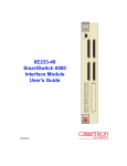
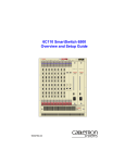
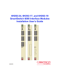
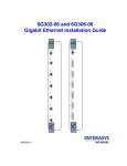
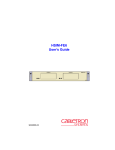
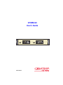
VHSIM-G6 User’s Guide VHSIM-G6 GPIM 1 9032549-03 GPIM 2 Only qualified personnel should perform installation procedures. NOTICE Cabletron Systems reserves the right to make changes in specifications and other information contained in this document without prior notice. The reader should in all cases consult Cabletron Systems to determine whether any such changes have been made. The hardware, firmware, or software described in this manual is subject to change without notice. IN NO EVENT SHALL CABLETRON SYSTEMS BE LIABLE FOR ANY INCIDENTAL, INDIRECT, SPECIAL, OR CONSEQUENTIAL DAMAGES WHATSOEVER (INCLUDING BUT NOT LIMITED TO LOST PROFITS) ARISING OUT OF OR RELATED TO THIS MANUAL OR THE INFORMATION CONTAINED IN IT, EVEN IF CABLETRON SYSTEMS HAS BEEN ADVISED OF, KNOWN, OR SHOULD HAVE KNOWN, THE POSSIBILITY OF SUCH DAMAGES. Cabletron Systems, Inc. 35 Industrial Way Rochester, NH 03867 1999 by Cabletron Systems, Inc. All Rights Reserved Printed in the United States of America Order Number: 9032549-03 June 1999 Cabletron Systems, SPECTRUM, and LANVIEW are registered trademarks and SmartSwitch is a trademark of Cabletron Systems, Inc. All other product names mentioned in this manual may be trademarks or registered trademarks of their respective companies. FCC NOTICE This device complies with Part 15 of the FCC rules. Operation is subject to the following two conditions: (1) this device may not cause harmful interference, and (2) this device must accept any interference received, including interference that may cause undesired operation. NOTE: This equipment has been tested and found to comply with the limits for a Class A digital device, pursuant to Part 15 of the FCC rules. These limits are designed to provide reasonable protection against harmful interference when the equipment is operated in a commercial environment. This equipment uses, generates, and can radiate radio frequency energy and if not installed in accordance with the operator’s manual, may cause harmful interference to radio communications. Operation of this equipment in a residential area is likely to cause interference in which case the user will be required to correct the interference at his own expense. WARNING: Changes or modifications made to this device which are not expressly approved by the party responsible for compliance could void the user’s authority to operate the equipment. VHSIM-G6 User’s Guide i Notice INDUSTRY CANADA NOTICE This digital apparatus does not exceed the Class A limits for radio noise emissions from digital apparatus set out in the Radio Interference Regulations of the Canadian Department of Communications. Le présent appareil numérique n’émet pas de bruits radioélectriques dépassant les limites applicables aux appareils numériques de la class A prescrites dans le Règlement sur le brouillage radioélectrique édicté par le ministère des Communications du Canada. VCCI NOTICE This is a Class A product based on the standard of the Voluntary Control Council for Interference by Information Technology Equipment (VCCI). If this equipment is used in a domestic environment, radio disturbance may arise. When such trouble occurs, the user may be required to take corrective actions. ii VHSIM-G6 User’s Guide Notice CABLETRON SYSTEMS, INC. PROGRAM LICENSE AGREEMENT IMPORTANT: THIS LICENSE APPLIES FOR USE OF PRODUCT IN THE FOLLOWING GEOGRAPHICAL REGIONS: CANADA MEXICO CENTRAL AMERICA SOUTH AMERICA BEFORE OPENING OR UTILIZING THE ENCLOSED PRODUCT, CAREFULLY READ THIS LICENSE AGREEMENT. This document is an agreement (“Agreement”) between You, the end user, and Cabletron Systems, Inc. (“Cabletron”) that sets forth your rights and obligations with respect to the Cabletron software program (“Program”) in the package. The Program may be contained in firmware, chips or other media. UTILIZING THE ENCLOSED PRODUCT, YOU ARE AGREEING TO BECOME BOUND BY THE TERMS OF THIS AGREEMENT, WHICH INCLUDES THE LICENSE AND THE LIMITATION OF WARRANTY AND DISCLAIMER OF LIABILITY. IF YOU DO NOT AGREE TO THE TERMS OF THIS AGREEMENT, RETURN THE UNOPENED PRODUCT TO CABLETRON OR YOUR DEALER, IF ANY, WITHIN TEN (10) DAYS FOLLOWING THE DATE OF RECEIPT FOR A FULL REFUND. IF YOU HAVE ANY QUESTIONS ABOUT THIS AGREEMENT, CONTACT CABLETRON SYSTEMS +1-603-332-9400. Attn: Legal Department. 1. LICENSE. You have the right to use only the one (1) copy of the Program provided in this package subject to the terms and conditions of this License Agreement. You may not copy, reproduce or transmit any part of the Program except as permitted by the Copyright Act of the United States or as authorized in writing by Cabletron. 2. OTHER RESTRICTIONS. You may not reverse engineer, decompile, or disassemble the Program. 3. APPLICABLE LAW. This License Agreement shall be interpreted and governed under the laws and in the state and federal courts of New Hampshire. You accept the personal jurisdiction and venue of the New Hampshire courts. 4. EXPORT REQUIREMENTS. You understand that Cabletron and its Affiliates are subject to regulation by agencies of the U.S. Government, including the U.S. Department of Commerce, which prohibit export or diversion of certain technical products to certain countries, unless a license to export the product is obtained from the U.S. Government or an exception from obtaining such license may be relied upon by the exporting party. If the Program is exported from the United States pursuant to the License Exception CIV under the U.S. Export Administration Regulations, You agree that You are a civil end user of the Program and agree that You will use the Program for civil end uses only and not for military purposes. VHSIM-G6 User’s Guide iii Notice If the Program is exported from the United States pursuant to the License Exception TSR under the U.S. Export Administration Regulations, in addition to the restriction on transfer set forth in Sections 1 or 2 of this Agreement, You agree not to (i) reexport or release the Program, the source code for the Program or technology to a national of a country in Country Groups D:1 or E:2 (Albania, Armenia, Azerbaijan, Belarus, Bulgaria, Cambodia, Cuba, Estonia, Georgia, Iraq, Kazakhstan, Kyrgyzstan, Laos, Latvia, Libya, Lithuania, Moldova, North Korea, the People’s Republic of China, Romania, Russia, Rwanda, Tajikistan, Turkmenistan, Ukraine, Uzbekistan, Vietnam, or such other countries as may be designated by the United States Government), (ii) export to Country Groups D:1 or E:2 (as defined herein) the direct product of the Program or the technology, if such foreign produced direct product is subject to national security controls as identified on the U.S. Commerce Control List, or (iii) if the direct product of the technology is a complete plant o r any major component of a plant, export to Country Groups D:1 or E:2 the direct product of the plant or a major component thereof, if such foreign produced direct product is subject to national security controls as identified on the U.S. Commerce Control List or is subject to State Department controls under the U.S. Munitions List. 5. UNITED STATES GOVERNMENT RESTRICTED RIGHTS. The enclosed Product (i) was developed solely at private expense; (ii) contains “restricted computer software” submitted with restricted rights in accordance with section 52.227-19 (a) through (d) of the Commercial Computer Software-Restricted Rights Clause and its successors, and (iii) in all respects is proprietary data belonging to Cabletron and/or its suppliers. For Department of Defense units, the Product is considered commercial computer software in accordance with DFARS section 227.7202-3 and its successors, and use, duplication, or disclosure by the Government is subject to restrictions set forth herein. 6. EXCLUSION OF WARRANTY. Except as may be specifically provided by Cabletron in writing, Cabletron makes no warranty, expressed or implied, concerning the Program (including its documentation and media). CABLETRON DISCLAIMS ALL WARRANTIES, OTHER THAN THOSE SUPPLIED TO YOU BY CABLETRON IN WRITING, EITHER EXPRESS OR IMPLIED, INCLUDING BUT NOT LIMITED TO IMPLIED WARRANTIES OF MERCHANTABILITY AND FITNESS FOR A PARTICULAR PURPOSE, WITH RESPECT TO THE PROGRAM, THE ACCOMPANYING WRITTEN MATERIALS, AND ANY ACCOMPANYING HARDWARE. 7. NO LIABILITY FOR CONSEQUENTIAL DAMAGES. IN NO EVENT SHALL CABLETRON OR ITS SUPPLIERS BE LIABLE FOR ANY DAMAGES WHATSOEVER (INCLUDING, WITHOUT LIMITATION, DAMAGES FOR LOSS OF BUSINESS, PROFITS, BUSINESS INTERRUPTION, LOSS OF BUSINESS INFORMATION, SPECIAL, INCIDENTAL, CONSEQUENTIAL, OR RELIANCE DAMAGES, OR OTHER LOSS) ARISING OUT OF THE USE OR INABILITY TO USE THIS CABLETRON PRODUCT, EVEN IF CABLETRON HAS BEEN ADVISED OF THE POSSIBILITY OF SUCH DAMAGES. BECAUSE SOME STATES DO NOT ALLOW THE EXCLUSION OR LIMITATION OF LIABILITY FOR CONSEQUENTIAL OR INCIDENTAL DAMAGES, OR IN THE DURATION OR LIMITATION OF IMPLIED WARRANTIES IN SOME INSTANCES, THE ABOVE LIMITATION AND EXCLUSIONS MAY NOT APPLY TO YOU. iv VHSIM-G6 User’s Guide Notice CABLETRON SYSTEMS SALES AND SERVICE, INC. PROGRAM LICENSE AGREEMENT IMPORTANT: THIS LICENSE APPLIES FOR USE OF PRODUCT IN THE UNITED STATES OF AMERICA AND BY UNITED STATES OF AMERICA GOVERNMENT END USERS. BEFORE OPENING OR UTILIZING THE ENCLOSED PRODUCT, CAREFULLY READ THIS LICENSE AGREEMENT. This document is an agreement (“Agreement”) between You, the end user, and Cabletron Systems Sales and Service, Inc. (“Cabletron”) that sets forth your rights and obligations with respect to the Cabletron software program (“Program”) in the package. The Program may be contained in firmware, chips or other media. UTILIZING THE ENCLOSED PRODUCT, YOU ARE AGREEING TO BECOME BOUND BY THE TERMS OF THIS AGREEMENT, WHICH INCLUDES THE LICENSE AND THE LIMITATION OF WARRANTY AND DISCLAIMER OF LIABILITY. IF YOU DO NOT AGREE TO THE TERMS OF THIS AGREEMENT, RETURN THE UNOPENED PRODUCT TO CABLETRON OR YOUR DEALER, IF ANY, WITHIN TEN (10) DAYS FOLLOWING THE DATE OF RECEIPT FOR A FULL REFUND. IF YOU HAVE ANY QUESTIONS ABOUT THIS AGREEMENT, CONTACT CABLETRON SYSTEMS +1-603-332-9400. Attn: Legal Department. 1. LICENSE. You have the right to use only the one (1) copy of the Program provided in this package subject to the terms and conditions of this License Agreement. You may not copy, reproduce or transmit any part of the Program except as permitted by the Copyright Act of the United States or as authorized in writing by Cabletron. 2. OTHER RESTRICTIONS. You may not reverse engineer, decompile, or disassemble the Program. 3. APPLICABLE LAW. This License Agreement shall be interpreted and governed under the laws and in the state and federal courts of New Hampshire. You accept the personal jurisdiction and venue of the New Hampshire courts. 4. EXPORT REQUIREMENTS. You understand that Cabletron and its Affiliates are subject to regulation by agencies of the U.S. Government, including the U.S. Department of Commerce, which prohibit export or diversion of certain technical products to certain countries, unless a license to export the product is obtained from the U.S. Government or an exception from obtaining such license may be relied upon by the exporting party. If the Program is exported from the United States pursuant to the License Exception CIV under the U.S. Export Administration Regulations, You agree that You are a civil end user of the Program and agree that You will use the Program for civil end uses only and not for military purposes. VHSIM-G6 User’s Guide v Notice If the Program is exported from the United States pursuant to the License Exception TSR under the U.S. Export Administration Regulations, in addition to the restriction on transfer set forth in Sections 1 or 2 of this Agreement, You agree not to (i) reexport or release the Program, the source code for the Program or technology to a national of a country in Country Groups D:1 or E:2 (Albania, Armenia, Azerbaijan, Belarus, Bulgaria, Cambodia, Cuba, Estonia, Georgia, Iraq, Kazakhstan, Kyrgyzstan, Laos, Latvia, Libya, Lithuania, Moldova, North Korea, the People’s Republic of China, Romania, Russia, Rwanda, Tajikistan, Turkmenistan, Ukraine, Uzbekistan, Vietnam, or such other countries as may be designated by the United States Government), (ii) export to Country Groups D:1 or E:2 (as defined herein) the direct product of the Program or the technology, if such foreign produced direct product is subject to national security controls as identified on the U.S. Commerce Control List, or (iii) if the direct product of the technology is a complete plant o r any major component of a plant, export to Country Groups D:1 or E:2 the direct product of the plant or a major component thereof, if such foreign produced direct product is subject to national security controls as identified on the U.S. Commerce Control List or is subject to State Department controls under the U.S. Munitions List. 5. UNITED STATES GOVERNMENT RESTRICTED RIGHTS. The enclosed Product (i) was developed solely at private expense; (ii) contains “restricted computer software” submitted with restricted rights in accordance with section 52.227-19 (a) through (d) of the Commercial Computer Software-Restricted Rights Clause and its successors, and (iii) in all respects is proprietary data belonging to Cabletron and/or its suppliers. For Department of Defense units, the Product is considered commercial computer software in accordance with DFARS section 227.7202-3 and its successors, and use, duplication, or disclosure by the Government is subject to restrictions set forth herein. 6. EXCLUSION OF WARRANTY. Except as may be specifically provided by Cabletron in writing, Cabletron makes no warranty, expressed or implied, concerning the Program (including its documentation and media). CABLETRON DISCLAIMS ALL WARRANTIES, OTHER THAN THOSE SUPPLIED TO YOU BY CABLETRON IN WRITING, EITHER EXPRESS OR IMPLIED, INCLUDING BUT NOT LIMITED TO IMPLIED WARRANTIES OF MERCHANTABILITY AND FITNESS FOR A PARTICULAR PURPOSE, WITH RESPECT TO THE PROGRAM, THE ACCOMPANYING WRITTEN MATERIALS, AND ANY ACCOMPANYING HARDWARE. 7. NO LIABILITY FOR CONSEQUENTIAL DAMAGES. IN NO EVENT SHALL CABLETRON OR ITS SUPPLIERS BE LIABLE FOR ANY DAMAGES WHATSOEVER (INCLUDING, WITHOUT LIMITATION, DAMAGES FOR LOSS OF BUSINESS, PROFITS, BUSINESS INTERRUPTION, LOSS OF BUSINESS INFORMATION, SPECIAL, INCIDENTAL, CONSEQUENTIAL, OR RELIANCE DAMAGES, OR OTHER LOSS) ARISING OUT OF THE USE OR INABILITY TO USE THIS CABLETRON PRODUCT, EVEN IF CABLETRON HAS BEEN ADVISED OF THE POSSIBILITY OF SUCH DAMAGES. BECAUSE SOME STATES DO NOT ALLOW THE EXCLUSION OR LIMITATION OF LIABILITY FOR CONSEQUENTIAL OR INCIDENTAL DAMAGES, OR IN THE DURATION OR LIMITATION OF IMPLIED WARRANTIES IN SOME INSTANCES, THE ABOVE LIMITATION AND EXCLUSIONS MAY NOT APPLY TO YOU. vi VHSIM-G6 User’s Guide Notice CABLETRON SYSTEMS LIMITED PROGRAM LICENSE AGREEMENT IMPORTANT: THIS LICENSE APPLIES FOR THE USE OF THE PRODUCT IN THE FOLLOWING GEOGRAPHICAL REGIONS: EUROPE MIDDLE EAST AFRICA ASIA AUSTRALIA PACIFIC RIM BEFORE OPENING OR UTILIZING THE ENCLOSED PRODUCT, CAREFULLY READ THIS LICENSE AGREEMENT. This document is an agreement (“Agreement”) between You, the end user, and Cabletron Systems Limited (“Cabletron”) that sets forth your rights and obligations with respect to the Cabletron software program (“Program”) in the package. The Program may be contained in firmware, chips or other media. UTILIZING THE ENCLOSED PRODUCT, YOU ARE AGREEING TO BECOME BOUND BY THE TERMS OF THIS AGREEMENT, WHICH INCLUDES THE LICENSE AND THE LIMITATION OF WARRANTY AND DISCLAIMER OF LIABILITY. IF YOU DO NOT AGREE TO THE TERMS OF THIS AGREEMENT, RETURN THE UNOPENED PRODUCT TO CABLETRON OR YOUR DEALER, IF ANY, WITHIN TEN (10) DAYS FOLLOWING THE DATE OF RECEIPT FOR A FULL REFUND. IF YOU HAVE ANY QUESTIONS ABOUT THIS AGREEMENT, CONTACT CABLETRON SYSTEMS +1-603-332-9400. Attn: Legal Department. 1. LICENSE. You have the right to use only the one (1) copy of the Program provided in this package subject to the terms and conditions of this License Agreement. You may not copy, reproduce or transmit any part of the Program except as permitted by the Copyright Act of the United States or as authorized in writing by Cabletron. 2. OTHER RESTRICTIONS. You may not reverse engineer, decompile, or disassemble the Program. 3. APPLICABLE LAW. This License Agreement shall be governed in accordance with English law. The English courts shall have exclusive jurisdiction in the event of any disputes. 4. EXPORT REQUIREMENTS. You understand that Cabletron and its Affiliates are subject to regulation by agencies of the U.S. Government, including the U.S. Department of Commerce, which prohibit export or diversion of certain technical products to certain countries, unless a license to export the product is obtained from the U.S. Government or an exception from obtaining such license may be relied upon by the exporting party. If the Program is exported from the United States pursuant to the License Exception CIV under the U.S. Export Administration Regulations, You agree that You are a civil end user of the Program and agree that You will use the Program for civil end uses only and not for military purposes. VHSIM-G6 User’s Guide vii Notice If the Program is exported from the United States pursuant to the License Exception TSR under the U.S. Export Administration Regulations, in addition to the restriction on transfer set forth in Sections 1 or 2 of this Agreement, You agree not to (i) reexport or release the Program, the source code for the Program or technology to a national of a country in Country Groups D:1 or E:2 (Albania, Armenia, Azerbaijan, Belarus, Bulgaria, Cambodia, Cuba, Estonia, Georgia, Iraq, Kazakhstan, Kyrgyzstan, Laos, Latvia, Libya, Lithuania, Moldova, North Korea, the People’s Republic of China, Romania, Russia, Rwanda, Tajikistan, Turkmenistan, Ukraine, Uzbekistan, Vietnam, or such other countries as may be designated by the United States Government), (ii) export to Country Groups D:1 or E:2 (as defined herein) the direct product of the Program or the technology, if such foreign produced direct product is subject to national security controls as identified on the U.S. Commerce Control List, or (iii) if the direct product of the technology is a complete plant o r any major component of a plant, export to Country Groups D:1 or E:2 the direct product of the plant or a major component thereof, if such foreign produced direct product is subject to national security controls as identified on the U.S. Commerce Control List or is subject to State Department controls under the U.S. Munitions List. 5. UNITED STATES GOVERNMENT RESTRICTED RIGHTS. The enclosed Product (i) was developed solely at private expense; (ii) contains “restricted computer software” submitted with restricted rights in accordance with section 52.227-19 (a) through (d) of the Commercial Computer Software-Restricted Rights Clause and its successors, and (iii) in all respects is proprietary data belonging to Cabletron and/or its suppliers. For Department of Defense units, the Product is considered commercial computer software in accordance with DFARS section 227.7202-3 and its successors, and use, duplication, or disclosure by the Government is subject to restrictions set forth herein. 6. EXCLUSION OF WARRANTY. Except as may be specifically provided by Cabletron in writing, Cabletron makes no warranty, expressed or implied, concerning the Program (including its documentation and media). CABLETRON DISCLAIMS ALL WARRANTIES, OTHER THAN THOSE SUPPLIED TO YOU BY CABLETRON IN WRITING, EITHER EXPRESS OR IMPLIED, INCLUDING BUT NOT LIMITED TO IMPLIED WARRANTIES OF MERCHANTABILITY AND FITNESS FOR A PARTICULAR PURPOSE, WITH RESPECT TO THE PROGRAM, THE ACCOMPANYING WRITTEN MATERIALS, AND ANY ACCOMPANYING HARDWARE. 7. NO LIABILITY FOR CONSEQUENTIAL DAMAGES. IN NO EVENT SHALL CABLETRON OR ITS SUPPLIERS BE LIABLE FOR ANY DAMAGES WHATSOEVER (INCLUDING, WITHOUT LIMITATION, DAMAGES FOR LOSS OF BUSINESS, PROFITS, BUSINESS INTERRUPTION, LOSS OF BUSINESS INFORMATION, SPECIAL, INCIDENTAL, CONSEQUENTIAL, OR RELIANCE DAMAGES, OR OTHER LOSS) ARISING OUT OF THE USE OR INABILITY TO USE THIS CABLETRON PRODUCT, EVEN IF CABLETRON HAS BEEN ADVISED OF THE POSSIBILITY OF SUCH DAMAGES. BECAUSE SOME STATES DO NOT ALLOW THE EXCLUSION OR LIMITATION OF LIABILITY FOR CONSEQUENTIAL OR INCIDENTAL DAMAGES, OR IN THE DURATION OR LIMITATION OF IMPLIED WARRANTIES IN SOME INSTANCES, THE ABOVE LIMITATION AND EXCLUSIONS MAY NOT APPLY TO YOU. viii VHSIM-G6 User’s Guide Notice SAFETY INFORMATION CLASS 1 LASER TRANSCEIVERS THE GPIM-01 AND GPIM-09 GIGABIT ETHERNET INTERFACE MODULES USE CLASS 1 LASER TRANSCEIVERS. READ THE FOLLOWING SAFETY INFORMATION BEFORE INSTALLING OR OPERATING THESE MODULES. The Class 1 laser transceivers use an optical feedback loop to maintain Class 1 operation limits. This control loop eliminates the need for maintenance checks or adjustments. The output is factory set, and does not allow any user adjustment. Class 1 Laser transceivers comply with the following safety standards: • 21 CFR 1040.10 and 1040.11 U.S. Department of Health and Human Services (FDA). • IEC Publication 825 (International Electrotechnical Commission). • CENELEC EN 60825 (European Committee for Electrotechnical Standardization). When operating within their performance limitations, laser transceiver output meets the Class 1 accessible emission limit of all three standards. Class 1 levels of laser radiation are not considered hazardous. SAFETY INFORMATION CLASS 1 LASER TRANSCEIVERS LASER RADIATION AND CONNECTORS When the connector is in place, all laser radiation remains within the fiber. The maximum amount of radiant power exiting the fiber (under normal conditions) is -12.6 dBm or 55 x 10-6 watts. Removing the optical connector from the transceiver allows laser radiation to emit directly from the optical port. The maximum radiance from the optical port (under worst case conditions) is 0.8 W cm-2 or 8 x 10³ W m2 sr-1. Do not use optical instruments to view the laser output. The use of optical instruments to view laser output increases eye hazard. When viewing the output optical port, power must be removed from the network adapter. VHSIM-G6 User’s Guide ix Notice DECLARATION OF CONFORMITY Application of Council Directive(s): Manufacturer’s Name: Manufacturer’s Address: European Representative Name: European Representative Address: Conformance to Directive(s)/Product Standards: Equipment Type/Environment: 89/336/EEC 73/23/EEC Cabletron Systems, Inc. 35 Industrial Way PO Box 5005 Rochester, NH 03867 Mr. J. Solari Cabletron Systems Limited Nexus House, Newbury Business Park London Road, Newbury Berkshire RG14 2PZ, England EC Directive 89/336/EEC EC Directive 73/23/EEC EN 55022 EN 50082-1 EN 60950 Networking Equipment, for use in a Commercial or Light Industrial Environment. We the undersigned, hereby declare, under our sole responsibility, that the equipment packaged with this notice conforms to the above directives. Manufacturer Legal Representative in Europe Mr. Ronald Fotino ___________________________________ Full Name Mr. J. Solari ___________________________________ Full Name Compliance Engineering Manager ___________________________________ Title Managing Director - E.M.E.A. ___________________________________ Title Rochester, NH, USA ___________________________________ Location Newbury, Berkshire, England ___________________________________ Location x VHSIM-G6 User’s Guide CONTENTS FIGURES ............................................................................................... xiii TABLES ................................................................................................. xiv CHAPTER 1 INTRODUCTION 1.1 Structure of this Guide................................................................. 1-2 1.2 Overview...................................................................................... 1-2 1.2.1 Connectivity .................................................................... 1-3 1.2.2 LANVIEW Diagnostic LEDs ............................................ 1-3 1.2.3 Options ........................................................................... 1-3 1.3 Document Conventions ............................................................... 1-4 1.4 Related Documentation ............................................................... 1-4 1.5 Getting Help................................................................................. 1-5 CHAPTER 2 INSTALLATION 2.1 Unpacking the VHSIM-G6 ........................................................... 2-1 2.2 Installing the VHSIM-G6 .............................................................. 2-2 2.2.1 Installing the VHSIM-G6 in an Interface Module............. 2-2 2.2.2 Installing the VHSIM-G6 in a Standalone Device ........... 2-5 2.3 Installing GPIMs .......................................................................... 2-6 2.4 GPIM-01 and GPIM-09 Network Connections............................. 2-8 2.4.1 GPIM-09 Connection Using Multimode Cable ................ 2-9 2.4.2 VHSIM-G6 Network Connection ................................... 2-10 CHAPTER 3 LANVIEW LEDs 3.1 LED Descriptions......................................................................... 3-1 3.2 Redundancy ................................................................................ 3-2 CHAPTER 4 LOCAL MANAGEMENT 4.1 Requirements .............................................................................. 4-1 4.2 Gigabit Port Mode........................................................................ 4-1 VHSIM-G6 User’s Guide xi Contents APPENDIX A VHSIM-G6 SPECIFICATIONS A.1 Physical and Environmental Specifications ................................ A-1 A.2 Regulatory Compliance............................................................... A-1 APPENDIX B GPIM SPECIFICATIONS B.1 Gigabit Ethernet Specifications................................................... B-1 B.1.1 GPIM-01 Specifications (1000Base-SX)......................... B-1 B.1.2 GPIM-09 Specifications (1000Base-LX) ......................... B-2 B.2 Physical and Environmental Specifications ................................ B-3 B.3 Regulatory Compliance............................................................... B-3 xii VHSIM-G6 User’s Guide FIGURES Figure 1-1 2-1 2-2 2-3 2-4 2-5 2-6 2-7 2-8 3-1 Page VHSIM-G6 (shown with fiber GPIMs)....................................... 1-1 Removing the VHSIM Coverplate from the Host Device.......... 2-3 Installing the VHSIM-G6 in the Host Device............................. 2-4 GPIM ........................................................................................ 2-7 Installing a GPIM into the VHSIM-G6....................................... 2-8 VHSIM-G6 Fiber Port Designations ......................................... 2-8 GPIM-09 Launch Mode Conditioning Cable Connection........ 2-10 Fiber GPIM Connections ........................................................ 2-11 VHSIM-G6 with Two Fiber Ports ............................................ 2-12 LANVIEW LEDs on the VHSIM-G6 .......................................... 3-1 VHSIM-G6 User’s Guide xiii TABLES Table 1-1 3-1 A-1 A-2 A-3 B-2 B-1 B-4 B-3 B-5 B-6 B-7 Page GPIM Options........................................................................... 1-3 VHSIM-G6 LED Functionality................................................... 3-2 Physical Properties of the VHSIM-G6 ......................................A-1 Environmental Requirements of the VHSIM-G6.......................A-1 Regulatory Compliance of the VHSIM-G6................................A-1 GPIM-01 Operating Range.......................................................B-1 GPIM-01 Optical Specifications................................................B-1 GPIM-09 Operating Range.......................................................B-2 GPIM-09 Optical Specifications................................................B-2 GPIM Physical Properties ........................................................B-3 GPIM Environmental Requirements.........................................B-3 Regulatory Compliance ............................................................B-3 VHSIM-G6 User’s Guide xiv CHAPTER 1 INTRODUCTION Welcome to the Cabletron Systems VHSIM-G6 User’s Guide. This manual describes the VHSIM-G6 and provides information concerning features, installation, troubleshooting, information on Local Management, and specifications for the VHSIM-G6 (Very High Speed Interface Module). A general working knowledge of Gigabit Ethernet and IEEE 802.3z type data communications networks and their physical layer components is helpful when installing the VHSIM-G6. The VHSIM-G6 (Figure 1-1) has two Gigabit Ethernet Port Interface Module (GPIM) ports that provide Gigabit Ethernet connections. The GPIMs are hot swappable, allowing the user to reconfigure the VHSIM-G6 when it is installed and the host platform has power applied to it. There are two modes of operation for the VHSIM-G6. In one mode, both GPIM ports are active at the same time. In the other mode, one port is active and the other is redundant, where redundancy is triggered based on link activity, and GPIM 1 is the active port by default. The default mode for the VHSIM-G6 is redundancy. GPIM 1 GPIM 2 GPIM Ports Figure 1-1 NOTE VHSIM-G6 2549_01 VHSIM-G6 (shown with fiber GPIMs) The acronym “GPIM” stands for Gigabit (Ethernet) Port Interface Module. In this manual, GPIM is used to designate any type of GPIM. When referring to a specific GPIM, the specific name is used, e.g., GPIM-01. The term “host platform” may be used to refer to the module or standalone device in which the VHSIM-G6 may be installed. VHSIM-G6 User’s Guide 1-1 Chapter 1: Introduction 1.1 STRUCTURE OF THIS GUIDE Read through this manual completely to familiarize yourself with its content and to gain an understanding of the features and capabilities of the VHSIM-G6. The following list provides an overview of each section of this manual: Chapter 1, Introduction, outlines the contents of this manual, describes the VHSIM-G6 features and concludes with a web site address where related manuals can be obtained. Chapter 2, Installation, describes how to install a VHSIM-G6 into an interface module or a standalone device. Chapter 3, LANVIEW LEDs, describes how to use the VHSIM-G6 LEDs to monitor performance and status. Chapter 4, Local Management, gives information on Local Management for the VHSIM-G6. Appendix A, VHSIM-G6 Specifications, lists the operating specifications and regulatory compliance for the VHSIM-G6. Appendix B, GPIM Specifications, lists the operating specifications and regulatory compliance for the GPIMs. 1.2 OVERVIEW The VHSIM-G6 has two ports that support Gigabit Ethernet Port Interface Modules (GPIMs), which allow the user to make fiber connections to Gigabit Ethernet networks. Available GPIMs include the GPIM-01, for multimode fiber support, and the GPIM-09, for multimode or single mode fiber support. The VHSIM-G6 extends the functionality of various Cabletron Systems interface modules or standalone devices by providing high-speed uplink capability through Gigabit Ethernet technology. VHSIM-G6 features include the following: • Customized configuration of GPIMs • RMON support (Statistics, History, Alarms, Events) • Management • Flow control (802.3z) 1-2 VHSIM-G6 User’s Guide Overview 1.2.1 Connectivity The VHSIM-G6 supports two modes of operation for the Gigabit interfaces. One mode is that the VHSIM-G6 supports one active and one redundant Gigabit Ethernet Interface Module (GPIM). The other mode is that both of the interfaces can be active at the same time. The VHSIM-G6 supports the interfaces with two different hot-swappable GPIMs, providing connectivity to Gigabit Ethernet using fiber. Any combination of GPIMs can be installed in the two VHSIM-G6 ports. The VHSIM-G6 module supports the 1000Base-SX and 1000Base-LX specifications using the GPIMs. 1000Base-SX is supported with the GPIM-01 providing one SC fiber optic connector for 50 or 62.5 micron multimode fiber optic cable. 1000Base-LX is supported with the GPIM-09 providing one SC fiber optic connector for 50 or 62.5 micron multimode fiber optic cable, or 10 micron single mode fiber optic cable. For more specifications on GPIMs, see Appendix B. The VHSIM-G6 operates in full duplex mode, and follows the 802.3x specifications for auto-negotiation. 1.2.2 LANVIEW Diagnostic LEDs Cabletron Systems provides a visual diagnostic and monitoring system called LANVIEW. The VHSIM-G6 LANVIEW LEDs help you quickly identify transmit, receive, and link status. Chapter 3 provides information on the VHSIM-G6 LEDs. 1.2.3 Options The options for the VHSIM-G6 are GPIMs, as listed in Table 1-1. Table 1-1 GPIM Options Part Number Description Application GPIM-01 SC fiber connector Supports 50 or 62.5 micron multimode fiber. GPIM-09 SC fiber connector Supports single mode (10 micron) or multimode (50 or 62.5 micron) fiber. VHSIM-G6 User’s Guide 1-3 Chapter 1: Introduction 1.3 DOCUMENT CONVENTIONS The following conventions are used throughout this document: NOTE ! Note symbol. Calls the reader’s attention to any item of information that may be of special importance. Caution symbol. Contains information essential to avoid damage to the equipment. CAUTION Electrical Hazard Warning symbol. Warns against an action that could result in personal injury or death due to an electrical hazard. 1.4 RELATED DOCUMENTATION The documentation for the host platform in which the VHSIM-G6 is to be installed, whether standalone device or module, provides additional information about the setup of the VHSIM-G6. This user’s guide references procedures in these documents, where appropriate, but does not repeat them. Documents can be obtained on the World Wide Web in Adobe Acrobat Portable Document Format (PDF) at the following site: http://www.cabletron.com/ 1-4 VHSIM-G6 User’s Guide Getting Help 1.5 GETTING HELP For additional support related to this device or document, contact Cabletron Systems using one the following methods. World Wide Web http://www.cabletron.com/ Phone (603) 332-9400 Internet mail [email protected] FTP ftp://ftp.cabletron.com/ anonymous your email address Login Password To send comments or suggestions concerning this document, contact the Cabletron Systems Technical Writing Department via the following email address: [email protected] Make sure to include the document Part Number in the email message. Before calling Cabletron Systems, have the following information ready: • Your Cabletron Systems service contract number • A description of the failure • A description of any action(s) already taken to resolve the problem (e.g., changing mode switches, rebooting the unit, etc.) • The serial and revision numbers of all involved Cabletron Systems products in the network • A description of your network environment (layout, cable type, etc.) • Network load and frame size at the time of trouble (if known) • The device history (i.e., have you returned the device before, is this a recurring problem, etc.) • Any previous Return Material Authorization (RMA) numbers VHSIM-G6 User’s Guide 1-5 Chapter 1: Introduction 1-6 VHSIM-G6 User’s Guide CHAPTER 2 INSTALLATION Only qualified personnel should install or service this unit. To install the VHSIM-G6 you need the following items: • Phillips screwdriver • Antistatic wrist strap (shipped with the VHSIM-G6) • Standoff screws (shipped with the VHSIM-G6) NOTE 2.1 Before attempting to use the VHSIM-G6 you should be familiar with the IEEE 802.3z specification. The network installation must meet the guidelines contained in the draft specification to ensure satisfactory performance. UNPACKING THE VHSIM-G6 ! CAUTION The VHSIM-G6 and the host module or device (platform) are sensitive to static discharges. Use an antistatic wrist strap and observe all static precautions during this procedure. Failure to do so could result in damage to the VHSIM-G6 or host platform. Unpack the VHSIM-G6 as follows: 1. Remove the VHSIM-G6 from the shipping box. Leave the module in the antistatic bag until you are ready to install it. 2. Attach the antistatic wrist strap. If the VHSIM-G6 is to be installed in a standalone device, refer to the instructions on the antistatic wrist strap package. If the VHSIM-G6 is to be installed in an interface module, refer to the applicable interface module User’s Guide. 3. After removing the VHSIM-G6 from the antistatic bag, visually inspect the device. If there is any sign of damage, contact Cabletron Systems immediately. Refer to Section 1.5 for instructions. Save the antistatic bag in the event the VHSIM-G6 must be reshipped. VHSIM-G6 User’s Guide 2-1 Chapter 2: Installation 2.2 INSTALLING THE VHSIM-G6 You can install a VHSIM-G6 in any Cabletron Systems device that supports VHSIM technology (e.g., 2E253-49R, 6H252-17). NOTE Refer to the release notes for the version of firmware running on the Cabletron Systems device to ensure that the VHSIM-G6 is supported. The following subsections provide instructions for installing a VHSIM-G6 in an interface module or in a standalone device. Refer to your specific interface module or standalone device documentation for exact VHSIM slot and connector locations. 2.2.1 Installing the VHSIM-G6 in an Interface Module To install a VHSIM-G6 in an interface module that supports VHSIM technology, perform the following steps: 1. Note the ports of the interface module that have cables attached to them. Write down the ports and label the cables to make it easier to reattach the network properly after the installation. Then disconnect the cables from the ports. 2. Attach the antistatic wrist strap (refer to the instructions outlined in the interface module User’s Guide). ! CAUTION The VHSIM-G6 and the host module are sensitive to static discharges. Use an antistatic wrist strap and observe all static precautions during this procedure. Failure to do so could result in damage to the VHSIM-G6 or host module. 3. If the module is installed in a chassis, unlock the top and bottom plastic locking tabs of the module faceplate, and remove the module from the chassis. 2-2 VHSIM-G6 User’s Guide Installing the VHSIM-G6 4. Lay the module down with the internal components facing up. 5. Refer to Figure 2-1 and remove the two faceplate mounting screws and the VHSIM coverplate. Save the screws. VHSIM Coverplate Faceplate Mounting Screws Host Platform 2549_03 Figure 2-1 Removing the VHSIM Coverplate from the Host Device VHSIM-G6 User’s Guide 2-3 Chapter 2: Installation 6. Refer to Figure 2-2 and position the VHSIM-G6 behind the module faceplate, above the connectors. Standoff Screws Connectors (top view) Connectors Cutaway view of connectors VHSIM-G6 GP IM 1 GP IM 2 VH SIM -G 6 Standoff SP Connectors Standoff Faceplate Mounting Screws Host Platform 2549_36 Figure 2-2 Installing the VHSIM-G6 in the Host Device 7. Align the VHSIM-G6 connectors with the VHSIM connectors on the module. ! CAUTION When installing the VHSIM-G6, ensure that the pins on the module align with the connector to prevent bending the pins. This can damage both the VHSIM-G6 and the module. 8. Press down firmly on the VHSIM-G6 until the connectors slide all the way onto the pins. Ensure that the standoffs on the interface module align with the standoff screw holes on the VHSIM-G6. 2-4 VHSIM-G6 User’s Guide Installing the VHSIM-G6 9. Secure the VHSIM-G6 to the module faceplate using the mounting screws saved in step 5. 10. Secure the VHSIM-G6 to the module standoffs using the standoff screws shipped with the VHSIM-G6. 11. Reinstall the interface module in the chassis. 12. Reattach the network cabling to the interface module. 2.2.2 Installing the VHSIM-G6 in a Standalone Device To install a VHSIM-G6 into a standalone device (e.g., 2H252-25R) that supports VHSIM technology, perform the following steps: 1. Power down the device and remove the power cord. 2. Note the ports that have cables attached to them. Write down the ports and label the cables to make it easier to reattach the network properly after the installation. Then disconnect the cables from the ports. To install the VHSIM-G6 in a standalone device, the device must first be powered down. Ensure that you remove the power cord and ONLY the screws required to remove the chassis cover. 3. Attach the antistatic wrist strap (refer to the instructions outlined on the antistatic wrist strap package). ! CAUTION The VHSIM-G6 and the device are sensitive to static discharges. Use an antistatic wrist strap and observe all static precautions during this procedure. Failure to do so could result in damage to the VHSIM-G6 or device. 4. Remove the standalone device chassis cover. Refer to your specific standalone device documentation for instructions on removing the chassis cover. 5. Refer back to Figure 2-1 and remove the two faceplate mounting screws and the VHSIM coverplate. Save the screws. 6. Refer back to Figure 2-2 and place the VHSIM-G6 module behind the standalone device faceplate. VHSIM-G6 User’s Guide 2-5 Chapter 2: Installation 7. Align the VHSIM-G6 connectors with the pins on the standalone device. ! CAUTION When inserting the VHSIM-G6 onto the device pins, ensure that the pins do not bend, as this can damage both the device and the VHSIM-G6. 8. Press down firmly on the VHSIM-G6 until the connectors slide all the way onto the pins. Ensure that the standoffs on the standalone device align with the standoff screw holes on the VHSIM-G6. 9. Secure the VHSIM-G6 to the module faceplate using the mounting screws saved in step 5. 10. Secure the VHSIM-G6 to the module standoffs using the standoff screws shipped with the VHSIM-G6. Ensure that the chassis cover is in place before reconnecting the power cord. 11. Reattach the chassis cover to the standalone device, reconnect the power cord, and reconnect the standalone device to the network. 2.3 INSTALLING GPIMs The VHSIM-G6 has two different GPIMs that can be installed into the VHSIM-G6. Both GPIMs are installed into the VHSIM-G6 in the same manner, as listed in this procedure. NOTE The GPIMs are hot swappable, therefore they can be installed into the VHSIM-G6 at any time during the installation of the VHSIM-G6. After installing a GPIM-01 or GPIM-09, refer to Section 2.4 for details on connecting the GPIM to the network. Refer to Appendix B for cable specifications for the GPIMs. 2-6 VHSIM-G6 User’s Guide Installing GPIMs ! CAUTION The GPIM, VHSIM-G6 and the host module or device are sensitive to static discharges. Use an antistatic wrist strap and observe all static precautions during this procedure. Failure to do so could result in damage to the GPIM, VHSIM-G6, or host module or device. Always leave the GPIM in the antistatic bag in which it was shipped or an equivalent antistatic container until ready to install it. The GPIMs are installed into the VHSIM-G6 as follows: 1. Attach the antistatic strap (refer to the instructions in the antistatic wrist strap package) before removing the GPIM from the antistatic packaging. 2. Remove the GPIM from the packaging. 3. Hold the GPIM with the network connection port facing away from the VHSIM-G6. The 20-pin connector should be facing towards the empty GPIM slot, with the wide part of the connector oriented up in relation to the printing on the VHSIM-G6. See Figure 2-3 to orient the GPIM 20-pin connector. X R Insertion End X T 20-pin connector Network Connection End Figure 2-3 2549_04 GPIM 4. Gently insert the GPIM (20-pin connector side) through the GPIM opening of the VHSIM-G6. See Figure 2-4. The door folds up and the slides engage the sides of the GPIM. If the GPIM does not go in easily, do not force the device. Check the orientation against Figure 2-3. Push the GPIM back until the 20-pin port engages the GPIM. The latch mechanism engages when the GPIM connector seats properly in the port. VHSIM-G6 User’s Guide 2-7 Chapter 2: Installation VHSIM-G6 GPIM 1 GPIM 2 R X T Locking Tab (hidden from view) X 20-pin Connector (insertion end) Locking Tab Network Port 2549_05 Figure 2-4 Installing a GPIM into the VHSIM-G6 To remove a GPIM from the VHSIM-G6, squeeze both locking tabs in towards the center of the GPIM, and pull it out of the port. 2.4 GPIM-01 AND GPIM-09 NETWORK CONNECTIONS The GPIM-01 and the GPIM-09 each have an SC style connector for the network port that is used to connect to the Gigabit Ethernet network. Cabletron Systems offers fiber optic cables that use SC style connectors which are keyed to ensure proper crossover of the transmit and receive fibers. GPIM 1 Receive (Rx) Transmit (Tx) Figure 2-5 2-8 VHSIM-G6 GPIM 2 Receive (Rx) Transmit (Tx) 2549_01 VHSIM-G6 Fiber Port Designations VHSIM-G6 User’s Guide GPIM-01 and GPIM-09 Network Connections Since the GPIM-01 and GPIM-09 both have the same type of SC fiber connector, the directions for connectivity are the same, except for when the GPIM-09 is connected to multimode fiber. Refer to Section 2.4.1 before connecting the GPIM-09 to multimode fiber. Different size and wavelength fiber cable is used for different applications. The GPIM-09 typically has a blue connector to indicate the long wave length transceiver. The GPIM-01 connector is typically black or beige, for multimode fiber cable. Check the fiber specifications in Appendix B for each GPIM carefully before connecting a GPIM to the network. NOTES An odd number of crossovers (preferably one) must be maintained between like devices so that the transmit port of one device is connected to the receive port of the other device and vice versa. If the fiber optic cable being used has SC style connectors that do not resemble MIC style connectors, or has SC connectors on one end and a different type on the other, such as ST connectors, ensure that the proper cable cross-over occurs. 2.4.1 NOTE GPIM-09 Connection Using Multimode Cable When using multimode fiber cable for the GPIM-09 (long wave length transceiver), connect Launch Mode Conditioning cable as detailed in the following procedure (Section 2.4.1). The following procedure is not needed when connecting single mode fiber cable to the GPIM-09. Launch Mode Conditioning cables are available from Cabletron Systems. To connect the GPIM-09 to the network using multimode fiber, perform the following steps: 1. Connect Launch Mode Conditioning cable to the multimode fiber on both ends of the multimode cable, before connecting the VHSIM-G6 with a GPIM-09 to the multimode fiber cabling. See Figure 2-6. VHSIM-G6 User’s Guide 2-9 Chapter 2: Installation Launch Mode Conditioning Cable Long Wavelength Gigabit Fiber Device Installed multimode fiber cable Launch Mode Conditioning Cable Connect the ends of the multimode cable to the Launch Mode Conditioning Cable Long Wavelength Gigabit Fiber Device mmfLWct Figure 2-6 GPIM-09 Launch Mode Conditioning Cable Connection 2. Once the Launch Mode Conditioning cable is connected to the ends of the multimode fiber cable, proceed to Section 2.4.2 to complete the installation to the GPIM-09 device. 2.4.2 VHSIM-G6 Network Connection To connect the VHSIM-G6 using fiber cable to the network, perform the following steps: NOTE If connecting the VHSIM-G6 with a GPIM-09 to the network using multimode fiber cable, refer to Section 2.4.1 before following this procedure. 1. Remove the protective covers from the fiber optic ports and from the ends of the connectors. ! CAUTION 2-10 The GPIM-01 and GPIM-09 use Class 1 lasers. Do not use optical instruments to view the laser output. The use of optical instruments to view laser output increases eye hazard. When viewing the output optical port, power must be removed from the network adapter. VHSIM-G6 User’s Guide GPIM-01 and GPIM-09 Network Connections NOTE Leave the protective covers in place when the connectors or ports are not in use to prevent contamination. Do not touch the ends of the fiber optic strands, and do not let the ends come in contact with dust, dirt, or other contaminants. Contamination of the ends causes problems in data transmission. If the ends become contaminated, blow the surfaces clean with a canned duster. A fiber port cleaning swab saturated with optical-grade isopropyl alcohol may also be used to clean the ends. 2. Insert one end of the SC connector, key side down, into the GPIM-01 or GPIM-09 in the VHSIM-G6. See Figure 2-7. Ensure that the appropriate cable is used for the application of the GPIM. Refer to Appendix B for the appropriate GPIM for the fiber cable used for the installation. VHSIM-G6 GPIM 1 GPIM 2 SP Key Latch (bottom of SC Connector) GPIM-01 or GPIM-09 SC Connector keys SC Connector (bottom view) SC_GBIC Figure 2-7 VHSIM-G6 User’s Guide Fiber GPIM Connections 2-11 Chapter 2: Installation 3. At the other end of the fiber optic cable, attach the SC connector to the other device. Verify that a link exists by checking that the port Receive LED is ON (flashing amber, blinking green, or solid green). Refer to Chapter 3 for details on the LEDs. If the Receive LED is OFF and the Transmit LED is not blinking amber, perform the following steps until it is ON: a. Check that the device at the other end of the link has power turned on and is Gigabit Ethernet compatible. b. Verify proper crossover of fiber strands between the port on the VHSIM-G6 and the fiber optic device at the other end of the fiber optic link segment. c. Verify that the fiber connection meets the specifications outlined in Appendix B for the installed GPIM. To remove the SC connector from the GPIM, carefully pull the connector out of the port. It may need to be wiggled gently to release the latching keys. VHSIM-G6 GPIM 1 Receive (RX) Transmit (TX) Figure 2-8 GPIM 2 Receive (RX) Transmit (TX) 2549_02 VHSIM-G6 with Two Fiber Ports Refer to Chapter 4 for information on Local Management for the VHSIM-G6. If a link has not been established, refer to Chapter 3 for LED troubleshooting details. Refer to Section 1.5 for details on contacting Cabletron Systems if a problem persists. 2-12 VHSIM-G6 User’s Guide CHAPTER 3 LANVIEW LEDs This chapter describes how to use the LANVIEW LEDs to monitor the VHSIM-G6 status and diagnose VHSIM-G6 problems. Figure 3-1 shows the location of the VHSIM-G6 LEDs. Refer to Table 3-1 for a description of the LEDs. Section 3.2 describes redundancy. This information applies to all types of installed GPIMs. 3.1 LED DESCRIPTIONS VHSIM-G6 GPIM 1 Receive (RX) Transmit (TX) Figure 3-1 NOTE GPIM 2 Receive (RX) Transmit (TX) 2549_02 LANVIEW LEDs on the VHSIM-G6 The terms flashing, blinking, and solid used in Table 3-1 indicate the following: Flashing indicates an irregular LED pulse. Blinking indicates a steady LED pulse (approximately 50% on and 50% off). Solid indicates a steady LED light. No pulsing. VHSIM-G6 User’s Guide 3-1 Chapter 3: LANVIEW LEDs Table 3-1 LED Transmit Receive 3.2 VHSIM-G6 LED Functionality Color Definition Green (Flashing) Activity, port enabled. Amber (Blinking) Port in standby. Off No activity, port enabled. Red (Flashing) Transmit fault. Red Diagnostic failure. Green (Solid) Link, no activity. Port enabled. Green (Blinking) Link, port disabled. Amber (Flashing) Link, activity. Port enabled. Off No link, no activity. Port enabled or disabled. Red Diagnostic failure. REDUNDANCY The VHSIM-G6 supports two modes of operation with the Gigabit interfaces. Both the interfaces can be active, or one can be active and the other redundant. When both interfaces are active, all led descriptions will apply to both ports. In the redundancy mode, only one of the two ports on the VHSIM-G6 is active at one time. The port with link status showing (either a green LED, solid or blinking, or an amber LED) is the active port. If both ports show a link, GPIM 1 is the active port. The default port for the primary port link is GPIM 1. 3-2 VHSIM-G6 User’s Guide CHAPTER 4 LOCAL MANAGEMENT This chapter provides information about using Local Management with the VHSIM-G6. Since the VHSIM-G6 is a Gigabit Ethernet device, the Local Management screens used for configuration and statistics are the same as those of the host platform. NOTE 4.1 The host platform is the interface module or standalone device in which the VHSIM-G6 is installed. REQUIREMENTS Make sure that the following requirements have been met before accessing the VHSIM-G6 through Local Management: • The VHSIM-G6 is installed in the host platform. • The device is powered up and running with no error LED conditions. • A Local Management terminal is properly configured and connected to the host platform. Refer to the host platform user’s guide to establish a Local Management connection. 4.2 GIGABIT PORT MODE Local Management Network Tools can be used to change the status of the Gigabit Port Mode. Either both ports can be enabled at the same time, or GPIM port 1 can be active and port 2 can be set up as redundant. Use the Network Tool gigabit_port_mode for this process. Refer to the Local Management documents for details on this process. Important The Local Management screens are the ones used by the host platform for both configuration and statistics. These screens will not be repeated in this manual. Refer to the host platform user’s guide for detailed explanations of the information that is accessed in the Local Management screens. Refer to Section 1.4 for information on how to obtain host platform manuals for the Local Management information. VHSIM-G6 User’s Guide 4-1 Chapter 4: Local Management 4-2 VHSIM-G6 User’s Guide APPENDIX A VHSIM-G6 SPECIFICATIONS This chapter lists the specifications and regulatory requirements for the VHSIM-G6. Cabletron Systems reserves the right to change these specifications at any time without notice. Refer to Appendix B for specifications for the optional GPIMs. A.1 PHYSICAL AND ENVIRONMENTAL SPECIFICATIONS Table A-1 Physical Properties of the VHSIM-G6 Dimensions 3.18 H x 16.51 W x 29.21 D (cm) 1.25 H x 6.5 W x 11.5 D (in) Weight .35 kg (0.78 lb) MTBF (Predicted) 7,798,560 hours Table A-2 Environmental Requirements of the VHSIM-G6 Operating Temperature 5°C to 40°C (41°F to 104°F) Storage Temperature -30°C to 73°C (-22°F to 164°F) Operating Humidity 5% to 90% (non-condensing) A.2 REGULATORY COMPLIANCE This equipment meets the following safety and electromagnetic compatibility (EMC) requirements: Table A-3 Regulatory Compliance of the VHSIM-G6 Safety UL 1950, CSA C22.2 No.950, EN60950, IEC950, and 72/73/.EEC Electromagnetic Compatibility (EMC) FCC Part 15, CSA C108.8, EN 55022, VCCI V-3, EN 50082-1, 89/336/EEC, and AS/NZS 3548 VHSIM-G6 User’s Guide A-1 Appendix A: VHSIM-G6 Specifications A-2 VHSIM-G6 User’s Guide APPENDIX B GPIM SPECIFICATIONS This appendix lists the specifications and regulatory requirements for the GPIMs and the media they use. Cabletron Systems reserves the right to change these specifications at any time without notice. The available GPIM options are the GPIM-01 and GPIM-09. The GPIM-01 and GPIM-09 are both fiber optic devices with an SC connector. The GPIM-01 supports multimode (MMF) fiber cable, and the GPIM-09 supports both multimode and single mode (SMF) fiber cable. B.1 GIGABIT ETHERNET SPECIFICATIONS The following specifications for the Gigabit Ethernet GPIMs meet or exceed the IEEE 802.3z specification. B.1.1 GPIM-01 Specifications (1000Base-SX) Table B-1 GPIM-01 Optical Specifications 62.5 µm MMF 50 µm MMF Transmit Power (minimum) -9.5 dBm -9.5 dBm Receive Sensitivity -17 dBm -17 dBm Link Power Budget 7.5 dBm 7.5 dBm Table B-2 GPIM-01 Operating Range Modal Bandwidth @ 850 nm Range 62.5 µm MMF 160 MHz/km 2-220 Meters 62.5 µm MMF 200 MHz/km 2-275 Meters 50 µm MMF 400 MHz/km 2-500 Meters 50 µm MMF 500 MHz/km 2-550 Meters VHSIM-G6 User’s Guide B-1 Appendix B: GPIM Specifications B.1.2 GPIM-09 Specifications (1000Base-LX) Table B-3 GPIM-09 Optical Specifications 62.5 µm MMF 50 µm MMF 10 µm MMF Transmit Power (minimum) -11.5 dBm -11.5 dBm -9.5 dBm Receive Sensitivity -20 dBm -20 dBm -20 dBm Link Power Budget 8.5 dBm 8.5 dBm 10.5 dBm Table B-4 GPIM-09 Operating Range Modal Bandwidth @ 1300 nm Range 62.5 µm MMF 500 MHz/km 2-550A Meters 50 µm MMF 400 MHz/km 2-550A Meters 50 µm MMF 500 MHz/km 2-550A Meters 10 µm SMF N/A 2-10000 Meters A. In order to obtain the distance of 550 m for the GPIM-09 using multimode fiber, Launch Mode Conditioning cable must be used. Refer to Section 2.4.1 for details. B-2 VHSIM-G6 User’s Guide Physical and Environmental Specifications B.2 PHYSICAL AND ENVIRONMENTAL SPECIFICATIONS Table B-5 GPIM Physical Properties Dimensions 1.2 H x 3.4 W x 6.5 D (cm) 0.47 H x 1.34 W x 2.56 D (in) Weight 25 g (0.88 oz) Table B-6 GPIM Environmental Requirements Operating Temperature 5°C to 40°C (41°F to 104°F) Storage Temperature -30°C to 90°C (-22°F to 194°F) Operating Humidity 5% to 90% (non-condensing) B.3 REGULATORY COMPLIANCE The GPIMs meet the following safety and electromagnetic compatibility (EMC) requirements: Table B-7 Eye Safety (fiber GPIMs only) VHSIM-G6 User’s Guide Regulatory Compliance FDA CDRH 21-CFR 1040 Class 1, IEC 825 Issue 1 1993:11 Class 1, CENELEC EN 60825 Class 1, B-3 Appendix B: GPIM Specifications B-4 VHSIM-G6 User’s Guide