1
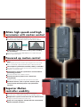
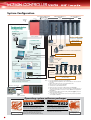
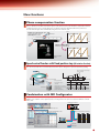
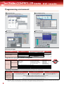
New Product News
SSCNETIII Compatible
MOTION CONTROLLER Q series
Taking motion control to the age of optics
Mitsubishi Electric Corporation Nagoya Works is a factory certified for ISO14001
(standards for environmental management systems) and ISO9001(standards for
quality assurance management systems)
EC97J1113
to Optics!
Taking the Various Possibilities
of the Servo System
Taking motion control to new ranges with
the high-speed synchronous network SSCNETIII!
MOTION CONTROLLER Qseries
compatible
Introducing the SSCNETIII compatible Q173HCPU/Q172HCPU to the Motion controller Q Series!
High speeds and high accuracies are attained to comply with the MELSERVO-J3 servo amplifier having
the industry’s highest performance(as of March 2005).
The conventional Q Series Motion controller’s functions and programming environment are incorporated.
(Note) • Q173HCPU/Q172HCPU can be connected only to the SSCNETIII compatible MR-J3-B.
• SSCNET(Servo System Controller NETwork)
- - - -
Attain 50Mbps high-speed communication
with optical communication
Improved system responsiveness!
Network communication speed
The speed of exchanging data between the controller
and servo amplifier has been greatly increased
thereby shortening the cycle time.
Speed increased
by approx. 10-fold
5.6
A173UHCPU/
Q173CPUN
50
Q173HCPU
Enhanced communication reliability!
0
10
20
30
40
50
Baud rate [Mbps]
The optical fiber cable was adopted.
Overall cable length
Improved freedom to device layout!
This model is compatible with long-distance wiring
(Maximum overall distance: up to 50[m] (164.04[ft.] )
between stations (Note) × number of axes).
Compatible with an approx.
25-fold long distance
30
A173UHCPU/
Q173CPUN
800
(Note)
Q173HCPU
(Note): When using long distance cable: 50[m] (164.04[ft.] ) between stations × 16
axes = 800[m] (2624.67[ft.] )
0
200
(656.17)
400
(1312.34)
600
800
(1968.50) (2624.67)
Distance [m(ft.) ]
Wiring is reduced by issuing the stroke limit signal and
proximity dog signal via the servo amplifier.
Machine wiring for SSCNETIII
Controller panel
Up to 50[m] (164.04[ft.] )
between stations*
MODE
RUN
ERR
USER
BAT
BOOT
POWER
MODE
RUN
ERR
USER
BAT
BOOT
SSCNETIII cable
PULL
PULL
PULL
USB
USB
RS-232
MR-J3-B
Amplifier panel
Machine
Amplifier panel
Machine
Amplifier panel
Enlarged view
Machine
FLS
DOG
RLS
(Note): When using long distance cable
Servo external signal (FLS, RLS, DOG)
2
The wire length can
be shortened
Attain high speeds and high
accuracies with motion control
Realized a 0.44ms operation cycle!
The operation cycle has been reduced by approx. half compared to the
conventional model, enabling high accuracy control with smooth commands.
Command position
Command position
When operation
cycle is shortened
Operation cycle
Operation cycle
Reduced the entire cycle time of the system, including
the servomotor!
This model is compatible with the MELSERVO-J3 servo amplifier having the
industry’s highest performance.
Powered up motion control
Improved synchronization accuracy between multiple
axes!
Errors caused by synchronous encoder’s processing time or the servo’s droop
pulses is automatically compensated with the phase compensation function.
262,144 pulse synchronous encoder (18-bit) is available!
The synchronous operation accuracy at low speeds is greatly improved (16-fold
compared to conventional model).
Simultaneous control of synchronous control and PTP
positioning possible!
Real mode and virtual mode combination function.
Security function to protect user’s know-how
incorporated!
A function to protect user programs with a password has been added.
Suitable for devices, such as spinners, with the speed
control function with fixed position stop (Orientation
function)!
Superior Motion
controller usability
Realized an integral engineering environment!
This system can be combined with the MT Developer and MR Configurator.
Multiple CPU system carried over with the Q Series PLC!
(Configure a system that matches the system scale.)
Easily use user programs created with the conventional
Motion controller Q Series!
3
III
System Configuration
Motion CPU control (Note-2)
modules
PLC CPU (Note-1) /Motion CPU
(Up to 4 modules)
Q
Q61P-A
(H)CPU Q17
HCPU(-T)
Q172LX
Q172EX-S2
Q173PX
PLC CPU control (Note-3)
modules
QI60
QX/Y
CPU base
Q3 B
Peripheral device
configuration
For PLC CPU
GX Developer Ver.6 or later
(CD-ROM)
SW D5C-GPPW-E
USB (Note-5)/RS-232
Device configuration
For Motion CPU
Operating system software (FD)
SW6RN-SV
Q
Motion CPU I/O
(Up to 256 points)
Battery holder unit
Q170HBATC (Note-7)
(Q6BAT has been installed)
External interrupt input (16 points)
Manual pulse generator (3 modules/unit)
MR-HDP01
Serial absolute synchronous encoder (2 modules/unit)
Q170ENC
SSC I/F card
A30CD-PCF
SSCNET (Note-4)
Servo external signal
(FLS,RLS,STOP,DOG/CHANGE) × 8 axes
USB (Note-5)
Laptop PC
(WinNT/Win98/Win2000/WinXP)
Integrated startup support environment
MT Developer
Ver.00K or later
(CD-ROM)
SW6RNC-GSVPROE
MR Configurator
(CD-ROM)
MRZJW3-SETUP221E
Teaching unit (Note-8)
A31TU-D K13
SSCNETIII (System1)
SSCNETIII
(System2)
Servo amplifier
MR-J3-B
SSCNET (Note-4)
Servomotor
Q173HCPU : 2 systems (Up to 32 axes) Q172HCPU : 1 system (Up to 8 axes)
SSC I/F board
A 0BD-PCF
Desktop PC (WinNT/Win98/Win2000/WinXP)
Integrated startup support environment
Extension cable QC
Graphic operation
terminal (GOT)
B
Extension base
Q6 B (Note-6)
(Up to 7 extensions)
Servo external signal (Note-9)
(FLS, RLS, DOG)
USB (Note-5)
Motion CPU/PLC CPU
control modules
Notes : 1. PLC CPU for Multiple CPU can be used in Q-mode.
2. Only input module among Motion CPU control modules can be accessed from
PLC CPU.
3. Other CPU modules cannot be accessed from Motion CPU.
4. Only 1 PC can be connected via SSCNET.
5. USB cannot be used in WindowsNT® 4.0.
6. Motion CPU cannot control the module installed to the QA1S6 B.
7. The external battery for backup of parameter/program is required at the time of
continuous power failure for 1000 hours or more. (Q6BAT is not supplied with
Q170HBATC).
8. In planning stages. When using the teaching unit A31TU-D K13, please use
Motion CPU for teaching unit.
9. Connecting target can be selected for each axis from general-purpose input of
servo amplifier or Q172LX.
Operating system software packages
Motion SFC compatible
SV13
Dedicated language
4
Conveyor assembly use
Motion SFC compatible
Automatic machinery use
SV22
[Applications] Electronic component assembly,
Inserter, Feeder, Molder, Conveying equipment,
Paint applicator, Chip mounting, Wafer slicer,
Loader/Unloader, Bonding machine, X-Y table
[Applications] Press feeder, Food processing,
Food packaging, Winding machine, Spinning
machine, Textile machine, Printing machine, Book
binder, Tire molder, Paper-making machine
Linear interpolation (1 to 4 axes), Circular
interpolation, Constant-speed, Fixed-pitch feed,
Speed control with fixed position stop, Speed
switching, Speed control, Speed/position switching
Synchronous control, Electronic shaft, Electronic
clutch, Electronic cam, Draw control
Mechanical support
language
New functions
Phase compensation function
When carrying out tracking synchronization with the synchronous encoder, delays in the processes, etc., cause the
phase to deviate at servomotor shaft end in respect to the synchronous encoder. The phase compensation function
compensates in this case so that the phase does not deviate. The phase deviation between the synchronous
encoder and cam angle can be eliminated by using this for the electronic cam.
Angle
Example of use with electronic cam
Operate a cutter with the electronic
cam in synchronization with the
conveyor speed
Synchronous encoder angle
Servomotor
Cam angle
Time
Phase deviates between synchronous encoder
and electronic cam.
P1
Phase compensation
Angle
Synchronous encoder angle
Synchronous encoder
1-axis
Cam angle
Electronic cam
(Servomotor)
Mechanical system
program
Time
Phase deviation is eliminated, and phases are
completely synchronized.
Speed control function with fixed position stop (Orientation function)
The servomotor can be rotated at preset speed and then stopped at preset position after the stop command ON.
Not only the speed but also acceleration/deceleration time can be changed to an optional value while operating.
Value changed with speed change
request command
v
b
a
Rotates at a fixed speed
c
t
d
Fixed position stop acceleration/deceleration time
ON
Servo program start
OFF
Speed change request
command
OFF
Fixed position stop command
OFF
ON
Stop at preset position
ON
Servomotor
Fixed position stop acceleration
/deceleration time
(Indirect setting device)
a
b
c
d
Combination with MR Configurator
Communication between the MR Configurator (setup software) and servo amplifier via Motion controller is possible.
Multiple servo amplifiers can be adjusted just by connecting between the personal computer and Motion controller
with a cable.
Q173HCPU/Q172HCPU
MODE
RUN
ERR
USER
BAT
BOOT
POWER
Click on
the icon!
PULL
PULL
Start MR Configurator by clicking the MR Developer icon
MODE
RUN
ERR
USER
BAT
BOOT
PULL
USB
USB
RS-232
Select the required number of axes
and display as a list.
Cables do not need to be reconnected
MR-J3-B
MR Configurator
Data write
Data read
5
III
Programming environment
Motion SFC monitor
Servo parameter setting
Color indication of executing step on flow chart
Device monitor and test of execution/specification step
Direct start of MT Developer in the parameter setting screen
Monitor/Test
Digital oscilloscope
Current value monitor/Axis monitor/Error history monitor
Various tests such as home position return/JOG operation by clicking mouse
Data sampling synchronized with motion control cycle
Waveform display/Dump display/Fail saving/Printing
Software packages
Software
Model name
Q173HCPU(-T)
Q172HCPU(-T)
Application
Conveyor assembly use SV13
Automatic machinery use SV22
Conveyor assembly use SV13
Operating system software
Programming software
Automatic machinery use SV22
Digital oscilloscope use
SW6RN-SV13QK
SW6RN-SV13QM
SW6RN-SV22QJ
SW6RN-SV22QL
SW6RN-GSV13P
SW6RN-GSV22P
SW3RN-CAMP
SW6RN-DOSCP
Note
–
Included in the
"Integrated start-up
support software".
Integrated start-up support software configration
Model name
Details
• Conveyor assembly software
• Automatic machinery software
• Cam data creation software
• Digital oscilloscope software
• Communication system software
• Document print software
SW6RNC-GSVE
(Ver.00K or later)
[1 CD-ROM]
SW6RN-GSVPROE
MT Developer
SW6RNC-GSVHELPE (Operation manual [1 CD-ROM] )
Installation manual
SW6RNC-GSVPROE
A30CD-PCF (SSC I/F card (PCMCIA TYPE II 1CH/card) )
Q170CDCBL3M (A30CD-PCF cable 3m(9.84ft.) )
SW6RNC-GSVSETE
Operating environment
IBM PC/AT with which WindowsNT4.0/98/2000/XP English version operated normally.
®
Item
CPU
Memory capacity
Hard disk free space
WindowsNT 4.0 (Service Pack 2 or later)
®
or Windows 98
Recommended Pentium® 133MHz or more
Recommended 32MB or more
®
®
Windows 2000
Recommended Pentium®
233MHz or more
Recommended 64MB or more
Windows XP
Recommended Pentium®
450MHz or more
Recommended 192MB or more
SW6RNC-GSVE: 250MB + SW6RNC-GSVHELPE: 81MB (Possible to select installation)
SVGA (Resolution 800 ✕ 600 pixels, 256 colors) or more
Display
Application software
: SW6RN-GSV13P
: SW6RN-GSV22P
: SW3RN-CAMP
: SW6RN-DOSCP
: SW6RN-SNETP
: SW3RN-DOCPRNP
SW20RN-DOCPRNP
Word 97, Excel 97 or Word 2000, Excel 2000 (For document printing)
Visual C++ 4.0 or more, Visual Basic 4.03 (32 bit) or more (For communication API function)
®
(Note) • When using the A30CD-PCF, the PC card driver for WindowsNT provided by the personal computer manufacturer must be used.
®
®
• WindowsNT , Windows , Word, Excel, Visual C++ and Visual Basic are either registered trademarks or trademarks of Microsoft Corporation in the United States and/or other countries.
®
• Pentium is trademarks or registered trademarks of Intel Corporation or its subsidiaries in the United States and other countries.
6
Motion control specifications
Item
Motion SFC Performance Specifications
Q172HCPU(-T)
Q173HCPU(-T)
8 axes
Number of control axes 32 axes (Up to 16 axes/system)
Operation cycle
0.44~
Linear interpolation (Up to 4 axes), Circular interpolation (2 axes),
Interpolation functions
Helical interpolation (3 axes)
PTP (Point to Point) control, Speed control, Speed-position control,
Fixed-pitch feed, Constant speed control, Position follow-up control,
Control modes
Speed control with fixed position stop, Speed switching control,
High-speed oscillation control, Synchronous control (SV22)
Item
Motion SFC
program capacity
Q173HCPU(-T) / Q172HCPU(-T)
Code total (Motion SFC chart +
Operation control + Transition)
Text total (Operation control+ Transition)
Number of Motion SFC programs
Motion SFC chart size/program
Motion SFC
program
Up to 4094 steps
Number of selective branches/branch
255
Parallel branch nesting
Number of operation control programs
Programming language Motion SFC, Dedicated instruction, Mechanical support language (SV22)
14k steps
Number of positioning points
3200 points (Positioning data can be designated indirectly)
IBM PC/AT
Programming tool
USB/SSCNET
Peripheral I/F
Teaching operation function
Home position return
function
Number of transition programs
Operation control
program (F/FS) /
Transition
program(G)
Provided (Q17 HCPU-T, SV13 use)
Proximity dog (2 types), Count (3 types), Data set (2 types),
Dog cradle, Stopper (2 types), Limit switch combined
Provided
JOG operation function
Manual pulse generator
Possible to connect 3 modules
operation function
Synchronous encoder Possible to connect 12 modules Possible to connect 8 modules
operation function
(SV22 use)
(SV22 use)
M-code output/M-code completion wait function provided
M-code function
Number of output points 32 points
Limit switch output
Watch data: Motion control data/Word device
function
Made compatible by setting battery to servo amplifier. (Possible to
Absolute position
select the absolute data method or incremental method for each axis)
system
Number of SSCNETIII
2 systems
1 system
systems (Note-1)
Number of usable
Q172LX
: 1 module
Q172LX
: 4 modules
motion related
Q172EX-S2 : 4 modules
Q172EX-S2 : 6 modules
interface modules
Q173PX
: 3 modules(Note-2)
Q173PX
: 4 modules(Note-2)
(Note-1) : The servo amplifiers for SSCNET cannot be used.
(Note-2) : When using the incremental synchronous encoder (SV22 use), you can use above
number of modules.
When connecting the manual pulse generator, you can use only 1 module.
256 (No.0 to 255)
Up to 64k bytes (Included Motion SFC chart comments)
Number of Motion SFC steps/program
Number of parallel branches/branch
Automatic trapezoidal acceleration/deceleration,
Acceleration/
S-curve acceleration/deceleration
deceleration processing
Compensation function Backlash compensation, Electronic gear, Phase compensation (SV22)
Servo program capacity
543k bytes
484k bytes
255
Up to 4 levels
4096 (F/FS0 to F/FS4095) with F(Once execution type)
and FS(Scan execution type) combined.
4096 (G0 to G4095)
Code size/program
Number of blocks(line)/program
Up to approx. 64k bytes (32766 steps)
Up to 8192 blocks (in the case of 4 steps(min)/blocks)
( ) nesting/block
Descriptive
Expression
Operation control program
Transition program
Number of multi executed programs
Up to 32
Calculation expression/bit conditional expression
Calculation expression/bit conditional
expression/comparison conditional expression
Up to 256
Number of multi active steps
Normal task
Execute
specification
Executed
task
Event task Fixed cycle
(Execution
External
can be
interrupt
masked.)
PLC interrupt
NMI task
Number of I/O points (X/Y)
Up to 256 steps/all programs
Executed in motion main cycle
Executed in fixed cycle
(0.88ms, 1.77ms, 3.55ms, 7.11ms, 14.2ms)
Executed when input ON is set among interrupt module
QI60 (16 points).
Executed with interrupt (GINT) from PLC CPU.
Executed when input ON is set among interrupt module
QI60 (16 points).
8192 points
Number of real I/O points (PX/PY)
• Internal relays(M), Latch relays: Total 8192 points
• Link relays (B) 8192 points
Number of devices • Annunciators (F) 2048 points
• Special relays (M) 256 points
• Data registers (D) 8192 points
256 points
• Link registers(W) 8192 points
• Special registers (D) 256 points
• Motion registers (#) 8192 points
• Coasting timers (FT) 1 point (888µs)
Motion related module specifications
Part name
Model name
Description
Use with Q PLC
Up to 32 axes control, Operation cycle 0.4[ms]~
Up to 8 axes control, Operation cycle 0.4[ms]~
Up to 32 axes control, Operation cycle 0.4[ms]~, For teaching unit
Up to 8 axes control, Operation cycle 0.4[ms]~, For teaching unit
Program capacity 8k steps
Program capacity 14k steps
Program capacity 28k steps
Program capacity 28k steps
Program capacity 60k steps
Program capacity 124k steps
Program capacity 252k steps
Power supply + CPU + 3 I/O slots, For Q series modules
Power supply + CPU + 5 I/O slots, For Q series modules
Power supply + CPU + 8 I/O slots, For Q series modules
Power supply + CPU + 12 I/O slots, For Q series modules
Power supply + 3 I/O slots, For Q series modules
Power supply + 5 I/O slots, For Q series modules
Power supply + 8 I/O slots, For Q series modules
Power supply + 12 I/O slots, For Q series modules
Length 0.45m(1.48ft.), 0.6m(1.97ft.), 1.2m(3.94ft.), 3m(9.84ft.), 5m(16.40ft.), 10m(32.81ft.)
100 to 120VAC input/ 5VDC 6A output
200 to 240VAC input/ 5VDC 6A output
100 to 240VAC input/ 5VDC 3A/ 24VDC 0.6A output
24VDC input/ 5VDC 6A output
100 to 120VAC/200 to 240VAC input/ 5VDC 8.5A output
Servo external signal 8 axes (FLS, RLS, STOP, DOG/CHANGE×8)
Serial absolute synchronous encoder Q170ENC interface×2, Tracking input 2 points (A6BAT built-in)
Manual pulse generator MR-HDP01/Incremental synchronous encoder interface×3, Tracking input 3 points
Resolution: 262144PLS/rev, Permitted speed: 3600r/min
Serial absolute synchronous encoder
Q170ENC
Permitted axial loads [Radial load: Up to 19.6N, Thrust load: Up to 9.8N]
Serial absolute synchronous encoder cable (Note-3)
Q170ENC ↔ Q172EX-S2 2m, 5m, 10m, 20m, 30m, 50m
Q170ENCCBL M
Battery holder unit
Battery holder for Q6BAT (Attachment: battery cable)
Q170HBATC (Note-2)
For IC-RAM memory backup of Q17 HCPU(-T) module (SFC programs, Servo programs, Parameters)
Q6BAT
Battery
For backup of Q170ENC
A6BAT
Pulse resolution: 25PLS/rev(100PLS/rev after magnification by 4), Permitted speed: 200r/min(Normal rotation)
Manual pulse generator
MR-HDP01
Permitted axial loads [Radial load: Up to 19.6N, Thrust load: Up to 9.8N], Open collector output
Standard code for inside panel
MR-J3BUS M
• Q17 HCPU(-T) ↔ MR-J3- B 0.15m(0.49ft.), 0.3m(0.98ft.), 0.5m(1.64ft.), 1m(3.28ft.), 3m(9.84ft.)
SSCNETIII cable (Note-3)
• MR-J3- B ↔ MR-J3- B
MR-J3BUS M-A
Standard cable for outside panel 5m(16.40ft.), 10m(32.81ft.), 20m(65.62ft.)
Long distance cable 30m(98.43ft.), 40m(131.23ft.), 50m(164.04ft.)
MR-J3BUS M-B (Note-4)
PCI bus loading type, 2ch/board
A10BD-PCF
SSC I/F board
ISA bus loading type, 2ch/board
A30BD-PCF
SSC I/F card
PCMCIA TYPE II, 1ch/card
A30CD-PCF
Cable for SSC I/F board (Note-3)
Q17 HCPU(-T) ↔ SSC I/F board 3m(9.84ft.), 5m(16.40ft.), 10m(32.81ft.)
Q170BDCBL M
Cable for SSC I/F card (Note-3)
Q17 HCPU(-T) ↔ SSC I/F card 3m(9.84ft.), 5m(16.40ft.), 10m(32.81ft.)
Q170CDCBL M
For SV13, With 3-position deadman switch, Only Japanese
A31TU-D3K13
Teaching unit (Note-5)
For SV13, Without deadman switch, Only Japanese
A31TU-DNK13
Q17 HCPU-T ↔ A31TU-D3K13, 3m(9.84ft.)
Q170TUD3CBL3M
(Attachment : short-circuit connector (A31TUD3TM) for teaching unit)
Cable for the teaching unit
Q17 HCPU-T ↔ A31TU-DNK13, 3m(9.84ft.)
Q170TUDNCBL3M
Q170TUDNCBL03M-A Exchange cable for direct connection of Q17 HCPU-T ↔ A31TU-DNK13, 0.3m(0.98ft.)
For direct connection to Q17 HCPU-T, It is packed together with Q17 HCPU-T.
Q170TUTM
Short-circuit connector for teaching unit
For connection to Q170TUD CBL3M, It is packed together with Q170TUD CBL3M.
A31TUD3TM
(Note-1) : Please use the power supply module within the range of power supply capacity.
(Note-2) : Battery Q6BAT is not attached to Battery holder unit Q170HBATC. Please arrange separately.
(Note-3) : =Cable length (015: 0.15m(0.49ft.), 0: 0.3m(0.98ft.), 05: 0.5m(1.64ft.), 1: 1m(3.28ft.), 2: 2m(6.56ft.), 3: 3m(9.84ft.), 5: 5m(16.40ft.), 10: 10m(32.81ft.), 20: 20m(65.62ft.), 30: 30m(98.43ft.), 40: 40m(131.23ft.), 50: 50m(164.04ft.))
(Note-4) : Please contact your nearest Mitsubishi sales representative for the cable of less than 30m(98.43ft.).
(Note-5) : In planning stages.
Q173HCPU
Q172HCPU
Motion CPU module
Q173HCPU-T
Q172HCPU-T
Q00CPU
Q01CPU
Q02CPU
PLC CPU module
Q02HCPU
Q06HCPU
Q12HCPU
Q25HCPU
Q33B
Q35B
CPU base unit
Q38B
Q312B
Q63B
Q65B
Extension base unit
Q68B
Q612B
Extension cable
QC B
Q61P-A1
Q61P-A2
(Note-1)
Power supply module
Q62P
Q63P
Q64P
Servo external signals interface module
Q172LX
Serial absolute synchronous encoder interface module Q172EX-S2
Manual pulse generator interface module
Q173PX
7
MOTION CONTROLLERS Q series –SSCNETIII Compatible–
Exterior dimensions
Q173HCPU (-T)
Q172HCPU (-T)
Q173HCPU-T
Q172HCPU-T
MODE
RUN
ERR.
M.RUN
BAT.
BOOT
MODE
RUN
ERR.
M.RUN
BAT.
BOOT
FRONT
FRONT
SSCNETIII
CN2
TU
PULL
BAT
CN1
PC
TU
PULL
USB
27.4(1.08)
114.3(4.50)
USB
Q172LX
27.4(1.08)
114.3(4.50)
[Unit : mm(inch)]
Q172EX-S2
Q172LX
[Unit : mm(inch)]
Q173PX
Q173PX
Q172EX-S2
PLS.A PLS.B TREN
1
1
1
2
2
2
3
3
3
SY.ENC TREN
1
1
2
2
CTRL
98(3.86)
98(3.86)
SY.ENC1
PULSER
98(3.86)
PC
104.6(4.12)
BAT
104.6(4.12)
SSCNETIII
CN1
SY.ENC2
Q172LX
90(3.14)
Q173PX
Q172EX
27.4(1.08)
[Unit : mm(inch)]
90(3.14)
27.4(1.08)
[Unit : mm(inch)]
90(3.14)
27.4(1.08)
[Unit : mm(inch)]
For safe use
• To use the products given in this catalog properly, always read the “manuals” before
starting to use them.
• These products have been manufactured as a general-purpose part for general
industries, and have not been designed or manufactured to be incorporated in a
device or system used in purposes related to human life.
• Before using the products for special purposes such as nuclear power, electric
power, aerospace, medicine, passenger movement vehicles or under water relays,
contact Mitsubishi.
• These products have been manufactured under strict quality control. However, when
installing the product where major accidents or losses could occur if the product fails,
install appropriate backup or failsafe functions in the system.
• When exporting any of the products or related technologies described in this
catalogue, you must obtain an export license if it is subject to Japanese Export
Control Law.
Precautions for Choosing the Products
Mitsubishi will not be held liable for damage caused by factors found not to be the
cause of Mitsubishi; opportunity loss or lost profits caused by faults in the
Mitsubishi products; damage, secondary damage, accident compensation caused
by special factors unpredictable by Mitsubishi; damages to products other than
Mitsubishi products; and to other duties.
HEAD OFFICE : MITSUBISHI DENKI BLDG., 2-2-3, MARUNOUCHI, CHIYODA-KU, TOKYO 100-8310, JAPAN
SV0503-2 <MDOC>
New publication, effective March 2005
Specifications subject to change without notice.