1
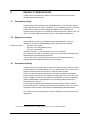
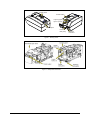
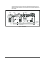
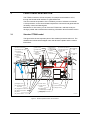
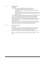
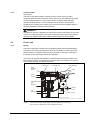
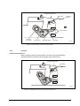
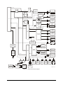
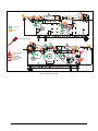
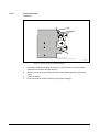
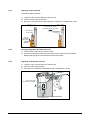
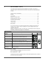
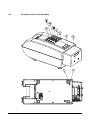
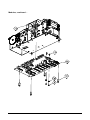
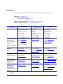
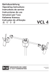
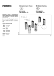
Zebra® TTPM3™ Kiosk Ticket Printer/Encoder Service Manual P1011350-001 © 2009 ZIH Corp. The copyrights in this manual and the software and/or firmware in the printer described therein are owned by ZIH Corp. Unauthorized reproduction of this manual or the software and/or firmware in the printer may result in imprisonment of up to one year and fines of up to $10,000 (17 U.S.C.506). Copyright violators may be subject to civil liability. This product may contain ZPL®, ZPL II®, and ZebraLink™ programs; Element Energy Equalizer® Circuit; E3®; and Monotype Imaging fonts. Software © ZIH Corp. All rights reserved worldwide. ZebraLink and all product names and numbers are trademarks, and Zebra, the Zebra logo, ZPL, ZPL II, Element Energy Equalizer Circuit, and E3 Circuit are registered trademarks of ZIH Corp. All rights reserved worldwide. All other brand names, product names, or trademarks belong to their respective holders. For additional trademark information, please see “Trademarks” on the product CD. Proprietary Statement This manual contains proprietary information of Zebra Technologies Corporation and its subsidiaries (“Zebra Technologies”). It is intended solely for the information and use of parties operating and maintaining the equipment described herein. Such proprietary information may not be used, reproduced, or disclosed to any other parties for any other purpose without the express, written permission of Zebra Technologies Corporation. Product Improvements Continuous improvement of products is a policy of Zebra Technologies Corporation. All specifications and designs are subject to change without notice. Liability Disclaimer Zebra Technologies Corporation takes steps to ensure that its published Engineering specifications and manuals are correct; however, errors do occur. Zebra Technologies Corporation reserves the right to correct any such errors and disclaims liability resulting therefrom. Limitation of Liability In no event shall Zebra Technologies Corporation or anyone else involved in the creation, production, or delivery of the accompanying product (including hardware and software) be liable for any damages whatsoever (including, without limitation, consequential damages including loss of business profits, business interruption, or loss of business information) arising out of the use of, the results of use of, or inability to use such product, even if Zebra Technologies Corporation has been advised of the possibility of such damages. Some jurisdictions do not allow the exclusion or limitation of incidental or consequential damages, so the above limitation or exclusion may not apply to you. P1011348-001 TTPM2™ Selection Guide 2/18/09 CONTENTS March, 09 1 INTRODUCTION .............................................................................................5 1.1 About this manual............................................................................................5 1.2 Updating ..........................................................................................................5 2 PRODUCT PRESENTATION .........................................................................6 2.1 Document printing ...........................................................................................6 2.2 Magnetic encoding ..........................................................................................6 2.3 Document handling..........................................................................................6 3 FUNCTIONAL DESCRIPTION .......................................................................9 3.1 Standard TTPM3 model ..................................................................................9 3.2 Front Load .................................................................................................... 11 3.3 Control board................................................................................................ 16 4 MAINTENANCE ........................................................................................... 20 4.1 Preventive maintenance............................................................................... 20 4.2 Fault finding .................................................................................................. 22 4.3 Service checklist TTPM3.............................................................................. 23 4.4 Parts removal and replacement ................................................................... 25 5 ADJUSTMENTS........................................................................................... 31 5.1 Preparation ................................................................................................... 31 5.2 Ticket path adjustment ................................................................................. 32 5.3 Magnetic head pressure rollers adjustment ................................................. 35 5.4 Solenoids...................................................................................................... 36 5.5 Printers with front load.................................................................................. 38 TTPM3 - Service Manual 3 6 REPLACEMENT PARTS............................................................................. 39 6.2 Desktop version, final assembly................................................................... 40 6.3 Modules ........................................................................................................ 44 6.4 Input module................................................................................................. 48 6.5 Magnetic encoding module .......................................................................... 50 6.6 Pressure Roll Assy. Track 1-3...................................................................... 50 6.7 Printhead module assembly ......................................................................... 51 6.8 Output module .............................................................................................. 52 6.9 Cutter module ............................................................................................... 54 6.10 Basic Module ................................................................................................ 58 64 4 TTPM3 - Service Manual March 2009 1 INTRODUCTION 1.1 About this manual This manual describes the design and function of the TTPM3 Ticket Printer/Encoder, which creates credit-card-wide documents with magnetic encoding and thermal printing. The manual also contains maintenance instructions and replacement parts lists. 1.2 Updating This manual will be updated as, from time to time, printer functions and features may be added or amended. You will always find the latest edition on our web site (www.zebra.com). If you require functions not found in the manual edition at your disposal, you are welcome to consult one of our offices for information. March, 09 TTPM3 - Service Manual 5 2 PRODUCT PRESENTATION TTPM3 Ticket Printer/Encoder creates credit-card-wide tickets with magnetic encoding and thermal printing. 2.1 Document printing TTPM3 uses the direct thermal printing technique and can print the entire surface of the ticket with text, bar codes, or graphics, or any combination hereof. Text block position and orientation is software programmable as is the character size. The data sent to the printer is converted to a ticket image which is stored in the unit until an ”All Clear” software command is sent, or the power is turned off/on. 2.2 Magnetic encoding Three magnetic tracks can be encoded: Either with standard low coercivity recording, or optional “household-magnet proof” high coercivity recording. 1 ISO track version : ISO track 1 at 210 BPI ISO track 2 at 75 BPI (Bits-Per-Inch) ISO track 3 at 210 BPI Center track version: 7 mm wide center track at 75 or 210 BPI The TTPM3 can be used for encoding on one, two, or three tracks simultaneously. Read-after-write is automatically performed. You can also enter an already encoded ticket into the TTPM3 and read the magnetic stripe and output the data to the host computer. 2.3 Document handling TTPM3 printer has two rear inputs for ticket stock. Both can take continuous ticket stock like fanfold or roll ticket material. You can configure the printer so that one is used for continuous stock and the other is used for handfed tickets. There is an optional front load mechanism that makes it possible to load single tickets through the ticket exit. This replaces the upper ticket entry at the rear of the printer. In addition to this, the front load has a wastebasket function for redirecting used or invalid tickets to a wastebasket, thus preventing useless tickets being presented to the customer. You can select to partially eject the ticket so that the customer takes it from the frontload mechanism, or fully eject the ticket so that it falls into a tray. You can also select that a ticket should be redirected to a wastebasket as described above. The TTPM3 comes as desktop printer, or as an OEM printer mechanism for kiosk applications. 1 6 Encoding in ISO standard format, or in hexadecimal format (bit-by-bit), is software selectable. TTPM3 - Service Manual March 2009 Control panel Power switch Input 2 (upper) Input 1 (lower) Ticket output Power inlet (24V) Interface connector Figure 1. Desktop printer Figure 2. OEM printer mechanism March, 09 TTPM3 - Service Manual 7 The figure below shows the main parts of the OEM-type printer/encoder unit with attached front load mechanism. Items in the figure, but not pointed to belong to the basic module. Front load module (optional) Printhead module Output module Magnetic stripe module Input module Control board assy Protective plate Basic module Cutter module SW95039A Figure 3. TTPM3 modules 8 TTPM3 - Service Manual March 2009 3 FUNCTIONAL DESCRIPTION The TTPM3 connects to a host computer, for example a workstation or a PC, through the RS232 serial interface or optional Ethernet. The host controls the operation of the TTPM3 by means of software commands. A microprocessor on the control board interprets the commands and generates the necessary control and data signals. Besides the on-line mode, you can force the TTPM3 into a self-test mode producing a printed and encoded ticket containing information about firmware version. 3.1 Standard TTPM3 model The figure below shows important parts of the standard printer/encoder unit. The shaded lines indicate which stepper motor that drives the platen and the various feed rollers. (a) Feed control roller (b) Feed belts (O-rings) (c) Printhead support plate (g) Read head (h) Cutter pos. sensor (i) After cutter sensor (j) Feed control roller (k) Upper input sensor (l) Top-ofform sensor (m) Lower input sensor (n) Feed roller lower (o) Feed roller upper FRONT (d) Thermal print head (e) Print platen (f) Write head (z) Stepper motor (u) Cutter motor (r) Rocker (v) Cutter-home sensor (s) Feed control slide (ab) Engagement solenoid (x) Engagement solenoid upper entry (t) Stepper motor (ad) Knife (ae) Carrier wheel (q) Retaining plate BACK (aa) Printhead engagement arm (ac) Feed control slide (p) Retaining roller (y) Engagement solenoid lower entry SW95040B Figure 4. Standard printer/encoder unit mechanics March, 09 TTPM3 - Service Manual 9 3.1.1 Document paths See Figure 4. The TTPM3 can handle the following document path combinations: Two software-selectable paths for fanfold or roll stock. One path for a fanfold or roll stock and one single-document path with override function. Lower document path used for automatic insertion of single cards from an optional card dispenser fitted at the back of the TTPM3. Upper document path is not used. The figure shows the TTPM3 design with two software- selectable paths for fanfold or roll stock. The shaded lines indicate feed rollers directly driven by stepper motors via gear wheels. The un-shaded rollers are guide or pressure rollers. Roller (p) presses the document against retaining plate (q). When the document is retracted to a standby position, the roller prevents the document from slipping out of the input module. Each document path has an opto-sensor detecting the insertion and the presence of a document. Other opto-sensors alert the system about the position and the presence of the document on its way through the printer/encoder unit. 3.1.2 Document feed control See Figure 4. The input and output modules have one feed control roller each, (a) and (j). The rollers can be moved vertically by means of engagement solenoids and feed control slides that press the ticket against the feed roller or feed belts. The rear, lower solenoid (y) moves the slide through an intermediate rocker plate (r). The rear, upper solenoid (x) is only fitted if the TTPM3 has two fanfold or roll stock paths. 10 TTPM3 - Service Manual March 2009 3.1.3 Cutting module See Figure 4. The knife in the cutting module moves by means of a DC-motor (u) with a combined carrier and cam wheel (ae). The motor runs in one direction only during normal cutting operations. A micro-switch sensor (v) detects when the knife reaches its home position. If the mechanism cannot reach its home position, possibly due to a paper jam or similar, the motor will run in the opposite direction until the mechanism reaches its home position. WARNING! DANGER OF INJURY. Depending on the position of the carrier wheel on the cutter module, the cutting mechanism may start moving when the mains power supply is switched ON. KEEP HANDS AWAY WHEN SWITCHING ON THE POWER. 3.2 Front Load 3.2.1 Design The Front Load option consists of an input/output module and a printhead lifting mechanism. The front load option also has a lift mechanism for raising the in/out feeder assembly to enable a document to be directed out through an opening at the bottom of the input/output module to a waste bin. The printer can be programmed either to hold the ticket so that the customer can take it from the printer, or fully ejects the ticket so that it can fall down into a tray or bowl and the customer can take it from there. Pressure roll FL3 feeder assy Print head assy Paper presence sensor Platen Chute Feed roll Intermediate gear Solenoid Stepper motor Link Plunger Screw SW97095FL3 Figure 5. Front load input/output module design. Note that the feed roller is in the very front of the unit so that the ticket can be dropped into a bowl. March, 09 TTPM3 - Service Manual 11 Printhead module assy Front load module Print platen Micro switches Eccentric cam wheel Actuator arm Adjustment plate Lock screw SW97093B Figure 6. Printhead lifting mechanism design (optional) 3.2.2 Function FEEDING THE DOCUMENT IN When the paper presence sensor detects a document, the printhead lifting mechanism lifts the printhead and the stepper motor starts turning. Printhead module assy Print platen SW97093A Figure 7. Printhead lifted to accept document inserted at the front 12 TTPM3 - Service Manual March 2009 The document is fed through the front load input/output module into the ordinary “output module” now also serving as an input device. A leaf spring ensures that the document is kept pressed against the running feed belts to get sufficient friction. Paper presence detector Feed roll Print head Leaf spring Document Stepper motor SW97096-R2 Figure 8. Document is fed through into the ordinary output module The document moves all the way into the upper rear document path. The application program decides whether the document should be decoded, encoded, printed, or disposed of. March, 09 TTPM3 - Service Manual 13 FEEDING THE DOCUMENT OUT Returning the document through the input/output module (can also be fed out through the rear document path) is the reverse of feeding the document in. Note that the document is guided out through the horizontal path (see arrow). Document SW97098 Figure 9. Feeding the document out the normal way 14 TTPM3 - Service Manual March 2009 Alternatively, the document can be fed out downward into a waste bin or similar. This is affected by a software command that actuates the solenoid that pushes the link upward and pivots the input module so that the document is guided downward and out. In/out feeder Document Link Deflection plate Solenoid SW97099-R1 Figure 10. Dropping the document into a waste bin or similar March, 09 TTPM3 - Service Manual 15 3.3 Control board See Figure 12. TTPM3 functional block diagram on page 19 and the logic diagram in Chapter 5. 3.3.1 Microprocessor system The main parts of the microprocessor system are 80C420 processor 2MB FlashPROM 128 K RAM Two programmable I/O ports 3.3.2 Memory The Flash stores system parameters, fonts and firmware. The RAM stores print data saved in a page memory area that can be further split into one area for fixed, recurring, information and one area for variable information. The content of the RAM is deleted when power is turned off while the data in the Flash remains. 3.3.3 Printing The printhead has 384 heating elements in a single line. This corresponds to 48 bytes of print data per dot line. The printhead has its own CPU-like logic circuitry with a separate 4 MHz oscillator. Data to be printed is transferred on the data bus to the printhead, where the data is shifted byte-wise into a 48-byte wide register before a dot line is printed. The thermal coating on the document changes from white to black color at a specific temperature. The warmer the printhead, the less heating energy is needed and vice versa. Therefore, the printhead contains a thermistor connected to a voltage controlled oscillator (U11) on the control board. The frequency of the output signal TEMP is proportional to the printhead temperature. The microprocessor uses the TEMP signal to set the duty cycle of the regulated voltage applied to the heating elements. 3.3.4 Magnetic stripe encoding and reading The magnetic stripe module encodes and reads ISO tracks 1, 2 and 3 with low or high coercivity. A center track magnetic module is also available, but the electronics is the same with the recording and reading heads connected to track 2. The module is connected to the control board through connector J3. Data write and enable signals are transferred to the magnetic stripe module through the I/O port (U5). Read clock signals (MCRCLK1, MCRCLK2) and data signals (MCRDATA1, MCRDATA2) are transferred directly to the microprocessor (U2), the clock signals as interrupts. The setting of parameter 3 affects the magnetic stripe function as follows: n3 1= Disable read-after-write. 0= Enable read-after-write. 16 TTPM3 - Service Manual March 2009 3.3.5 Cutting The DC-motor first turns in one direction to perform the cutting. The cam wheel actuates the micro-switch sensor when the mechanism reaches its home position again. At this moment, the motor is forced to a quick stop as the drive circuit for turning the motor in the opposite direction is activated momentarily. 3.3.6 Communications interface The TTPM3 communicates with the host through the RS232 serial interface. The transfer rate is 115200 baud as default but can be set to other speeds with parameter 1. Circuit U13 adapts the TTL-levels to RS232 levels. The communication protocol is: 8 data bits 1 stop bit No parity RTS/CTS handshaking The setting of parameters 2 and 6 affects the communication as follows: n2 1= RTS/CTS 2= XON/XOFF n6 March, 09 1= 0= ACK/NAK (+ error code) enabled Disabled (silent) TTPM3 - Service Manual 17 3.3.7 Power supply The power supply unit (PSU) is of the switched mode type and supplies +24V to the control board. A transistor on the control board switches ON the +24 V when motors, solenoids and printhead is to be used and keeps it off when the printer is idle. This is to prevent the drive circuits in the printhead from becoming damaged since their status is undefined before the +5 V is at correct level. NOTE! — At these high currents it is essential that the leads and connectors be in good condition. Excessive resistance in these parts may cause very strange behavior of the printer. With Zebra power supplies, just connect the cable from the power supply to J5. If you use another type of power supply unit, 24 V cables are available from Zebra, order No. 01370-000. Should you make cables of your own, connect the voltages according to the following illustration. Note that protective ground and minus output should not be interconnected in the power supply. At the printer end of the cable, use an AMP Mate-N-Lok connector housing and two contact-sockets: Housing: AMP No. 350777-1 Socket: AMP No. 350689-1 GND +24 V Figure 11. Power connection Mode Idle 150 mA Standard text printing 2A average Peak current 6A Table 1. Current consumption NOTE! – 18 The 24 V ground, as well as the chassis of the printer, must be connected to ground potential (safety ground). TTPM3 - Service Manual March 2009 A8—A15 RAM ADDR. LATCH D0—D7 A0—A15 A0—A7 U4 U3 J1 PRINTHEAD DRIVER U8, U9, U12 PRINTHEAD THERMISTOR VOLTAGE CONTROLLED OSCILLATOR Flash PROM U10 J24 U11 PRINTER STEPPER MOTOR D0—D7 CPU J23 Q1—Q4 U19, U20 CHIP SELECT U1 ENCODING STEPPER MOTOR J21 CUTTER MOTOR DRIVE CIRCUIT A0, A1 CUTTER MOTOR HOME SENSOR Q6, Q7, Q19, Q20 D0—D7 J17 UPPER ENTRY SOLENOID U2 I/O PORTS J18 LOWER ENTRY SOLENOID SOLENOID DRIVERS J19 OUTPUT SOLENOID J20 U6 Q15—Q18 J22 PRINTHEAD LIFT MOTOR DRIVE CIRCUIT TTL TO RS232 VOLTAGE ADAPTATION U13 FRONT LOAD DUMP MECH. SOLENOID PRINTHEAD LIFT MECH. & POSITION SENSORS 2nd REAR BUTTON RED LED A0, A1 Pole 2: RDX Pole 3: TXD Pole 4: DTR Pole 5: GND Pole 7: RTS Pole 8: CTS I/O PORTS LAMP DRIVE CIRCUITS AMBER LED 2nd FRONT BUTTON GREEN LED FRONT BUTTON D0—D7 Q10—Q14 J15 J16 LOWER TRACK STANDBY POS. SENSOR J2 HOST +24V Tranistor switch +5V U5 Regulator J3 REAR BUTTON EXTERNAL POWER SUPPLY UNIT ON/OFF SWITCH LOGIC BLUE LED J7 J6 UPPER ENTRY INPUT SENSOR LOWER ENTRY INPUT SENSOR J8 TOP-OFFORM SENSOR J9 CUTTING POSITION SENSOR J10 AFTER CUTTING SENSOR J11 FRONT LOAD PAPER SENSOR MAGNETIC STRIPE MODULE SW95041-TTPM3 J5 Figure 12. TTPM3 functional block diagram March, 09 TTPM3 - Service Manual 19 4 MAINTENANCE WARNING! DANGER OF INJURY! Depending on the position of the crank mechanism in the cutter module, the cutting knife may start moving when the printer is switched ON. KEEP HANDS AWAY! CAUTION! The power supply should be switched off before you disconnect or connect any other cable on the control board. The printer electronics might otherwise be damaged. CAUTION! The printhead and some components on the control board are sensitive to ESD (electrostatic discharges). To prevent damaging such components, observe all the usual precautions such as keeping the part in its original packing (“ESD-bag”) until you are ready to install the part. Do not touch its pins. Use a grounded wrist strap when handling ESD-sensitive components. 4.1 Preventive maintenance Clean the paper path and document sensors from dust and paper particles at regular intervals. The operator usually does this. Clean rubber feed rollers, and feed belts, pressure rollers, printhead, and read/write heads with isopropyl alcohol when necessary. Clean the sensors with compressed air (available on spray cans). CAUTION! NEVER use petroleum based cleaning agents. The rubber platens and rollers will be destroyed. Oil the bearings and the cutting mechanism sparingly with Dexron II oil or similar when necessary. Apply grease on hubs, camwheels etc. according to the illustration on the next page. 20 TTPM3 - Service Manual March 2009 = Grease = Oil = Red laquer sealant = Apply on thread: Loctite 243 Threadlocker, medium strength, removable, and oil tolerant Figure 13. Lubricating a TTPM3 March, 09 TTPM3 - Service Manual 21 4.2 Fault finding The TTPM3 informs the host of some error symptoms by means of status reports and error codes (if not disabled with parameter n6). The indicators on the control panel indicate errors requiring assistance of the operator. Both parameter settings and error codes are described in the TTPM3 Technical Manual Below follow some hints on other error symptoms and how to act upon them: SYMPTOM Varying space between lateral dot lines as a result of irregular paper feed. ACTION Check that the output module is fully seated in the basic module and that the gear wheel of the output module is in mesh with the gear wheel of the basic module. SYMPTOM No cutting, bad cutting, uneven cut edges, etc. ACTION Remove any obstructing paper particles in the cutting mechanism. Check that the cutting motor and home position sensor connectors are fully seated on the control board. SYMPTOM Magnetic stripe encoding and decoding errors. ACTION Clean R/W heads, feed rollers, and O-rings with isopropyl alcohol. Check that the input module is fully seated in the basic module and that the gear wheel of the output module is in mesh with the gear wheel of the basic module. Check that the feed rollers are properly adjusted. Check the connections to the control board. SYMPTOM Ticket backs out of the input module when it should not. ACTION Check sensor levels Clean sensors Verify that preprint does not disturb sensor by loading a white ticket and measure levels. 22 TTPM3 - Service Manual March 2009 SYMPTOM Only one self-test ticket can be done. When you press the print button again, only blank tickets are produced. ACTION Check the setting of parameter n7, "Clear memory after print". If it is ON, this is the correct behavior. If n7 is OFF, test the printer with another power supply unit. If the power supply fails to deliver enough current, the printer is reset when the black line at the end of the self-test ticket is printed. 4.3 Service checklist TTPM3 The following steps should be carried out in a normal TTPM3 service. This list can be copied and each step ticked off ; in the boxes as a protocol. March, 09 TTPM3 - Service Manual 23 Cover Remove the four screws holding the printer mechanism to the bottom of the cover. Lift the printer-mechanism out of the cover. Print Module Open the printhead and clean the printhead resistor-line with alcohol. Check the plastic cogwheels for wear. Check for wear in bearings. Check that the plastic cogwheel fastening bolts do not jiggle (are secured with Loctite) Output Module Remove the output module. Check for damages on the feed roller and pressure rollers. Replace at signs of wear. Clean platens and rollers. Check the o-rings for cracks and wear. Replace if necessary. Clean the sensors with alcohol. Clean frame module from cutter dust. Check that the cogwheel shafts are fastened to the frame. Check that the ticket width setting is correct using gauge 02443-000. Input module Remove the input module Check for damages on the platen. (The urethane plastic may wear where the magnetic strip passes.) Replace at signs of wear. Clean platens and rollers. Check that all circlips are in place. Clean the sensors with alcohol. Check that the ticket width setting is correct using gauge 02443-000. Magnetic module Clean the magnetic heads with alcohol. Check that the heads do not have excessive wear. Replace magnetic module if worn. 24 Cutter Check blades for wear. Lubricate the fastening of the moving blade with grease. Refitting the modules Fit the input and output modules. Fit the printhead pressure plate. Use new circlips. Adjust the Maghead rollers to the thickness of the customers' tickets, make sure grove is upwards!. Check that all screws are firmly tightened. Lubricate all bearings with gearbox oil. Connect the indicator/push-button cable to the control board. Fit the mechanism in the cover. Connect the power supply. Testing Check using self-test printouts: Check that the solenoids of the input module pull the tickets in correctly. Adjust if necessary. Check with tickets in the upper entry. Print on the same ticket several times to see that the text is positioned about the same each time you print. Check with the printer on-line: Use a terminal program or the TTP editor. Print a 380x10-pixel bitmap. Check that all pixels are black. Replace the printhead if necessary. Set parameter n3 to 2 for “dual entry”. Check that the solenoids for entry changing works correctly and that the non selected ticket entry backs out enough so that the tickets do not collide. Print 50 tickets with encoding to check if the coding works correctly and that the handshaking of the serial communication works. Reset the parameters to the customer's configuration. Clean the cover. TTPM3 - Service Manual March 2009 4.4 Parts removal and replacement Whenever modules are loosened, removed or replaced, a complete adjustment and verification cycle must be performed. NOTE 1! — This is essential for the reliability of the printer and should NEVER be overlooked! NOTE 2! — Only technicians having the appropriate knowledge and experience of the TTPM3 should carry out the adjustments. WARNING! DANGER OF INJURY. Depending on the position of the carrier wheel on the cutter module, the cutting mechanism may start moving when the mains power supply is restored. KEEP HANDS AWAY! DISCONNECT THE POWER CABLE BEFORE DISASSEMBLING THE UNIT! See figure 20 for connector numbering and interconnections. 4.4.1 Tools required Tool Part No. Screwdriver Phillips No. 0 Screwdriver Phillips No. 1 Screwdriver Slot 3x75 Screwdriver Torx T9 Hexagonal wrench 1.5 mm Hexagonal wrench 3 mm Nut driver 4 mm Nut driver 5.5 mm Nut driver 7 mm Block wrench 8 mm Tension-spring hook Circlip tool for RS 2.3 clips Circlip tool for RS 3.2 clips Circlip tool for RS 4 clips ISO ticket width gauge Set of feeler gauges Vacuum cleaner with computer type hose and brush set Compressed air Isopropyl alcohol Gear oil, for example ATF oil type Dexron II, or Shell Tegula 27 oil Grease type “HASCO Z260” Vaseline spray “type “Bajol” 4.4.2 02542-000 02542-001 02543-030 02449-009 02445-015 02445-030 02541-040 02541-055 02541-070 01802-080 102820 102177 102818 102819 02443-000 - Torque settings, and thread locking Do not over-tighten the screws. The max torque for the different screw sizes are as follows: M2 = 0,13 Nm, M2.5 = 0,26 Nm, M3 = 0,46 Nm, and M4 = 1.1 Nm. Threadlock like Locktite 243 should be used on screws that hold plastic parts, for instance the screws for the micro-switches. March 2009 TTPM3 - Service Manual 25 4.4.3 Firmware The firmware is the software that controls the TTPM3. It is stored in a Flash PROM and can be updated from the host computer. How to do this is described in the Technical Manual. You can download firmware from www.zebra.com. 4.4.4 Cover REMOVAL 1. Turn the printer upside down. 2. Remove the four screws securing the printer/encoder unit to the bottom pat of the cover. 3. Lift the printer/encoder mechanism out of the Cover. REPLACEMENT Install the module in the reverse order. 26 TTPM3 - Service Manual March 2009 4.4.5 Printhead module REMOVAL 1. Disconnect the printhead cable from the printhead. 2. Remove the two circlips from the shaft attaching the printhead support plate to the output module. 3. Pull the printhead engagement arm forwards to relieve the printhead and then pull out the shaft completely. REPLACEMENT If the output module has been removed as well, this one should be mounted on the basic module before you fit the printhead module. 1. Mount the printhead module in the reverse order. 2. Check that the printhead engagement arm connects to the spring-loaded rod extending outside the left side of the basic module. 3. If the output module had been removed as well, check that is fully seated on the basic module so that the gear wheels are correctly in mesh. 4.4.6 Output module REMOVAL 1. Remove the printhead module as described above. 2. Disconnect the sensor cable from the control board connector J10. Write the connector No. on the connector housing using a permanent marker pen so you easily can reconnect it to the right header. 3. Loosen the two Allen-screws securing the output module to the basic module. 4. Bend the feed control slide out a little and remove the output module. REPLACEMENT The printhead module should not be mounted on the output module yet. 1. Bend the feed control slide out a little and lower the output module on to the basic module. 2. Tighten the two Allen-screws and check that the gear wheels engage correctly. 3. Connect the sensor cable to the control board connector J10. 4. Mount the printhead module as described above. 4.4.7 Input module REMOVAL 1. Mark and disconnect the sensor cables from the control board connectors J6—J9 + J15. 2. Loosen the four screws securing the input module to the basic module. 3. Bend the feed control slide out a little and remove the input module. REPLACEMENT 1. Bend the feed control slide out a little and lower the input module on to the basic module. 2. Check that the gear wheels engage correctly before you tighten the four screws firmly. 3. Connect the cables to the control board connectors J6—J9 + J15. March 2009 TTPM3 - Service Manual 27 4.4.8 Magnetic stripe module REMOVAL 1. Remove the printer/encoder unit from the cabinet as described above. 2. Remove the input module as described above. 3. Disconnect the two cables from the control board connector J3. 4. Remove the four screws securing the magnetic stripe module. 5. Remove the magnetic stripe module. Save the two plastic spacers located under the magnetic stripe module. REPLACEMENT Mount the module in the reverse order. Push the module towards the cutter to get it straight, and then tighten the screws. 4.4.9 Cutter module REMOVAL 1. Remove the printer/encoder unit from the cabinet. 2. Remove the input module and the magnetic stripe module as described above. 3. Remove the printhead module. 4. Remove the output module. 5. Remove the four screws holding the cutter module in position. The screws (two screws on each side) are located below the big holes in the side plates of the basic module. 6. Disconnect the cable from the control board connector then mark the housing with “J21” so it is easy to reconnect. 7. The shaft of the cutter motor extends so far that you have to press the side plates of the basic module slightly apart while you remove the cutter module. REPLACEMENT Fit the cutter module in the reverse order. WARNING! DANGER OF INJURY. Depending on the position of the carrier wheel on the cutter module, the cutting mechanism may start moving when the mains power supply is switched ON. KEEP HANDS AWAY WHEN SWITCHING ON THE POWER. 28 TTPM3 - Service Manual March 2009 4.4.10 Control board When you order a control board as replacement parts it is configured with firmware and parameter settings suitable for the factory. REMOVAL 1. Remove the printer/encoder unit from the cabinet as described above. 2. Disconnect all cables from the board, and mark them with a permanent marker pen to ease reconnection. 3. Remove the big hexagonal spacers (nuts) and remove the board. REPLACEMENT 1. Fit the board in the reverse order. 2. Load the firmware that the customer is using into the printer. 3. Set up the parameters according to the customer’s specification. Instructions how to load firmware and set parameters is available in the Technical Manual. March 2009 TTPM3 - Service Manual 29 4.4.11 Front load module REMOVAL SW98076 Figure 14. Removing the frontload module assembly 1. 2. 3. 4. 30 Disconnect the frontload cable connectors J11 and J20 from the control board (Remember to mark the houses with No,). Remove one screw on each side of the front load module assembly (see bottom arrow). Lift the printhead. Hook the frontload module off from the print platen bearings. TTPM3 - Service Manual March 2009 5 ADJUSTMENTS Whenever modules are loosened, removed or replaced, a complete adjustment and verification cycle must be performed. NOTE 1! — This is essential for the reliability of the printer and should NEVER be overlooked! NOTE 2! — Only technicians having the appropriate knowledge and experience of the TTPM3 should carry out the adjustments. The TTPM3 Ticket Printer/Encoder is designed for the ticket width 53.98 ±0.2 mm according to the ISO 7810 standards. The adjustments are done using a 02443-000 gauge-kit, and a number of the tickets that the serviced TTPM3-unit is going to be used with. 5.1 Preparation 1. 2. 3. 4. Switch OFF the power to the TTPM3. Disconnect ribbon cable A from the printhead. Remove two circlips D from the rod holding the printhead assembly Keep printhead engagement arm C pulled forward while you pull out the rod (not required if front load option is installed). Figure 15. Removing the printhead assembly 5. Remove printhead module B. CAUTION! — Handle the printhead with care. It is sensitive to electrostatic discharges and mechanical wear, especially the front edge of the head substrate. 6. Raise the magnetic head pressure rollers as much as possible by temporarily loosening screws E and F. March 2009 TTPM3 - Service Manual 31 5.2 Ticket path adjustment Stop screw Gauge 54.3mm Ticket path width adjustment Cutout of printer seen from front Drive roller Adjustable guide Fixed guide Stop screw Correct! Remove guide and measure ~54.2-54.4 mm Press lightly and tighten stop screw Stop screw WRONG! Too narrow! Less than 54.2 mm If you press hard and tighten stop screw Guide bend sideways Figure 16. Adjust the ticket path without excessive force! 32 TTPM3 - Service Manual March 2009 5.2.1 Rear 1. Loosen 1.5-mm Allen-screws G and H keeping the rear ticket guide plate in position. Widen the ticket path by pushing the loose guide plate toward the right hand side of the TTPM3. Figure 17. Adjusting the rear ticket path 2. Insert the gauge through the rear lower ticket entrance, and feed the gauge all the way up to the cutter. CAUTION! — The gauge must not be inserted through the rear upper ticket entrance since this may damage the gauge. The upper entrance does not need to be checked or adjusted separately. 3. Verify that the gauge, in all its length, is in touch with the fixed guide plate on the lefthand side. 4. Keep the rear movable guide plate gently pressed against the gauge while tightening hexagonal screws G and H. 5. Remove the gauge by turning the rearmost cogwheel. March 2009 TTPM3 - Service Manual 33 5.2.2 Front TTPM3 without front load option 1. Loosen 1.5-mm hexagonal (Allen) screws J and K keeping the front ticket guide plate in position. Widen the ticket path by pushing the loose guide plate toward the right hand side of the TTPM3. 2. Insert the gauge under plastic leaf spring L and feed the gauge up to the front of feed rollers M. Do not insert the gauge between the rollers. 3. Verify that the gauge, in all its length, is in touch with the fixed guide plate on the lefthand side. 4. Keep the front guide plate pressed gently against the gauge while tightening screws J and K. 5. Remove the gauge. TTPM3 with front load option installed The adjustment procedure is almost the same as when no front load option is installed. The only difference is that gauge N should not be inserted through the front load input module. Instead, position the gauge on top of the input module and push the gauge in between plastic leaf spring L and the rubber belts. Figure 18. Adjusting the front ticket path on a printer with front load 5.2.3 Completion 1. Keep the printhead engagement arm pulled forward while mounting the printhead module in reverse order. Ensure that the extended, fork-shaped part of the printhead module engages with the arm. Secure the rod with the enclosed new circlips. 2. Connect the ribbon cable at the top of the printhead module. 3. Close the lid (optional). 4. Switch ON the power. 34 TTPM3 - Service Manual March 2009 5.3 Magnetic head pressure rollers adjustment Rotate freely without ticket Hard to turn with ticket Move roller up&down to adjust d d ea ea H H ite ad Wr Re Figure 19. Adjusting the magnetic head pressure rollers to properly encode tickets of a specific thickness. REMEMBER! The grove on the roller shaft must face upwards! 5.3.1 Checking 1. Insert the ticket under the pressure rollers positioned above the magnetic heads. The ticket must be the type of ticket that is to be used in the TTPM3. 2. Rotate the roller with your finger, to verify that there is friction against the ticket, but still possible to turn the roller. 3. Remove the ticket and verify that the roller rotates freely. 5.3.2 Correction 1. Insert the ticket under the pressure rollers positioned above the magnetic heads. The ticket must be the type of ticket that is to be used in the TTPM3. 2. Loosen screw F holding the front roller, and let the roller rest against the ticket. 3. Tighten the screw and verify, by rotating the roller with your finger, that there is a slight friction against the ticket. Adjust the roller position if necessary. 4. Loosen screw E and adjust the rear roller in the same way. 5. Remove the ticket and verify that the roller rotates freely. March 2009 TTPM3 - Service Manual 35 5.4 Solenoids Solenoids create a linear movement that the TTPM uses to engage and disengage ticket feed. A solenoid consists of a coil with a hole in it, and a plunger. When voltage is applied to the coil, the plunger is pulled into the hole by the magnetic field generated. Solenoids are strongest when the plunger is close to its bottom position. So to get the most pullforce on the ticket material, the solenoid adjustment must be checked after the printer has been disassembled / reassembled. 5.4.1 Adjusting input solenoids Printers where the upper input is for hand-fed tickets have one solenoid others have two. No ticket should be inserted! 1) Loosen the two screws holding the solenoid coil 2) Press and hold down the plunger 3) Move the coil towards the plunger using the screwdriver, and tighten the screw. 4) Repeat steps 1 - 3 for the other entry if applicable Upper input Lower input Press on plunger Press on plunger Press screwdriver back and tighten 5.4.2 Press screwdriver back and tighten Verifying adjustment of input solenoids 1) Insert a ticket in the entry you want to check 2) Press on the plunger for that entry and verify that the ticket is hard to pull/push. Release the plunger and check that the ticket moves freely. Upper input ck o che ush t held /p ll u is P icket that t y roller b Lower input Pull to check that ticket is held by roller Press on plunger Press on plunger 36 TTPM3 - Service Manual March 2009 5.4.3 Adjusting output solenoid No ticket should be inserted! 1) Loosen the two screws holding the solenoid coil 2) Press and hold down the plunger 3) Move the coil towards the plunger using the screwdriver, and tighten the screw. Adjust Verify Pull / push to check that ticket is held by roller Press down on plunger Press down on plunger Lift with screwdriver and tighten 5.4.4 Verifying adjustment of output solenoids 1) Insert a ticket in the entry you want to check 2) Press on the plunger for that entry and verify that the ticket is hard to pull/push. Release the plunger and check that the ticket moves freely. 5.4.5 Adjusting waste basket solenoid 1) Loosen the two screws holding the solenoid coil 2) Press up and hold the plunger 3) Allow the coil to fall down towards the plunger, and tighten the screw. Press down with screwdriver and tighten Press plunger up March 2009 TTPM3 - Service Manual 37 5.5 Printers with front load 0.5 mm Eccentric cam wheel FRONT 0.5 mm FRONT Actuator arm Lock screw Adjustment plate SW99011 1. 2. 3. 4. 5. 6. 7. 8. 9. 38 Check with a feeler gauge that the distance between the actuator arm and the micro switch housing (the frame around the knob) is 0.5mm. Turn the cam wheel to make sure that it is the minimum distance that you measure. Adjust the switches if necessary. Loosen the lock screw. Power up the printer and make sure that the printhead is lowered to the platen. Let the adjustment plate fall forwards, and tighten the screw Lift the print head up. Pull the lever forward and check that the head falls down by gravity. If not, adjust the printhead pressure plate so that the lash between the chassis and the pressure plate is 0.5 mm sideways and check again. Apply grease on the edges of the hole in the actuator arm where the cam wheel runs. Loosen the front load connector from the control board. Connect a variable DC power supply to the connector; Plus to the red lead, and minus to the blue lead. Increase the voltage to 4 Vdc. The motor should lift and lower the head at this voltage. Reconnect the connector to the control board. TTPM3 - Service Manual March 2009 6 REPLACEMENT PARTS This chapter lists the replacement parts available for the TTPM3. The number of replacement parts is restricted due to the division of the product into easily replaceable modules. Desktop version, final assembly ............................................................................. 40 Modules ................................................................................................................. 44 Input module ........................................................................................................... 48 Magnetic encoding module..................................................................................... 50 Pressure Roll Assy. Tracks 1-3 .............................................................................. 50 Printhead module assembly ................................................................................... 51 Output module ........................................................................................................ 52 Cutter module ......................................................................................................... 54 Basic Module .......................................................................................................... 58 An X in the SP column in the parts lists indicate what is available as spare parts. For example screws, washers, nuts etc. available in a common hardware store are not supplied as spare parts. Should you require any of these "non-spare parts", contact Zebra for advice. Other price and delivery conditions may apply for non-coded items. Standard hardware Designation example How to interpret the designation Screw MRX-H M3x5 Panhead screw. Thread: M3. Length: 5 mm Screw MFX-H M3x6 Countersunk screw. Thread: M3. Length: 6 mm Screw M6S M6x16 Hex head screw. Thread: M6. Length: 16 mm Screw MC6S M6x12 Allen-head screw. Thread: M6. Length: 12 mm Screw FXS-H ST 2.9x6.5 Countersunk Screw. Self-threading. ∅2.9 mm. Length: 6.5 mm Screw, RXK-H ST 2.9x8 Panhead screw, Self-threading. ∅2.9mm. Length:8 mm Screw RTK ST 2.9x6.5 Torx panhead screw, Self-threading. ∅2.9mm. Length: 6.5 mm Nut M6M M2 Hex nut, M2 thread Illustration How to measure Length DO NOT OVER-TIGHTEN THE SCREWS! The max torque for the different screw sizes are as follows: M2 = 0.13 Nm M2.5 = 0.26 Nm M3 = 0.46 Nm M4 = 1.1 Nm Threadlock like Loctite 243 should be used on screws that hold plastic parts, for instance the screws for the micro-switches. March 2009 TTPM3 - Service Manual 39 6.2 40 Desktop version, final assembly TTPM3 - Service Manual March 2009 COVER Pos. 1 2 3 4 5 6 7 8 9 10 11 12 13 14 15 16 17 18 18 19 ? ? SP X X March 2009 X X X X X X X X X X X Part No. 02349-000 02382-000 09100-168 09100-222 09100-224 09100-287 104047 104358 104433 104472 104573 104575 104576 104577 104578 104611 ??? 104985 105044 104434 104610 104698 Designation Foot, SJ 5514 Label, TTPM3 Encode / Print mechanism Screw MRX-H M2x10 Screw MRX-H M3x8 Screw MRX-H M3x10 Screw MRX-H M4x8 Label TTPM3 Label, Cover Ticket input guide Bracket, Input Guide Rubber Keytops Lens, Blue Lens, Red Lens, Yellow Lens, Green Nut Plate, TTPM3 TTPM3 Std Cover, top & bottom TTPM3 FL Cover, top & bottom "Cover open" switch assy. Output Nozzle, Cover Output Tray, TTPM3 Complete Packaging for TTPM3 w cover TTPM3 - Service Manual Quantity OEM Desktop Std FL Std FL 4 4 1 1 1 1 1 1 4 4 2 2 3 3 4 4 2 2 1 1 1 1 1 1 1 1 1 1 1 1 1 1 1 1 1 1 1 1 1 1 1 1 1 1 1 1 Pcs. Pcs. Pcs. Pcs. Pcs. Pcs. Pcs. Pcs. Pcs. Pcs. Pcs. Pcs. Pcs. Pcs. Pcs. Pcs. Pcs. Pcs. Pcs. Pcs. Pcs. Pcs. Pcs. 41 42 TTPM3 - Service Manual March 2009 COVER Pos. 1 2 3 4 5 6 7 8 9 10 11 12 13 14 15 16 17 18 18 19 ? ? SP X X March 2009 X X X X X X X X X X X Part No. 02349-000 02382-000 02712-000 09100-168 09100-222 09100-224 09100-287 104047 104358 104433 104472 104573 104575 104576 104577 104578 104611 ??? 104985 105044 104434 104610 104698 Designation Foot, SJ 5514 Label TTPM3 tr. 1-3 LoCo/HiCo FL3 Screw MRX-H M2x10 Screw MRX-H M3x8 Screw MRX-H M3x10 Screw MRX-H M4x8 Label TTPM3 Label, Cover Ticket input guide Bracket, Input Guide Rubber Keytops Lens, Blue Lens, Red Lens, Yellow Lens, Green Nut Plate, TTPM3 TTPM3 Std Cover, top & bottom TTPM3 FL Cover, top & bottom "Cover open" switch assy. Output Nozzle, Cover Output Tray, TTPM3 Complete Packaging for TTPM3 w cover TTPM3 - Service Manual Quantity OEM Desktop Std FL Std FL 4 4 1 1 1 1 4 4 2 2 3 3 4 4 2 2 1 1 1 1 1 1 1 1 1 1 1 1 1 1 1 1 1 1 1 1 1 1 1 1 1 1 1 1 Pcs. Pcs. Pcs. Pcs. Pcs. Pcs. Pcs. Pcs. Pcs. Pcs. Pcs. Pcs. Pcs. Pcs. Pcs. Pcs. Pcs. Pcs. Pcs. Pcs. Pcs. Pcs. Pcs. 43 6.3 Modules Mag-roller 01674-005 must always be fitted with the grove facing UPWARDS! 44 TTPM3 - Service Manual March 2009 Quantity MODULES Pos. 3 4 5 6 7 8 13 9 10 11 12 14 15 15 16 17 18 19 20 21 22 23 SP X X X X X X X X X X X X X X March 2009 Part No. 01695-000 01721-000 02276-000 02309-000 02435-000 09022-310 101057 09045-108 09100-220 09100-222 100970 102111 ??? 104051 104179 104203 104277 104471 104568 104643 10819-001 10820-003 Designation Printhead Module Assy Screw MRT 8.8 M2.5x8 Washer BRB 2.7x8x0.8 Spacer Shaft Nut M6M M3 Lock washer Circlip RS 4 Screw MRX-H M3x6 Screw MRX-H M3x8 Front Load /w Waste bin, FL3 Double sided tape 4932 P 19mm Basic Module TTPM3 DB Basic Module TTPM3 DB FL Spacer DHS M4070x18 Keyboard Controller Board TTPM3, PCA (mod 2) Bracket, Membrane Keypad Cutter Module Bracket Output Module, Font Load Input Module Assy, 2 Fanfold TTPM3 - Service Manual OEM Std FL 1 1 2 2 2 2 1 1 1 1 2 2 2 2 2 2 12 12 2 2 1 1 1 1 1 1 4 4 1 1 1 1 1 1 1 1 1 1 1 1 1 1 Desktop Std FL 1 1 2 2 2 2 1 1 1 1 2 2 2 2 2 2 12 12 2 2 1 1 1 1 1 1 4 4 1 1 1 1 1 1 1 1 1 1 1 1 1 1 Pcs. Pcs. Pcs. Pcs. Pcs. Pcs. Pcs. Pcs. Pcs. Pcs. Pcs. mm Pcs. Pcs. Pcs. Pcs. Pcs. Pcs. Pcs. Pcs. Pcs. Pcs. 45 Modules, continued… 46 TTPM3 - Service Manual March 2009 MODULES Pos. 3 4 5 6 7 8 13 9 10 11 12 14 15 15 16 17 18 19 20 21 22 23 SP X March 2009 X X X X X X X X X X X X Quantity Part No. 01695-000 01721-000 02276-000 02309-000 02435-000 09022-310 101057 09045-108 09100-220 09100-222 100970 102111 ??? 104051 104179 104203 104277 104471 104568 104643 10819-001 10820-003 Designation Printhead Module Assy Screw MRT 8.8 M2.5x8 Washer BRB 2.7x8x0.8 Spacer Shaft Nut M6M M3 Lock washer Circlip RS 4 Screw MRX-H M3x6 Screw MRX-H M3x8 Front Load /w Waste bin, FL3 Double sided tape 4932 P 19mm Basic Module TTPM3 DB Basic Module TTPM3 DB FL Spacer DHS M4070x18 Keyboard Controller Board TTPM3, PCA (mod 2) Bracket, Membrane Keypad Cutter Module Bracket Output Module Assy. Front Load Input Module Assy. 2 Fanfold TTPM3 - Service Manual OEM Std FL 1 1 2 2 2 2 1 1 1 1 2 2 2 2 2 2 12 12 2 2 1 1 1 1 1 1 4 4 1 1 1 1 1 1 1 1 1 1 1 1 1 1 Desktop Std FL 1 1 2 2 2 2 1 1 1 1 2 2 2 2 2 2 12 12 2 2 1 1 1 1 1 1 4 4 1 1 1 1 1 1 1 1 1 1 1 1 1 1 Pcs. Pcs. Pcs. Pcs. Pcs. Pcs. Pcs. Pcs. Pcs. Pcs. Pcs. Pcs. Pcs. Pcs. Pcs. Pcs. Pcs. Pcs. Pcs. Pcs. Pcs. 47 6.4 48 Input module TTPM3 - Service Manual March 2009 INPUT MODULE Pos. 1 2 3 4 5 6 7 8 9 10 11 12 13 14 15 16 17 18 19 20 21 22 23 24 25 26 27 28 29 30 31 32 33 34 35 36 37 38 39 40 41 42 SP X X X X X X X X X X X X X X X X X X X X X X X X X X X X X X X X X X March 2009 Part No. 02205-000 02206-000 02207-000 02208-000 02211-000 02215-000 02215-001 02215-004 02216-000 02222-000 02223-000 02224-000 02225-000 02226-000 02227-000 02228-000 02238-000 02246-000 02249-000 02269-000 02271-000 02274-000 02292-000 02308-000 02336-000 02393-000 04496-000 09018-217 09022-307 09022-310 09023-146 09040-165 09045-107 09045-108 09100-222 09100-226 09101-166 09101-170 101146 102035 10620-203 10632-190 100891 Quantity Designation Spacer DRM 3260X9 Roller Shaft Bearing Feed Roller Assy. Roller Shaft Pressure Roller Roller Assy. Pressure Roller Assy. Shaft Guide, Rear Right Guide, Rear Left Link Arm Pressure Roll Shaft, Rear Pole Rod Side plate, rear Rocker Shaft Sensor Guide Deflector Intermediate Shaft Paper Guide, Upper Tension Spring, 0.75x6x20 Tension Spring 0.6x5x15 Cog Wheel, Drive Shaft, Ø26 mm Guide Plate, Rear Spacer DRM 3260x3 Tension Spring SF-DFR 0,3x4x20 Tension Spring, 0.6x5x20 Screw SK6SS M3x3 Nut M6M M2 Nut M6M M3 Washer BRB 5,3x10x1 Pin SRPB 2x10 Circlip RS 3.2 Circlip RS 4 Screw MRX-H M3x8 Screw MRX-H M3x12 Screw MFX-H M2x8 Screw MFX-H M2x12 Screw MC6S M4x6H 8.8 Light Shield Sensor Assy. 240 ohm Fork Opto Sensor Assy, 190mm Oil ATF, Dexron II TTPM3 - Service Manual OEM Std FL 2 2 1 1 6 6 3 3 1 1 3 3 1 1 1 1 1 1 1 1 1 1 2 2 2 2 1 1 2 2 1 1 1 1 2 2 1 1 1 1 1 1 2 2 3 3 2 2 6 6 2 2 1 1 5 5 6 6 4 4 2 2 2 2 8 8 8 8 4 4 2 2 2 2 4 4 4 4 2 2 2 2 3 3 1 1 Desktop Std FL 2 2 1 1 6 6 3 3 1 1 3 3 1 1 1 1 1 1 1 1 1 1 2 2 2 2 1 1 2 2 1 1 1 1 2 2 1 1 1 1 1 1 2 2 3 3 2 2 6 6 2 2 1 1 5 5 6 6 4 4 2 2 2 2 8 8 8 8 4 4 2 2 2 2 4 4 4 4 2 2 2 2 3 3 1 1 Pcs. Pcs. Pcs. Pcs. Pcs. Pcs. Pcs. Pcs. Pcs. Pcs. Pcs. Pcs. Pcs. Pcs. Pcs. Pcs. Pcs. Pcs. Pcs. Pcs. Pcs. Pcs. Pcs. Pcs. Pcs. Pcs. Pcs. Pcs. Pcs. Pcs. Pcs. Pcs. Pcs. Pcs. Pcs. Pcs. Pcs. Pcs. Pcs. Pcs. Pcs. Pcs. Pcs. 49 6.5 Magnetic encoding module Mag. Stripe Module Assy, Tr 1-3, LC/HC Pos. 1 2 3 4 5 6 7 8 SP X X X X 6.6 Part No. 09018-217 09100-220 102858 103005 103006 103651 104045 10628-001 Designation Screw SK6SS M3x3 Screw MRX-H M3x6 Mag. Amplification Board, 3 Track, TTPM3 Write Head 3 Tr Assy Read Head 3 Tr Assy Magnetic head guide 3 Track Label, magnetic module 3 Track HiCo Mag-module cable assy 50 OEM Std FL 2 2 3 3 1 1 1 1 1 1 1 1 1 1 1 1 Desktop Std FL 2 2 3 3 1 1 1 1 1 1 1 1 1 1 1 1 Pcs. Pcs. Pcs. Pcs. Pcs. Pcs. Pcs. Pcs. Pressure Roll Assy. Track 1-3 Pressure Roll Assy, Track 1-3 Pos. 1 2 3 4 Quantity SP X X Part No. 02247-007 02289-005 04679-000 09045-106 Quantity Designation Pressure Roller, 3 Track Bolt, 3 Track Tube spacer DRM 3240x3 Circlip RS 2,3 TTPM3 - Service Manual OEM Std FL 2 2 2 2 2 2 2 2 Desktop Std FL 2 2 2 2 2 2 2 2 Pcs. Pcs. Pcs. Pcs. March 2009 6.7 Printhead module assembly 01695-000 Printhead Module Assy Pos. 1 2 3 4 5 6 7 8 SP X X X X March 2009 Part No. 01256-000 01694-900 02254-000 02307-001 09022-309 09100-189 09100-222 10634-000 Quantity Designation Printhead label Pressure Plate Assy Spacer, Cylindrical Thermal Print Head (Sparepart) Nut M6M M2,5 Screw MRX-H M2,5x4 Screw MRX-H M3x8 Print Head Cable Assy TTPM3 - Service Manual OEM Std FL 1 1 1 1 1 1 1 1 2 2 2 2 1 1 1 1 Desktop Std FL 1 1 1 1 1 1 1 1 2 2 2 2 1 1 1 1 Pcs. Pcs. Pcs. Pcs. Pcs. Pcs. Pcs. Pcs. 51 6.8 Output module = 100891 Oil ATF Dexron II 52 TTPM3 - Service Manual March 2009 Output Module Pos. 1 2 3 4 5 6 7 8 9 10 11 12 13 14 15 16 17 18 19 20 21 22 22 23 24 25 26 27 28 29 30 31 32 33 SP X X X X X X X X X X X X X X X X X X X X X X X X X X X X March 2009 Part No. 02203-000 02205-000 02206-000 02207-000 02208-000 02212-000 02213-000 02215-000 02216-000 02216-001 02218-000 02219-000 02261-000 02270-000 02274-000 02280-000 02292-000 02336-000 02340-000 02358-000 02359-000 02361-001 02361-000 02428-000 09018-217 09022-310 09040-165 09043-164 09045-108 09100-191 09100-222 100826 101146 10632-190 100891 Quantity Designation Side plate, front Spacer DRM 3260X9 Roller Shaft Bearing Feed Roller Assy Roller Shaft, Front Pressure Roller Shaft Roll Support Shaft Guide, front left Guide, Front Right Cog Wheel, Ø13 mm Tension Spring 0.5x4x15 Tension Spring 0.6x5x15 O-Ring 2,5x38 EPDM Cog Wheel, Drive Shaft, Ø26 mm Spacer DRM 3260x3 Mounting Plate Mounting Plate Guide knob Leaf Spring Leaf Spring, front load Screw M2.5x4 Reworked for Plastic Spring Screw SK6SS M3x3 Nut M6M M3 Pin SRPB 2x10 Roll Pin FRP 2x8 Circlip RS 4 Screw MRX-H M2,5x6 Screw MRX-H M3x8 Pressure Roll Screw MC6S M4x6H 8.8 Fork Opto Sensor Assy, 190mm Oil ATF, Dexron II TTPM3 - Service Manual OEM Std FL 2 2 2 2 2 2 4 4 1 1 3 3 1 1 1 1 1 1 1 1 1 1 1 1 1 1 1 1 1 1 5 5 1 1 2 2 1 1 1 1 2 2 1 1 2 2 4 4 4 4 2 2 1 1 5 5 2 2 2 2 1 1 2 2 1 1 1 1 Desktop Std FL 2 2 2 2 2 2 4 4 1 1 3 3 1 1 1 1 1 1 1 1 1 1 1 1 1 1 1 1 1 1 5 5 1 1 2 2 1 1 1 1 2 2 1 1 2 2 4 4 4 4 2 2 1 1 5 5 2 2 2 2 1 1 2 2 1 1 1 1 Pcs. Pcs. Pcs. Pcs. Pcs. Pcs. Pcs. Pcs. Pcs. Pcs. Pcs. Pcs. Pcs. Pcs. Pcs. Pcs. Pcs. Pcs. Pcs. Pcs. Pcs. Pcs. Pcs. Pcs. Pcs. Pcs. Pcs. Pcs. Pcs. Pcs. Pcs. Pcs. Pcs. Pcs. Pcs. 53 6.9 Cutter module = 100890 Grease HASCO Z260 = 100905 Loctite 243 Threadlock 54 TTPM3 - Service Manual March 2009 Cutter Module Pos. 1 2 3 4 5 6 7 8 9 10 11 12 13 14 15 16 SP X X X X X X X X X Part No. 00549-060 00555-000 00555-001 00556-000 00557-000 00559-000 02253-000 09023-118 09100-188 09100-193 09100-195 09100-218 100479 104493 104494 104569 Quantity Designation Cutter Support (Fixed Cutter Blade) Hub 5mm Hub 6.5mm Pressure Plate Compression Spring 0.4x5x11.2 Distance washer, 4x8x0.5 Spacer, Cutter Washer BRB 2.7x6x0.5 Screw MRX-H M2.5x3 Screw MRX-H M2.5x8 Screw MRX-H M2.5x10 Screw MRX-H M3x4 Screw MFX-H M2,5x12 Plate, knife support Cutter blade, moving Cutter motor assy OEM Std FL 1 1 2 2 2 2 1 1 4 4 4 4 1 1 4 4 2 2 1 1 1 1 2 2 2 2 1 1 1 1 1 1 Desktop Std FL 1 1 2 2 2 2 1 1 4 4 4 4 1 1 4 4 2 2 1 1 1 1 2 2 2 2 1 1 1 1 1 1 Pcs. Pcs. Pcs. Pcs. Pcs. Pcs. Pcs. Pcs. Pcs. Pcs. Pcs. Pcs. Pcs. Pcs. Pcs. Pcs. Red Black Brown Micro switch 00372-000 is fitted to motor bracket using two spacers 00130-000 and two screws 09000-174 White 104569 Cutter motor assy Pos. SP X X X X March 2009 Part No. 00130-000 00372-000 00552-060 09000-174 09100-220 101057 102056 104570 10622-002 Quantity Designation Spacer DRM 2240x12 Micro Switch, Gold Plated Motor bracket Screw MCS-H M2x20 Screw MRX-H M3x6 Lock washer DC Motor RHV 158.12.30 Camwheel assy. cutter Cable assy. Cutter Motor TTPM3 - Service Manual OEM Std FL 2 2 1 1 1 1 2 2 3 3 3 3 1 1 1 1 1 1 Desktop Std FL 2 2 1 1 1 1 2 2 3 3 3 3 1 1 1 1 1 1 Pcs. Pcs. Pcs. Pcs. Pcs. Pcs. Pcs. Pcs. Pcs. 55 Front load module Sensor cable under this shaft = 100891 Oil ATF Dexron II 56 TTPM3 - Service Manual March 2009 Front Load Module Pos. 1 2 3 4 5 6 7 8 9 10 11 12 13 14 15 16 17 18 19 20 21 22 23 24 25 26 27 28 29 30 31 32 SP X X X X X X X X X X X X X X X X March 2009 Part No. 00251-000 00358-000 01268-000 01332-000 02261-000 02263-001 02290-000 02303-027 02369-000 02370-000 02375-000 02423-000 09018-217 09022-307 09045-106 09045-107 09045-108 09100-217 09100-219 09101-168 100050 100349 100957 100958 100959 100960 100961 100967 100968 101032 104934 10620-400 Quantity Designation Bearing, Plastic Cable Clamp Tie-Wrap, 71×1.8mm Tube spacer DRM 2550x5 Cog Wheel, Ø13 mm Hub Cog 'wheel, Ø58 mm Solenoid Assy. Shaft Shaft Link, solenoid Solenoid support Screw SK6SS M3x3 Nut M6M M2 Circlip RS 2,3 Circlip RS 3.2 Circlip RS 4 Screw MRX-H M3x3 Screw MRX-H M3x5 Screw MFX-H M2x10 Screw MRX-H M3x16 Pressure Roller Assy. Frame plate, FL3 Side plate, right Side plate, left Paper guide, lower Paper guide, upper Feed Shaft Hub shaft O-ring 8 x 1,6 EPDM Label "This is NOT a handle" Opto Sensor Assy. TTPM3 - Service Manual OEM Std FL 2 1 1 2 1 2 1 1 2 1 1 1 1 2 12 2 1 2 2 2 1 2 1 1 1 1 1 1 1 6 1 1 Desktop Std FL 2 1 1 2 1 2 1 1 2 1 1 1 1 2 12 2 1 2 2 2 1 2 1 1 1 1 1 1 1 6 1 1 Pcs. Pcs. Pcs. Pcs. Pcs. Pcs. Pcs. Pcs. Pcs. Pcs. Pcs. Pcs. Pcs. Pcs. Pcs. Pcs. Pcs. Pcs. Pcs. Pcs. Pcs. Pcs. Pcs. Pcs. Pcs. Pcs. Pcs. Pcs. Pcs. Pcs. Pcs. Pcs. 57 6.10 Basic Module = 104237 Vaseline Bajol = 100905 Loctite 243 threadlock = 100890 Grease HASCO Z260 Basic Module Pos. 1 2 3 4 5 6 7 8 9 10 11 58 SP X X X X X X X X X Part No. 00359-000 00375-000 00628-000 00629-000 01780-000 02217-000 02230-000 02233-000 02234-000 02235-000 02240-000 Designation Washer BRB 3.2x8x1 Cog Wheel Cutter Arm Support Cam Wheel Guide, Hairpin Spring Hook Pull Arm Shaft Hub Nut Rocker Arm Shaft Screw TTPM3 - Service Manual Quantity OEM Desktop Std FL Std FL 2 2 2 2 1 1 1 1 0 1 0 1 0 1 0 1 1 1 1 1 1 1 1 1 1 1 1 1 1 1 1 1 1 1 1 1 1 1 1 1 1 1 1 1 Pcs. Pcs. Pcs. Pcs. Pcs. Pcs. Pcs. Pcs. Pcs. Pcs. Pcs. March 2009 Basic Module Pos. 12 13 14 15 16 17 18 19 20 21 22 23 24 25 26 27 28 29 30 31 32 33 34 35 36 37 38 39 40 41 42 43 44 45 46 47 48 49 50 51 52 53 54 55 56 57 58 59 60 61 62 63 64 65 66 67 69 SP X X X X X X X X X X X X X X X X X X X X X X X X X X X X X X March 2009 Part No. 02242-002 02244-000 02245-000 02257-000 02259-000 02263-001 02273-000 02277-000 02279-000 02288-001 02290-000 02291-000 02303-013 02303-015 02327-000 02328-000 02353-000 02354-000 02425-000 02426-000 02427-000 02436-000 02438-000 09018-217 09022-310 09022-312 09045-107 09045-108 09100-121 09100-172 09100-195 09100-217 09100-218 09100-219 09100-220 09100-222 09100-229 09100-231 09100-293 09100-301 09101-195 09101-229 100029 100839 100862 100864 100889 102040 102322 102323 102359 102360 102361 102518 102868 104178 104190 Designation Platen Assy Fastening Plate Bottom Plate Hub Cog Wheel, Platen Hub Tension Spring 0.75x8x25 Washer BRB 3.2x10x1 Washer BRB 4,3x8x0,5 Bolt Cog 'wheel, Ø58 mm Cog Wheel, Rear, Ø39 mm Solenoid assy. with Long Pin Solenoid assy. no spring Cover Plate Protection plate Spacer Lift Arm Adjustment Plate Micro Switch Assy. Lift Motor Assy. Hub Nut Pull Arm Assy. Screw SK6SS M3x3 Nut M6M M3 Nut M6M M4 Circlip RS 3.2 Circlip RS 4 Screw MRX-H M2x6 Screw MRX-H M2x16 Screw MRX-H M2.5x10 Screw MRX-H M3x3 Screw MRX-H M3x4 Screw MRX-H M3x5 Screw MRX-H M3x6 Screw MRX-H M3x8 Screw MRX-H M3x18 Screw MRX-H M3x22 Screw MFX-H M4x16 Screw MRX-H M4x35 Screw MFX-H M2,5x10 Screw MFX-H M3x18 Washer DIN 125A M2.5 Cog Wheel Brake Pad Cog Wheel Brake Disc Bolt Compression Spring SS 1x15x12 Hairpin spring Hub Cog Wheel D16 Bearing Nut Plate M2x9.5 Washer Stepper Motor Assy. Stepper Motor Assy. Spacer DHS M4070x5 Printhead release arm TTPM3 - Service Manual Quantity OEM Desktop Std FL Std FL 1 1 1 1 1 1 1 1 1 1 1 1 1 1 1 1 1 1 1 1 4 4 4 4 2 2 2 2 1 1 1 1 1 1 1 1 1 1 1 1 1 1 1 1 1 1 1 1 1 1 1 1 2 2 2 2 1 1 1 1 1 1 1 1 1 1 1 1 1 1 1 1 1 1 1 1 0 1 0 1 0 1 0 1 1 1 1 1 1 1 1 1 2 2 2 2 2 2 2 2 7 7 7 7 2 2 2 2 3 3 3 3 1 1 1 1 4 4 4 4 1 1 1 1 5 5 5 5 4 4 4 4 2 2 2 2 2 2 2 2 2 2 2 2 1 1 1 1 1 1 1 1 4 4 4 4 1 1 1 1 1 1 1 1 1 1 1 1 1 1 1 1 1 1 1 1 1 1 1 1 1 1 1 1 1 1 1 1 1 1 1 1 1 1 1 1 1 1 1 1 2 2 2 2 2 2 2 2 4 4 4 4 1 1 1 1 1 1 1 1 4 4 4 4 1 1 1 1 Pcs. Pcs. Pcs. Pcs. Pcs. Pcs. Pcs. Pcs. Pcs. Pcs. Pcs. Pcs. Pcs. Pcs. Pcs. Pcs. Pcs. Pcs. Pcs. Pcs. Pcs. Pcs. Pcs. Pcs. Pcs. Pcs. Pcs. Pcs. Pcs. Pcs. Pcs. Pcs. Pcs. Pcs. Pcs. Pcs. Pcs. Pcs. Pcs. Pcs. Pcs. Pcs. Pcs. Pcs. Pcs. Pcs. Pcs. Pcs. Pcs. Pcs. Pcs. Pcs. Pcs. Pcs. Pcs. Pcs. Pcs. 59 8 About This Document Contacts Contacts Technical Support via the Internet is available 24 hours per day, 365 days per year. Web Site: www.zebra.com E-mail Back Technical Library: E-mail address: [email protected] Subject line: Emaillist Self Service Knowledge Base: www.zebra.com/knowledgebase Online Case Registration: www.zebra.com/techrequest Which Department Do You Need? Regional Headquarters The Americas Zebra Technologies International, LLC 333 Corporate Woods Parkway Vernon Hills, IL 60061-3109 U.S.A. T: +1 847 793 2600 Toll-free +1 800 423 0422 F: +1 847 913 8766 Technical Support For questions on the operation of Zebra equipment and software, please call your distributor. For additional assistance, contact us. Europe, Africa, Middle East, India Zebra Technologies Europe Limited Dukes Meadow Millboard Road Bourne End Buckinghamshire, SL8 5XF United Kingdom T: +44 (0) 1628 556000 F: +44 (0) 1628 556001 Asia Pacific Zebra Technologies Asia Pacific Pte. Ltd. 120 Robinson Road #06-01 Parakou Building Singapore 068913 T: + 65 6858 0722 F: +65 6885 0838 T: +1 877 ASK ZEBRA (275 9327) F: +1 847 913 2578 T: +44 (0) 1628 556039 F: +44 (0) 1628 556003 T: +65 6858 0722 F: +65 6885 0838 Hardware: [email protected] Software: [email protected] E: [email protected] E: China: [email protected] All other areas: [email protected] Kiosk printers: T: +1 866 322 5202 E: [email protected] Please have your model and serial numbers available. Repair Service Department For back-to-base service and repair. T: +1 877 ASK ZEBRA (275 9327) F: +1 847 821 1797 T: +44 (0) 1772 693069 F: +44 (0) 1772 693046 T: +65 6858 0722 F: +65 6885 0838 E: [email protected] New requests: [email protected] Status updates: [email protected] E: China: [email protected] All other areas: [email protected] Technical Training Department For Zebra product training courses. T: +1 847 793 6868 T: +1 847 793 6864 F: +1 847 913 2578 T: +44 (0) 1628 556000 F: +44 (0) 1628 556001 T: + 65 6858 0722 F: +65 6885 0838 E: [email protected] E: China: [email protected] All other areas: [email protected] Inquiry Department For product literature and distributor and dealer information. T: +1 877 ASK ZEBRA (275 9327) T: +44 (0) 1628 556037 F: +44 (0) 1628 556005 E: [email protected] E: China: [email protected] All other areas: [email protected] Customer Service Department (US) Internal Sales Department (UK) For printers, parts, media, and ribbon, please call your distributor or contact us. T: +1 877 ASK ZEBRA (275 9327) T: +44 (0) 1628 556032 F: +44 (0) 1628 556001 T: +65 6858 0722 F: +65 6885 0836 E: [email protected] E: China: [email protected] All other areas: [email protected] Key: To request a repair in the U.S., go to www.zebra.com/repair. E: [email protected] E: [email protected] E: [email protected] T: Telephone F: Facsimile E: E-mail P1003639-001 TTP8000 Technical Manual 2/18/09 Zebra Technologies International, LLC 333 Corporate Woods Parkway Vernon Hills, Illinois 60061.3109 U.S.A T: +1 847 793 2600 Toll-free +1 800 423 0422 F: +1 847 913 8766 Zebra Technologies Europe Limited Dukes Meadow Millboard Road Bourne End Buckinghamshire, SL8 5XF, UK T: +44 (0)1628 556000 F: +44 (0)1628 556001 Zebra Technologies Asia Pacific, LLC 120 Robinson Road #06-01 Parakou Building Singapore 068913 T: +65 6858 0722 F: +65 6885 0838 http://www.zebra.com © 2009 ZIH Corp. P1011350-001