1
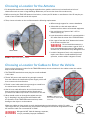
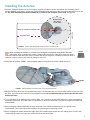
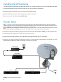
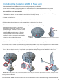
Installation Manual
Automatic
Multi-Satellite
TV Antenna
Model SK-7003
TRAV’LER® Shaw Direct Antenna
www.winegard.com/mobile
For Technical Services, email [email protected] or call 1-800-788-4417
Product Registration
Please register your Winegard product by filling out and returning the Product Registration Card
provided or by completing the online registration form at http://www.winegard.com/registration.
2452293
Before Installing the Antenna
You have selected the Winegard® TRAV’LER® automatic multi-satellite TV antenna. The TRAV’LER antenna will deliver
the ability to view multiple satellites at the same time with unmatched signal strength, the lowest travel height on
the market, maximum HD capabilities and easy to use functionality—just like you get at home. This manual provides
important information on the installation and operation of your TRAV’LER antenna on an RV. Please take time to read
the manual in its entirety before installing or operating your antenna.
Follow the instructions on this side if installing the TRAV’LER Shaw Direct antenna. For operation instructions, follow
the instructions on the reverse side of the manual.
Specifications
Depending on location and receiver type, the following satellites can be accessed with the TRAV’LER Shaw Direct
antenna during automatic operation: 107°, 111°.
Height of assembled unit: 9.75”
Width of assembled unit: 37”
Length of assembled unit: 46”
Width of mount base: 21”
Length of mount base: 24”
Unit Weight: 54 pounds (assembled)
Shipping Weight: 59 pounds (mount),
33.5 lbs (reflector, LNBF, & feed arm)
46″
23.5″
37″
″
21
″
24
FIGURE 1. Dimensions of Antenna
Safety Recommendations
Do not attempt to install this system in the rain or under
any wet conditions. Moisture may affect electronics and
void your warranty.
Do not paint this antenna. Painting the TRAV’LER
antenna will void your warranty.
Pay attention to the pinch points as the antenna raises.
The pinch points should be labeled on the antenna (see
fig. 2).
1
FIGURE 2. Pinch points (labeled)
Clearance Requirements
The arm of the TRAV’LER antenna extends 33” from the center of the base and may operate only 6” above the
surface to which the TRAV’LER antenna is mounted. To ensure you have adequate clearance for the TRAV’LER
antenna to safely operate, check that there are no obstructions taller than 6” within 33” of the center of the base.
Also, check that there are no obstructions (such as tree limbs) above the antenna that will prevent it from raising.
At its highest point, the antenna will extend to 39” above the roof to which it is mounted (see fig. 3).
FIGURE 3. Range of motion for TRAV’LER Shaw Direct antenna
Parts
Parts included with the SK-7003 are shown below. Note that the reflector, LNBF, and feed arm are packaged
separately as SKA-733 and are not pictured here.
Mount Base with 30’ Power/Control Cable and GPS Antenna
Mounting Screw (20)
Interface Box
Cable Entry Plate
Interface Box
Power Supply
24” AC power cord
30’ Black Coax Cable (2)
2
Choosing a Location for the Antenna
1. For best performance and to reduce signal acquisition time, park the vehicle on a level surface that is free of
obstructions such as trees or large buildings. Make sure you have a clear view of the southern sky.
2. Before removing the TRAV’LER antenna from its box, contact your RV dealer or manufacturer. Your RV may be prewired or have a reinforced area for this system.
3. Then, choose a location on the roof that meets the following requirements:
a. Offers enough support for a secure installation
b. Allows dish to raise and rotate without
interference from other roof-mounted equipment
c. Has a minimum roof space of 46” x 37” for
antenna (see fig. 4)
d. Lacks obstructions taller than 6” mounted within a
33” radius from the center of the TRAV’LER base
37″
e. Has a gap of less than 3/16” between the bottom
of the antenna and the roof
Do not install the antenna in a
location where a gap of 3/16” or
more exists between the bottom of the antenna
and the roof, as the antenna may damage the roof
WARNING
Center of Base
f. Is within 5 degrees of level, or the system may
require more time to locate satellites (for best
operation, must be within 3 degrees of level)
46″
FIGURE 4. Required roof space for antenna
Choosing a Location for Cables to Enter the Vehicle
Once you have chosen a location for the TRAV’LER antenna, choose a location for the cables to enter the vehicle.
Keep in mind the following:
1. The TRAV’LER interface box must plug into a well-ventilated
110 V outlet.
2. The 24” AC power cord must be long enough to extend
from the outlet to the interface box power supply, which will
then connect to the interface box.
3. The 30’ control cable must be long enough to extend from
the mount base to the interface box.
4. One 30’ coax cable will need to be run from the mount
base to each receiver inside the vehicle. Note that the
provided coax cables only include a connector on one end.
5. Wires should not be run through the striped area (see
fig. 5). Anything in the striped area will interfere with
the operation of the TRAV’LER antenna and may cause
damage to the object or to the antenna.
FIGURE 5. Marked area of
antenna where cables should
not be run
Make sure cables are long enough to reach their destination points inside the vehicle. For cable
runs longer than 30’, an extension may be purchased. Winegard recommends using Model CL-SK26
25’ extension cable. Do not exceed 55’ of cable!
WARNING
3
Winegard is NOT liable for damage, expenses,
or injury caused by improper installation.
CL-SK26
Sold Separately
Installing the Antenna
1. Place the TRAV’LER antenna on the roof where you plan to install it. On the mount base, the transition plate is
marked “FRONT” and “BACK.” Rotate the TRAV’LER antenna until the front of the mount base faces the front of the
RV. The TRAV’LER antenna must be installed on or parallel to the centerline of the coach. See figure 6.
No obstructions
taller than 6″
in a 33″ radius
Mount on or parallel to Centerline of RV
33″
Front of RV
Centerline of RV
FIGURE 6. Antenna (fully assembled) installed parallel to centerline of RV
TIP
When installing the antenna on a rubber roof, Winegard recommends using Model SKA-004
roller plate, which is designed to create a solid landing area for the roller. If not using this plate,
make sure that the roller does not come in contact with any rib supports or bubbles in the roof when in
operation. Failure to do so may result in damage to the roof.
SKA-004
Sold Separately
2. Verify that the marked “FRONT” of the transition plate is facing the front of the vehicle (see fig. 7).
“FRONT”
FIGURE 7. Marked “FRONT” of transition plate on fully assembled antenna
3. Mark the location where the nine screw holes will go. It is important that you can see these marks on the roof of the
RV. Then, move the mount base out of the installation area. It is recommended that you do not pre-drill the screw
holes at this time.
4. To prevent water from getting into the mount base, use a solid line of approved sealant to connect the marks in
the shape of the base. This step must be completed, or the unit will fail due to corrosion. Replace the TRAV’LER
antenna base.
5. Before using the supplied mounting screws, check with your vehicle manufacturer for any special screw
requirements. Then, screw the antenna base to the roof using nine mounting screws.
6. Run a solid bead of sealant around the edge where the transition plate meets the roof, making sure to cover each
screw head. Be careful not to get any sealant above the transition plate.
4
Installing the GPS Antenna
The GPS antenna is connected to the TRAV’LER antenna via a 6’ cable running to port E on the TRAV’LER mount base.
1. To install the antenna, find an open area at least 18” from either side of the mount base.
2. Place a small dot of sealant at the chosen location for the GPS antenna.
3. Place the GPS antenna on the sealant, and press the antenna into place.
4. Secure any excess cable. Do not cut the GPS cable.
Overall Setup
1. Drill a 1″ hole in the roof, and push the power/control cable and coax cables through the hole. Place the supplied
cable entry plate over the hole and cables, and screw the plate in place using eight of the supplied mounting screws.
Seal the plate and screw holes with approved sealant (not included).
Depending on the length of the cable on the roof, you may need to use cable clamps between the unit and the
cable entry plate. Clamping every 12–16” should eliminate any unnecessary cable movement.
TIP
2. Connect the power/control cable running from the mount base to the “DC OUT/ANT. COMM.” port of the interface box.
3. Connect the power supply to the “DC IN” port of the interface box.
4. Connect one end of the AC power cord to the power supply and the other end to a 110V outlet.
5. Connect a coax cable from the mount base to each receiver. The receiver(s) should already be connected to the TV(s).
Note that the provided coax cable only includes a connector on one end.
Power Supply
Interface Box
Receiver
FIGURE 8. Setup with fully assembled antenna
5
Receiver
GPS
Antenna
Installing the Reflector, LNBF, & Feed Arm
Note that the reflector, LNBF, and feed arm are packaged separately as SKA-733.
1. Press and hold “POWER” for two seconds to turn on the interface box. Wait until the interface box finishes
“connecting to antenna.” The TRAV’LER® antenna may enter the search routine after ten seconds. Pay attention to
the pinch points as the antenna raises!
2. Wait until the antenna has at least raised to a position in which the lift arms are perpendicular to the roof. Then, press
“POWER” and “SELECT” at the same time. The antenna should stop moving.
3. Unplug the interface box.
4. Insert the two longer screws into the top two holes in the front of the reflector.
5. Slide a wedge-shaped clamp onto each screw sticking out the back of the reflector.
6. Thread a nut onto each screw; make sure the nut is tight to keep the clamp from falling.
7. Align the two anchor posts on the back of
the reflector with the two notches in the skew
plate (see fig. 9). Then, set the reflector on the
skew plate; the reflector should be positioned
with the LNB arm at the bottom of the plate.
Carefully use the clamps on the back of the
reflector to hold the reflector in place (see fig.
10A); make sure that the thicker part of the
clamp is to the outside of the reflector.
Notches in
skew plate
Anchor posts
in reflector
FIGURE 9. Anchor posts and notches to align
8. Once the top screws and clamps are in place, install the lower screws and clamps.
9. With the bracket mounted securely, connect the four coax cables to the mount (see fig. 10B).
10. Locate the cable tie on the coax cables that you just connected to the mount. Place the p-clamp on the cables so that
it is just below this cable tie. If the cable tie is missing, install the clamp 14” from the end of the connectors.
11. Carefully screw this clamp to the front of the lift arm using the provided 5/16” screw (see fig. 10C). Warning: Be careful
not to strip out the hole for the 5/16” screw when you replace the clamp holding the coax cables to the arm. Do not
use a power tool. Do not overtighten this screw.
+
+
+
A
B
C
FIGURE 10. Installing reflector, LNBF, and feed arm. A, Reflector held on skew plate with clamps. B, Coax cables connected. C, P-clamp on lift arm.
12. Plug in the interface box.
13. Press and hold “POWER” for two seconds to turn on the interface box. Press the Power button again to stow the antenna.
6
WINEGARD MOBILE PRODUCTS LIMITED WARRANTY
(2 YEARS PARTS; 1 YEAR LABOR)
Winegard Company warrants this product against defects in materials or workmanship for a period of two (2) years from the date
of original purchase. During year one (1) of such warranty, Winegard Company will also pay authorized labor costs to an authorized
Winegard dealer to repair or replace defective products. No warranty claim will be honored unless at the time the claim is made,
Customer presents proof of purchase to an authorized Winegard dealer (to locate the nearest authorized Winegard dealer, contact
Winegard Company, 3000 Kirkwood Street, Burlington, Iowa 52601, Telephone 800-288-8094 or visit www.winegard.com). Customer
must provide proof of purchase with a dated sales receipt for the Winegard product to verify the product is under warranty. If the date of
purchase cannot be verified, the warranty period shall be considered to begin thirty (30) days after the date of manufacture.
If a defect in material or workmanship is discovered, Customer may take the product to an authorized Winegard dealer for service.
Customer must provide proof of purchase to verify the product is under warranty. If the product is brought to an authorized Winegard
dealer for service prior to expiration of year one (1) of the warranty period and a defect in material or workmanship is verified by
Winegard Technical Services, Winegard Company will cover the Winegard dealer’s labor charges for warranty service. The Winegard
dealer must contact Winegard Technical Services in advance for pre-approval of the service. Approval of the service is at the sole
discretion of Winegard Company.
Alternatively, Customer may ship the product prepaid to Winegard Technical Services (located at 3111 Kirkwood Street, Burlington,
Iowa 52601, Telephone 800-788-4417). Customer must return the product along with a brief description of the problem and provide
Winegard Technical Services with Customer’s name, address, and phone number. Customer must also provide proof of purchase to verify
the product is under warranty. If the product is returned before the expiration of the warranty period, Winegard Company will (at its
option) either repair or replace the product.
This Limited Warranty does not apply if the product has been damaged, deteriorates, malfunctions or fails from: improper installation,
misuse, abuse, neglect, accident, tampering, modification of the product as originally manufactured by Winegard in any manner
whatsoever, removing or defacing any serial number, usage not in accordance with product instructions or acts of nature such as
damage caused by wind, lightning, ice or corrosive environments such as salt spray and acid rain. This Limited Warranty also does not
apply if the product becomes unable to perform its' intended function in any way as a result of the television signal provider making any
changes in technology or service.
RETURN AUTHORIZATION POLICY
A Return Material Authorization (RMA) is required prior to returning any product to Winegard Company or Winegard Warranty Services
under this warranty policy. Please call our Technical Services Department at 800-788-4417 or send an email to warranty@winegard.
com to obtain the RMA number. Please furnish the date of purchase when requesting an RMA number. Enclose the product in a prepaid
package and write the RMA number in large, clear letters on the outside of the package. To avoid confusion or misunderstanding, a
shipment(s) without an RMA number(s) or an unauthorized return(s) will be refused and returned to Customer freight collect.
WINEGARD COMPANY DOES NOT ASSUME ANY LIABILITIES FOR ANY OTHER WARRANTIES, EXPRESS OR IMPLIED, MADE BY ANY
OTHER PERSON.
ALL OTHER WARRANTIES WHETHER EXPRESS, IMPLIED OR STATUTORY INCLUDING WARRANTIES OF FITNESS FOR A PARTICULAR
PURPOSE AND MERCHANTABILITY ARE LIMITED TO THE TWO YEAR PERIOD OF THIS WARRANTY.
In states that do not allow limitations on implied warranties, or the exclusion of limitation of incidental or consequential damages, the
above limitations or exclusions do not apply.
Some states do not allow limitations on how long an implied warranty lasts, or the exclusion of limitation of incidental or consequential
damages, so the above limitations or exclusions may not apply to you.
This warranty gives Customer specific legal rights. Customer may also have other rights that may vary from state to state.
SATELLITE RECEIVER WARRANTY:
See manufacturer’s limited warranty policy.
WS-MOBWARREV2
Rev. 1/10
Winegard Company • 3000 Kirkwood Street • Burlington, IA 52601 • 1-800-288-8094 • Fax 319-754-0787 • www.winegard.com
Printed in U.S.A. ©2013 Winegard Company Rev1 2/14 2452293
Winegard and TRAV’LER are registered trademarks of Winegard Company. Shaw Direct is a trademark of Shaw Satellite G.P.
Disclaimer: Although every effort has been made to ensure that the information in this manual is correct and complete, no company shall be held liable for any errors or
omissions in this manual. Information provided in this manual was accurate at time of printing.
Operation Manual
Automatic
Multi-Satellite
TV Antenna
Model SK-7003
TRAV’LER® Shaw Direct Antenna
www.winegard.com/mobile
For Technical Services, email [email protected] or call 1-800-788-4417
Product Registration
Please register your Winegard product by filling out and returning the Product Registration Card
provided or by completing the online registration form at http://www.winegard.com/registration.
2452293
Automatic Operation
The TRAV’LER antenna offers a simple one-button operation. Simply press “POWER,” and the antenna will
automatically begin searching for satellites. The instructions assume that the antenna is already in the stowed position.
1. Press and hold “POWER” for two
seconds or until the TRAV’LER
interface displays “POWER ON.”
2. Once the unit has been powered on,
release “POWER.”
connecting to
WINEGARD COMPANY
POWER ON
4. The TRAV’LER antenna will enter
the search mode as part of its
normal operation and will display
“Searching” on the bottom line.
antenna
5. The antenna will find its home
position and begin to look for a
satellite. Upon finding a satellite, the
antenna will fine-tune or “peak” on
the signal.
LG Shaw Direct
Searching...
7. Continue to page 2 if setting up the
receiver for the first time or if setting
up the receiver after moving the
receiver from the house to the RV. If
the receiver is already set up in the
RV, you are now ready to watch TV!
LG Shaw Direct
Home EL...
TIP
3. The interface screen will display
the type of satellite dish on the
top line.
LG Shaw Direct
Ready: Multi-Sat
6. In automatic search mode, the
TRAV’LER antenna will lock onto
two different satellites: 111° and
107°. The antenna will display an
asterisk for each satellite found.
LG Shaw Direct
*111 *107
To turn off the power to the TRAV’LER antenna after the antenna has
locked onto satellites, press “POWER” and “SELECT” at the same time.
Before traveling, make sure to press “POWER” and wait for the antenna to
start to power up; then press “POWER” again to initiate the stow sequence.
See below for information on stowing before traveling.
User Menu
The interface includes a user menu for some advanced features. The options most commonly used are the ability to change
the dish type, check software/hardware versions, change desired satellite configuration, or manually move the dish.
Improper use of the user menu could cause damage to the TRAV’LER antenna and/or vehicle. Follow
all instructions when entering the user menu for manual operation. See page 2.
WARNING
Ready to Travel?
The TRAV’LER antenna is not meant for use while traveling. To stow the unit when you are ready to travel, press
“POWER” one time. The unit will stop what it is doing and return to the stowed position. The TRAV’LER interface will
not turn off unless the TRAV’LER anetnna is successfully stowed. Visually inspect that the antenna is in the stowed/
travel position before traveling. Do not move the vehicle until the TRAV’LER antenna is stowed.
Emergency Manual Stow
If unable to stow the TRAV’LER antenna, it may be necessary to use emergency manual stow. Emergency manual stow
is meant as a last resort and is not meant for common usage! To use emergency manual stow, unplug the interface
box. Then, remove the black plastic bolt from the back of the mount. Insert a 3/8th socket extension into this auxiliary
drive. Turn the auxiliary drive clockwise to lower the unit. Do not use a drill!
Emergency Power Off
The antenna comes with an emergency power off feature. To activate it, press and hold “POWER” and then press
“SELECT” while still holding “POWER”. The TRAV’LER antenna will stop and turn off. If the emergency power off
feature is used, the antenna may not be in a safe position for travel. Do not move the vehicle until the unit is stowed.
1
Manual Operation
The TRAV’LER antenna is a versatile satellite antenna and can be manually set to find many different satellites individually.
This function is rarely used. The instructions assume that the antenna is already in the stowed position. Note: Diagnostics
and Installation menus are not required for normal operation and should only be entered by a trained professional.
1. Press and hold “POWER” for two
seconds or until the TRAV’LER
interface displays “POWER ON.”
Then, press and hold “ENTER for
two seconds.
WINEGARD COMPANY
POWER ON
4. In the Search menu, choose from
the following: Multi-Sat Mode
(normal search mode), Manual 111,
Manual 107, Main Menu (returns to
the user menu) or Exit (enters the
search routine).
Press the Select button to cycle
through satellites until the asterisk
is next to the satellite you wish to
find. Press “ENTER” to confirm the
selection.
Multi-Sat Mode*
Manual 61
2. The interface will ask if you wish
to enter the user menu. Press the
Select button to choose “Yes,”
and then press the Enter button to
confirm the selection.
3. The user menu consists of
four choices: Search Mode,
Diagnostics, Installation, and Exit.
Press the Enter button to choose
Search Mode.
Enter User Menu?
Search Mode*
Diagnostics
*Yes No
5. The interface will ask you to
confirm the change. Press
“SELECT” to move the asterisk
to “Yes.” Then, press “ENTER” to
confirm the selection.
The TRAV’LER interface will
then acknowledge which satellite
has been selected. Press the
Enter button.
6. The interface will ask if you want
to turn the power off. Press the
Enter button to choose “No” and
start a new search for your chosen
satellite. Press “SELECT” then
“ENTER” to choose “Yes” and turn
off the antenna.
The TRAV’LER antenna will remain
in manual mode until you select
“Multi-Sat Mode” again.
Manual ##
Selected
Power OFF?
*Yes No
Connecting the Shaw Direct Receiver
1. Connect your Shaw Direct receiver to the TV using the appropriate audio and video cables. (Refer to your television
user manual for the best audio/video connections).
2. If you have not chosen a programming package for your Shaw Direct system or added this receiver to your existing
Shaw Direct account, please call 1-888-554-7827 prior to using your Shaw Direct receiver for the first time.
3. Ensure that your Shaw Direct receiver is connected to power.
4. Locate the coaxial feed coming from the TRAV’LER system.
5. Connect the satellite feed to the coaxial input labeled with the symbol of a satellite dish.
6. Power on the Shaw Direct receiver and television. If your TRAV’LER system is properly tuned and receiving signal,
the satellite dish icon on the front of the Shaw Direct receiver will be highlighted in green.
If the TRAV’LER system is stowed or not tuned to the Shaw Direct satellites, the satellite icon on the front of the Shaw
Direct receiver will appear in red. Turn on the TRAV’LER unit or troubleshoot as needed to reachieve positive signal.
If your Shaw Direct system is disconnected from power for an extended period of time or has been recently moved
from another location, you may need to have your Shaw Direct system reauthorized. This can be determined when
you receive a green (positive) signal but cannot receive video on a subscribed channel.
2
To initiate a signal refresh, call 1-888-554-7827, then select “Self-Serve”, “Technical Support”, followed by “Signal
Refresh” from the telephone menu options.
For changes to Shaw Direct programming or to purchase new Shaw Direct equipment, visit shawdirect.ca or call
1-888-554-7827.
Note that the TRAV’LER antenna will find the satellites without the receiver installed.
Troubleshooting
ANTENNA CONNECTION FAILED
Check the data cable connection on the back of the interface box. It may not be
connected properly.
EL HOME FAILURE
Something is preventing the mount from raising as it attempted to find the
HOME position. Look for obstructions if the unit has recently been manually
raised or if the electronics have been replaced. The calibration may need
to be reset. Contact Winegard Technical Support at [email protected] or
1-800-788-4417.
AZ MOTOR STALLED
Something is preventing the mount from rotating; look for obstructions. If
there is no obvious obstruction, contact Winegard Technical Support at help@
winegard.com or 1-800-788-4417.
EL MOTOR STALLED
Something is preventing the mount from raising or lowering; look for
obstructions. If there is no obvious obstruction, contact Winegard Technical
Support at [email protected] or 1-800-788-4417.
SK MOTOR STALLED
Something is preventing the reflector and LNBF from rotating; look for
obstructions. If there is no obvious obstruction, contact Winegard Technical
Support at [email protected] or 1-800-788-4417.
STOW FAILURE
ANT NOT STOWED
The TRAV’LER antenna is not stowed. Do not try to move the vehicle. Try to
stow the TRAV’LER antenna again. If it fails again, check for obstructions.
STOW FAILURE
STOW UNKNOWN
Check the data cable connection on the back of the interface. It may not be
connected properly.
AZ MOTOR RUN REVERSE
Contact Winegard Technical Support at [email protected] or 1-800-788-4417.
EL MOTOR RUN REVERSE
Contact Winegard Technical Support at [email protected] or 1-800-788-4417.
SK MOTOR RUN REVERSE
Contact Winegard Technical Support at [email protected] or 1-800-788-4417.
AZ MOTOR RUNAWAY
Contact Winegard Technical Support at [email protected] or 1-800-788-4417.
EL MOTOR RUNAWAY
Contact Winegard Technical Support at [email protected] or 1-800-788-4417.
SK MOTOR RUNAWAY
Contact Winegard Technical Support at [email protected] or 1-800-788-4417.
NO LNB VOLTAGE
The TRAV’LER antenna is not seeing the required 12–18 VDC needed to power
the LNBF. Check the coax connections. If these are all connected properly,
contact Winegard Technical Support at [email protected] or 1-800-788-4417.
UNKNOWN ERROR ######
Contact Winegard Technical Support at [email protected] or 1-800-788-4417.
C MOTOR NOT FOUND
Contact Winegard Technical Support at [email protected] or 1-800-788-4417.
ANTENNA WILL NOT
AUTOMATICALLY STOW.
See emergency manual stow instructions in the operation manual.
Weather and vehicle location can impact the ability of the TRAV’LER antenna to locate all of the required satellites.
Obstructions such as buildings or tree limbs can block the satellite signals and prevent the TRAV’LER antenna from
successfully locating all of the satellites during automatic operation. Make sure you have a clear view of the southern sky.
3


![ac circuit breaker panels [without meters] installation - thornam-shop](http://vs1.manualzilla.com/store/data/006886941_1-35cc363a8b64d2c248bc8206f0066550-150x150.png)