1
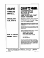
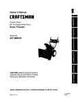
MANUAL
CRAFTSMAN®
i Caution:
Read and Follow
_ All Safety Rules
and Instructions
i Before Operating
This Equipment
8
HORSEPOWER
26" DUAL STAGE
TRAC-PLUS
120V. ELECTRIC START
SNOW THROWER
• Assembly
Operatzon
Maintenance
• Service and Adjustments
- RePair Parts
SEARS,. ROEBUCK AND CO., Chicago, IL 60684 ,U.S.A.
f
.
i r •
n
i| mini
li
: i
i
•
i
SAFETY RULES
WiRE WHERE
IT CANNOT CONTACT
SPARK PLUG TO PREVENT
CAUTION:
ALWAYS DISCONNECT
SPARK PLUG WIRE AND PLACE
ACCIDENTAL
STARTING
WHEN SE'I-I'ING-UP,
TRANSPORTING,
ADJUSTING
OR MAKING REPAIRS:
A
IMPORTANT
SAFETY STANDARDS
REQUIRE
OPERATOR
PRESENCE
CONTROLS
TO MINIMIZE THE
RISK OF INJURY. YOUR SNOW THROWER
IS EQUIPPED
WITH SUCH CONTROLS.
DO NOT
ATTEMPT TO DEFEAT THE FUNCTION
OF THE OPERATOR
PRESENCE
CONTROL
UNDER
ANY CIRCU MSTANCES.
BEFORE USE
•
Read the Owner's Manual carefully. Be thoroughly familiar with the controls arid the proper
use of the snow thrower. Know how to stop the
show thrower and disengage the controls
quickly.
:o
Do notoperatethesnowthrowerwithoutwearing adequate winter outer garments. Wear
footwear that will improve footing on slippery
FUEL SAFETY
,"
•
Handle fuel with care; it is highly flammable.
•
•
Use an approved fuel container.
Check fuel supply before each use, allowing
space for expansion as the heat of the engine
and/or sun can cause fuei_to expand.
Fill fueltankoutdoorswith
extreme care. Never
fill fuel tank indoors.
'0
D
Replace fuel tank cap Securely and wipe up
spilled fuel.
•
Never remove fuel tank cap or add fuel to a
running engine or hot engine.
Never store fuel or snowthrcwer with fuel in the
tank inside of a building where fumes may
reach an open flame or spark.
surfaces.
o
Keepthe area of operation clearof all persons,
particularly small children, and pets.
•
Thoroughly inspect the area where the snow
thrower isto be used and remove all doormats,
sleds, boards, wires, and other foreign objects.
=
•
Use extension cords and receptacles as specified by the manufacturer for all .snow throwers
with electric drive motors or electdc starting
motors.
•
Use only attachments and accessories approvedbythe manufacturerofthesnowthrower
(such as tire chains, electdc start kits, etc.)
OPERATING SAFETY
• _ Never allow children or young teenagers to
operate the snow throwerand keep them away
while it :is operating. Never allow adults to
operate ,the snow thrower without proper in-_
°
struction. Do not carry passengem.:
•
Never operate the snow thrower without good
visibility or light. Always be sure of yourfooting,
and keep a firm hold on the handles. Walk;
never run.
This snow thrower is for use on sidewalks,
driveways, and other ground level surfaces.
CAUTION should be exercised while using on
steep sloping surfaces. DO NOT USE SNOW
THROWER
ON
SURFACES
ABOVE
GROUND LEVEL such as roofs of residences,
•
I
•
•
•
garages, porches or other such structures or
buildings,
•
Check shear bolts and other bolts at frequent
intervals for proper tightness to be sure the
snow thrower is in safe working condition.
•
Disengage all clutches and shift into neutral
before starting the engine.
Always wear safety glasses or eye shields
during operation orwhile performing an adjust,
ment or repair to protect eyes from foreign
objects that may be thrown from the snow
thrower.
Exercise extreme caution when operating on
or crossing g ravel ddves, walks, or roads. Stay
alert for hidden hazards or traffic.
Do not put hands or feet near or under rotating
parts. Keep clear of the discharge opening at
all times.
Exercise caution to avoid slipping or falling, especially when operating in reverse.
Do not clear snow across the face of slopes.
Exercise caution when changing direction on
slopes. Do not attempt to clear steep slopes.
•
•
Adjust the snow thrower height to clear gravel
.... or crushed rock surface.
• _Let engine andsnow thrower adjust to outdoor
..... temperatures before starting to clear snow.
Never operate the snow thrower without proper
guards, plates or other safety protective devices in place ......
/i
2
SAFETY RULES
• r:'
•
'
Never operate the snow thrower near glass
enclosures, automobiles, window wells, dropoffs, and the like without proper adjustment of
the snow discharge angle. Keep children and
pets away.
• .... Never operate the snow thrower at high transport speeds on slippery surfaces. Look behind
and use care when backing.
•
REPAIRIADJUSTMENTS SAFETY
•
..e
. Never directdischarge at bystanders or allow
- anyone in front of the snow thrower.
Do not run the engine indoors, except when
starting the engine and for transporting the
snow thrower
in or out of the building. Open the
=
,
outside doors; exhaust fumes are dangerous
.(containing CARBON MONOXIDE, an ODORLESS and DEADLY GAS).
•
Take all possible precautions when leaving the
........snow thrower unattended. Disengage the au-
"
•
:" ger/impeller, shift to neutral, stop erigine, and
• .: remove key ....
....
•-_ Do not overload the machine capacity by attempting to clear snow at too fast a rate.
SAFE STORAGE
•
Always refer to Owner's Manual instructions for
important details if the snow thrower is to be
stored for an extended period.
•
Disengage power to the auger/impeller when
snow thrower is transported or not in use.
•
•
After striking aforeign object, stop the engine
(motor), remove the wire from the spark plug,
disconnect
the Cord on electric motors, thor=
•
oughly !nsPect the snow thrower for any damage, _and.repair the damage before restarting
and Operating th_ snow thrower.
If the snow thrower should start to vibrate
abnormally, stop the engine (motor) and check
immediately for the cause. Vibration is generally a warning of trouble.
Stop the engine (motor) whenever you leave
the operating position before unclogging the
auger/impeller housing or discharge guide,
and when making any repairs, adjustments, or
inspections.
•
When cle'aning, repairing, or inspecting, make
certain the auger/impeller and all moving parts
have stopped. Disconnectthe spark plug wire
and keep the wire away from the plug to pre-;vent accidental Starting. "
:
-
•
Never attempt to make any adjustmentswhile
the engine is running (except when specifically
recommended by. manufacturer,).
•
Maintain or replace safety and instruction labels, as necessary.
Run the snow thrower a few minutes after
•
Never store the snow thrower with fuel in the
fuel t_.nkinside abuilding whereignition sources ...........
are present such. as hot water and space ....:
heaters, clothes dryers, and the like. Allow the .....
engine to cool before storing in any enc!osure .......
throwing
snow to prevent
auger/impeller'
UNCLOGGING DIS-
i ¸&
LOOK FOR THIS SYMBOL TOPOINT OUT
IMPORTANT SAFETY PRECAUTIONS. IT
MEANS--ATTE NTION!!! BECOME •A LE RT!!!
YOUR SAFETY IS INVOLVED.
....
,
,
•
freeze-up of the
. •
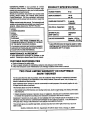
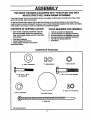
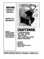
PRODUCT SPECIFICATIONS
CONGRATULATIONS on your purchase of a Sears
Craftsman Snow Thrower. tt has been designed;engineered and manufacturedto give you the best possible
dependabilityand performance.
Should you experience any problem you cannot easily
remedy, please contact your nearest Sears Service
CenterlDepartrnent. We have competent, we,-trained
techniciansand the proper toolstoservice orrepair this
HORSE POWER:
8 hp
DISPLACEMENT:
19.43
cu. in.
i
unit.
JJ
GASOUNE
_
PId_zseread and retainthis manual. The instructionswill
enable youtorassembleand maintain your snowthrower
pr0pedy. .AIways observe the "SAFETY RULES."
CAPACITY:
III
=
Ill
i
,,
4 quarts
Unleaded
i
iii
OIL (26 oz. Capacity):
10W-3O
(sw - 3o)*
MODEL
NUMBER 536.885910
i
ii
SPARK PLUG :
(GAP .030 in.)
SERIAL
NUMBER
DATE OF
PURCHASE.
iiii
Champion
J8C
H
VALVE CLEARANCE:
THE MODELAND SERIAL NUMBERS WILL BE
FOUND ON A DECAL ATTACHED TOTHE REAR
OF THE SNOW THROWER HOUSING.
i
Intake: .010 In.
Exhaust: .010 In.
* S,A.E 5W-3O motor oi! may be used to make
YOU SHOULD RECORD BOTH SERIAL NUMBER
AND DATE OF PURCHASE AND KEEP IN A SAFE
PLACE FOR FUTURE REFERENCE.
start!ng easier in areas where temperature
consistently 20 ° F. or lower.
is
MAINTENANCE AGREEMENT
A Sears Maintenance Agreement is available on this
product. Contact your nearest Sears Store for details.
-'=CUSTOMER RESPONSIBILITIES
• Read and observe the safety rules.
• Followa regular schedule in maintaining,cadng for and using your snow thrower.
• Followthe instructionsunder =Maintenance" and "Storage'sections of this owner's manual.
i
i
]i
illilili
1 ii
TWO YEAR LIMITED WARRANTY ON CRAFTSMAN
SNOW THROWER
For two years from the date of purchase,when this Craftsman Snow Thrower is maintained, lubricated
and tuned-up according to the instructionsin the owner's manual, Sears will repair, free of charge, any
defect in material and workmanship.
If this Craftsman Snow Thrower is used for commercial or rental purposes, this warranty applies for only
90 days from the date of purchase.
This warranty does not cover the following:
• Expendable items which become worn during normal use, such as s__rk plugs,tire chains; drive belts
and shear pins.
= Repairs necessary because of operator abuse or negligence, includingbent crankshaftsand the failure
to maintain the equipment accordingto the instructionscontained in the owner's manual.
WARRANTY SERVICE IS AVA1LABLEBY RETURNING THE CRAFTSMAN SNOW THROWER TO THE
NEAREST SEARS SERVICE CENTER/DEPARTMENT IN THE UNITED STATES. THIS WARRANTY
APPLIES ONLY WHILE THIS PRODUCT IS IN USE IN THE UNITED STATES.
This warranty gives you specificlegal rights, and you may also have other rights which may vary from
state to state.
•.:
SEARS, ROEBUCK AND CO. Department 731CR-W, Sears Tower, Chicago, IL 60684
,,,,,,
,,
,,
iii
i
i
4
i iiii ii iii
_
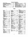
TABLE OFCONTENTS
SAFETY RULES ........................................
2,3
PRODUCT SPECIFICATIONS ...................... 4
CUSTOMER RESPONSIBILITIES ............ ._4
WARRANTY.... .............................................
.4
TABLE OF CONTENTS .............................. -.5
INDEX .........................................
.................. 5
ASSEMBLY ................................................
6-9
OPERATION ..........................................
10-15
MAINTENANCE ........................
16-17
SERVICE AND ADJUSTMENTS ........... 18-24
STORAGE ...................................................
25
SERVICE RECOMMENDATIONS
.............. 26
TROUBLE SHOOTING ............................... 27
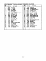
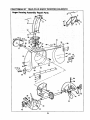
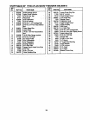
REPA! R PARTS (SNOW TH ROWER)...28-36
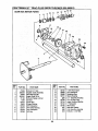
REPAIR PARTS (ENGINE} .................... 37-40
PARTS ORDERING/SERVICE.....
Back Cover
INDEX
A
F
Operation:
Adjustment:
Fuel, Type .................... ,......;.......4, 12
Engine Controls ....... ;L'.;10, 11, 13,14
Auger ................ :................. ;.......... 19 • Fuel, Storage ............... ...:;:..;,;..: 12, 25 _
Operating Snow Thrower...11, 12, 15
Belt ...................... .:....................... 19
Operating Tips ............................... 15
o FrictionWheel:
Belt Guide .........................
:21
Adjustment.................................... 21
Starting the Engine, Electric .:........ 13
Cable .................... ;........................ 19 :
Replacement ................................. 22
Starting the Engine, Reoofl....L ...... 14
Carburetor ..................................... 24
G
: Snow Thrower Controls ......... ;.. 10-12
Fdctbn Wheel ................................ 2t
Geam:
Weight Transfer System ................ 12
Spark Plug ..................................... 24
Auger Gear Box ...................... 16, 17
Track.............................................. 23
P
Hex Shaft ....................................... 16
H
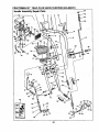
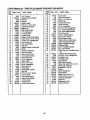
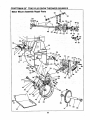
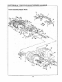
Parts ............................................ 28-40
Traction and Auger ........................ lg
Assembly:
Primer Button ................. 10, 11, 13, 14
Handle, Upper and Lower ................ 7
R
Crank Assembly ... ........................... 8 :::;.Headlight.; ....... ;....... ;;;;;_.:.;_;:.;.;;;;.9. I0
Repair/Replacement Parts .......... 28-40
Headlight ......................................... 9
" Height Adjust Skids ::::::::::::::::::::::: t8
ShifterLever ,.; ......;.......... ;;..;.:;.:;;;.9 ....... Hex Shaft. ......... :::;:.:.:.:::::::..:.:,.16, 17 ..... Recoil Starter ...................... ;...:;....... 14
Skid Height Adjustment ............. 7, 18
I
Replacements:
Auger Shear Bolt ....i ...................... 23
Unpacking........................................ 7
Ignition, Key.................... 10, 11, 13, 14
Belts......................................... 20, 21
e
,
index ........_......................................... 5
Belts:
L
FrictionWheel ............................... 22
Adjust Belts..... ;:_.......;.:,................. 19
Levers:
S
Belt Guide Adjustment................... 21
Auger Drive clutch ........ 7, 10, 11, 19
Safety Rules.:.. ............................... 2, 3.
Belt Maintenance..: .......::::............. 16
Choke ,. .............. ......... 10, 11, 13, 14
Service and Adjustments:
Replace Belts .......................... ;20, 21
Sh_e_ ................................. 9, 10, 11
Auger Housing Height ............... 7, 18
C
Throttle Control ...:........ 10, 11, 13, 14
• Auger Shear Bolt ........................... 23
Cables,Clutch ........................... 7, 9, lg
Belts ......................................... 19-21
Traction Drive Clutch ..:..7, 10, 11, 19
Carburetor:.................................. 24,25 :: : Lubrication:
Belt Guide ....................... L..;......... .21
Chain _....:.:........... ;:,:::..:..:
16 •
Auger Gear Box ............................ 17: :::i:Belt Replacements .......... ...;....20, 21
Choke ........;::::::::;:::::::;:::::....... I0,. 1I, 13
Auger Shaft ............... ;.............. 16, 26
Cable .............................. ...,.. 7, 9,_19
Clutch, Levers .......... :.......... ;;;.;;.10, 11
Chain and Sprockets ............... 16, 26
Carburetor ............................... 24,25
Controls:
Chart. ............................................ 26
FrictionWheel .......................... 21, 22
Engine .:.:L._............ LI" 10, 11,13, I4
Engine ..................................... 12, 17
Spark Plug .......... :;......................... 24
Snow Thrower ............................... IO
Hax Shaft and Gears ..................... 16
Track .............................................. 23
Crank:
: Weight Transfer System .......... 12, t6
Service Recommendations ............ 26
Adjusting Rod ............................ 8, 18
M
:
Spark Plug................................. 17,24
Assembly ......................................... 8
Maintenance:
Specifications ..................................... 4
Operation ....................................... 11
Agreement ....................................... 4
Speed Governor ........ ._,.................... 24
Customer Responsibilities.................. 4
Auger Gear Box ................... .......... 17
Startingthe Engine:
Auger Shaft ......................... , ......... 16
Electric Start .._........._.................... 13
Drive, Auger ....... ._............................ 11
Chain and sprockets.......... _........... 16
ReCoilStart ...;................................ 14
Drive, Traction .;:,...... .................... 11
Engine .................................. ......... 17Stoppingthe Engine .......... ;..11, 13,14
Deflector, Snow Chute ..................... 11
General Recommendations ........... 16
Stopping the Snow Thlower ............ .11
Hex Shaft and Gears ..................... 16
Shipping Carton ............................. 6, 7
E.
Weight Transfer System ................ 16
Skid Height ......................... ;..... ..... 7, 18
Engine:
• O
Shifter Lever................................. 9-11
Control......................... 10, 11, 13, 14
Oil:
Shear Bolts ...................................... :23
Oil Cap .... ................................. 12, 17
Engine ................................ 4, 12, 17
Storage ............................................ 25
Oil Change ............................. ..,.. 17
Extreme Cold Weather ......._...:.12,17
_
T
Oil Level.....: .......... ;............ :.:... 12, 17
Storage :..... ..... .i.L._ .... _... ......,..25
Table of Contents ..:..;.._................. ..5
Oil Type ............................... 4, 12, 17
Type ..................................
4, 12, 17
Trouble Shooting Chart .................... 27
Speed Governor ............................ 24
Tools for Assembly ....................... ._6
Starting,Electrically....................... 13
Traction Drive Belt .................... 19,21
Starting,Manually .......................... 14
Track Adjustment ............................ 23
Storage .......................................... 25
w
Warranty..;.. ......:..... ;.............. :......... :_4
Weight Transfer System .......... 12,_18
,,
,,,
LI
i
MBLY
i ii
i
H
i
i,
,,,
i
, •
THIS SNOW THROWER IS EQUIPPED WITH "TRAC-PLUS" AND ONLY
MOVES EFFECTIVELY WHEN ENGINE IS RUNNING
ff yoursnow thrower must be moved withoutthe aid of theengine, it willbe easier to pull the snowthrower backward by the handles, ratherthan pushing.
On startUp,the track drive system may be tight and wni loosen up as the _ow thrower is used. Alter first use,
checkthe track for tension and adjust if necessary. See the Track Adjustmentparagraph in the Service and Adjustmentssectionof this manual. Check track adjustment and fasteners regularly.
CONTE_S
OF SHIPPING CARTON r,'
TOOLS REQUIRED FOR ASSEMBLY
1 - Snow thrower completely assembled except for
the crank assembly, shifter lever assembly and
knob, andrthe upper handle, whichis in the folded
down position.
12221.
1-
Parts Bag Containing:
Owner'sManual (Not Shown)
1- ElectdcStarter Cord 9.5 Ft (not shown)
PartsShown Below:
Knife (to cut cartonand plastiaties)
1/2 inchWrenches (or adjustablewrenches)
9!16 inch Wrenches (or adjustablewrenches)
3/4 inchWrenches (or adjustablewrenches)
Pair Pliers (to spread cotter pin)
ScreWdriver
CONTENTS OF PARTSBAG
ii
,
i |
©
2 - 3/8 in. Flatwashers
1-3/8
*2 - Spare Spacers
In. Hex Nut
II
1-3/8 - 16x2
"2- 1t4-20x 1 _3!,$ In.
Hex Head Boit_
In. Hex Head Bolt
*2 - Spare 1/4 - 20 Locknuts
1-3/8 In. Lockwasher
1 - KnobWithThreads
>
2 - Cablelies
*Non-Assembled Parts
6
Figure
I showsthe
snowthrower
in the shippingposition.
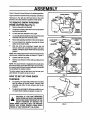
LOWER HANDLE
Figure2 showsthesnowthrowercompletely assembled.
Reference to the right and left hand side of the sndw
thrower isfrom the operator's position at the handle.
TO REMOVE
SNOW
CRANK
CLUTCH
CABLE
THROWER
FROM CARTON (See Fig 1)
•
Remove top pallet and discard.
•
Cut all four comers of the carton from top to bottom
and lay the panels fiat.
•
Cut the cable ties attached to the auger.
•
Cut and discardthe plasticties that securethecrank
assembly and place the assembly aside.
•
Removethe packing materialfromthe controlpanel.
•
Cut and discard the packing securing the clutch
cables to the lower handle.
UPPER
HANDLE
. ASSEMBLY
FIG. 1
With two 9t16 inch wrenches, loosen (do not
remove) both bolts securing the upper and lower
handles. Swingthe upperhandle intothe operating
position.
NOTE: ifthe cables havebecome disconnectedfrom the
clutch levers, reinstallthe cables as shown in Figure3.
•
Tighten bothbolts securely.
Roll the snow thrower off the skid by pullingon the
handle.
NOTE: This snow thrower is equipped with a track drive
and can be hardto pushwhen the engine is not running.
It iseasier to pullthe snowthrower backward ifit mustbe
moved withoutthe engine running.
The drive system may be tight when you first use your
snow thrower. It loosens up as you use it.
FIG. 2
HOW TO SET UP YOUR SNOW
im
i
THROWER
•
For packing,the height adjustskids were mounted
with the bottom lip tumed inward. Remove skid
mounting nuts (Fig. 2) and remount withthe lip
outward.
DRIVE
LEVER
To adjustthe skidheightfordifferent conditions,see
To Adjust Skids Heights paragraph on page 18.
CAUTION:
IF YOU ARE REMOVING
A
SNOW
FROMRAISE
ANY ROCKY
OR UNEVEN
SURFACES,
THE FRONT
OF THE
SNOW THROWER BY MOVING THE
SKIDS DOWN. THIS WILL HELP TO PREVENT
ROCKS AND OTHER DEBRIS FROM BEING
PICKED UP AND THROWN BY THE AUGER.
FIG. 3
7
BLY
I
]
I
i
il
IIIII
mR
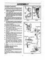
TO INSTALL THE UPPER HANDLE AND
CRANK ASSEMBL
ii
I_OHT HANOLE
/
On the rightside of the handle, installand secure the
following parts (found in parts bag) in the lower
handle hole as shown in Fig. 4A:
1 - 3/8"x 2, bolt
_- RLAIWASHB_
2 - 3/8" flatwashers & 1 - 3/8" iockwasher
1 - 3/8" nut
•
•
•
•
Remove the 3/8" nylon locknut and flatwasher from
the eye bolt assembly (onthe chute crank assembly).
the tightnessofthe two 3/8" jam nuts.The jam
nu_sshouldbe 3 inches from the end of the eye
bolt (RD, 4B inset).
H
FIG. 4A
Install eye bolt throughlower hole on the left hand
sideof the handle (See Rg. 4B).
Installthe 3/8" flatwasherand the 3/8" nylon Iocknut
looselyon the eye bolt as shown in Fig. 4B.
_Rernovethe plasticcap,the cotterpin andthewasher
fromthe wormed end of the crank assembly and set
aside (See Fig. 5).
AO.IUSl"NUTSTO M(W_
gi OROUT
o_: Rotate the notched section of the discharge chute
toward the crank-adjustingrod.
•
EYEBOLT
InStallthe wommd end of the-crank through-the-hole
in the adjustingrod and secure theend with the fiat
washer and cotter pin, as shownin Fig. 5.
•
Bendthe ends of the cotter pin around the rod and
reinstallthe plasticcap.
•
Tightenthe eye boltinstalled earlier, keeping eye in
linewiththe rod while tighteningthe inside ncure]y.
•
On the eyebolt, tighten theoutside 3/8" jam nut up
agalnst_theother 3/8" jam nut and retum the boot
over the adapter (See Fig. 4B).
•
Rotate the chute crank fully clockwise and fully
counter, clockwise. The discharge chute should
rotate fully to the outer diameter of the worm and
should clear approximately 1/8" (see Fig. 5). If the
chute crank needs to be adjusted, go to the
Service and Adjustmentssectionon page 18. Screws
securingchuteclips at the base of the chute should
be slightlyloosefor easy rotation.
NOTE: Be sure the crank does not touchthe sideofthe
engine or the cover will be scratched.
I
ENOOF
Bile BOLT
FIG. 4B Inset
ii
i
FIG. 4B
RG. 5
8
ii
iii
,
,,ll j
m
Jl_q
.||.n
i
i
i
i
i
n n,
,
...........................
MBLY
i
i
i
III
II IIIItl
III
lilt
lilt
III
t
t
TO INSTALL HEADLIGHT
The headlight is mounted on the right side of the upper '
handle. It is installedupsidedownfor shippingpurposdst'_
•
Remove the nut on the pivot bolt (Fig, 5A), place
headlightin correctposition(as shown in Fig. 5B and
in Fig 2), and retightennut.
•
Tie the headlight cable to upper and lower handles
with the plasticcable tiessupplied inthe parts bag by
threading the pointed ends of each tie through the
square end and pullingtightly around the headlight cable and the handle.
NOTE: One side of the plastictie has small notchesin it,
whilethe otherside is smooth.The notched side mustbe
ontheinsideofthe Ioopwhichisformedwhentha endsare
put together,
RG. 5A
•
Tryto loosenthe cable tie. ff itcan be loosened,it has
been attached with the smooth side on the inside of_:
the loop.Removethecabletieandreverseitsdirection.
•
Cut off excess plastictie.
FIG. 5B
TO INSTALL THE SHIFTER LEVER
Stand the snow thrower up on the,frontof the auger
housing,as shownin Figure 6A.
_
r
•
Cut the plastic tie which holds the shifter lever
assembly to the shiftbracket (Fig. 6B).
•
Remove the Iocknut, washer, spring and bolt
(Fkjure
6D).
•
ReposiUon the shifter
leverintothe slotin the
control
panel,as shown inFig.6(3,and reinstall
the
bolt,
spring,
washerand thelocknut.
•
Tighten
thelocknut
until
I/8"to3/16"(2or3 threads)
ofthebolt
protrude
pastthelocknut.
•
A
PLASTICTIE
SHmTER
LEVER
B
CONTROL PANEL
Thread the shifterlever knob onto the threaded end
of the shifterlever until itis tight (Fig. 6D).
SHIFTER KNOB
•
Move the shitter lever through all the speeds to
ensure proper tension of the spring, tf the shifter
lever sticks in any of the notches, loosen the
Iocknut1t4 turn at atime untgthe shifterlever moves
freely.
e: Return the snow thrower to the normal operating
position.
C
TO CHECK/ADJUST CLUTCH
CONTROL CABLES
The contro!cables attachedto the auger clutchlever and
tractionclutchlever may need to be adjusted beforeyou
use yoursnow thrower.
WASHER
1/S TO 3/16 INCH OF
EXPOSED THREADS
Fort:instructionson checking or adjusting=the control
cables,see ToAdjustClutchControlCables paragraphon
page 19.
FIG. 6
9
D
//
• ii1•11 i
i •
i
........
,................,
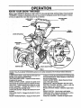
KNOWYOUR:SNOW
OPERATION
THROWER
.......
READ THIS OWNER'S MANUAL AND SAFETY RULES BEFORE OPERATING YOUR SNOW
TH ROWER. Compare the illustrationswith your snow thrower to familiarize yourselfwith the location of vadous
controls and adjustments.
....
'Save this manual for future r_emn_
AUGER DRIVE
LEVER
i
TRACTION DRIVE
LEVER
LEVER
......
. CHUTE DEFLECTOR
:
WBGHT
TRANSFER
DISCHARGE
CHUTE
PRIMER BUTTON
BUTTON
IGNITION
KEY
REOOIIL
STARTER
HANDLE
CHOKE CONTROL
THROTTLE CONTROL
SCRAPER BAR
FIG. 8
I
IIJIItUI
I
•
I
I
111111111
I
SEARS TRAC-PLUS SNOWTHROWERS conform to the safety standardsof the American National Standards
Institute.
AUGER DRIVE LEVER - Starts and stopsthe auger and
impeller(snow gathering and throwing).
TRACTION DRIVE LEVER - Propels the snow thrower
forward and in reverse.
SPEED SHIFTER LEVER - Selects the speed of the
L
_
.......
ii
LIL
i i
iron
f
i
conditions, to keep the snow throwerfrom climbing drifts
and hard-packed snow. When released, it eases transport of the snow thrower.
HEIGHT ADJUST SKIDS - Adjuststhe ground clearance of the auger housing.
IGNITION KEY- Must be insertedto start the engine.
ELECTRIC STARTER BUTTON - Used to start;the
engine using the 120 V electricstarter.
RECOIL STARTER HANDLE - Starts the engine manually.
*
CHOKE CONTROL - Used to start a cold engine.
PRIMER BUTTON - Injectsfuel directlyintothe carburetor manifoldfor fast starts in cold weather.
THRO'I-rLE CONTROL - Controls the engine speed,
snowthrower (6 speeds forward and 2 speeds reverse).
HEADLIGHT - Turns on wheneverthe engine is running.
CRANK ASSEMBLY - Changes the direction of snow
throwingthrough the discharge chute.
CHUTE DEFLECTOR - Changes the distancethe snow
is thrown.
:
• DISCHARGE CHUTE :Changes the direction the snow
is thrown.
" WEIGHTTRANSFER PEDAL- Engage for heavy snow
10
H
i
|11
i
ui
•
,
i1|
iii
iii
i
OPERATION
lUL
III1" I........
[
The operation of any snowthrower can resultin foreign objectsbeingthrown intothe
eyes, which can result in severe eye damage. Always wear safety glasses or eye
shields while operating the :snow thrower.
We recommend standard safety glasses or wide vision safety mask for over your
glasses available at SEARS Retail or Catalog Stores.
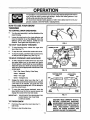
HOW TO USE YOUR SNOW
THROWER
WING KNOB
TO CONTROL SNOW DISCHARGE
Tum the crank assembly to set the direction of the
snow throwing.
e
Loosen the wing knob on the chute deflector and
.... move the deflector to set the distance. Move the
deflector UP for more distance, DOWN for less
distance. Then tighten the wing knob (Fig. 9).
TO STOP YOUR SNOW THROWER
•
To stop throwing snow, release the auger drive
lever (See Fig. 11).
•
To stop the track, release the traction drive lever.
•
To stopthe engine, pushthe throttlecontrol leverto
off and pull out the ignitionkey (See Fig. 10).
:
TO MOVE
FORWARD
AND
BACKWARD
•
To shift, release the traction drive lever and move
the speed shifter lever to the speed you desire.
Ground speed is determined by snow conditions;
= Select the speed you desire by moving the speed
shifterlever intothe appropriatecoloredarea on the
...........
control panel.
=
,-°, ,
'....
=
FIG, 10
,
Red - Wet, Heavy; Slushy, Extra Deep
Amber - Moderate
i
White - Very Light
=
.
•
,
JLWULI
TRACTION DRIVE
LEVER
=
I
I
1_
AUGER DRIVE
LEVER
OFF
Green -Transport only
Engage the traction ddve lever (See Fig 11, left
hand). Asthe snowthrower startsto move, maintain
a firm hold on the handles, and guide the snow
: thrower along the clearing path. Do not attemptto
push the snow thrower;
ON
ON
i
•
. To move the snow thrower backward, move the
speed shifter lever intofirst or second reverse and
engage the traction drive lever (left hand).
IMPORTANT:
.
.
.LEFT
HAND
iii
r
RIGHT
HAND
•
FIG. 11
DO NOTMOVETHESPEED SHIFTER
LEVER WHILE THE TRACTION
LEVER IS DOWN.
CAUTION: READ OWNER'S MANUAL
BEFORE
OPERATING
MACHINE.
NEVER DIRECT DISCHARGE TOWARD
BYSTANDERS. STOP THE ENGINE BEFORE UNCLOGGING
DISCHARGE
CHUTE OR AUGER HOUSING AND
BEFORE LEAVING THE MACHINE,
TO THROW SNOW
•
Push down the auger drive lever (See Fig. 11,
: . right hand).
°
•
_
Release to stop throwing snow.
11
ii
! •
•
, ,,
,-,,
,
i
,
OPERATION
.
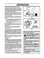
TO USE WEIGHT TRANSFER
i,ii
°
.
i1.11
Hi|
i
=
,
i
HANDLE
'_
Steppingon the weighttransfer pedal shiftsmore weight
to the auger housing. This weight transfer keeps the
snow thrower in contact with the ground and reduces
ride-upon ice and snow.
OFF
ON
in lighter snow conditions or when transporting, you
Should release the weight transfer system for easier
steering.
•
, ,
i
SYSTEM
In hard packed or heavy snow conditions,conventional
snowthrowerstend to rideup and leave uneven mounds
of snowbehind. Forthese conditions, your new tracked
snowthrower has a uniqueweighttransfer system (See
Fig. 12) designedto minimize ride-up.
,
i
FIG.12
To use theweighttransfer,
holdthe upperhandle
firmly
and pushdown on theweighttransfer
pedal
(See Fig.12)withtheball
ofyourfoot.
OIL FILL CAWDIF_STICK
•
To release,
pull
up on theweighttransfer
pedalwith
thetopofyourfoot.
NOTE: The weighttransfer
systemwillnotwork ifthe
auger housingheightadjustskidsareadjustedto the
highest
position.
NOTE: OIL LEVEL
MUST BE BETWEEN
FULL AND ADD MARK
!BEFORE STARTING THE ENGINE
FILL/ADD
OIL:
|
i
RG.13
The engine on this snow thrower was shippedwithout
oil. Add oil before you start the engine. Remove the oil
fill cap/dipstickand fill the crank case to FULL line on
dipstick (about 26 ounces) (See Fig. 13) with S.A.E.
_10W-30motoroil(orequivalent).Do notoverfULTighten
the fillcap/dipsticksecurely each time you checkthe oil
level.
NOTE: S.A.E. 5W-30 motor oil may be used to make
starling easier in areas where temperature is consistently 20 ° F. or lower.
gasolinefrom is clean and free from rustor otherforeign
)articles. Never use gasolinethat may be stale from long
)eriods of storage in the container,
i
A
i i
AND CAUTION MUST BE USED WHEN
CAUTION: GASOLINE IS FLAMMABLE
HANDLING OR STORING IT.
DO NOT RLL FUEL TANK WHILE SNOW
THROWER IS RUNNING,WHEN IT IS HOT, OR
WHEN SNOW THROWER IS IN AN ENCLOSED
AREA.
FILL GAS:
WARNING: Experience indicates that alcohol blended
fuels (calledgasoholorthose using ethanolor methanol)
can attract moisturewhich leads to separation and formarion of acids during storage. Acidic gas can damage
the fuel system of an engine while in storage.
KEEP AWAY FROM OPEN FLAME OR AN ELECTRICAL SPARK AND DO NOT SMOKE WHILE
RLLING THE FUEL TANK.
NEVER FILL THE TANK COMPLETELY. FILL
THE TANKTOWITHIN 1/4 '- 112"FROMTHE TOP
TO PROVIDE SPACE FOR EXPANSION OF FUEL.
To avoid engine problems, the fuel system should be
emptied before storage for 30 days or longer. Start the
engine and letit rununtilthe fuel linesand carburetorare
empty. Use the carburetor bowldrain to empty residual
gasoline from the float chamber (Fig. 42), Use fresh fuel
next season. (See Storage instructionson page 25 for
additionalinformation.)
i ALWAYS FILL FUEL TANK OUTDOORS AND
USE A FUNNEL OR SPOUT TO PREVENT SPILLING.
MAKE SURE TO WIPE UP ANY SPILLED FUEL
BEFORE STARTING THE ENGINE.
Never use engine or carburetorcleane_'productsin the
fuel tank or permanent damage may occur.
!
Filtthe fuel tank with clean, fresh, unleaded grade auto:
STORE GASOLINE IN A CLEAN, APPROVED
CONTAINER AND KEEP THE CAP IN PLACE ON
THE CONTAINER.
:motive gasoline. Be sure that the container you pourthe
t2
H
mnn
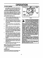
TO STOP ENGINE
•
uw]_wl i i
Be sure that the engine has sufficient oil. The snow,
thrower engine is equippedwith a 120 voltA.C. electdc =
starter and recoil starter. Before starting the engine, be
certain that you have read the following information:
COLD START (See Fig. 14)
•
Move the throttle control up to RUN position.
Remove the keys from the plastic bag. Insert one
key into the ignitionslot=Be sure it Snaps into
place. DO NOT TURN KEY.='Keepthe second key
in a safe place.
•
Rotate the choke knobtO FULL choke position.
•
Connect the power cord to the switch box on the
engine.
nnnunnn|ul
FIG.14
CAUTION: THIS STARTER IS EQUIPPED
WITH ATHREE-WIRE POWER
CORD
AND
,,,,,, ,,, •
i
PLUG AND IS DESIGNED TO OPERATE
ON 120 VOLT AC HOUSEHOLD CURRENT. IT MUST BEPROPERLY GROUNDED AT
ALL TIMES TO AVOID THE POSSIBILITY OF ELEC=
TRICALSHOCK, WHICH MAY BE INJURIOUS TO
OPERATOR.
FOLLOW ALL INST.RUCTIONS
CAREFULLY AS SET FORTH IN THE "TO START
ENGINE" SECTION. DETERMINE THAT YOUR
HOUSE WIRING IS A THREE-WIRE GROUNDED _
SYSTEM. ASK A LICENSED ELECTRICIAN IF YOU
ARE NOT SURE. IF YOUR HOUSE WIRE SYSTEM
IS NOTA THREE-WIRE SYSTEM, DO NOT USE
THIS ELECTRIC STARTER UNDER ANY CONDITIQNS. IF YOUR SYSTEM IS GROUNDED AND A
THREE-HOLE RECEPTACLE IS NOT AVAILABLE
AT THE POIN YOUR STARTER WILL NORMALLY
BE USED, ONE SHOULD BE INSTALLED BY A
LICENSED ELECTRICIAN,
Plug the other end of the power cord into a
three.h01e, grounded 120 volt A.C. receptacle.
• ._ .P_ressthe primer button in cold weather. Press
two or three times while keeping your finger over
the vent hole on the primer button. Additional
priming may be necessary for the first start if the
temperature is below 15 ° F.
•
•
Push down on the starter button until the engine
starts. Do not crank for more than 10 seconds at
atime. This electricstarter is thermally protected.
If overheated it will stop automatically and can
be restarted only when it has cooled to a safe
temperature (a wait of about 5 to 10 minutes=is
required).
WHEN CONNECTING 120VOLTAC POWER CORD,
ALWAYS CONNECT THE CORD TO THE SWITCH
BOX ON THE ENGINE FIRST, THEN PLUG THE
OTHEREND INTO THE THREE-HOLE GROUNDED
RECEPTACLF--
When the engine starts, release the starter button
and slowlyrotatethe choke to OFFpositlon. if the
engine falters, rotatethe choke to FULL and then
gradually to OFF.
•
WHEN DISCONNECTING POWER CORD, ALWAYS
UNPLUG THE END IN THE THREE-HOLE
GROUNDED RECEPTACLE FIRST.
Disconnectthe powercordfrom the receptaclefirst
and then from switch box on engine:
i
NOTE: Allow the engine to warm up for a few minutes
because the engine will not develop full power until it
reaches operating temperature.
•
BOX
CHOKE
CONTROL
THROTTLE CONTROL
•
•
IGNITION
KEY
Be sure the auger drive and traction drive levers
are in the disengaged RELEASED position.
•
u,__
STARTER
BUTTON
PRIMER BUTTON
To stop engine, move the throttle control lever to
STOP position and remove key, Keep the key in a
safe place. The enginewill not startwithoutthe key."
TO START ENGINE (Electric Starter)
s
n
Runthe engine at full throttle RUN when throwing
snow.
WARM START
If restartingawarm engineaftera shortshutdown,leave
choke at OFF and do not push the primer button.
13
i
RATION
,i,
i
illl
CHOKE
CONTROL
CAUTION: NEVER RUN ENGINE INVENTILATED
ENGINE
EXDOORS ORIN AREAS.
ENCLOSED,
POORLY
HAUST CONTAINS CARBON MONOXIDE, AN ODORLESS AND DEADLY GAS.
KEEP HANDS, FEET, HAIR AND LOOSE
CLOTHING AWAY FROM ANY MOVING PARTS
ON ENGINE AND SNOW THROWER.
WARNING: TEMPERATURE OF MUFFLER AND
NEARBY AREAS MAY EXCEED 150 ° F. AVOID
THESE AREAS.
DO NOT ALLOW CHILDREN OR YOUNG TEENAGERS TO OPERATE OR BE NEAR SNOW
THROWER WHILE IT IS OPERATING.
A
I
I
I
To stop engine; move the throttle control lever to
STOP position and remove key. Keep the key in a
Safe place. The engine will not start withoutthe key.
TO START ENGINE (Recoil Starter)
Be surethat the engine has sufficientoil. Beforestarting
-the engine, be certain that you have read the following
information:
COLD START (See Fig. 15)
•
THROTTLE
FIG.15
I
rT(
•
RECOIL
STARTER
KEY
Be surethe augerdrive andthe traction ddve levers
are in the disengaged RELEASED position.
Move the throttlecontrolup to RUN position.
Push the key intothe ignitionslot. Be sure it snaps
intoplace. Do notturnkey. Removethe plasticbag
and extra key.
Rotate choke controlto FULL choke position.
Press the primer button in cold weather. Press
two or three times, while keeping your finger over
the vent hole on the primer button. Additional
pdrning may be .necessary for the first start if the
temperature is below 15° F.
Pull the starter handle rapidly, Do not allow the
....handle to snap back, but allow it to rewind slowly
while keeping a firm holdonthe starter handle:
As the engine warms up and begins to operate
evenly, rotate the choke knob slowly to OFF
position.Ifthe enginefalters, returnto FULL choke,
then slowly move to OFF choke position.
NOTE: Allowthe engine to warm up for a few minutes
because the engine will not develop full power until it
reaches operating temperature.
•
Run the engine at or near the top speed when
throwing snow.
WARM
START
Ifrestartingawarm engine after a shortshutdown,rotate
choke toOFF insteadofFULL and donot pushthe primer
button.
FROZEN RECOIL STARTER
if the starter is frozen and will not turn engine:
•
Pull as much rope out of the Starteras possible.
•
Release the starter handle and let it snap back
• against the starter.
If the engine still fails to start, repeat. If continued
attempts do not free starter, foliQw the electric
starter procedures to start.
To help prevent possiblefreeze-up of recoilstarter and
engine controls, proceed as follows after each snow
removal job.
• _ Withthe engine running, pullthe starterropehard
with acontinuouslull armstrokethree or fourtimes.
Pullingof starter rope will producea loudclattering
sound. This is not harmfulto the engine or starter.
•
With the engine not running, wipe all snow and
moisture_rom the carburetorcoverin area ofcontrol
levers; Also move throttle control, choke control,
and starter handle several times.
ii
i
•
N
ill LJ
i
Illll
•
I
i
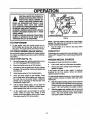
SNOW THROWING:TIPS
e=
, ........
kllr
Formaximum Snowthrowerefficiency,adjustground
speed, notthrottle. Ifthe track slips, reduceforward
speed. The engine is designed todelivermaximum
performanceat fullthrottle and shouldbe run at this
power setting at all times;
,= _ CAUTION: DO NOT ATTEMPT TO RE-,
MOVE ANY ITEM THAT MAY BECOME
_
LODGED IN AUGER WITHOUT TAKING
_
THE, FOLLOWING PRECAUTIONS:
"
• RELEASE rAUGER DRIVE AND TRACTION
DRIVE LEVERS.
....
_ '
_
•
Most efficientsnow blowing isaccomplished when
the snow is removed immediately after it falls.
• MOVE THROTTLE
"nON.
•
Forcomplete snow removal, slightlyoverlap each
path previouslytaken.
• REMOVE (DO NOT TURN) IGNITION KEY.
• DISCONNECTSPARK PLUG WIRE.
The-snow shouldbe discharged down wind whenever possible.
• DO NOT PLACE YOUR HANDS IN THE
AUGER OR DISCHARGE CHUTE USEA
•
F°r n°rmal usage, set the skids sothat the scraper
bar is 118"above the skids. For extremely hardpacked snow sudaces, adjustthe skids upward so
that the scraper bartouches the ground.
•
On gravel or crushed rocksurfaces,set the skids at
1-1/4" below the scraper bar(see To Adjust Skids
Height paragraph Onpage18). Rocks and gravel
must not be pickedupand thrown bythe machine.
•
if the front of the snow thrower has a tendency to
raise, reduce the ground speed and engage the
weight transfer system.
•
Alter the snow blowing job has been completed,
allowthe engine to idlefor a few minutes, whichwill
melt snow and accumulated ice off the engine.
• .... Clean the snowthrower thoroughlyaftereach use.
•
Jl
Remove ice and snow accumulation and all debris
from the entire snowthrower, and flushwith water
(if possible)to remove all salt or otherchemicals.
Wipe snow thrower dry:
15
LEVER TO STOP POSI:
"_
•
_
_
MAI
E
GENE RAL RECOMMENDATIONS
.....
OIL (CHAINS AND SPROCKETS)
The warrantyon this snow thrower does not cover items
that have been subjected to operator abuse or negligence. To receive full value from the warranty, operator
mustmaintain snowthrower as instructedin this manual
•
•
!
Some adjustmentswin need to be made periodicallyto
properly maintain your snow thrower.
Alladjustmentsinthe Service and Adjustmentssectionof
this manual shouldbe checked atleast once each season.
AFTER
•
e
FIRST
USE
:
i
:- -
i
FIG. 16
Check the tracksfortension and adjust_if_tieCessary
(See To Adjust Track paragraph on page 23).
Check thetrack adjustment andfaste ners regularly.
WBGHT
TRANSFER
Be sure that all fasteners are tight.
AS REQUIRED
WBGHT
TRANSFER
PLATE
The following adjustments should be performed more
than once each season.
e
•
Auger and Track Drive Belts shouldbe adjustedafter
the first 2 to 4 hours of use and again about midseason and twice each season thereafter. See To
Adjust Belts paragraph on page 19.
i
FIG. 17
Allscrewsand nuts shouldbe checked oftento make
sure they are tight, preferably after each use.
iUl
i
SNOW THROWER
LUBRICATION
- EVERY TEN HOURS
•
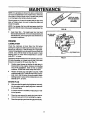
Chain and Sprockets- Oil chainsand sprockets(See
Fig. 16) with10W-30 oil (or equivalent)after 10 hours
use and at the end of each season.
•
Weight Transfer System- Coat weighttransferplate
(See Fig. 17) with clinging type grease, such as
lubriplate,every ten (10) hours and before storage.
•
Auger Shaft- Usinga handgrease gun, lubdcatethe
auger shaft zerk fittings(See A, Fig. 18) every ten
(10) operating hours. Each time a shear bolt is
replaced (see To Replace Auger Shear Bolt paregraphon page 23), theaugershaft MUST be greased.
•
For storage or when replacing shear bolts, remove
shear bolts and lubricate auger shaft zerks. Rotate
augers several times on the shaft and reinstallthe
shear bolts.
LUBRICATION
•
GEARS
WHEEL
- NOT REQUIRED
HEX
Hex Shaft and Gears -Hex shaft and gears require
no lubrication.All bearingsand bushingsare lifetime
lubricatedand requireno maintenance(See Fig. 19).
t
FIG. 19
16
DRNE
PLATE
MAINTENANCE
J ,
i
ii
LI
Illlll
j
ili
ii
i
NOTE: Any greasing or oiling'ofthe above components
can cause contaminationof the friction wheel. If the disc
drive plate or friction wheel come in contactwith grease
or oil, damage to the friction wheel will result.
Should grease or oil come in contact with the disc drive
plate or frictior_wheeJ, be sure-to clean the plate and
wheel thoroughly,
NOTE: For storage, the hex shaft and gears should be
wiped with 10W-30 motoroil to prevent rusting(See Fig.
19).
FIG. 20
Auger Gear Box - The auger gear box has been
factorylubricatedforlife, lfforsome reasonlubricant
shouldleak out, have augergear case checked by a
competent repairhran.
OIL FILL CAP/
DIPSTICK
ENGINE
LUBRICATION
Check the crankcase oil level (See Fig. 20) before
startingthe engine and after each five (5) hoursof continuoususe. AddS.A.E. 10W-30 motoroil or equivalent.
"Fightenfil! cap/dipsticksecurelyeach timeyou checkthe
oil level. S.A.E. 5W-30. motor oil may be used to make
stading easier in areas where temperature is consistently 20° F. or lower.
DRAIN PLU G
i
FIG.21
Change the oilafterfirsttwo hoursofoperation and every
25 hours thereafter or at least once a year if the snow
thrower is not used for 25 hours (See Fig. 21).
•
Positionsnow thrower so that the oil drain plug is
lowestpoint on the engine. Remove oil drain plug
and oil fill capldipstick. Drain 0il into a suitable
container. Oil will drain morefreely when warm.
•
Replace oil drain plug and tighten securely. Refill
crankcasewith S.A.E. 10W-30 motoroil (or equiva.......lent).S.A.E. 5W-30 motor oil may be used to make
startingeasier in areas where temperature isconsistently20 ° F. or lower.
• •
SPARK PLUG
•
Make sure that the spark plugistightened securely
intothe engine and the spark plug wire is attached
to the spark plug.
•
If a torquewrench is available, torque plug to 18 to
23 foot pounds.
_ Clean the area around the spark plug base before
removalto prevent dirt from entering the engine.
•
Cleanthe spark piugand resetthe gap periodically.
17
....SERVICE AND ADJUSTMEN
CAUTION: ALWAYS DISCONNECT THE
SPARK PLUG WIRE AND TIE BACK
AWAY FROM THE PLUG BEFORE MAKING ANY ADJUSTMENTS OR REPNRS.
SKID MOUNTING NUTS
TO ADJUST SKID HEIGHT
_This snow thrower is equipped with two height adjustment skids,locatedon the outside of the auger housing
(See Fig. 22). These skids elevate the frontof the snow
thrower.
HBGHT ADJUST SKID
AUGER HOUSING
For normal hard sudaces, adjust the skids as follows:
_e
i
Make sure the weight transfer system lever is
released by liftingup on the handle.
•
Place extra shear bolts supplied (found in parts
bag) undereach end ofthe scraper bar near but not
under the skid.
•
_
Loosen the skid mounting nuts (See Fig. 22) and
push the skid down until it touches the ground.
Retightenthe mountingnuts.
i e:
Set the skid on the other side at same height.
FIG. 22
•
TO ADJUST CHUTE
CRANK ASSEMBLY
if you cannot rotate the chutecrank fullyto the left and to
the right,you need tO adjustthe chute crank (See Fig.
23).
For rockyor unevensurfaces,raise the frontof the snow
-thrower by movingthe skids down further. This will help
preventrocksand otherdebrisfrom being picked up and
thrown by the auger.
NOTE: Ifthe skidsare atthe maximum height,theweight
transfer systemwill not work.
•
Loosen both 1/2" nuts onthe crank adjusting rod
(using 3'4" wrenches).
•
Rotate the adjusting rod in or out to allow about
1/8" clearance between the notchinthe flange and
the outer diameter of the worm.
•
Once this clearar_e is set, tightenthe nuts.
TO ADJUST SCRAPER BAR
After considerableuse, the metal scraper bar will have
a definite wear pattern. The scraper bar in conjunction
with the skids shouldalways be adjusted to allow 1/8"
between the scraperbar and the sidewalk or area to be
cleaned.
•
After extended operation, the scraper bar may be
reversed. Ifthe scraperbar must be replaced due to
wear, remove the carriage belts and nutsand install
a new scraper bar.
NOTE: Be sure the crank does not touchthe side of the
engine or the cover will be scratched.
i ii
Positionthe snow thrower on a level sudace.
PLASTIC
CAP COTTER
Loosen the carriage bolts and nuts secudng the
scraperbar to the auger housing.
"_'_-
NOTCHED SECTION
INCH
Adjust the scraperbar to the proper position.
Tightenthe carriageboltsand nuts, makingsurethat
the scraperbar is parallel with the working surface.
i
i
.H.
i II Ill
:LATWASHER
CAUTION: BE CERTAIN TO MAINTAIN
PROPER GROUND CLEARANCE FOR
YOUR PARTICULAR
AREA TO BE
CLEARED.
OBJECTS
SUCH AS
GRAVEL, ROCKS OR OTHER DEBRIS,
IF STRUCK BY THE IMPELLER, MAY BE
THROWN WiTH SUFFICIENT FORCE TO
CAUSE PERSONAL INJURY, PROPERTY
DAMAGE OR DAMAGE TO THE SNOW
THROWER.
i
|11 i
ira,iNCH
FIG. 23
L
_18
SE
i
ii
.
= m
AND ADJUSTM
i
ill
i
]
TO ADJUST THE CLUTCH CONTROL
CABLES
i
|
i
ii i
i
CONTROL LEVER
MUSTBE IN FULL
FORWARD POSITION (Just Contact.
lng Plastic Bumper)
WHEN CHECKING
TRACTION DRIVE
LEVER
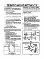
Periodicadjustmentof the cables may be required due to
normal stretchand wearon the belts.To checkfor correct
adjustment, the control lever must be in the lull forward
position,restingonthe plasticbumper.Thecontrolcables
are correctly adjusted when the center of the "Z"Fittingis
in the center of the hole and there is no droop inthe cable
(See Fig. 24).
i
i,,
,Z" FffTING
ff adjustment is necessary:
PLASTIC BUMPER
e _ Disconnec_the _Z" Fittingfrom drive lever.
•
_ _Push the cable through the spring (See Fig. 25) to
expose the threaded portion of the cable.
Hold the square end of the threaded portion with
......pliers and adjust the Iocknut inorout untilthe excess
•
slack is removed.
0
AUGER
DRIVE
SPRING
f
Pull the cable back through the spring and connect
the cable.
Do the same for the other lever cable.
NOTE: Whenever the traction drive or auger beltsare
adjusted or replaced, the cables will need to be adjusted.
TO ADJUST BELTS
FIG. 25
Belts stretch during normal use. If you need to adjust
the belts due to wear or stretch, proceed as follows:
= H
Q_
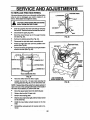
TRACK DRIVE BELT (SeeFig. 27)
The track drive belt has constant spring pressure and
does not require adjustment. Check the clutch control
cable adjustment before replacingthe belt.
IDLER PULLEY-.-._
Replace the track drive belt if it is still slipping (see To
Replace Belts paragraph on page 20).
•
ENGAGED
)
_
AUGER DRIVE BELT (See Fig. 27)
'
F
_
if your snowthrower will not dischargesnow, checkthe
controlcable adjustment. If it is correct, then check the
condition of the auger drive belt. It may be loose or
damaged, if it is damaged, replace it. See To Replace
Belts paragraph on page 20. if the auger drive belt is
loose, adjust as follows:
"•0
DRIVE PULLEY
I),
1/2 INCH
.__,_L.,qw,DEFLECTION
PULL_
FIG. 26
=l= i i
=l
i
TRACK DRIVE BELT
TRACK DRIVE
PULLEY
Disconnectthe spark plug wire.
BELT GUIDE
Remove the belt cover.
AUGER DRIVE
AUGER DRWE
PULLEY
Loosenthe nut on the idler pulley (See Fig. 26) and
movethe pulley toward the belt about 1/8".
Tighten the nut.
TRACK DRIVE
IDLER PULLEY
PULLEY
Presstheaugerddve lever. Checkthetension onthe
belt (opposite idler pulley). The belt should deflect
about 1/2" with moderate pressure (See Fig. 26).
NOTE: You may have to movethe idlerpulley more than
once to obtain the correct tension.
•
IMPELLER
lit
FIG. 27
Replace the belt cover.
Check the clutchcontrol cable adjustment.
Reconnect the spark plug wire.
19
IL
AND ADJUSTMEN I'S
ii
TO REPLACE BELTS
The drive belts on this snow thrower are ol specialconstructionand shouldbe replacedwith originalequipment
belts available from your nearest SEARS Store or Service Center.
m
ii .
L
BELTCOVER
You will need the assistance of a second person while
replacingthe belts.
Drainthe gasolinefrom thefuel tank by removingthe fuel
line. Drain the gas and reinstallfuel line.
114X 112INCH SELF
TAPPINGSCREW
,
r,
=,
, J
"
• •
FIG. 28
AUGER DRIVE BELT
If your snow thrower will not discharge snow, andthe
auger drive belt isdamaged, replace it as follows:
•
Disconnectthe spark plug wire.
•
•
Remove the belt cover (See Fig. 28)
Loosen the belt guides (See Fig.30) and pull
away from the drive pulley.
Loosen the auger idler pulley (See Fig. 30) and
slipthe belt out.
•
•
•
•
Release the auger drive lever.
•
Place the drive belt ontothe auger drive pulley.
•
Adjustthe drive belt (see To Adjust Auger Drive
Belt paragraph on page 19).
Adjust the belt guides (see To Adjust The Belt
Guides paragraph on page 21).
Reinstallthe belt cover.
•
•
TRACTION DRIVE BELT
TRACK DRIVE
PULLEY
GUIDE
IMPELLER
DRIVE
(Le_tHend)
BELT _
AUGER DRIVE
PULLEY
Engage the auger drive lever. This will pull the
brake assembly (See Fig. 29) away from the
pulley and allow the belt to be slippedouL
Remove the belt from the auger drive engine
pulley.
Installthe originalequipment replacement belt in
reverse order of removal.
e
J
TRACK DRIVE
IDLER PULLEY
PULLEY
i
=f ii
FIG. 29
BELT
PULLEY ENGAGED
..,.JMPELLER
•
Check clutch control cable adjustment (see page
19).
•
Reconnect the spark plug wire.
I
PULLEY
FIG. 30
L 20
•
•
i
i
[
•
..........
SERVICE AN
III
i
.......................
USTMENTS
I
IIIIIIII
TRACK DRIVE BELT "
•
•
II
IIII
IIIII
I
I
I
ill
I
I
I
II
i
if the snow thrower will not move forward, you need to
check the track drive belt, the traction drive cable or the
.:fdctio nwheel. Ifthe frictionwheel isdamaged, itwillneed
to be replaced. See the To Replace FrictionWheetparagraph on page 22. If the frictionwheel isnot worn, _heck
the adjustment, as follows:
.......................
Disconnectthe spark plug wire.
Remove the belt cover.+,
Loosenthe lefthand belt guide (See F_, 29) mounting screw and move the belt guide away from the
belt.
+!+,"
.,
•
I
TO ADJUST THE FRICTION WHEEL
,
if your snow thrower willnc)t move forward, check the
track drive belt for wean If the track drive belt needs to.
be replaced, proceed as fo!!ows:
•
•
I
•
Disconnectthe spark plug wire.
•
Drain the gasoline from the gas tank.
•
Stand snow thrower on the auger housing end.
•
Pullthetrackdriveidler
pulley
(See Fig.29)back
and slip the belt past .the idler pulley........
Remove the belt from the engine pulley.
•
Remove the bottompanel (See Fig. 31).
•
Positionthe shifter lever in first (1) gear.
•
Remove the beli between the two large pulleys.
•
•
Installthe new originalequipment replacement belt
in reverse order of removal.
D
Adjust the left hand belt guide and tighten the
mounting screw (see To Adjust The Belt Guides
paragraph below).
Note the position of the friction wheel on the disc
driveplate. The rightside of the friction wheel should
be3-3/8" fromthe leftouterside ofthediscdrive plate
(See Fig. 32).
•
e
Reinstallthe belt coven
o
Reconnect the spark
plug
wire.
.
+
:
If adjustment is necessary:
• Loosen the jam nut"A" on the speed select rod. Re.........
move the balljointfrom the shifterbracket. Lengthen
or shortenthe rodby fumingthe adaptor toobtain the
correctfrictionwheel position (See Fig. 33)
TO ADJUST THE BELT GUIDES
There aretwo belt guides0n yoursnowthrower,a left and
right.After you replace a track or auger drive belt, you
needto adjustone or bothof the belt guides. Proceedas
follows for each belt:
•
Disconnectthe spark plug wire.
•
Remove the belt cover (See Fig. 28)
•
Engage the auger drive clutchlever.
•
Measure the distance between the belt guides and
the belt (See Fig. 30). The distance shouldbe 3/32"
for each guide.
•
•
if adjustment is necessary, loosen the. belt guide
mountingbolts. Move the belt guides to the correct
position,Tighten the mounting bolts
Reinstallthe belt cover.
•
Reconnect the spark plug wire.
iiiii
I
!
I
l
i
+:
•
Reinstallthe ball joint and tighten the jam nut.
•
Reinstallthe bottom panel.
.
I
FIG. 32
.......
....
iiiii i ii i
i
i i
i
SPEED SELECT ROD
•JAM NUT
BRACKET
REMOVE BOLT
LOOSEN BOLT.
P
iiiiiiii+
TRACK CONNECTING ROD
ii
i
U
FIG. 31
I_L
I
FIG. 33
21
.
SERVICE AND AD
i
n
TO REPLACE FRICTION WHEEL
n
i i
FRICTION WHEEL
Ifthe snowthrowerwill not moveforward, and the fdcUon
wheel is worn or damaged, you need to replace it, as
follows:(First allow the engine to cool).
•
Drain the gasoline from the fuel tank by removing
thefuelline. Drain the fuel and reinstailthefuel line.
•
Disconnect the spark plug wire.
•
Stand the snow thrower up on the auger housing
end (See Fig. 36).
LOCKWASHER'
•
=_
Remove the bottom panel (See Fig. 34).
•
: Disconnectthe right side track connecting rod.
•
Rotate the rightside track until it is parallelto the
ground(See Fig 36).
•
HUB
BOLT
FIG. 35
m l
i
i
WHEEL
HEX SHAFT
Remove the three (3) fasteners securingthe friction
=wheelto the hub (See Fig. 35).
_EMOVE
ING
PLATE
AUGER
BOTTOM PANEL
LOOSENBOLT,
TRACKCONHEC'flNG
ROD
FIG. 34
•
Move the shifter lever intofirst (1)gear.
.
Loosen the four No. 10 keps nuts securirngthe
beadngplate (See Fig.36). Do not rernovethe nUts.
NOTE: Reassemblywillbe easier ifyou place a piece of
tape over each ofthe carriage 10oifheads on the insideof
the motormount before you remove the nuts. _;_ :
•
•
*
Move the speed select lever into sixth (6) gear.
" Remove the four No.10 keps nuts,
Rerr_ve the beadng plate.
•
Slidethe hex shafttothe rightuntilthefrictionwheel
•
!nstallthe new frictionwheel loosely on the hex
shall ,
•
Reinstallthe removed parts in reverse order of removal
ca"
removed.
................... 22
ii
i
i
iiii
ii ii
Hill
II1-1
j
i
ii
•
tl
i
S
i
t
ii
iii
i
i
AN
t,
,
i
t
I
I
I
III
I
II
r
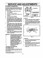
TO REPLACE AUGER SHEAR BOLT
The augers are secured to the auger shaft with special
bolts(See F_.37)that are designed to break (to protect
the machine) if an object becomes lodged in _ auger
housing. Use of a harder boltwill destroythe protection
provided by the shear bolt.
IMPORTANT:
SHEAR
BOLT--_
"
: l
TO INSURE SAFETY AND
PERFORMANCE LEVELS, ONLY
ORIGINAL EQUIPMENT SHEAR
BOLTS SHOULD BE USED. WHEN
REPLACING SHEAR BOLTS, BE SURE
TO REPLACE SHEAR BOLT
SPACERS.
_UT
RG. 37.
To replace a broken shear bolt, proceed as follows:
•
=Move the throttleto STOP and rum off all controls.
•
D'_nnect the spark plug wire. Be sure all moving
parts have stopped.
•
Lubricatethe auger shaftzerk fitting(see the Maintenance section, pages 16-17).
•
Alignthe hole inthe augerwith the hole inthe auger
shaft. Install the new shear bolt and shear bolt
spacer provided.
•
Reconnect the spark plug wire.
.
i
i
k
TRACK
DISTANCE SHOULD NOT BE
GREATBFi THAN 2 INCHES
SIDE PLATE
O
TO ADJUST TRACK
E,
(A) _:_CAM
_WASHER
-,:•
ifthe snowthrowerdoes not moveforwardeve nlyand the
trackslipss6gh_y_,
you needto checkthe trackas foliows:
•
Measumthe dislance between the top of the side
plate and the inside of the track. The d'Blance
should not be morn than two (2) inches.
RG. 38
tithe distance Is greater, you need to adjustthe track as
follows:
_.
•• ......Lcosenthebolts (A) (See F_I. 38) onbomsidesof
thetrackassernU_•
Turn the cam washers equally on both sides.
*
_just thetracktoreduce
s_c_.somam_e
¢mnce
=: ,,..
the track is notgreater than two (2) inches. Be sure
the cam washers are adjusted evenly or the track
wmbe :_
(See RO. 3S).:Uthe Uackbecomes
_nL
LJ'T'F.,q-'T-q'-I_
.............
tt,,tttttt,,,
i
:;i
II
I
i
TO ADJUST CARBURETOR
....
The carburetor(See Fig.40 and Rg. 42) hasbeen pre-set
_t the factoryand readjustmentshould notbe necessary.
_lowever, if the carburetor does need to be adjusted,
proceed as follows:
•
•
q,
Close the high speed adjusting screw by hand.
Do not overtighten.
._
Then open it 1-114to 1-1t2 turns.
•
!
Close the idle adjusting screw by hand. Do not
overtighten.
q
Then open it 1-1!4 to 1-1/2 turns.
_'
•
.Start:theengineandletitwarmup.
•
Set the throttle=control to RUN. Adjust the high
speed =adjustingscrew in untilthe engine speed or
_i ' sound alters. Adjustthe screw out untilthe engine
speed sound alters. Note the difference between
•_ the two limitsand set the screw in the middleof the
TO ADJUST:
•
.....
Clean :the spark plug by carefully scraping electrodes (do not sand blast or use awi m brush).
•
Be sure the spark plug is clean and free of foreign
material.Check electrodesgap (See Fig. 41) with a
wire feeler gauge and resetthe gap tO .030 inch if
necessary.
_::. range.
e
.Setthe_thmttle control to SLOW. Adjust the idle
adjusting .screw in until the .engine speed drops,
. , :.then adjust the screw out until the engine speed
:drops, Note the difference between the two limits
_-! andset the screw in the middle of the range,
L
•
RG. 40
.......
'
e-
If the,engine tends to stall under load or not accel" erate from low speed to high speed properly,adjust
the highspeed screwout in 118turnincrementsuntil
:. :the problem is resolved.
€
Let-the engine run undisturbed for 30 seconds
between each settingto allow the engineto react to
the previousadjustments.
I DIPORTANT: NEVER TAMPER WITH THE ENGINE
' :: "
GOVERNOR, WHICH IS FACTORY
SET FOR PROPER ENGINE SPEED.
OVERSP.EEDING THE ENGINE
?
L ABOVE THE FACTORY HIGH SPEED
"_
.L SETTING CAN BE DANGEROUS.
IF=YOU THINK THE ENGINE "
GOVERNED HIGH SPEED NEEDS
L
..
ADJUSTING, CONTACT YOUR
NEAREST SEARS SERVICE CENTER,
L WHICH HAS THE PROPER
.... EQUIPMENT AND EXPERIENCE TO
MAKE ANY NECESSARY
ADJUSTMENTS.
TO ADJUST OR REPLACE
THE SPARK PLUG
Ifyou have difficultystartingyoursnowthrower,you may
need to adjust or replace the spark plug. Follow the
instructionsbelow.
Replace the spark plug ifelectrodes are pittedor burned
or it the porcelain is cracked,
,11,,,,
ii
i
FIG. 41
TO REPLACE:
If you need a new spark p!ug, Useonly the proper
replacementspark plug (See page 4.), .
•
Set the gap to .030.
:-::
:_
•'
Beforein_taliing the spark plus, coat.its threads
lightlyw_h graphitegrease to insureeasy removal.
•
Tighten the plug firmly into the engine.
•
If atorque wrench is available,torque the plugto 18
to 23 ft - Ibs.
o
=.
[ii
,
iiii
ii
i,,,,,ii ,,,,, ii
i i
Hll
l
m
I Ill
I Iill
I
:
_;
IIIIIIIIIIIIIILI
i iji
CAUTION: NEVER STORE YOUR SNOW
THROWER INDOORS OR IN AN ENCLOSED, POORLY VENTILATED AREA
IF GASOLINE REMAINS IN THE TANK. FUMES
MAY REACH AN OPEN FLAME, SPARK OR PILOT LIGHT FROM A FURNACE, WATER HEATER,
CLOTHES DRYER, ClGARETi'E, Ei'C.
DRAIN
BOWL
To prevent engine damage (if snow thrower is not used
for more than 30 days) follow the steps below.
RG. 42
ENGINE STORAGE
Gasollnemust be removed or treated to prevent gum
deposits from forming in the tank, filter, hose, and
carburetor during storage. Also during storage, alcohol blended gasoline that uses ethanol or methanol (sometimes called gasohol) attracts water. It acts
on the gasoline to form acids which damage the
engine.
•
•
SNOW THROWER
To remove gasoline, runthe engine untilthe tank is
empty and the engine stops.Then drain remaining
gasoline from carburetor by pressing upward on
bowldrain locatedon the bottomofcarburetor (See
Figure 42).
If you do not want to remove gasoline, a fuel
stabilizer (such as Craftsman Fuel Stabilizer No.
33500) may be added to anygasolineleft inthe tank
to minimizegum deposits and ackls. If the tank is
almost empty, mix stablilizer with fresh gasoline in
a separate container and add some to the tank.
ALWAYS FOLLOW INSTRUCTIONS ON STABILIZER CONTAINER. THEN RUN ENGINE AT
LEAST 10 MINUTES AFTER STABILIZER IS
ADDED TO ALLOW MIXTURE TO REACH CARBURETOR, STORE SNOW'i'HROWER IN A SAFE
PLACE. SEE WARNING ABOVE,
STORAGE
•
Thoroughlyclean the snow thrower.
•
Lubricate all lubrication points (see the Maintenance section on pages 16-17).
•
Be sure that all nuts, belts and screws are securely
fastened. Inspectall visible moving parts for damage, breakage and wear; Replace if necessary.
•
Touch up all rusted or chippedpaint surfaces;sand
lightly before painting.
•
Cover the bare metal pads of the blower housing
auger and the impellerwith rust preventative, such
as sprayable lubricant.
NOTE: A yearly checkup or tuneup by a SEARS Service
Center isa good way to insurethat yoursnow throwerwill
provide=_imum performancefor tha next season.
O'I_IER
You can keep your engine in good operaUng condition during storage by:
•
Changing oil.
•
Lubricating the piston/cylinder area. This can be
done by first removingthe spark plug and squirting
clean engine oilintothe spark plughole. Then cover ....
the spark plug hole with a rag to absorb oil spray. •
Next, rotate the engine by pullingthe startertwo or
three times. Finally,reinstallspark plug and attach
spark plug wire.
=
25
•
if possible, store your snow thrower indoors and
cover it to give protection from dust and dirt.
•
Ifthe machinemustbe storedoutdoors,blockupthe
snowthrowerto be sure the entire machineisoffthe
ground.
•
Cover the snow thrower with a suitable protective
cover that does not retain moisture. Do not use
plastic.
IMPORTANT:
NEVER COVER SNOW THROWER
WHILE ENGINE AND EXHAUST "
AREAS ARE STILL WARM.
SERVICE RECOMMENDATIONS
,,,,
,i
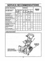
SERVICE RECORDS
.....:_
]
Fill in dates as you com.
:
SCHEDULE
i
'
_=:SERVICE
i
:r After
Before Often
_':-First 2 Each "
Every Every
:i
10 : .
hoursl Use......
25
Each
Before ......
_
,
L
Hours Hours Season Storage ....
CheckEng ne0_1Level
Change Engine Oil
Tighte a All Screws and Nuts
.......
_.,
•
GheckTract_n Clutch Gable
,.
L
"|
,
.,
•
Adjustment (See Cable Adjustment)
A_u=Dr_veBeBts:
Replacement)
:.,
,
"
.
Lubricate Sprockets and Chains.
V" ' __ "'"
.
.
"
11-
,:
,i,
•
'
.
Drain Fuel
......
'
Check Auger Clutch Cable
•
: l
Adjustment'(See Cable Adjustment) ,'
.... •
'_:- :•:
.
,
.
,
'
, ,:....
v'
'
,
I
ti
•
_,
11
,
=
;....
LUBRICATION CHART:
011chains and
sprockets with
10W-30 oll
Lubricate auger shaft.
Coat with a clinging type
grease such as Lubriplate.
26
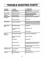
TROUBI, E SHOOTING POINTS
,
iiii
i
TROUBLE
i
i
ii
II
IIII
mill
I
CORRECTION
CAUSE
I
Diffieuit starting
i
iii
IIIII
Replace defective plug.
Use carburetor bowl drain to flush and refillwith fresh
Defective
spark0ug
Water or _rt in fuel system
fuel.
ill
Engine runs erratic..
i_
ii
H lIJ_
i
IJ
I
Clean fuelline; check fuel supply;add flesh
Blocked fuel Sneer low on fuel
fuet;(gaseline/oil mixture if 2 cycleengine) ....
UNpesi£;;
Engine stalls
Unitrunningon CHOKE
Set choke lever to
Engine runs el'ratio;
Water or dirt in fuel system
Use carburetor bow]drain to flush and refill with fresh
fuel.
Loss of power
,,,,
Cmbumtor out of adjustmont
Adjust cerbumtor.
Loose parts; damaged impeller
Stop eng!,ne immed'_ly and diso=nnect spark plug wire.
Tighten all bolts and make ell necesse_ mpairs:ff vibration
i
• ,,i ,
Excessive vibration
con_nues, have the u nitserviced by a competent repairman
Unit fails to propel
Itself
Ddve belt loose or damaged
Replace c_ivebelt
inoormct adjustment of It-action
drive cable
Adjust Iraction ddve cable.
Worn or damaged frk:tlonwheel
Replace friction wheel.
]
Unit falls to
HIe
Ir I I|lll
HI
m
rl
Adjust
augerdrivebe_;replase
ifdamaged.
Auger drive belt loose or damaged
discharge snow
Auger control cable not adjusted
Adjust auger oontrol cable
corre_
Shear bolt broken
Replace shear bolt..
Stop engine immediately and disconnect spark plug wire.
Discharge chute dogged
....
Foreignobjestlodgedin auger
Clean dischatgechute and inside of auger housing.
Stop engine immediately and disconnect spark ldug wire
Removeobject
Headlight
does not work
Loose wire o_nnec_on
Tighten connection.
Bulbburned out
HHI
Unit rides up
from auger.
Replace headlight bulb.
I
Engage weight transfer pedal.
Weight transfer disengaged
• %
27
CRA_SMAN
26" TRAC-PLUS SNOW THROWER 536.885910
Assembly RepaW PartS i :_::
:!,
i
::
:
:
:::: =_I_:,:_
39
....
71
: _= "1
7
......
731 ¸
77
61
k
.66
....
, 16,
_
72
:
,17
t8
37
':
L
• •
17
22
72
:
48
38
50
49
m
" i¸
_
_,_:
_
1,,
....... 17_
51
,
17
_-
45
17
H
16
_:_i_
24
.............
26
18
28
43
47 46
4647
CRAFTSMAN 26', TRAC-PLUS SNOW THROWER 536.885910
RE[=. PART NO.
NO.
1
2
3
4
5
6
7
8
3535
309344
3538
4049 ::.
308012
70990
_308793
• 308037
53681
71059
71034.
PART NAME
RER
,:i
" PART: NAME
_ : : :_: :
k
5/16" Cap Nut : _.
Adapter, Bootto Haadle•
Pivot Pin
".
Bumper ' ,/:
Upper Handle .:::i
5/i6-18 x 1-3/4 In. Bolt
ControlPanel Decal, .........
,Sh tLever::.................
ShiftContml K_b
"
10
114"Lockwasher
11
1/4-20 Hex Nut ....
12
Control Panel
306523
'13 i- 310421
Support Control Panel Ass'y
14'
308901 "Taptite Screw, 10-24 x 5t8 In.
15
310391
1/4-20 x 2 In. Carriage Bolt
5/16-24 Hex Nut
16
71042
5/16" LodoNasher
17
71060
18
50782
Ball Joint
19
6352
Adapter, Speed Control Rod
20
50786
Spring
21
71072
13/32 In. Flatwasher
71038
5/16-18 Locknut :"'
22
23
1668
Speed Control Rod • : .....
24
1449
Lever, Speed Control '
•
25
73801
5/32-7/8 Roll Pin
26
73812 .......
!/21n. Ratwasher .
27
1579 :Clutch Cable
28: I
7288
i_3/8:,16x 3 In__Bolt
:ii:71062 ;: 3/8 irl. Lockwasher
_29
30
:71044 : 3/8-16 Hex Nut
31 _
7289
Plastic Stop
32
71046 : 3!8-16 NylonLocknut _ •
33
71'497 EyeBolt
::i:i
34
70984
5/16-18 x 3/4 In;Screw,
.
35
308011 _ Lower Handle
....
:
36
1672 _ Drive ClutchSpring ........
..:i:,.
37
1673 i _Augei_ClutchSpdng
38
71035
1/4-20 Locknut
......
:.:
39
304872
Retainer Ring
....
.::;
307399
Chute Crank Handle. :, ....... :_'
40
.
PART NO.
NO.
41
42
43
44
45
46
85192
Chute Crank
148
Eye Bolt Grommet
71082
3t32 x 1 In. Cotter Pin
.:104::i Plastic Cap
Chute Control Rod
. 7055
1/2-20 Jam Nut
7058
1/2
In. Lockwasher
_":i :."7059
48
70993
5/16-18 x 3/4" Carriage Bolt
49
7052
L.H. Chute Rotate.Bracket
R.H. Chute Rotate Bracket
50
1162
5/16-18 Hex Nut
51
71037
52
580527
i 5/16 In. Saddle Washer
3/8-16 x 2 In Screw
53
: • 71007
Gear selector Decal
54
•: 6300"
Traction Drive ControlDecal
55 .... 3902
56 ' .....
390_ .....
,:AugerDdveContml Decal
:
57
307395
Upper Headl!ghtHousing ';
Metaiized Back ..... ::!:
58
309792
59
580530
,.LowerHeadlight,Housing
60
307781
#8x 1-3/4'_Screw '..
' 61
307767
Widng Hamess_Headlight AssemI
?
bly
•_,
162
580532
Headlight Mounting Bracket
63 : ..... 4160". 5/i6,18 x 1-3/4" Carriage Bolt
64
309789.
Headlight, Lens
65
309791.,
Headlight; Bulb
66.
710_
3/8" Jam Nut
67
6636
Split Plastic Conduit
:.68
235
ScrewHex Head 5/16-18 x 2 In.
Head LightAssembly
.69
305025
Flatwasher, 11/32 In.
70, I 71071
Socket
71
309793
72
308148
Clutch Spring Boot
73: ... 308145 _ Eyebolt Boot
74:
307918
Auger Drive Lever, R.H.
-"75
307920
Traction Ddve Lever,L.H.
76
71061 :'! Extemal:Lockwasher
Cable'lie
77
: 57444
" :78:"
309312: _ Flatwasl_er,3/8 In.
•79
307145 _":; Owners Manual
i
• 29
CRAFTSMAN
26" TRAC-PLUS SNOWTHROWER536.885910
9
Motor Mount Assembly ,Repair Parts
49
51
\
53
18
6O
57
3755
4
70
6e
-"/ 6e
67
23
23
6
61
72
87 74
7 73
11
5O
8 29
/31
33
=.
31
13
80
30"
\ 84
81
92
85
39
83
41
42
7
44
26
/
25
45
87
47
46
48
33
88
14
71
15
3O
89
88
CRAFTSMAN
REF.
NO.
PART NO.
26" TRAC'PLUS'SNOW
T ROwER
REF.
NO.
PART NAME
536:885910
PARTNO.
' "" ,,,i,,
47
48
49
50
51
52
53
54
1
2
3
4
5
6
7
8
9
10
308646
Motor Mount Frame
308932
Belt Cover
308010
Craftsman Engine, Model No.
70988
5!16-18 x1-114" Bolt
71060
5/16" Lockwasher
85494
Clutch Cable Lever ,
ti2"Flatwasiier
.......
.
71074
_ .
73801 • 5t32 x 7/8" Roll Pin
53703
Flanged Bearing
85492
Clutch Auger Lever Assembly
11
' .710671 1/4" Flatwasher
12
70978
114-20 x 1/2, Self Tapping Screw
13
70982
5116-18 x 1/2" Self Tapping Screw
14
6215
48 Tooth Gear
15
308009
Bottom Cover
16
50795
3/4" Hypro Key
.! :_i: .i
17
7287
Roller Beadng
' ......
18
6106
Flatwasher
5/16-18 x 3/4" Bolt
_
i._
19
70985
5/16 x 1-3/8 x 14 GA Flatwasher ..
.20
73795
21
53793
Idler Traction Lever
22
53794
Spacer
' ....
5/16-18 Locknut
23
71391
24
5-3704 : Idler Traction Drive Spring
•
3/8-16 Hex jam Nut
25
..... 590
26
71010
3/8-16 x 1-1/2" Bolt
....
'27.
71072
3/8" Flatwasher
Belt Retainer Washer
28
i......73787
LH. Belt Guide
29
3948
30
3949
R.H: Belt Guide
i5t16" Flatwasher
31
71071
5116-24 x 1" Bolt
•32
71393
33
577399
5116,!8 x 112"Set Screw '
34
55025 ' : Engine Pulley
35
20579
!Key, WDRF # 5
Wave Washer
36,
30289
37
6103
Outer Beadng Retainer
38
3947
Engine Pulley Spacer .....
.
39
153715 Auger Drive Pulley
40 ....
50677
Fiatwasher
._'
41
71063 :I 3t8" Lockwasher
3/8-24 x 1, Bolt
42
71015
43
50793
1-7i8:' idler Puiley ,
44 :: _i.....145i ," Shaft & LeversAssembly
45 •
.443
Auger Brake spring,
46
301545. 5, impeller Pulley
56
71111
71461
85504
6105
6107.
.72531
3/8-16 Locknut
#10-24 Keps Nut
Bearing Assembly
Inner Beadng Retainer
Ball Bearing
._
10,24x 3/8" Cardagel Bolt
58
' 538331 j8 Tooth PinionGear
"
53832.1I Hex DiscFdction Wheel Shaft
71086::i1/8x 3!4" Rot!Pin
" ::
73811..:. 1/4" Snap Ring.i
: _
85501 :' .Trunion Bead_
Friction Wheel Hub
Friction:Wheel. :
53830
_11871
1t4-20 x 5!8" Bolt
1/4" Lockwasher
.=71059
114-20 Hex Nut
71034
308005
Pivot Bracket
1/4-20 x 1-3/4" Bolt
71360
114-20 Locknut
71035
5/16"
Spacer
"
51438 '
73839
1/4-20 x 2-1/4" Bolt
85499
Traction Shaft Assembly
53816
1/2" Spacer
1/8 x 1" Cotter Pin
71079
73817
1/2" Push-on Nut
53807
Friction Wheel Disc
7091
Traction Hex Shaft
7286
Thrust Bearing
-53818
Return Spring
53820
Clutch Spring
Clutch Rod
53821
53819,- Traction Spring Bracket
. ' _73823 :, .1t8 x 1-3/8" Spring Pin
73822
1/8 x112" Spring Pin
71081 _ 3132 x3/4" Cotter Pin
1/4-20 x 1-1/4" Bolt
_.70970
i 73826
114-20 Locknut
53836
Shaft Hex Beating
Track Axle Shaft
302025
53829
Flange Bearing
85503
Flange Bearing Plate
73840
Ftatwasher, 3/4"
-60 _.
61
62
:,63 i"
:i
65
66
67
:68
:69
70
71
72
73
74
75
76
77.
78
79
80
81
82
83
84
8586
87
_88
i89::
90
_91
92
31
"
Special Auger Drive Belt
Shift Control Shaft
1/2" Flatwasher
,.59
'
.............
5938
3887
85495
73812
55
i: I
PARTNAME
CRAFTSMAN 26" TRAC-PLUS SNOW THROWER 536.885910
Track Assembly
Repair
Parts
14
14
1
/
21,
32
25
19
2
15
./
17
6
37
15
42
33
29
27
18
19: '
15
16 15
2619
36 37
2O
31
46
23
21
32
CRAFTSMAN
26,' TRAC, PLUS SNOW THRO_ VER 536.885910
REI=. .................................
NO.
PART NO.
PART NAME
=
i
i_
-.:
'
Foot Pedal
LH. Bracket
3
308039_ R.H. Bracket
4. i ! _, 6025 =Tension Spring
1t2" PalNut
6
60Ol 7/16" Shoulder Bolt
7
70978
1/4-20 x 1/2" Self Tapping Screw
8
71060 5/16" Lockwasher
9
71037
5/16-18" Hex Nut
10
71005
3/8-16 x 1" Screw
11
71062
3/8" Lo_washer
12
71045. 3t8-16 Jam Nut
13
70985
5/16-18 x 314"Bolt
14
71391
5/16-18 Locknut
15
301818
Track Drive Wheel....
16
5930
Sprocket
17
5917 Chain
18
5947
1/4-28 x3-3/4" GR5 Screw
19
71067
1/4" Flatwasher _. _.. .... .20
6108 :::114-28
Locknut :::: .....
21
71348
5116--18rx112"Bolt
.
"
5/16" Belleville Washer
22
5951
23
5950
1/2" Flatwasher
1
2
•
308050
_.308038
i
.,_NO. . PART---NO..
.
,:• ........
PARTNAME
4-3/4" Track
Track Wheel Shaft
t/2, Hardened Ratwasher
Track Idler Wheel
3/4" Flatwasher
308883
Inner L.H. Track Plate
308882 :. Inner R.H. Track Plate
.308034 1 Outer L.H. Track Plate
::308036
Outer R.H. Track Plate
301816 InnerTrack Beadr_ Hub
30!8!9 _!Outer Track Beadng Hub
71035 .... 1t4-20 Locknut
.70969 . 1/4-20 x 1" Bolt
::......6403 __:Cam Washer
3041331: Sprocketand Hub Assembly
_:73840
3/4"Flatwasher .....
Shear Bolt
7285
24 :9724
25 ::::, 302024
26
_i_ 7074
.....
27
301817
8
29
30
31
32
33
34
35
36
37
38
39
40
41
,:::7_26 1/4-2ob:)cknm
42 -. :302026:
43
i: 20465:'
46
33 .....
..
Track TieRod:
'
1/8" HairPin
:73839/ 1/4-20 x 2-114"Screw
821,.-s
" 48 Tooth Gear
308787 : Trac Plus Decal
CRAFTSMAN 26" TRAC-PLUS
SNOW THROWER 536.885910
•
Auger Housing Assembly Repair Parts
1
26
31
32
45
25
27
29
17
15
3
18
36
3 15 16
33
33
35
41
38
43
4O
42
34
CRAFTSMAN
RER
NO.
•
•......
26, TRAC-PLUS SNOW THROWER 536.885910
•
.............
PARTNO.
+•• .........
NO.
PARTNAME
PART NO.
23
24
25
, 26 :
27:
28
29
30
i, 31
I 32=
_
r
"r
%
14
308931
307693
302678
_
9
10
11
Striped Danger Decal ....
UpperChut eDeflector
5/16-18HeX :Nut . :
,
Wing Knob
5/16" Flatwasher
L+
5/16--18 LOcknut
5/16-18 X 1-1/4" Carriage Bolt
5t16-18x 3/4" Pan Head Slotted
Bolt
Chute Hinge Wire
Lower Chute
114-20 x 1/2" Pan Head Slotted
.........
308768
307665
71037
57171
302680
71391
302843
302634
=
1
2
3
4
5
6
7
8
_
+,
" 33
"34
• 35
,36
+BOR
12
302635
"1/4-20 Wide Flange Locknut
13
577400
5/16-18 x 3/4."Bolt _
14
53.759 _ 6.5" Auger Pulley
.++
15
71060
5/16" Lockwasher •
+=+i
16 • 171071 _=5/16"Fl_asher
17/
308059
Bearing Retainer
+ +++
ts
308119 R.H; Side Plate
Danger Decal, Read From =Side
19
_• 302922
,,.
+20
20556
3/16" Key _"
+
' "
8-32 X 1/2"++BOlt ....
21
71032
::302275
Chute Rotating Ring "
.+
+
,
'
•
38
39
42
43
44
45
,,
35
PART NAME
.
302172
Lower Chute Ring Clip
71058
#8-32" L.ocknut
70142
Chute Danger Decal
Low Chute Ring
308851
Impeller Decal
7376
308766
,Craftsman Decal
70141
Auger Danger Decal
1160 • Auger Housing
Size Decal
308792
LH.
Side Plate
308! 18
5/16-18
x 3/4" Carriage Bolt
70993
' 70984
5/16-18 x 3/4" Self Tapping Screw
307912+ ,Height Adjust Skid
5/16-18 x 5/8" Bolt
70983
1153
Scraper Bar
1/4-20 x 1-3/4" Bolt
9524
3943 1t/4" Spacer
1" Auger Shaft Bearing
73755
Auger Washer
73826
114-20 L-ocknut
308008
R.H. Auger
308007
LH. Auger
310860
Bracket, Chute Stop
53757
Aft
"
•,
CRAFTSMAN
26" TRAC-PLUSSNOW
TH ROWER 536.885910
GEAR BOX REPAIR PARTS
11
7
12
13
1, 15 16
8
6
17
19
18
20
21
2O
2
REF.
NO.
PART NO.
1
2
3
4
5
6
7
8
9
10
11
12
71393
308006
73905
301561
71100
1065
53737
10905
53735
53734
53733
50795
REF.
NO.
PART NAME
13
14
15
16
17
18
19
20
21
22
23
24
5/16-24 X 1" Bolt
ImpellerShaft Assembly
Woodruff Key #91
Auger Shaft, 26 In.
5/16-24 Flange Locknut
Oil Seal
Quad Ring
Flange Bearing
i7/8" Flatwasher
7t8" Roller Bearing
7/8" Flatwasher
i314"Key
36
PARTNO.
53732
50683
50688
53731
53749
53743
53748
53730
897
896
912
PARTNAME
1-3/4" Worm Gear
3/4" Flatwasher
Retaining Ring
Sleeve Bearing.
LH. Gear Box Housing
1/4 x 18 Pipe Plug
Auger Gearbox Bearing
1" Flatwasher
Worm Gear
Gear Box Gasket
R.H. Gear Box Housing
5/16-24 x 1-1/2" Bolt
CARBURETOR
• _r'_
NO.
632334A
_i+'
_'_+r_ ;_'i
'_ ....
+
I
I
!
I
28
12
l
REWIND STARTER
Part
NO.
ReL.
No,
Part
No.
Part Name
Carburetor
.....
631776A Shaft £t Lever Assy., Throttle
63197O Spring. Throttle return
631778
Shutter, Throttle
650606
Screw, Throttle _ Choke shutter
63O766 Spring, Regulatingscrew
5
63O738 Spdng, Main adjustment screw
650417 + Screw, Idle regulating,--_,
6
632112
Shaft 8- Lever Assy,; Choke
"'8
63O735 Spring, Choke positioning
9
632174 Shutter, Choke
:10 *630748 Plug, Welch
11 "631027 Plug, Welch
12 "631021 Inlet Needle, Seat 8. Clip Aasy,
(ind. No. 13)
' r13
_1022
Clip, Inlet needle
+14- 632019 Roat, Carburetor
,
15 *_I_4
Shaft, Float
,
+
_+16
_I_1
Bowl, Float [Incl. Nos: 17 8-18)
' '17
_136A PlungerAssy, Drain (Incl. No, 18)
27554 Gasket. Drainplunger
_132239 Adjustment Screw Assy., Main
|incl. Nos. 5A, 21, 23 8. 27)
_110
..G_€,et,
Bowl-to_oody
+ '
:+2123 ,6307_
"'O Ring, Adj.u_rne_ntscrew
24
'
632281. Screw, Idle adjustment....
I_25
*_1028
Gasket, Bowl-lx_-body
6321_
F_lJng, Fuel inlet
'
63O7'39 Washer
+ : ,: +,
/
g
632347 Repair Kit (Ind. itemsmarked *)
1
4
NO,
NO. 590630
.12
:10
i
,
Part
'..,_....
Name
ss0_0 + Starte_,Rewi_
I
2
3
4
590599A
580600
590651
580627
Pin, Spring (IncL No. 7)
Washer +
Spring Assy,, Brake 8. Dog
Retainer
5
5_641
590628
5g0451A
590629
WDoga_tarter
Pulley
Rope, Starter
Spring 8- Keeper Assy.
9
10
1211_59083590574
withHandle'starter)Mitten
Grip (Not included
Housing Assy_,iStarter
mt
;
k
CILAFTSMAN
.4-CYCLE
ENGINE
I I IIIII
MODEL
NUMBER:
143_
H III
I
I
ILIIIL
IIII
!
!
|
I
I
78
B1
66
25
24
i
216
MODEL
u4 SI_IAL
NUMBERS
HERE
19A.
t46
I
118
117
210C
139
114
¥
194
162
199
213
160
/
196
38
(RAFTSMAN4"CYCLE
ENGINE
MODELNUMBER:
143.806082
l_'f,
66
35385
650_Z0
34171
30869
: 35319
27652
35326
650561
Paxt Name:
:, 27880A
67
67
68
68A
• 69
7O
Valve, Exfraust (ind, No. 70):(1132"
oversize)
•
34035
Valve; intake {incl. No. 70) (Std,)
34036
_Valve, Intake (Incl. No. 70) (1132"
'
oversize)
.
27882
Cap, Upper valve spdng
34689
Seal Assy., Intake valva
,27881 : Spring, Valve
32581
Cap, Lower valve spring
,Kw, Rywhe¢
,77
_-,
29443
32_9
Clip, :Spring
:
80
81
82
650881
650872
35135
82A
83
610118
95
86
Nut, !:lywhecl • .
.
Stud, Solid.statemounting
:Solid State Assy. ,
'
Cover, , Spa_piug
"
r__S_
TOn( HeX washer hd. crams,
10-24x I
650873 ' :screw, Hexhd. Semso1/4-20x314
611J11: i Coil Assy., Altemator (18 Watt}
r Wire,/Ground
.....
85
•
: : ,
Rywheel(w/ring gearj
Wader, Lock
,=,
.......
•
_,
850727
103 ....
104
105
106
107
108
168
114
115
117
118
!19
650684A
"27896A
28423
28424
28425
3535O
65O128
29752
"33283
33877
30068A
650378
120
121
122
123
124
"279!5A
34687
28820
33377
650767
Washer, Rat
.....
Screw, Special he)( hd, tapped,
5116-18 X 1-3/4
Washi_., Rat
Screw
:: •
Gasket, Breather
Body, Breather
Bement, Breather
Cover, Breather
Tube, Breather
Screw, Hex hd. Sems, 10-24 x 112
Nut 8- L0ckwasher, 114.28
Casket, Carburetor
Pipe, Intake
Screw, RI. hd. Serns, 114-28 x 1
Scrm_, Toix RI. hd. Serns, 5116-18 x
1-t/8
Gasket, Intake
Bracket, Chokepipe
Screw; RI. hd. Seres, 10-32 x 112
Bracket, :Carburetorcover mounting
Screw; Hex washer hd. Seres, taptlte,
8-36 x 518
Housing, Blower
PrimerAssy.
Une, Primer
BracketAssy., Control (Ind. Nos. 134,
135, 135 8 135)
Spdng, Compression
Screw, RI. hd., 5-40 x 7/16
Termfi'nalAs=y,
Screw, Hex washer hd. thread cutting,
10-32 x 112
L
luu
101
_
:
L
_
L
86
"34041A Gasket, Cylinder head
97
3A03O
Head,Cylinder
•
98
.; 6021A _ Screw, Hex flange hal.5116-18 x 1-1/2
89 .......
33636 1 Spark plug (Champion :J._C or
[
_
r
:
•
650814
Cylinder (incl. Nos. 3; 4 8- 5):::
Screw, Hex hd. shoulder, I14-20 x 112
Nipple, Pipe, 5-112.....
.....
Cap, Oil drain
Seal, Oil
Pin, Dowel
....
Baffle, Blower housing
Sinew, Hex washer hd. Dudok, 1/4.20
x 5/R
8
35442B
Crankshaft
9
34_2
-Piston, Pin 8. Ring Am/. (IncL Nos.
9A, 10 8. 11) (Std,)
:::
9
3_3
¸_¸
.F_ton, Pin 8. Ring As=y. (Ind. Nos.
9A, 10 8. 11) (.010 oversize) :_
9
34554
:Piston, Pin 8. Ring Assy. (Ind, Nos.
9A, 10 8. 11) L020 ovmsize)
9A
34329A ,Piston 8. Pin A=_. (incl. No. 10) (Std.)
9A 'r:r ' 34330A' "Piston 8" Pin Assy. (Ind. No. 10) (.010
oversize]
......
9A :: ::_34331A: _.piston8. Pin Assy. (incl. No. 10) (.020
ove_)
•
10
27888
Ring, Piston pin retaining
:
11
Ring Set, Piston (Std.}
....
11
Ring Set, Piston (.010 oversize) _
11
34334
Ring Set, Piston (.020 ovmsizs} 17
RodAuy., Connecting (incl. Nos.18,
19 8" 19A)
18
35374
Dipper, Oil
19
680808
BOlt, Connecting md
,
19,6,
65O882
Bolt, Connecting rod
20
34034
Lifter, Valve
21
Camshaft (Mechanical Compression
Release)
22
35273A
hou=in x 112
23
65o128 sxtansion,
Screw, HexBlower
hd. Seres,
*35262 Gasket, Cylinder cover
35446 Cover Ass'/,, Cylinder (Ind. Nos. 26,
27,288.37)
35377 Bushing, Cylinder cover
35319 Seal, Oil
28_8
Seat, Oil (Camshaft)
30_9C RodAssy., Governor (Incl. Nos. 34 B35)
34
3O7OO Yoke, Governor
35
66O494 Screw, RI. hd. Seres, 6-40 x 5t16
29642
Ring, Retaining
31845 Shaft, Governor
38
30688A Spool, Governor
35479 Washer, Rat
28193 Ring, Retaining
35378 Gear, Governor (incl. No. 39)
33369 Bracket, Govemor gear
43
65O836 Screw, Hex washer hd. thread forming, 10-24 x 1/2
49
29916 Clamp, Govemor lever
5O
28826 Screw, Hex washer hd., 10-32x 314
51
29216 Locknut, Hex "Keps", 10-32
52
33454 Lever, Governor
53
29918 Washer, E.T. Lock
54
65O548 Screw, Hex washer hd., 8-32 x 5/16
65
3O322 Locknut, Hex "Keps'; 8-32
56
65O832 Screw, Hex washer hd. Pow;sdok,
1/4-20 x 1-11/16
57
65O833 Screw, Hex washer hd. Powedok,
1/4-20 x 1-3116
58
35555
Dipstick,Oil
59
35489 "O" Ring
60
-35654 Tube, Oil fig
62
35540 Clip, RII tube
68
27978A. Valve, Exhaust (Incl. No. 70) (Std.)
1
2
3A
3B
• 4
5
6
7
•Part
No_
No.
_
,
_,
Part Name
....
No.
.__
No.
130
35447
131
132
133
570682
32180C
34677
134
135
135
137
31342
650549
610973
650821
*indicates Parts induded in
Gasket Set, Ref. No. 215.
Q AFTSMAN
4"CYCLE
ENGINE
MODEL
NUMBER:
!43.806082
Part
No.
Pa_
Name
Spdng, Speed contro|
It
!,
160
161
162 _
168
169
170
....
:171
172
173
174
176
1
_
157
]
I
Unk, Governor-to-throttle.
_
_ ;
Screw, He]( hd, Sl_lock thread form187 i
ing, 5/16-.18 x 3/4
29747B: Screw, Hexhd. Sems,5/16-24 x 21/32
188 I
Cover, Starter hole
18S
33013
:650"_0
Screw, Pan hd. taptite, 8-32 x 3/8
194
3544O
Knob, Control
195
3412S
BrackBt,Grommet mounting
196
Grommet, Plastic. "
197
Screw, Pan hd. taptite, 8-32 x 318
198:.
_57A
C0wr, Cafouretor
_,
Hexwasher
hd.
Seres,
t0--_
x
199
......
210
318 ....
Screw, Hex washer hd, seif-ddlUng,. • 210B
650765
210C
10-32 xl/2
212 .:
Rod,Choke
.
Knob, Choke •
_
: 215
213
r_
•
Ignition, Key
216
Wire, Ground .....
._- .
Terrn'malA_y.
head
•
Sctew,iHexwasherhd.taptite,
I/4-20
x618
.
:,: :,,
.
.....
34154_;:_:
Fueltank mounting 18
650713 : Plate;
Screw, Hex hd:; .5/16-18 x 5
:.
.
34155
Bracket, Fuel tank
65O581
Screw, Hex washer hd, Dudok, 1/€20
x 5/8
:
'
:650665
Screw, Hex washer hd. thread cutting,
:11_15 x 718
......
r
144
145
146
147
152
153
154
155
156
unk,Qo mo, ,
_,
139r
140
....
No.
40
Part Na_ze
34156A
35355
307O5
26460
35058
31588
792O93
35287
35446
29752
590574
550168
35382
35878
35077
54144
632334A
590630
33279G
Tank, Fuel (incl. Nos. 176 8 173)
Cap, Fuel tank
Line,-Fuel :
Clamp, Fuel line
Muffler
Pla__,Lock
Scr_v, Ranged hex hd., 5/16-18 x
4-3/16
Hub, Starter
Screen, Starter
.
Nut I_:Lockwasher, t/4-28
Starter Handle;Mitten grip
Washer, Rat
Plug, Starter:
Decal, Instruction
Decal, Choke
Decal, Primer
Carburetor(IncL No. 115)
Starter, Rewind
Gasket-Set (Incl. items marked*)
Bectric Starter Kit No. 143;88924(Opt_rml) Order as Accassow.
RPMSeffings:
LowSpeed:1700
*indicates Parts Included in
Gasket Set, Ref. No. 215.
NOTES .........................................
m,
j
i
m
, j
....
H
41
.......
NOTES
NOTES
43
,,,,,,,
,,,,,,, ,,,,,,,,,,,,,,,
,,,,,,
,,,,,
£RRFTSMAN
OWNER'S
MANUAL
8 HORSEPOWER
26" DUAL STAGE
TRAC-PLUS
120V. ELECTRIC START
SNOW THROWER
=
MODEL NO.
536.885910
Each SNOW THROWER
has its own MODEL
NUMBER found on the motor mount frame.
Each ENGINE has its own MODEL NUMBER
found on the BLOWER HOUSING.
Always mentionthese MODEL NUMBERS when
requesting service or Repair Parts foryourSNOW
THROWER.
All parts listed herein may be ordered through
any Sears Service CenterlDepartme nt and most
Sears Stores.
WHEN ORDERING
REPAIR PARTS, ALWAYS
GIVE THE FOLLOWING INFORMATION:
* PRODUCT- "SNOW THROWER"
MODEL NUMBER - 536.885910
HOW TO ORDER
REPAIR PARTS
* ENGINE MODEL NUMBER 143.806082
* PART NUMBER
* PART DESCRIPTION
"YourSears merchandisehas added value when you
considerthat Sears has service unitsnationwidestaffed
with Sears trained techn'_-ians...Professional
technicians
specificallytrained on Sears Products,havingthe parts,
tools and equipmentto insure that we meet our pledge
to you...we service wh_{tWe sell."
SEARS, ROEBUCK AND CO. , Chicago, IL 60684
307145 09/26/90
Printed in U,S.A.