1
Version 1.0
Robin Actor 3 ST Smart White
Table of contents
1. Safety instructions.......................................................................................................... 3
2. Fixture exterior view ...................................................................................................... 5
3. Installation....................................................................................................................... 6
3.1 Connection to the mains............................................................................................. 6
3.2 Installing the top hat.................................................................................................... 7
3.3 Rigging the fixture....................................................................................................... 8
3.4 DMX-512 connection................................................................................................. 10
4. Control menu map......................................................................................................... 11
5. Robin Actor 3 ST Smart White - DMX chart................................................................ 13
5.1LED zone order.......................................................................................................... 15
6. Control menu ................................................................................................................ 16
6.1 Addressing (DMXA).................................................................................................. 16
6.2 Zoom (Zoom)............................................................................................................ 16
6.3 Virtual colour wheel (Vir C)....................................................................................... 16
6.4 Dimmer (Dimm)......................................................................................................... 16
STANDARD MENU (MENU)........................................................................................... 16
6.5 Fixture information (Info)........................................................................................... 16
6.6 Personality (Pers)...................................................................................................... 17
6.7 Manual Control (Manual)........................................................................................... 17
6.8 Test program (Test Prg)............................................................................................ 17
6.9 Stand-alone (St Alone).............................................................................................. 18
6.10 Reset....................................................................................................................... 18
6.11 Special functions (Special)...................................................................................... 18
7. RDM................................................................................................................................ 19
8. Wireless DMX operation............................................................................................... 20
9. Error and information messages................................................................................. 20
10. Technical Specifications............................................................................................ 21
11. Maintenance and cleaning.......................................................................................... 23
11.1 Replacing fuse........................................................................................................ 23
12. Photometric diagrams................................................................................................ 24
FOR YOUR OWN SAFETY, PLEASE READ THIS USER MANUAL CAREFULLY
BEFORE POWERING OR INSTALLING YOUR ROBIN Actor 3 ST !
Save it for future reference.
This device has left our premises in absolutely perfect condition. In order to maintain this condition and to
ensure a safe operation, it is absolutely necessary for the user to follow the safety instructions and warning
notes written in this manual.
The manufacturer will not accept liability for any resulting damages caused by the non-observance of this
manual or any unauthorized modification to the device.
Please consider that damages caused by manual modifications to the device are not subject to warranty.
The Robin Actor 3 ST was designed for indoor use and it is intended for
professional application only. It is not for household use.
1. Safety instructions
DANGEROUS VOLTAGE CONSTITUTING A RISK OF ELECTRIC SHOCK IS PRESENT WITHIN THIS
UNIT!
Make sure that the available voltage is not higher than stated on the fixture.
This fixture should be operated only from the type of power source indicated on the marking label. If you are
not sure of the type of power supplied, consult your authorized distributor or local power company.
Always disconnect the fixture from AC power before cleaning, removing or installing the fuses, or any part.
The power plug has to be accessible after installing the fixture. Do not overload wall outlets and extension cords
as this canresult in fire or electric shock.
Do not allow anything to rest on the power cord. Do not locate this fixture where the cord may be damaged by
persons walking on it.
Make sure that the power cord is never crimped or damaged by sharp edges. Check the fixture and the power
cord from time to time.
Refer servicing to qualified service personnel.
This fixture falls under protection class I. Therefore this fixture has to be connected to
a mains socket outlet with a protective earthing connection.
Do not connect this fixture to a dimmer pack.
LED light emission. Risk of eye injury. Do not look into the beam at a distance of less
than 2 meters from the front surface of the product. Do not view the light output with
optical instruments or any device that may conncentrate the beam
If the fixture has been exposed to drastic temperature fluctuation (e.g. after transportation), do not switch it on
immediately. The arising condensation water might damage your device. Leave the device switched off until
it has reached room temperature.
Do not shake the fixture. Avoid brute force when installing or operating the fixture.
This fixture was designed for indoor use only, do not expose this unit to rain or use near water.
When choosing the installation spot, please make sure that the fixture is not exposed to extreme heat, moisture
or dust.
Air vents and slots in the fixture´s head and base are provided for ventilation, to ensure reliable operation of
the device and to protect it from overheating.
Do not block the LEDs array with any object when the fixture is under operation.
The openings should never be covered with cloth or other materials, and never must be blocked.
This fixture should not be placed in a built-in installation unless proper ventilation is provided.
Only operate the fixture after having checked that the housing is firmly closed and all screws are tightly fastened.
Always use a secondary safety cable when mounting this fixture.
Make sure that the area below the installation place is blocked when rigging, derigging or servicing the fixture.
Do not block the front objective LEDs with any object when the fixture is under operation.
The fixture becomes very hot during operation. Allow the fixture to cool approximately 20 minutes prior to
manipulate with it.
Operate the fixture only after having familiarized with its functions. Do not permit operation by persons not
qualified for operating the fixture. Most damages are the result of unprofessional operation!
Please use the original packaging if the fixture is to be transported.
Please consider that unauthorized modifications on the fixture are forbidden due to safety reasons!
If this device will be operated in any way different to the one described in this manual, the product may suffer
damages and the guarantee becomes void. Furthermore, any other operation may lead to dangers like shortcircuit, burns, electric shock, crash etc.
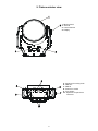
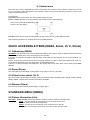
2. Fixture exterior view
1 - Moving head
2 - Tilt lock
3 - Control buttons
4 - Display
5 - Apertures for safety chain
6 - DMX out
7 - DMX in
8 - PowerCon socket
9 - Fuse holder
10 - Apertures for quick-turn
fasteners
3. Installation
Fixtures must be installed by a Qualified electrician in accordance with all
national and local electrical and construction codes and regulation.
3.1 Connection to the mains
For protection from electric shock, the fixture must be earthed!
The Robin Actor 3 ST is equipped with auto-switching power supply that automatically adjusts to any 50-60Hz
AC power source from 100-240 Volts.
If you need to install a suitable plug on the power cord, note that the cores in the power cord are coloured according to the following table. The earth has to be connected!
If you have any doubts about proper installation, consult a qualified electrician.
Core (EU)
Core (US)
Connection
Plug Terminal Marking
Brown
Black
Live L
Light blue
White
Neutral
N
Yellow/Green
Green
Earth
This device falls under class one and must be earthed (grounded)!
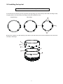
3.2 Installing the top hat
Switch
off the fixture before top hat installation
1.Unscrew the four fastening screws (3) which securing flange (4) to the head (5) and install new flange. Keep
its right position- the cutouts (A) in the flange must look towards the arms.
Original flange
New flange
2.Place the top hat (1) on the head (5), press locks (2) and turn the top hat counter-clockwise until it snap into
slots (B) in the flange.
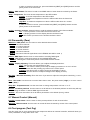
3.3 Rigging the fixture
The overhead installation must always be secured with a secondary safety attachment, e.g. an appropriate
safety rope. This secondary safety attachment must be constructed in a way that no part of the installation can
fall down if the main attachment fails.
When rigging, derigging or servicing the fixture staying in the area below the installation place, on bridges,
under high working places and other endangered areas is forbidden.
The operator has to make sure that safety-relating and machine-technical installations are approved by an expert
before taking into operation for the first time and after changes before taking into operation another time.
The operator has to make sure that safety-relating and machine-technical installations are approved by an
expert after every four year in the course of an acceptance test.
The operator has to make sure that safety-relating and machine-technical installations are approved by a skilled
person once a year.
The fixture should be installed outside areas where persons may walk by or be seated.
IMPORTANT! OVERHEAD RIGGING REQUIRES EXTENSIVE EXPERIENCE, including (but not limited to)
calculating working load limits, installation material being used, and periodic safety inspection of all installation
material and the projector. If you lack these qualifications, do not attempt the installation yourself, but instead
use a professional structural rigger. Improper installation can result in bodily injury or damage to property.
The fixture has to be installed out of the reach of people.
If the fixture shall be lowered from the ceiling or high joists, professional trussing systems have to be used. The
fixture must never be fixed swinging freely in the room.
Caution: Fixture may cause severe injuries when crashing down! If you have doubts concerning the safety of
a possible installation, do not install the moving head!
Before rigging make sure that the installation area can hold a minimum point load of 10 times the fixture’s
weight.
When installing the device, make sure there is no highly inflammable
material (decoration articles, etc.) in a distance of min. 0.4 m.
.
CAUTION!
Use an appropriate clamp to rig the fixture on the truss.
Follow the instructions mentioned at the bottom of the base.
Make sure that the device is fixed properly! Ensure that the
structure (truss) to which you are attaching the fixtures is secure.
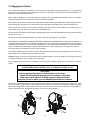
The fixture can be placed directly on the stage floor by means of the removable stand (4) or rigged on a truss
by means of the omega holder (1) and clamp (2) without altering its operation characteristics. Both removable
stand and omega holder can be fastened with two 1/4-turn locks to the bottom of the fixture. Adjust fixture´s
head to desired position and tighten tilt lock (5) to secure the head position.
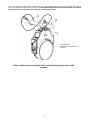
For securing the fixture to the truss install a safety wire that can hold at least 10 times the weight of the fixture.
Use only a safety wire with screw-on snap-hook. Thread the snap-hook through two apertures in the fixture
base and the wire around the truss as shown on the picture below.
1-Safety wire
2-Apertures for safety wire
3-Trust
When installing fixtures side-by-side, avoid illuminating one fixture with
another!
3.4 DMX-512 connection
The fixture is equipped with 5-pin XLR sockets for DMX input and output. Only use a shielded twisted-pair
cable designed for RS-485 and 5-pin XLR-plugs and connectors in order to connect the controller with the
fixture or one fixture with another.
DMX - output
XLR mounting-sockets (rear view):
DMX-input
XLR mounting-plugs (rear view):
1 - Shield
2 - Signal (-)
3 - Signal (+)
4 - Not connected
5 - Not connected
1 - Shield
2 - Signal (-)
3 - Signal (+)
4 - Not connected
5 - Not connected
If you are using the standard DMX controllers, you can connect the DMX output of the controller directly with
the DMX input of the first fixture in the DMX-chain. If you wish to connect DMX controllers with other XLR-outputs, you need to use adapter cables.
Building a serial DMX chain:
Connect the DMX-output of the first fixture in the DMX-chain with the DMX-input of the next fixture. Always
connect one output with the input of the next fixture until all fixtures are connected. Up to 32 fixtures can be
interconnected.
Caution: At the last fixture, the DMX-cable has to be terminated with a terminator. Solder a 120 Ω resistor
between Signal (–) and Signal (+) into a 5-pin XLR-plug and plug it in the DMX-output of the last fixture.
10
4. Control menu map
Default settings=Bold print
Level 1
Level 2
Level 3
DMXA
Set DMXA
001-255
Info
POn Time
Level 4
Level 5
Zoom
Vir C
Dimm
MENU
Total
Reset
DMX In
Pover
0-255
:
Dimm F
Temp
0-255
Current
Highest
High Res
Sw Ver
IC-1
IC-2
IC-3
Pers
DMX Pres
Mode 1
:
Mode 6
DMX In
Wired
Wireless
Display
Turn
On/Off T
On, Off
Contrast
0-100%
Backlight
0-100%
Mic Sens
0...10...19
Fans
Auto, High
Temp Uni
°C, °F
I Ef Pos
Pan
:
Dimm F
Store
Defaults
Test Prg
Manual
Pres Eff
Pover
Pos 1-Pos 3
:
Manual
Sta Alone
Dimmer
Pos 1- Pos 5
Pover
0-255
Dimm F
0-255
Music T
On, Off
Aut Run
Off
Test
Prog 1
Prog 2
Prog 3
Pr Play
Test Prg
Prog 1
11
Level 6
Level 7
Level 1
Level 2
Level 3
Level 4
Level 5
Level 6
Level 7
Prog 1
Step 1
Pan
Prog 2
:
:
Prog 3
Step 40
F.Tim
0-25.5
S.Tim
0-25.5
Prog 2
Prog 3
Pr Edit
COPY
Prg End
Reset
Special
RDM Low
RDM Hight
Wireless
Stat
Unlink
Adjust
DMX Val
Pover
0-255
:
Dimm F
Sw Upd
On, Off
12
0-255
1-40
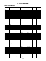
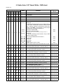
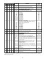
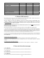
5. Robin Actor 3 ST Smart White - DMX chart
Version 1.0
Mode/Channel
1
-
2
-
3
-
4
-
5
-
6
1
2
3
4
5
Value
No function
No function
No function
No function
10-14
15-19
1
1
1
1
6
Type of
control
No function
0-9
1
Function
20-169
170 - 179
180 - 189
190 - 199
200 - 209
210 - 239
240
241 - 255
Special functions
Reserved
To activate following function, stop in DMX value for
at least 3sec. and shutter must be closed at least
3sec. (Shutter channel 17/9/6/4/4/22 must be at
range of 0-31DMX). The function is active only10
seconds after switching the fixture on.
DMX input: Wired DMX*
DMX input: Wireless DMX*
* Function is active only 10 seconds after switching the fixture on
step
step
Reserved
To activate following reset function, stop in DMX
value for at least 3 sec.
Save current DMX values into fixture **
Zoom reset
Reserved
Total reset
Reserved
Disable "Silent mode" of fans
"Silent mode of fans":fans noise from min. to max.
step
proportional
step
step
step
-
2
2
-
-
-
0-255
Warm White (8 bit) - all zones
Warm white LEDs saturation control (0-100%)
proportional
-
3
-
-
-
-
0-255
Warm White(16 bit) - all zones
Fine warm white LEDs saturation control
proportional
-
4
3
-
-
-
0-255
Cool White (8 bit) - all zones
Cool white LEDs saturation control (0-100%)
proportional
proportional
-
5
-
-
-
-
0-255
Cool white fine (16 bit) - all zones
Fine cool white LEDs saturation control
2
-
-
-
8
7
0-255
Warm White (8 bit) - zone 1
Warm white LEDs saturation control (0-100%)
proportional
3
-
-
-
9
8
0-255
Warm white fine (16 bit) - zone 1
Fine warm white LEDs saturation control
proportional
4
-
-
-
10
9
0-255
Cool white (8 bit) - zone 1
Cool white LEDs saturation control (0-100%)
proportional
5
-
-
-
11 10
0-255
Cool white fine (16 bit) - zone 1
Fine cool white LEDs saturation control
proportional
6
-
-
-
12 11
0-255
Warm White (8 bit) - zone 2
Warm white LEDs saturation control (0-100%)
proportional
proportional
7
-
-
-
13 12
0-255
Warm white fine (16 bit) - zone 2
Fine warm white LEDs saturation control
8
-
-
-
14 13
0-255
Cool white (8 bit) - zone 2
Cool white LEDs saturation control (0-100%)
proportional
9
-
-
-
15 14
0-255
Cool white fine (16 bit) - zone 2
Fine cool white LEDs saturation control
proportional
10
-
-
-
16 15
0-255
Warm White (8 bit) - zone 3
Warm white LEDs saturation control (0-100%)
13
proportional
Mode/Channel
Function
Type of
control
2
3
4
5
11
-
-
-
17 16
0-255
Warm white fine (16 bit) - zone 3
Fine warm white LEDs saturation control
proportional
12
-
-
-
18 17
0-255
Cool white (8 bit) - zone 3
Cool white LEDs saturation control (0-100%)
proportional
13
-
-
-
19 18
0-255
Cool white fine (16 bit) - zone 3
Fine cool white LEDs saturation control
proportional
7
0
1-2
3-4
5-6
7-8
9-10
11-12
13-14
15-16
17-247
14
6
4
2
6
Value
1
19
248
249
250
251
252
253
245
255
Virtual colour wheel & zone effects
No function
White 2800 K
White 3200 K
White 3800 K
White 4200 K
White 4600 K
White 5000 K
White 5600 K
White 6300 K
Warm white --> Cool white
Speed of the following effects can be controlled by the
Shutter/Strobe channel (DMX values of 96-127)
Rainbow effect (with fade time)
Rainbow effect
Zone effect 1
Zone effect 2
Zone effect 3
Zone effect 4
Zone effect 5
Zone effect 6
step
step
step
step
step
step
step
step
step
proportional
step
step
step
step
step
step
step
step
15
7
5
3
2
20
0 - 255
Zoom (8 bit)
Zoom from min. to max. beam angle
proportional
16
8
-
-
3
21
0 - 255
Zoom fine (16 bit)
Fine zooming from min. to max.
proportional
0-31
32-63
64-95
96-111
112-127
17
9
6
4
4
22
128-143
144-159
160-175
176-191
192-223
224-255
Shutter/Strobe
Shutter closed
Strobe effect from slow--> fast (zone 3 only)
Strobe effect from slow--> fast (All zones together)
--------------Set value on Virtual colour wheel--------------
Zone effects+rainbow effects speed control, slow--> fast
Zone effects+rainbow effects speed control, fast--> slow
/opposite direction/
Opening pulses in sequences from slow--> fast
(All zones together)
Closing pulses in sequences from fast--> slow
(All zones together)
Random strobe effect from slow--> fast (random zone)
Random strobe effect from slow--> fast (random zone +
random strobe)
Random strobe effect from slow --> fast (All zones
together)
Shutter open
step
proportional
proportional
proportional
proportional
proportional
proportional
proportional
proportional
proportional
step
18 10
7
5
5
23
0-255
Dimmer (8 bit)
Dimmer intensity from 0% to 100%
proportional
19 11
-
-
6
24
0-255
Dimmer fine (16 bit)
Fine dimming
proportional
** DMX values of all channels are saved into fixture and will be recall after switching the fixture on (without
DMX controller connected).
14
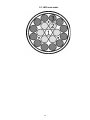
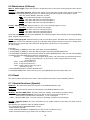
5.1 LED zone order
15
6. Control menu
The Robin Actor 3 ST is equipped with 2-line LCD display which allows to set the fixture´s behaviour according to your needs, obtain information on its operation, test its various parts and lastly program it, if it has to be
used in a stand-alone mode.
Control panel:
[ESCAPE] button used to leave the menu without saving changes.
[NEXT] , [PREV] buttons for moving between menu items and for value adjusting.
Note: Press and hold the [ESCAPE]
button to turn the display
[ENTER] button used to enter the selected menu (menu item) and to confirm adjusted value.
After switching the fixture on, display shows current DMX address.
QUICK ACCESSIBLE ITEMS (DMXA, Zoom, Vir C, Dimm)
6.1 Addressing (DMXA)
Set DMXA- Use this menu item to set the DMX start address of the fixture, which is defined as the first channel
from which the Robin Actor 3 ST will respond to the controller.
If you set, for example, the address 36, the Robin Actor 6 will use channels 36 - 67 for control (if Mode 1 is
selected).
Please, be sure that you do not have any overlapping channels in order to control each Robin Actor 3 ST correctly and independently from any other fixture on the DMX data link.
If there is no data received at the DMX input, the display will start to flash "0001” with actually stored DMX
address.
6.2 Zoom (Zoom)
The motorized zoom with silent running allows zoom range of 8°-53° (1/2 beam).
6.3 Virtual colour wheel (Vir C)
The virtual colour wheel allows choosing of 237 pre-defined colours including whites 2700K, 3200K, 4200K,
5600K, 8000K ; rainbow effect and six zone-effects available.
6.4 Dimmer (Dimm)
The electronic dimmer allows fine dimming in range 0-100%.
STANDARD MENU (MENU)
6.5 Fixture information (Info)
Pon Time - Power on time. Select this menu to read the number of fixture operation hours.
Total - The item shows the total number of the operation hours since
the Robin Actor 3 ST has been fabricated.
Reset - The item shows the number of the operation hours that the Robin Actor 3 ST has been powered on since the counter was last reset.
16
In order to reset this counter to 0, press and hold both [NEXT] and [PREV] buttons and the [Enter] button at the same time.
DMX In - DMX readout. The menu is used to read DMX values of each channel received by the fixture.
Temp - Temperature. The menu shows temperature in the LED module.
Current - A current temperature of the LED module.
Highest - A maximum temperature of the the LED module since the fixture has
been fabricated.
High Res - A maximum temperature of the the LED module since the counter
was last reset.
In order to reset this counter, press and hold both [NEXT] and [PREV] buttons and the [Enter] button at the same time.
Sw Ver - Software versions. Select this item to read the software version of the fixture modules.
IC-1 - A zoom processor on the main board in the fixture arm.
IC-2 - A display processor on the display board in the fixture base.
IC-3 - LED control processor on the board in the fixture head.
6.6 Personality (Pers)
DMX Pres - DMX preset. Use the menu to select desired channel mode.
Mode 1 - 19 control channels
Mode 2 - 11 control channels
Mode 3 - 7 control channels
Mode 4 - 5 control channels
Mode 5 - 19 control channels
Mode 6 - 24 control channels (equivalent to the LEDWash 300 SW in mode 1)
DMX In - DMX input. Use the menu to select mode of receiving DMX signal.
Wired - DMX signal is received by means of the standard DMX cable.
Wireless - DMX signal is received by means of the inbuilt wireless module.
Display - Display adjusting. This menu allows you to adjust the display behaviour.
Turn - This function turns the display by 180°.
On/Off T - This function allows you to keep the display permanent on or turn it off two
minutes after last pressing any button on the control panel.
Contrast- Use this function to adjust contrast of the display (0-100%).
Backlight- Use this function to adjust backlight of the display (0-100%).
Mic Sens - Microfon sensitivity. Enter the menu if you want to adjust the microphone sensitivity ( 1-max.,
19-min.).
Fans - Fan mode. Use the menu to set the fixture fans to max. fan power mode ("High") or to auto- control
mode ("Auto").
Temp Uni - Temperature unit. Use the menu item to change temperature unit from °C to °F.
I Ef Pos - Init effect positions. Use the menu to set all effects to the desired positions at which they will stay
after switching the fixture on without DMX signal connected.
Defaults - The menu item allows to set all fixture parameters to the default (factory) values.
6.7 Manual Control (Manual)
Pres Eff - Preset effects. Use the menu to show preset positions of each channel effect.
Manual C - Manual control. Use the menu to control all fixture channels by means of the control panel.
6.8 Test program (Test Prg)
Use this menu item to run a special demo-test sequences without an external controller, which will show you
some possibilities of using Robin Actor 3 ST.
17
6.9 Stand-alone (St Alone)
Music T - Music trigger. Select this function to enable the sound control of the running program via the built-in
microphone.
Auto Run - Presetting playback. This function allows you to select the program which will be played in the
stand-alone mode after switching the fixture on. Selected program will be played continuously in a loop.
Off - The option disables „Auto Run” function.
Test - The option will start built-in test program.
Prog 1 - The option will start user-created program 1
Prog 2 - The option will start user-created program 2
Prog 3 - The option will start user-created program 3
Pr Play - Playing program. Select this menu to run a user-created program in a loop.
Test Prg - The option runs built-in test program.
Prog 1 - The option runs user-created program 1
Prog 2 - The option runs user-created program 2
Prog 3 - The option runs user-created program 3
Select the program you wish and press [ENTER]. The selected program starts running. By Pressing [ENTER]
again, program pauses running.
Pr Edit - Editing program. Select this menu to edit or create the program. The Robin Actor 3 ST has one builtin program and one user-editable program up to 40 steps. Each program step has a step time - during which
effects last in the current step and a fade time- during which effects move to new positions.
To edit program:
Procedure:
1. Press [NEXT] or [PREV] to select the menu "Edit" and press [ENTER].
2. Press [NEXT] or [PREV] to select the desired program step and press [ENTER] button.
3. Press [NEXT] or [PREV] to select the desired item and press [ENTER] button. Now you can edit by [NEXT]
or [PREV] buttons the DMX value (0-255) for selected item:
Prg End. a total number of the program steps (value 1-40). This value you should be set before starting of programming (e.g. if you want to create program with the 10 steps,
set Prg End=10).
F.Tim a fade time (0-25.5 sec)
S.Tim a step time (0-25.5 sec)
COPY copying the current prog. step to
the next prog. step
4. Press [ENTER] button to confirm adjusted value .
5. Press [ESCAPE] button, select next prog. step, press [ENTER] button and repeat steps 3-5.
6.10 Reset
This option enables the Robin Actor 3 ST to index all effects and return to their standard positions.
6.11 Special functions (Special)
RDM Low - This menu item shows the first part of the RDM identification code.
RDM High - This menu item shows the second part of the RDM identification code.
Wireless - Wireless DMX status. The menu serves for reading of the wireless operation status.
r.InF. - Wireless DMX information. The menu item shows level of received signal in %.
If the fixture is not linked to the transmitter, “no.LI” is displayed.
r.UnL. - Wireless DMX unlink. The item serves for unlinking the fixture from transmitter.
Sw Upd - Software update. The menu item allows you to update software in the fixture via either serial or
USB port of PC.
The following are required in order to update software:
- PC running Windows 95/98/2000/XP/7 or Linux
- DMX Software Uploader
- Flash cable RS232/DMX No.13050624 (if you want to use a serial port of PC)
- Robe Universal Interface (if you want to use an USB port of PC)
18
Note 1: Software update should execute a qualified person. If you lack qualification, do not attempt the update
yourself and ask for help your ROBE distributor.
Note 2: DMX address, , programs 1-3 and all items in the menu "Pers" will be set to their default (factory)
values.
To update software in the fixture:
I. Installation of the DMX Software Uploader.
1. DMX Software Uploader program is available from the ROBE web site at WWW.robe.cz.
2. Make a new directory ( e.g. Robe_Uploader) on your hard disk and download the software to it.
3. Unpack the program to the directory.
II.Fixture software updating.
1.Determine which of your ports is available on your PC and connect it:
- with the DMX input of the fixture if you using the flash cable RS232/DMX
- with the DMX output of the Robe Universal Interface if you using the USB cable.
Disconnect the fixture from the other fixtures in a DMX chain. Turn both the computer and
the fixture on. Make sure the lamp is switched off (only if the fixture involves a lamp).
2. Switch the fixture to the updating mode by selecting the "SW Upd " item and press [ENTER].
Note: If you do not want to continue in software update, you have to switch off and on the fixture
to escape from this menu.
We recommend to cancel all running programs before starting the Software Uploader.
3. Run the Software Uploader program. Select desired COM and then click on the Connect button.
(Select COM if the serial port is used or Robe Universal Interface if the USB port is used).
If the connection is OK, click on the “Start Uploading button“ to start uploading. It will take several
minutes to perform software update.
If the option "Incremental Update" is not checked, all processors will be updated (including
processors with the same software version).
If you wish to update only later versions of processors, check the “Incremental Update box“.
Avoid interrupting the process. Update status is being displayed in the Info Box window.
When the update is finished, the line with the text “The fixture is successfully updated“ will appear in
this window and the fixture will reset with the new software.
Note: In the case of an interruption of the upload process (e.g. power cut), the fixture keeps the updating mode
and you have to repeat the software update again.
7. RDM
This fixture supports RDM operation. RDM (Remote Device Management) is a bi-directional communications
protocol for use in DMX512 control systems, it is the new open standard for DMX512 device configuration and
status monitoring.
The RDM protocol allows data packets to be inserted into a DMX512 data stream without adversely affecting
existing non-RDM equipment. By using a special „Start Code,“ and by complying with the timing specifications
for DMX512, the RDM protocol allows a console or dedicated RDM controller to send commands to and receive
messages from specific moving lights.
RDM allows explicit commands to be sent to a device and responses to be received from it.
The list of commands for Robin Actor 3 ST is the following.
Parameter ID
Discovery command SET command
DISC_UNIQUE_BRANCH
*
DISC_MUTE
*
DISC_UN_MUTE
*
GET command
DEVICE_INFO
*
SUPPORTED_PARAMETERS
*
SOFTWARE_VERSION_LABEL
*
DMX_START_ADDRESS
*
*
IDENTIFY_DEVICE
*
*
DEVICE_MODEL_DESCRIPTION
*
MANUFACTURER_LABEL
*
*
DEVICE_LABEL
19
*
SENSOR_DEFINITION
*
SENSOR_VALUE
*
DISPLAY_INVERT
*
*
DISPLAY_LEVEL
*
*
DEVICE_RESET
*
DMX_PERSONALITY
*
*
DMX_PERSONALITY_DESCRIPTION
*
STATUS_MESSAGES
*
STATUS_ID_DESCRIPTION
*
DEVICE_HOURS
*
PARAMETER_DESCRIPTION
*
8. Wireless DMX operation
The wireless version of the Actor 3 ST is equipped with the Lumen Radio CRMX module and antenna for
receiving DMX signal. CRMX module operates on the 2.4 GHz band.
The item " Wireless " from the menu "DMX Input" allows you to activate receiving of wireless DMX (Pers-> DMX In -->Wireless.). The options from the "DMX Input" menu are stated in DMX chart as well (channel
Power/Special functions , range of 10-19 DMX). If DMX input option is changed by DMX command, the change
is permanently written into fixture´s memory.
DMX range of 10-19 switching fixture to the wired/wireless operation is active only during first 10 seconds after switching the fixture on.
After switching the fixture on, the fixture checks both modes of receiving DMX in the following order:
1. For the first five seconds, the fixture receives DMX signal from the wired input. If the Power/Special functions
channel is set at some DMX input option, the fixture will receive DMX value according to this option. If DMX input
option is set to the wired input , this option is saved and checking procedure is finished. If DMX input option is
not set, the fixture continues next 5 seconds in scanning wireless DMX signal-see point 2.
2. For the next 5 seconds the fixture receives wireless DMX signal and again detects if the Power/Special
functions channel is set at some DMX input option, if not, the fixture will take option which is set in the fixture
menu "DMX Input".
To link the fixture with DMX transmitter.
The fixture can be only linked with the transmitter by running the link procedure at DMX transmitter .
After linking , the level of DMX signal ( 0-100 %) is displayed in the menu item “Wireless “ (Special -->Wireless
-->Stat).
To unlink the fixture from DMX transmitter.
The fixture can be unlinked from receiver via the menu item “ Unlink “ (Special --> Wireless --> Unlink).
9. Error and information messages
L. Z. 1 Short Err.
The message informs you that short circuit has occured on the PCB of LED zone 1.
L. Z. 2 Short Err
The message informs you that short circuit has occured on the PCB of LED zone 2.
L. Z. 3 Short Err
The message informs you that short circuit has occured on the PCB of LED zone 3.
20
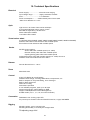
10. Technical Specifications
Electrical
Power supply:.........................electronic auto-ranging
Input voltage range:............... supply 100-240V, 50-60Hz
Fuse:.......................................T 3.15A/250V ~
Power consumption *:........ 200W @230V,power factor=0,96
*Allow for a deviation of +/-10%
Optic
Light source: 19 Osram Ostar ww/cw multichips
3 zones with individual colour control of each
Min LED life expectancy: 20.000 hours
Warm white LEDs: 2600K
Cool white LEDs: 7500K
Virtual colour wheel
pre-defined whites (2800K, 3200K, 3800K, 4200K,4600K, 5000K, 5600K and 6300K)
Rainbow effect with in both directions with variable speed
Zone effects in both directions with variable speed
Strobe
All LED zones together:
Strobe effect with variable speed (0.3 - 20Hz)
Random strobe pulse-effect with variable speed
Opening/closing pulse effect with variable speed
Independent strobe effect with variable speed (0.3 - 20Hz) at zone 3
Random strobe and random LED zone effect
Dimmer
Smooth dimmer from 0 - 100 %
Zoom
Control
Connection
Motorized zoom
2-line LCD display & 4 push buttons
Readout fixture usage, receiving DMX values, temperatures, etc
Built-in analyzer for easy fault finding, error messages
Built-in demo sequences
Silent fans cooling,
Stand-alone operation
3 user editable programs, each up to 40 steps
Supported protocols: USITT DMX 512, RDM,
Support of RDM (Remote Device Management)
6 DMX modes (19, 11, 7, 5, 19, 24 control channels)
DMX data in/out: Locking 5-pin XLR
AC power input: Chassis connector Neutrik PowerCon, A-type, NAC3MPA
Rigging
Mounting points: pair of 1/4-turn locks
Mounting horizontally or vertically via Omega holder
Tilt adjusting range: 230°
21
Temperatures
Maximum ambient temperature : 45° C
Maximum housing temperature : 75° C
Distances
Min. distance from flammable surfaces: 0.4 m
Min. distance to lighted object: 1 m
Total heat dissipation
682 BTU/h (calculated)
Weight (net)
5.2 kg (without floor stand)
6.3 kg (with floor stand)
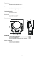
Dimensions (mm)
Accessories
Omega holder (P/N 99010420)...........................................1 piece
Floor stand (P/N 99013521)................................................1 piece
EggCrate Robin 300 LEDWash-black (No. 19520089)...... 1 piece
Optional accessories
Top hat -black (No.10980102)
Top hat -white (No.10980104)
22
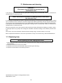
11. Maintenance and cleaning
DANGER !
Disconnect from the mains before starting any
maintenance work
A soft lint-free cloth moistened with any good glass cleaning fluid is recommended, under no circumstances
should alcohol or solvents be used!
Never use alcohol or solvents for cleaning lenses in the fixture!
Use wet cloth only.
It is absolutely essential that the fixture is kept clean and that dust, dirt and smoke-fluid residues must not build
up on or within the fixture. Otherwise, the fixture‘s light-output will be significantly reduced. Regular cleaning will
not only ensure the maximum light-output, but will also allow the fixture to function reliably throughout its life.
A soft lint-free cloth moistened with any good glass cleaning fluid is recommended, under no circumstances
should alcohol or solvents be used!
The front transparent cover may require monthly cleaning as smoke-fluid tends to building up residues, reducing the light-output very quickly. The cooling fans should be cleaned according to the situation (at least annually).
The interior of the base should be cleaned at least annually using a vacuum-cleaner or an air-jet.
More complicated maintenance and service operations are only to be carried out by authorized distributors.
11.1 Replacing fuse
Before replacing the fuse, unplug mains lead!
1. Remove the fuse holder on the bottom side of the fixture arm with a fitting screwdriver from the housing
(anti-clockwise).
2. Remove the old fuse from the fuse holder.
3. Install the new fuse in the fuse holder (only the same type and rating).
4. Replace the fuse holder in the housing and fix it.
Specifications are subject to change without notice.
September 19, 2013
23
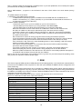
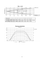
12. Photometric diagrams
24
25
26