1
O w n e r ’s M a n u a l
EN
SPECIAL MESSAGE SECTION
PRODUCT SAFETY MARKINGS: Yamaha electronic
products may have either labels similar to the graphics
shown below or molded/stamped facsimiles of these graphics on the enclosure. The explanation of these graphics
appears on this page. Please observe all cautions indicated
on this page and those indicated in the safety instruction section.
CAUTION
RISK OF ELECTRIC SHOCK
DO NOT OPEN
CAUTION: TO REDUCE THE RISK OF ELECTRIC SHOCK.
DO NOT REMOVE COVER (OR BACK).
NO USER-SERVICEABLE PARTS INSIDE.
REFER SERVICING TO QUALIFIED SERVICE PERSONNEL.
The exclamation point within the equilateral triangle is intended to alert the
user to the presence of important operating and maintenance (servicing) instructions in the literature accompanying the
product.
The lightning flash with arrowhead symbol, within the equilateral triangle, is
intended to alert the user to the presence
of uninsulated “dangerous voltage”
within the product’s enclosure that may
be of sufficient magnitude to constitute a
risk of electrical shock.
IMPORTANT NOTICE: All Yamaha electronic products
are tested and approved by an independent safety testing
laboratory in order that you may be sure that when it is properly installed and used in its normal and customary manner,
all foreseeable risks have been eliminated. DO NOT modify
this unit or commission others to do so unless specifically
authorized by Yamaha. Product performance and/or safety
standards may be diminished. Claims filed under the
expressed warranty may be denied if the unit is/has been
modified. Implied warranties may also be affected.
SPECIFICATIONS SUBJECT TO CHANGE: The information contained in this manual is believed to be correct at
the time of printing. However, Yamaha reserves the right to
change or modify any of the specifications without notice or
obligation to update existing units.
ENVIRONMENTAL ISSUES: Yamaha strives to produce
products that are both user safe and environmentally
friendly. We sincerely believe that our products and the production methods used to produce them, meet these goals. In
keeping with both the letter and the spirit of the law, we
want you to be aware of the following:
Battery Notice: This product MAY contain a small nonrechargeable battery which (if applicable) is soldered in
place. The average life span of this type of battery is approximately five years. When replacement becomes necessary,
contact a qualified service representative to perform the
replacement.
Warning: Do not attempt to recharge, disassemble, or
incinerate this type of battery. Keep all batteries away from
children. Dispose of used batteries promptly and as regulated by applicable laws.
Note: In some areas, the servicer is required by law to return
the defective parts. However, you do have the option of having the servicer dispose of these parts for you.
Disposal Notice: Should this product become damaged
beyond repair, or for some reason its useful life is considered to be at an end, please observe all local, state, and federal regulations that relate to the disposal of products that
contain lead, batteries, plastics, etc.
NOTICE: Service charges incurred due to lack of knowledge relating to how a function or effect works (when the
unit is operating as designed) are not covered by the manufacturer’s warranty, and are therefore the owners responsibility. Please study this manual carefully and consult your
dealer before requesting service.
NAME PLATE LOCATION: The graphic below indicates
the location of the name plate. The model number, serial
number, power requirements, etc., are located on this plate.
You should record the model number, serial number, and the
date of purchase in the spaces provided below and retain this
manual as a permanent record of your purchase.
Model
Serial No.
Purchase Date
92-469- 1 (rear)
2
CP1 Owner’s Manual
Explanation of Graphical Symbols
The lightning flash with arrowhead symbol
within an equilateral triangle is intended to alert
the user to the presence of uninsulated
“dangerous voltage” within the product’s
enclosure that may be of sufficient magnitude to
constitute a risk of electric shock to persons.
CAUTION
RISK OF ELECTRIC SHOCK
DO NOT OPEN
The exclamation point within an equilateral
triangle is intended to alert the user to the
presence of important operating and
maintenance (servicing) instructions in the
literature accompanying the product.
CAUTION: TO REDUCE THE RISK OF
ELECTRIC SHOCK, DO NOT REMOVE
COVER (OR BACK). NO USER-SERVICEABLE
PARTS INSIDE. REFER SERVICING TO
QUALIFIED SERVICE PERSONNEL.
The above warning is located on the rear of the unit.
IMPORTANT SAFETY INSTRUCTIONS
1
2
3
4
5
6
7
8
9
10
Read these instructions.
Keep these instructions.
Heed all warnings.
Follow all instructions.
Do not use this apparatus near water.
Clean only with dry cloth.
Do not block any ventilation openings. Install in
accordance with the manufacturer’s instructions.
Do not install near any heat sources such as radiators,
heat registers, stoves, or other apparatus (including
amplifiers) that produce heat.
Do not defeat the safety purpose of the polarized or
grounding-type plug. A polarized plug has two blades
with one wider than the other. A grounding type plug
has two blades and a third grounding prong. The wide
blade or the third prong are provided for your safety. If
the provided plug does not fit into your outlet, consult
an electrician for replacement of the obsolete outlet.
Protect the power cord from being walked on or pinched
particularly at plugs, convenience receptacles, and the
point where they exit from the apparatus.
11
12
13
14
Only use attachments/accessories specified by the
manufacturer.
Use only with the cart, stand,
tripod, bracket, or table specified
by the manufacturer, or sold with
the apparatus. When a cart is used,
use caution when moving the cart/
apparatus combination to avoid
injury from tip-over.
Unplug this apparatus during lightning storms or when
unused for long periods of time.
Refer all servicing to qualified service personnel.
Servicing is required when the apparatus has been
damaged in any way, such as power-supply cord or plug
is damaged, liquid has been spilled or objects have
fallen into the apparatus, the apparatus has been
exposed to rain or moisture, does not operate normally,
or has been dropped.
WARNING
TO REDUCE THE RISK OF FIRE OR ELECTRIC SHOCK, DO NOT EXPOSE THIS APPARATUS TO RAIN OR MOISTURE.
(UL60065_03)
CP1 Owner’s Manual
3
PRECAUTIONS
PLEASE READ CAREFULLY BEFORE PROCEEDING
* Please keep this manual in a safe place for future reference.
WARNING
Always follow the basic precautions listed below to avoid the possibility of serious injury or even death from electrical
shock, short-circuiting, damages, fire or other hazards. These precautions include, but are not limited to, the following:
Power supply/Power cord
Water warning
• Only use the voltage specified as correct for the instrument. The required voltage
is printed on the name plate of the instrument.
• Check the electric plug periodically and remove any dirt or dust which may have
accumulated on it.
• Use only the supplied power cord/plug.
• Do not place the power cord near heat sources such as heaters or radiators, and
do not excessively bend or otherwise damage the cord, place heavy objects on
it, or place it in a position where anyone could walk on, trip over, or roll anything
over it.
• Be sure to connect to an appropriate outlet with a protective grounding
connection. Improper grounding can result in electrical shock.
• Do not expose the instrument to rain, use it near water or in damp or wet
conditions, or place containers on it containing liquids which might spill into
any openings. If any liquid such as water seeps into the instrument, turn off the
power immediately and unplug the power cord from the AC outlet. Then have the
instrument inspected by qualified Yamaha service personnel.
• Never insert or remove an electric plug with wet hands.
Fire warning
• Do not put burning items, such as candles, on the unit.
A burning item may fall over and cause a fire.
If you notice any abnormality
Do not open
• Do not open the instrument or attempt to disassemble the internal parts or
modify them in any way. The instrument contains no user-serviceable parts. If it
should appear to be malfunctioning, discontinue use immediately and have it
inspected by qualified Yamaha service personnel.
• If the power cord or plug becomes frayed or damaged, or if there is a sudden
loss of sound during use of the instrument, or if any unusual smells or smoke
should appear to be caused by it, immediately turn off the power switch,
disconnect the electric plug from the outlet, and have the instrument inspected
by qualified Yamaha service personnel.
CAUTION
Always follow the basic precautions listed below to avoid the possibility of physical injury to you or others, or damage
to the instrument or other property. These precautions include, but are not limited to, the following:
Power supply/Power cord
Location
• Always connect the three-pin attachment plug to a properly grounded power
source. (For more information about the main power supply, see page 10.)
• When removing the electric plug from the instrument or an outlet, always hold
the plug itself and not the cord. Pulling by the cord can damage it.
• Remove the electric plug from the outlet when the instrument is not to be used
for extended periods of time, or during electrical storms.
• Do not connect the instrument to an electrical outlet using a multiple-connector.
Doing so can result in lower sound quality, or possibly cause overheating in the
outlet.
• Do not expose the instrument to excessive dust or vibrations, or extreme cold or
heat (such as in direct sunlight, near a heater, or in a car during the day) to
prevent the possibility of panel disfiguration or damage to the internal
components.
• Do not use the instrument in the vicinity of a TV, radio, stereo equipment, mobile
phone, or other electric devices. Otherwise, the instrument, TV, or radio may
generate noise.
• Do not place the instrument in an unstable position where it might accidentally
fall over.
• Before moving the instrument, remove all connected cables.
• When setting up the product, make sure that the AC outlet you are using is
easily accessible. If some trouble or malfunction occurs, immediately turn off
the power switch and disconnect the plug from the outlet. Even when the power
switch is turned off, electricity is still flowing to the product at the minimum
level. When you are not using the product for a long time, make sure to unplug
the power cord from the wall AC outlet.
(1)-12
4
CP1 Owner’s Manual
1/2
Connections
Saving data
• Before connecting the instrument to other electronic components, turn off the
power for all components. Before turning the power on or off for all components,
set all volume levels to minimum. Also, be sure to set the volumes of all
components at their minimum levels and gradually raise the volume controls
while playing the instrument to set the desired listening level.
Maintenance
• When cleaning the instrument, use a soft, dry cloth. Do not use paint thinners,
solvents, cleaning fluids, or chemical-impregnated wiping cloths.
• During extreme changes in temperature or humidity, condensation may occur
and water may collect on the surface of the instrument. If water is left, the
wooden parts may absorb the water and be damaged. Make sure to wipe any
water off immediately with a soft cloth.
Saving and backing up your data
• The data in the instrument’s Edit Buffer (see page 39) will be lost when it is
turned off. If you wish to keep settings you have made within the Edit Buffer for
use later on, therefore, be sure to store them in User Memory (see page 39) or
save them externally on a USB flash-memory device, a computer, or the like. It
should also be noted that data stored in User Memory can also be lost if the CP1
is damaged or used incorrectly. Accordingly, it is wise to make a copy of
important data on an external memory device.
• Never attempt to turn off the power while data is being written to Flash ROM
(while an “Executing...” message is shown). Turning the power off in loss of all
user data and may cause the system to freeze (due to corruption of data in the
Flash ROM). This means that this instrument may not be able to start up
properly, even when turning the power on next time.
Handling caution
• Do not insert a finger or hand in any gaps on the instrument.
• Never insert or drop paper, metallic, or other objects into the gaps on the panel
or keyboard. If this happens, turn off the power immediately and unplug the
power cord from the AC outlet. Then have the instrument inspected by qualified
Yamaha service personnel.
• Do not place vinyl, plastic or rubber objects on the instrument, since this might
discolor the panel or keyboard.
• Do not rest your weight on, or place heavy objects on the instrument, and do not
use excessive force on the buttons, switches or connectors.
• Do not use the instrument/device or headphones for a long period of time at a
high or uncomfortable volume level, since this can cause permanent hearing
loss. If you experience any hearing loss or ringing in the ears, consult a
physician.
Yamaha cannot be held responsible for damage caused by improper use or modifications to the instrument, or data that is lost or destroyed.
Always turn the power off when the instrument is not in use.
About the latest Firmware Version
Yamaha may from time to time update firmware of the product and the other associated software without notice for improvement. We recommend that you check our
web site for later releases and upgrade your firmware of the CP1 or the associated software.
http://www.yamahasynth.com/
Note that the explanations in this Owner’s Manual apply to the version of firmware when this Owner’s Manual was produced. For details about the additional functions
due to later releases, refer to the above website.
(1)-12
2/2
CP1 Owner’s Manual
5
Welcome
Thank you for choosing the Yamaha CP1 Stage Piano. This stage piano features a rich spectrum of piano voices,
amplifier simulators, and effectors that faithfully reproduce the characteristics of classic instruments, and by combining
these building blocks in whatever way you desire, you can easily create a vast range of piano sounds — from the
standard to the truly unique — with this one single instrument. Whether used to perform live or in the studio, the CP1 will
open up a whole new world of sonic possibilities.
In order that you can take full advantage of the advanced, highly-convenient functions that the instrument has to offer, we
strongly recommend that you read this owner’s manual carefully. In addition, please keep this manual in a safe place so
that you can refer back to it whenever needed.
Package Contents
•
•
•
•
•
•
Power cord
Pedal unit
Illustrated Guide to the CP1 booklet
Owner’s Manual (this booklet)
Data List booklet
Software DVD*
*: For details regarding the DVD provided, please refer to page 68.
Reference Materials
Makeup
The following booklets have been included in order to help you become familiar with your new stage piano.
Illustrated Guide to the CP1 booklet
In the full-color Illustrated Guide to the CP1 booklet, you will find detailed descriptions of the piano voices, amplifier
simulators, and effectors used within this stage piano to produce its high-quality sounds. If you wish to know how the CP1
does its magic, this is the best place to start.
Owner’s Manual (this booklet)
This manual provides a detailed description of basic CP1 functions, how to setup and use the instrument, and the various
parameters that can be modified.
Data List booklet
The Data List booklet provides a list of all CP1 presets (or Performances); a breakdown of the piano voice types,
modulation effects, amplifier simulators, and compressors used to setup these presets and to create original piano
sounds; a list of the parameters used to configure each of these elements; and MIDI-related reference material.
SPECIAL NOTICE
• The contents of this Owner’s Manual and the copyrights thereof are under exclusive ownership by Yamaha Corporation.
• The illustrations and screens as shown in this Owner’s Manual are for instructional purposes only, and may appear somewhat different from
those on your instrument. and may appear somewhat different from those on your instrument.
• This product incorporates and bundles computer programs and contents in which Yamaha owns copyrights or with respect to which it has
license to use others’ copyrights. Such copyrighted materials include, without limitation, all computer software, style files, MIDI files, WAVE
data, musical scores and sound recordings. Any unauthorized use of such programs and contents outside of personal use is not permitted
under relevant laws. Any violation of copyright has legal consequences. DON’T MAKE, DISTRIBUTE OR USE ILLEGAL COPIES.
• This device is capable of using various types/formats of music data by optimizing them to the proper format music data for use with the device
in advance. As a result, this device may not play them back precisely as their producers or composers originally intended.
• Copying of the commercially available musical data including but not limited to MIDI data and/or audio data is strictly prohibited except for
your personal use.
• Windows is the registered trademark of Microsoft® Corporation.
• Apple, Mac and Macintosh are trademarks of Apple Inc., registered in the U.S. and other countries.
• Steinberg and Cubase are the registered trademarks of Steinberg Media Technologies GmbH.
• The company names and product names in this manual are the trademarks or registered trademarks of their respective companies.
6
CP1 Owner’s Manual
Principal Features of the CP1
Authentic acoustic-piano sounds of unparalleled quality
Building on Yamaha’s decades of accomplishment in the production of stage pianos, we have delicately adjusted of the
sound of each individual key, realized perfect balance over the full length of the keyboard, and even reproduced the
harmonic action of the strings and soundboards of authentic acoustic pianos in response to pedal operation. Thanks to
the application of this skill and expertise, the CP1 can just as easily deliver rich piano tones ideal for solo performances
as ever-present sounds well suited for playing within an ensemble.
Electric-piano sounds reproduced with breath-taking precision
By analyzing the sound-producing mechanism of classic electric pianos using cutting-edge technologies, we have been
able to achieve an extremely smooth response in the CP1 keyboard. Furthermore, our painstaking modeling not only of
original preamps, power amplifiers, and speakers — but also of external effectors responsible for the rich variety of tones
indispensable to quality sound production — has made it possible to faithfully reproduce many electric piano sounds
now regarded as classics.
Weighted wooden keyboard with synthetic ivory keytops
Boasting a weighted hammer-action design and synthetic ivory keytops, the CP1’s 88-key wooden keyboard effortlessly
reproduces the feel of acoustic and classic electric pianos.
Customize function for totally original piano sounds (see page 19)
Allowing you to freely build your own acoustic and electric pianos from a rich selection of piano types, amplifiers, and
effectors, the CP1’s customize function makes easy work of recreating standard vintage settings or realizing unique,
original piano sounds. With your instruments assembled, you can then adjust various parameters to create an even more
diverse range of exciting piano sounds.
Convenient master-keyboard function (see page 52)
Using the CP1’s master-keyboard function, which has been specially crafted for use on-stage, up to four virtual zones
can be setup along the keyboard and assigned to four different tone generators, including other MIDI instruments.
CP1 Owner’s Manual
7
Contents
Setting Up
10
Connecting the Power Cord . . . . . . . . . . . . . . . . . . . . . . . . . . . . . . . . . . . . . . . . . . . . . . . . . . 10
Connecting Audio Equipment . . . . . . . . . . . . . . . . . . . . . . . . . . . . . . . . . . . . . . . . . . . . . . . . . 11
Monitoring with Amplifiers or Powered Speakers . . . . . . . . . . . . . . . . . . . . . . . . . . . . . . . . . 11
Listening via a Mixer . . . . . . . . . . . . . . . . . . . . . . . . . . . . . . . . . . . . . . . . . . . . . . . . . . . . . . . 11
Connecting Pedals . . . . . . . . . . . . . . . . . . . . . . . . . . . . . . . . . . . . . . . . . . . . . . . . . . . . . . . . . . 12
Turning on the CP1. . . . . . . . . . . . . . . . . . . . . . . . . . . . . . . . . . . . . . . . . . . . . . . . . . . . . . . . . . 13
Adjusting the Display Brightness . . . . . . . . . . . . . . . . . . . . . . . . . . . . . . . . . . . . . . . . . . . . . . 14
Adjusting the Volume. . . . . . . . . . . . . . . . . . . . . . . . . . . . . . . . . . . . . . . . . . . . . . . . . . . . . . . . 14
Playing Demonstration Songs
15
Component Names & Functions
16
Top Surface . . . . . . . . . . . . . . . . . . . . . . . . . . . . . . . . . . . . . . . . . . . . . . . . . . . . . . . . . . . . . . . . 16
Rear Panel . . . . . . . . . . . . . . . . . . . . . . . . . . . . . . . . . . . . . . . . . . . . . . . . . . . . . . . . . . . . . . . . . 18
Internal Design of the CP1
19
Principal Components . . . . . . . . . . . . . . . . . . . . . . . . . . . . . . . . . . . . . . . . . . . . . . . . . . . . . . . 19
Tone Generator . . . . . . . . . . . . . . . . . . . . . . . . . . . . . . . . . . . . . . . . . . . . . . . . . . . . . . . . . . . . . 19
Roles the Tone Generator’s Blocks & Parameters . . . . . . . . . . . . . . . . . . . . . . . . . . . . . . . . 20
Makeup of Performance Memory . . . . . . . . . . . . . . . . . . . . . . . . . . . . . . . . . . . . . . . . . . . . . 21
Controller Section. . . . . . . . . . . . . . . . . . . . . . . . . . . . . . . . . . . . . . . . . . . . . . . . . . . . . . . . . . . 23
Basic CP1 Operations . . . . . . . . . . . . . . . . . . . . . . . . . . . . . . . . . . . . . . . . . . . . . . . . . . . . . . . 24
Changing Pages . . . . . . . . . . . . . . . . . . . . . . . . . . . . . . . . . . . . . . . . . . . . . . . . . . . . . . . . . . 24
Changing & Setting Parameter Values . . . . . . . . . . . . . . . . . . . . . . . . . . . . . . . . . . . . . . . . . 24
Setting Names. . . . . . . . . . . . . . . . . . . . . . . . . . . . . . . . . . . . . . . . . . . . . . . . . . . . . . . . . . . . 25
Entering Note Numbers. . . . . . . . . . . . . . . . . . . . . . . . . . . . . . . . . . . . . . . . . . . . . . . . . . . . . 25
Edit Indicator . . . . . . . . . . . . . . . . . . . . . . . . . . . . . . . . . . . . . . . . . . . . . . . . . . . . . . . . . . . . . 26
Exiting from the Current Screen . . . . . . . . . . . . . . . . . . . . . . . . . . . . . . . . . . . . . . . . . . . . . . 26
Quick Start Guide
27
Using CP1 Performances. . . . . . . . . . . . . . . . . . . . . . . . . . . . . . . . . . . . . . . . . . . . . . . . . . . . . 27
Selecting a Performance. . . . . . . . . . . . . . . . . . . . . . . . . . . . . . . . . . . . . . . . . . . . . . . . . . . . 27
Using Knobs 1 to 6 to Change the Sound . . . . . . . . . . . . . . . . . . . . . . . . . . . . . . . . . . . . . . 28
Using Pedals . . . . . . . . . . . . . . . . . . . . . . . . . . . . . . . . . . . . . . . . . . . . . . . . . . . . . . . . . . . . . 30
Bending Notes . . . . . . . . . . . . . . . . . . . . . . . . . . . . . . . . . . . . . . . . . . . . . . . . . . . . . . . . . . . 31
Turning Performance Blocks On & Off . . . . . . . . . . . . . . . . . . . . . . . . . . . . . . . . . . . . . . . . . 31
Creating Original Performances . . . . . . . . . . . . . . . . . . . . . . . . . . . . . . . . . . . . . . . . . . . . . . . 33
Using the CP1 with Other MIDI Devices . . . . . . . . . . . . . . . . . . . . . . . . . . . . . . . . . . . . . . . . . 35
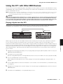
Playing a Synth from the CP1 . . . . . . . . . . . . . . . . . . . . . . . . . . . . . . . . . . . . . . . . . . . . . . . . 35
Using the CP1 with a Computer . . . . . . . . . . . . . . . . . . . . . . . . . . . . . . . . . . . . . . . . . . . . . . . 36
Connecting via USB . . . . . . . . . . . . . . . . . . . . . . . . . . . . . . . . . . . . . . . . . . . . . . . . . . . . . . . 36
Activating and Deactivating Local Control . . . . . . . . . . . . . . . . . . . . . . . . . . . . . . . . . . . . . . 38
8
CP1 Owner’s Manual
Storing Settings . . . . . . . . . . . . . . . . . . . . . . . . . . . . . . . . . . . . . . . . . . . . . . . . . . . . . . . . . . . . 39
Memory Structure . . . . . . . . . . . . . . . . . . . . . . . . . . . . . . . . . . . . . . . . . . . . . . . . . . . . . . . . . 39
Storing Settings . . . . . . . . . . . . . . . . . . . . . . . . . . . . . . . . . . . . . . . . . . . . . . . . . . . . . . . . . . . 40
Exchanging Files with USB Flash-Memory Devices . . . . . . . . . . . . . . . . . . . . . . . . . . . . . . . 41
Restoring Initial Settings . . . . . . . . . . . . . . . . . . . . . . . . . . . . . . . . . . . . . . . . . . . . . . . . . . . . . 42
Reference
43
Piano . . . . . . . . . . . . . . . . . . . . . . . . . . . . . . . . . . . . . . . . . . . . . . . . . . . . . . . . . . . . . . . . . . . . . 43
Piano Types & Pre-amplifiers . . . . . . . . . . . . . . . . . . . . . . . . . . . . . . . . . . . . . . . . . . . . . . . . 43
Parameters from the Piano Type Unit . . . . . . . . . . . . . . . . . . . . . . . . . . . . . . . . . . . . . . . . . 44
Parameters from the Pre-Amplifier Unit . . . . . . . . . . . . . . . . . . . . . . . . . . . . . . . . . . . . . . . . 45
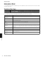
Modulation Effect . . . . . . . . . . . . . . . . . . . . . . . . . . . . . . . . . . . . . . . . . . . . . . . . . . . . . . . . . . . 46
Modulation Effect Types . . . . . . . . . . . . . . . . . . . . . . . . . . . . . . . . . . . . . . . . . . . . . . . . . . . . 46
Parameters from the Modulation Effect Block . . . . . . . . . . . . . . . . . . . . . . . . . . . . . . . . . . . . 47
Power-Amplifier / Compressor . . . . . . . . . . . . . . . . . . . . . . . . . . . . . . . . . . . . . . . . . . . . . . . . 48
Power-Amplifier / Compressor Types . . . . . . . . . . . . . . . . . . . . . . . . . . . . . . . . . . . . . . . . . . 48
Parameters from the Power-Amplifier / Compressor Block. . . . . . . . . . . . . . . . . . . . . . . . . . 49
Reverb . . . . . . . . . . . . . . . . . . . . . . . . . . . . . . . . . . . . . . . . . . . . . . . . . . . . . . . . . . . . . . . . . . . . 50
Common Settings . . . . . . . . . . . . . . . . . . . . . . . . . . . . . . . . . . . . . . . . . . . . . . . . . . . . . . . . . . . 51
First page: Performance name and keyboard playing mode . . . . . . . . . . . . . . . . . . . . . . . . 51
Second page: Pitch and pan for each part. . . . . . . . . . . . . . . . . . . . . . . . . . . . . . . . . . . . . . 53
Third page: Pitch bend and velocity for each part . . . . . . . . . . . . . . . . . . . . . . . . . . . . . . . . 53
Fourth page: Controller settings . . . . . . . . . . . . . . . . . . . . . . . . . . . . . . . . . . . . . . . . . . . . . . 54
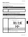
Master Equalizer . . . . . . . . . . . . . . . . . . . . . . . . . . . . . . . . . . . . . . . . . . . . . . . . . . . . . . . . . . . . 55
First page: Master Equalizer gain . . . . . . . . . . . . . . . . . . . . . . . . . . . . . . . . . . . . . . . . . . . . . 55
Second to sixth pages: Detailed settings for each band . . . . . . . . . . . . . . . . . . . . . . . . . . . 55
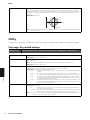
Utility . . . . . . . . . . . . . . . . . . . . . . . . . . . . . . . . . . . . . . . . . . . . . . . . . . . . . . . . . . . . . . . . . . . . . 56
First page: Key-related settings . . . . . . . . . . . . . . . . . . . . . . . . . . . . . . . . . . . . . . . . . . . . . . 56
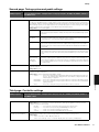
Second page: Tuning system and pedal settings . . . . . . . . . . . . . . . . . . . . . . . . . . . . . . . . 57
Third page: Controller settings . . . . . . . . . . . . . . . . . . . . . . . . . . . . . . . . . . . . . . . . . . . . . . . 57
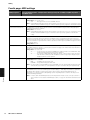
Fourth page: MIDI settings . . . . . . . . . . . . . . . . . . . . . . . . . . . . . . . . . . . . . . . . . . . . . . . . . . 58
Fifth page: Other settings . . . . . . . . . . . . . . . . . . . . . . . . . . . . . . . . . . . . . . . . . . . . . . . . . . . 59
File . . . . . . . . . . . . . . . . . . . . . . . . . . . . . . . . . . . . . . . . . . . . . . . . . . . . . . . . . . . . . . . . . . . . . . . 60
First page: Confirming contents of USB flash-memory device . . . . . . . . . . . . . . . . . . . . . . . 60
Second page: Saving files on a USB flash-memory device . . . . . . . . . . . . . . . . . . . . . . . . . 60
Third page: Loading files from a USB flash-memory device . . . . . . . . . . . . . . . . . . . . . . . . 61
Fourth page: Renaming files and directories . . . . . . . . . . . . . . . . . . . . . . . . . . . . . . . . . . . . 61
Fifth page: Deleting files and directories . . . . . . . . . . . . . . . . . . . . . . . . . . . . . . . . . . . . . . . 62
Sixth page: Creating directories . . . . . . . . . . . . . . . . . . . . . . . . . . . . . . . . . . . . . . . . . . . . . . 62
Seventh page: Formatting a USB flash-memory device . . . . . . . . . . . . . . . . . . . . . . . . . . . . 62
Appendix
63
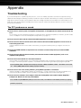
Troubleshooting . . . . . . . . . . . . . . . . . . . . . . . . . . . . . . . . . . . . . . . . . . . . . . . . . . . . . . . . . . . . 63
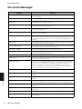
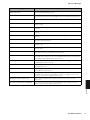
On-screen Messages . . . . . . . . . . . . . . . . . . . . . . . . . . . . . . . . . . . . . . . . . . . . . . . . . . . . . . . . 66
About the accessory disk . . . . . . . . . . . . . . . . . . . . . . . . . . . . . . . . . . . . . . . . . . . . . . . . . . . . 68
SOFTWARE LICENSE AGREEMENT. . . . . . . . . . . . . . . . . . . . . . . . . . . . . . . . . . . . . . . . . . . . 69
MIDI . . . . . . . . . . . . . . . . . . . . . . . . . . . . . . . . . . . . . . . . . . . . . . . . . . . . . . . . . . . . . . . . . . . . . . 71
Specifications . . . . . . . . . . . . . . . . . . . . . . . . . . . . . . . . . . . . . . . . . . . . . . . . . . . . . . . . . . . . . . 74
Index . . . . . . . . . . . . . . . . . . . . . . . . . . . . . . . . . . . . . . . . . . . . . . . . . . . . . . . . . . . . . . . . . . . . . 75
CP1 Owner’s Manual
9
Connecting the Power Cord
Setting Up
Setting Up
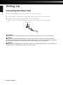
Connecting the Power Cord
1
Ensure that the [P] (power) switch on the rear panel is set to the OFF position.
2
Insert the appliance end of the power cord (included) into the [AC IN] socket, also on the rear panel.
3
Plug the other end of the power cord into a domestic-use, AC wall socket.
Make sure your CP1 meets the voltage requirement for the country or region in which it is being used.
[AC IN] socket
WARNING
Use only the AC power cord supplied with the CP1. The use of an inappropriate replacement can pose a fire and shock hazard!
CAUTION
Make sure your CP1 meets the voltage requirement for the country or region in which it is being used. The power cord includes a
grounding pin to prevent electrical shock and damage to equipment. When connecting to an outlet, connect the adaptor’s ground lead to
the ground screw. If you’re unsure how to connect, then contact your Yamaha dealer or service center (page 79).
CAUTION
Even when the switch is in the OFF position, a small amount of electricity is still flowing to the unit. When you are not using the CP1 for
a long time, make sure to unplug the AC power adaptor from the wall AC outlet.
10
CP1 Owner’s Manual
Connecting Audio Equipment
Connecting Audio Equipment
Setting Up
The CP1 does not come with built-in speakers. In order to hear what you play, therefore, you will need to connect it to a
stereo system or to an amplifier and speakers. You can also plug a set of headphones into the headphones jack in order
to monitor the sound directly. External audio equipment can be connected in a number of different ways as described
below. Based on the diagrams shown, choose the connection format most suited to your setup.
CAUTION
To prevent hearing loss, avoid using headphones at high volumes for extended periods of time.
CAUTION
Ensure that other equipment being used with the CP1 is not turned on until all necessary connections have been made.
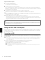
Monitoring with Amplifiers or Powered Speakers
A pair of keyboard amplifiers or powered speakers can be used to accurately reproduce the instrument’s rich sounds,
including pan and other widening effects. In this type of situation, connections to the amplifiers or speakers should be
made via the unbalanced [L/MONO] and [R] output jacks on the rear panel. If you would prefer to monitor your playing
using a single keyboard amplifier or powered speaker, the unbalanced [L/MONO] output jack should be used.
Powered speaker (left)
UNBALANCED [L/MONO] jack
Powered speaker (right)
BALANCED [R] jack
Headphones
CP1
Headphones jack
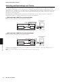
Listening via a Mixer
It is now commonplace for mixers to be connected to stage pianos used in recording and live performance
environments. In addition to the unbalanced jacks mentioned above, therefore, the CP1 also features a pair of
professional-use, balanced XLR connectors that prevent unwanted noise from entering signals. When connecting to a
mixer, we recommend that these balanced [L] and [R] output connectors be used.
OUTPUT L
OUTPUT R
Amplifier
BALANCED [L] jack
BALANCED [R] jack
Mixer
Headphones
Headphones jack
CP1
Speaker (left)
Speaker (right)
NOTE • The sound output via the headphones is identical to that output via the unbalanced [L/MONO] and [R] output jacks or the balanced [L] and [R]
output connectors. Furthermore, you can use the [MASTER VOLUME] dial on the CP1 control panel to adjust the volume of the external audio
equipment or headphones.
• Plugging in or disconnecting a set of headphones has no effect on the sound being output via the unbalanced [L/MONO] and [R] output jacks
and the balanced [L] and [R] output connectors.
CP1 Owner’s Manual
11
Connecting Pedals
Connecting Pedals
Setting Up
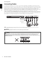
The pedal unit included with your CP1 is to be connected via the [SUSTAIN], [SOSTENUTO], and [SOFT] foot-switch
jacks located on the rear panel. The unit’s three plugs are color coded, with the light grey plug connected to the Sustain
pedal (located on the right), the dark grey plug connected to the Sostenuto pedal (located in the middle), and the black
plug connected to the Soft pedal (located on the left). Accordingly, the light grey plug should be plugged into the
[SUSTAIN] foot-switch jack, the dark grey plug should be plugged into the [SOSTENUTO] foot-switch jack, and the black
plug should be plugged into the [SOFT] foot-switch jack (each of which is also color coded in the same way).
In order to intuitively control a range of different CP1 parameters, furthermore, an optional FC4 or FC5 foot switch can
also be connected via the [ASSIGNABLE] foot-switch jack and optional FC7 or FC9 foot controllers can be connected via
the [1] and [2] foot-controller jacks. For details on how to assign parameters to these foot switches and controllers, see
the description concerning the fourth page of the Common Settings screen (on page 54 below).
Light grey plug
Dark grey plug
Black plug
NOTE The [SUSTAIN] foot-switch jack can also be used to connect an optional FC3, foot pedal or an optional FC4, or FC5 foot switch, while the
[SOSTENUTO] and [SOFT] foot-switch jacks can also be used to connect FC4 and FC5 foot switches.
CAUTION
When disconnecting the pedals from the CP1, be sure to pull the plugs and not the cables.
CAUTION
If the CP1 is setup on a flat surface such as a tabletop and the pedal plugs are oriented vertically downward as shown below after
being plugged in, the base of each will be placed under considerable strain due to lack of space, possibly leading to cable
breakage. In such a case, therefore, ensure that the plugs are tilted away from the vertical or take other suitable measures to avoid
placing them under strain.
12
CP1 Owner’s Manual
Turning on the CP1
Turning on the CP1
1
2
Press the [P] (power) switch on the stage piano’s rear panel.
3
Turn on any keyboard amplifiers or powered speakers connected to the CP1.
1
Setting Up
After you have made all of the required connections as described above, ensure that the [MASTER VOLUME] dial on
the left of the CP1 control panel and the volume of any connected keyboard amplifiers or powered speakers are fully
turned down (to MIN or 0), and also ensure that all equipment is turned off.
2
POWER
ON!
When turning off the stage piano, start by turning fully down the [MASTER VOLUME] dial on the control panel and the
volume of any connected keyboard amplifiers or powered speakers (to MIN or 0); then turn off the amplifiers or speakers;
and finally, press the [P] (power) switch on the rear panel.
TIP
If the CP1 is turned on with a USB flash-memory device already plugged in, it will either create an External Performance memory
on the device (see page 22) or read External Performance data already present on the device into the instrument’s DRAM (see
page 39) before displaying the main Performance screen. For more details, see page 19 from the section, Internal Design of the
CP1.
CP1 Owner’s Manual
13
Adjusting the Display Brightness
Adjusting the Display Brightness
Setting Up
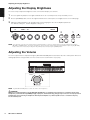
The correct way to adjust the brightness of the CP1’s built-in display is as follows.
1
Press the [UTILITY] button on the right-hand side of the CP1 control panel to call up the Utility screen.
2
Use the [PAGE R] button, also on the right-hand side of the control panel, to navigate to this screen’s fifth page.
3
Adjust the display brightness by turning Knob 1 and changing the value of the Brightns parameter.
The darkest setting is 1, and the brightest setting is 15.
Brightns
12
StartUP
PREA - 01
FctrySet5
[PUSH]
3
2
Knob 1
Knob 2
Knob 3
Knob 4
Knob 5
1
Knob 6
NOTE As an alternative to the above-described method, the display brightness can also be adjusted directly using the [UTILITY] button and the
[L PAGE] or [PAGE R] button. Specifically, the brightness can be reduced by holding down the [UTILITY] button and pressing the [L PAGE]
button, and it can be increased by holding down the [UTILITY] button and pressing the [PAGE R] button.
Adjusting the Volume
The CP1’s output volume is adjusted using the [MASTER VOLUME] dial located at the left of the control panel. Whenever
making adjustments using this dial, it is wise to listen to the actual volume as you play.
Quieter
Louder
NOTE The [MASTER VOLUME] dial also controls the volume of the headphones.
CAUTION
Whenever you make adjustments using the [MASTER VOLUME] dial, you simultaneously set the level of sound being output via the
headphones jack, the unbalanced [L/MONO] and [R] output jacks, and the balanced [L] and [R] output connectors. It is very important to
remember this fact if monitoring via headphones when keyboard amplifiers or powered speakers are also connected as they may
become extremely loud.
14
CP1 Owner’s Manual
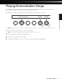
Playing Demonstration Songs
Your stage piano comes preloaded with a number of specially prepared demonstration songs. Follow the procedure
described below to play these songs using a range of different CP1 sounds.
1
Hold down the [UTILITY] button and press the [FILE] button to open the Demo Song screen.
DEMO>
Knob 2
Knob 3
Knob 4
Play
[PUSH]
Exit
[PUSH]
Knob 5
Knob 6
Playing Demonstration Songs
Knob 1
Song
01:Demo Song 1
NOTE This illustration of the Demo Song screen is provided for demonstration purposes only and may differ from that actually displayed on your
CP1.
2
Select the demo song you would like to listen to using Knob 2.
NOTE If a demo song is already playing, it must be stopped before a new one can be selected.
3
Press Knob 5 (Play) to start the selected demo song.
4
To stop the demo song, press Knob 5 (Stop).
5
To return to the Performance screen, you can press either Knob 6 (Exit) or the [EXIT] button.
CP1 Owner’s Manual
15
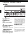
Top Surface
Component Names & Functions
Top Surface
!
3
4
5
6
7
8
9
@
Component Names & Functions
)
1
A-1
B-1
C0
D0
E0
F0
G0
A0
B0
C1
D1
E1
F1
G1
A1
B1
C2
D2
E2
F2
G2
A2
B2
C3
D3
E3
F3
2
1 Pitch bend wheel (see page 31)
Use this controller to shift the pitch of notes temporarily
upward or downward.
2 Headphones jack (see page 11)
Use this standard audio jack to connect a pair of stereo
headphones.
3 [MASTER VOLUME] dial (see page 14)
Use this dial to adjust the overall volume of the instrument.
4 [PIANO 1] and [PIANO 2] buttons (see page
43)
) [COMMON] button (see page 51)
5 [PRE-AMPLIFIER 1] and [PRE-AMPLIFIER 2]
buttons (see page 45)
By pressing this button and lighting it up, you can call up a
setting screen affecting both of the current Performance’s
parts.
6 [MODULATION EFFECT 1] and
[MODULATION EFFECT 2] buttons (see page
46)
! Display (see page 14)
7 [POWER-AMPLIFIER/COMPRESSOR 1] and
[POWER-AMPLIFIER/COMPRESSOR 2]
buttons (see page 48)
@ Knobs 1 to 6 (see page 28)
8 [REVERB] button (see page 50)
9 [MASTER EQUALIZER] button (see page 55)
By pressing the above buttons, you can turn on or off the
pianos, preamps, modulation effects, power amplifiers or
compressors, and reverb effect making up the current
16
Performance or the master equalizer for the instrument as a
whole (see page 19). When you do so, the button in question
will light up or go out accordingly. Furthermore, by pressing
and holding a button (for at least one second), you can call
up the corresponding setting screen, and the button will start
to flash. Even when a parameter setting screen has been
displayed in this way, the block can still be turned on or off
by pressing the corresponding button. It should be noted
that the button for the currently selected block will flash in
one of two different ways to indicate whether the block is on
or off; specifically, the button stays lit longer when the block
is on, and it stays off longer when the block is off.
CP1 Owner’s Manual
Using the display, you can confirm system messages, set
parameters, and perform a range of other tasks.
Numbered 1 through 6 from left to right, these knobs can be
turned to adjust the settings of the parameters assigned to
them. Within individual setting screens, furthermore, a
different set of parameters or tasks is assigned to the knobs,
and they can be turned or pressed to set the parameters or
execute the tasks.
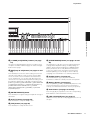
G
Top Surface
#
^&
(
A
B
$% *
G3
A3
B3
C4
D4
E4
F4
G4
A4
B4
C5
D5
E5
F5
G5
A5
B5
C6
D6
E6
F6
G6
A6
B6
Component Names & Functions
C
C7
# [L PAGE] and [PAGE R] buttons (see page
24)
* [STORE/ASSIGN] button (see pages 29 and
40)
Use these left and right buttons whenever a setting screen
comprises a number of different pages in order to navigate
between these pages.
Use this button to call up a screen for storing Performance
settings, Master Equalizer settings, or Utility settings. In
addition, by pressing and holding the [STORE/ASSIGN]
button (for at least one second) within the Performance
screen or a setting screen (for any block other than the
Master Equalizer), you can call up a screen for directly
assigning each of the Knobs 1 to 6 to block parameters.
$ [EXIT/jump to edit] button (see pages 26 and
33)
Press this button to leave the current setting screen for the
currently selected block or unit (see page 19), the Utility
screen, or the File screen and return to the Performance
screen. Furthermore, you can also jump directly from the
current screen to a specific block’s parameter setting screen
by holding the [EXIT/jump to edit] button and pressing the
[PIANO 1], [PIANO 2], [PRE-AMPLIFIER 1], [PRE-AMPLIFIER
2], [MODULATION EFFECT 1], [MODULATION EFFECT 2],
[POWER-AMPLIFIER/COMPRESSOR 1], [POWERAMPLIFIER/COMPRESSOR 2], [REVERB], or [MASTER
EQUALIZER] button.
( Number buttons (see page 27)
Use Number buttons [1] to [16] to select different
Performances within the currently-selected memory bank.
A Memory buttons (see page 27)
Press the [PRESET], [USER], or [EXTERNAL] button to select
the Preset Performance memory, the User Performance
memory, or an External Performance memory, respectively.
B Bank buttons (see pages 21 and 27)
% [ENTER/EXECUTE] button
Press the [A], [B], or [C] button to select the corresponding
bank within the current Performance memory.
Press this button to register settings and perform a range of
other tasks.
C [USB TO DEVICE] port (see page 23)
^ [UTILITY] button (see page 56)
USB flash-memory devices can be plugged into the CP1 via
this port.
Press this button to call up the Utility screen.
& [FILE] button (see page 60)
Press this button to call up the File screen.
CP1 Owner’s Manual
17
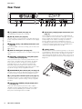
Rear Panel
Rear Panel
1
2
1 [P] (power) switch (see page 13)
Use this button to turn the CP1 on and off.
Component Names & Functions
2 [AC IN] socket (see page 10)
Use this socket to connect the power cord. Note that only the
power cord provided with the CP1 should be used to supply
power.
3 MIDI [IN], [OUT], and [THRU] connectors (see
page 35)
Use the three MIDI connectors to link up your CP1 with other
MIDI devices.
4 [USB TO HOST] port (see page 36)
Use this port to connect the CP1 to a computer using a USB
cable.
5 [SUSTAIN], [SOSTENUTO], and [SOFT] footswitch jacks (see page 30)
These jacks are used to connect the pedal unit that comes
with your CP1. An optional FC3, foot pedal or an optional
FC4, or FC5 foot switch can also be connected via the
[SUSTAIN] jack for use as a dedicated sustain pedal.
Meanwhile, optional FC4 and FC5 foot switches can be
connected via the [SOSTENUTO] and [SOFT] jacks in order
to perform a range of freely assignable functions.
6 [ASSIGNABLE] foot-switch jack (see page 12)
Use this jack to connect an optional FC4 or FC5 foot switch
in order to perform a range of freely assignable functions.
7 [1] and [2] foot-controller jacks (see page 12)
Use these two jacks to connect optional FC7 and FC9 foot
controllers in order to perform a range of freely assignable
functions.
8 Unbalanced [L/MONO] and [R] output jacks
(see page 11)
These two 1/4" mono phone jacks are used to output
unbalanced stereo signals. Alternatively, if mono output is
required, only the [L/MONO] jack should be connected.
Each jack’s nominal signal level is +4 dBu.
18
CP1 Owner’s Manual
3
4
5
6 7
8
9
9 Balanced [L] and [R] output connectors (see
page 11)
These XLR-type connectors are used to output balanced
stereo signals to mixers and the like. This type of connector
protects signals from interference and has an extremely
sturdy design. It also features a locking mechanism to
prevent cables from being accidentally disconnected.
Accordingly, the XLR connector is often used in professional
environments that demand a high level of reliability. Each
connector’s nominal signal level is +4 dBu.
) [LIGHT] switch
Use this switch to turn the Yamaha logo lamp on or off and to
set its brightness. When positioned fully to the left, the lamp
will be turned off; when moved to the right, the switch will
click and the lamp will light up. As the switch is then moved
further towards the right, it selects three increasing levels of
brightness.
)
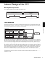
Principal Components
Internal Design of the CP1
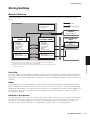
Principal Components
The CP1 primarily comprises a tone generator and a controller section.
Controller section
Keyboard
Input devices (i.e., knobs, pitch bend wheel, foot pedals, etc.)
Tone generator
Performance
MIDI output
MIDI input
USB, MIDI
USB, MIDI
Tone Generator
Internal Design of the CP1
The CP1’s tone generator produces sounds based on performance data that you create by playing the keyboard and
operating various controllers. The type of piano sound produced is defined by the currently selected Performance and
the Master Equalizer; meanwhile, each Performance comprises two individual piano parts together with a Reverb block.
The basic flow of signals between these components is illustrated below.
Performances
Part 1
Piano block
Piano Type
unit
Pre-Amplifier
unit
Modulation
Effect block
Power-Amplifier /
Compressor
block
Master Equalizer
block
Part 2
Piano block
Piano Type
unit
Pre-Amplifier
unit
Modulation
Effect block
Power-Amplifier /
Compressor
block
Reverb block
Each of the Parts in the Performance is subdivided into three distinct blocks — namely, the Piano block, the Modulation
Effect block, and the Power-Amplifier / Compressor block. These blocks allow the characteristics of acoustic pianos and
classic electric pianos to be faithfully reproduced by simulating a broad spectrum of piano types, amplifiers, effectors,
and other critical elements. Using the Piano Customize function to freely assemble these blocks, you can not only
replicate standard vintage settings, but you can also create unique hardware combinations that would never be possible
in the real world.
Each Performance allows the piano sounds produced by two different Parts to be sent through a common Reverb block
for finishing. Performances also contain a Common Settings area that allows a name, a keyboard mode, controllers, pan
settings, and a host of other parameters to be configured for each. These common settings can be used to make final
adjustments to the individual Performances that you create. Meanwhile, the CP1 is pre-loaded with an impressive
selection of Preset Performances, specially created by combining the above-described blocks to produce just the right
sound.
The Master Equalizer block mentioned above is used to set EQ parameters that affect all Performances. In this way, you
can adjust the tone of the CP1 to match the setup location so that it will always sound great, regardless of the
Performance selected.
CP1 Owner’s Manual
19
Tone Generator
Roles the Tone Generator’s Blocks & Parameters
The role of each of the blocks and the Common Settings area making up CP1 Performances are described below.
Piano Block
Each Piano block comprises two functional units — namely, the Piano Type unit and the Pre-Amplifier unit. The Piano
Type unit can accurately reproduce the unique sounds of many different acoustic pianos and classic electric pianos
using acoustic synthesis engines finely tuned for each; meanwhile, the Pre-Amplifier unit accurately recreates the
characteristics and nuances of the various types of preamps commonly used with each different piano type in actual live
settings. Whenever you choose an acoustic synthesis engine in the form of a Piano Type unit, the CP1 will automatically
select the best suited preamp for that type. In order to allow the sound to be further refined, a number of different
parameters can then be adjusted for the selected piano type and pre-amplifier. For details on piano types, preamp types,
and the corresponding parameters, see Piano from the Reference section (page 43).
Modulation Effect Block
Within each Modulation Effect block, you will find a versatile collection of modulation-type effects, which are
indispensable to piano sound design for stage and recording environments. Positioned immediately after the Piano block
for the corresponding Part, this block applies its modulation effect to the raw piano sound. A different type of modulation
effect can be selected for Part 1 and Part 2, and various parameters can be freely adjusted for each. For details on the
types of modulation effect available for use and the corresponding parameters, see Modulation Effect from the Reference
section (page 46).
Power-Amplifier / Compressor Block
Internal Design of the CP1
Capable of modeling a range of power amplifiers, speakers, and compressors with remarkable levels of precision, each
Power-Amplifier / Compressor block lets you select either a power-amplifier and speaker combination or a compressor
for use in shaping the piano sound of the corresponding Part. Positioned immediately after the Modulation Effect block,
this block further adjusts the overall tone. Furthermore, a different type of power-amplifier and speaker combination or
compressor can be selected for Part 1 and Part 2, and various parameters can be freely adjusted for each. For details on
the types of power amplifiers, speakers, and compressors available for use and the corresponding parameters, see
Power-Amplifier / Compressor from the Reference section (page 48).
Reverb Block
Within the Reverb block, you gain access to a variety of exquisite reverb algorithms originally developed by Yamaha for
use in pro-audio applications. This block allows a single reverb type to be selected for application to both Part 1 and Part
2, and each type features a number of freely configurable parameters. For details on the types of reverb effect available
for use and the corresponding parameters, see Reverb from the Reference section (page 50).
Common Settings Area
The Common Settings area is used to set a name, a keyboard mode, and controllers for each Performance, in addition to
pan, pitch, and velocity parameters for Part 1 and Part 2. If you wish to use your CP1 as a master keyboard capable of
controlling other MIDI devices, the relevant settings are made here. For details on the parameters set within the Common
Settings area, see Common Settings from the Reference section (page 51).
Master Equalizer Block
As the last step in sculpting the instrument’s sound, EQ settings made in the Master Equalizer block affect all
Performances. For details on the parameters that can be set within the Master Equalizer block, see Master Equalizer from
the Reference section (page 55).
20
CP1 Owner’s Manual
Tone Generator
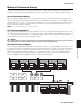
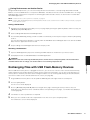
Makeup of Performance Memory
The CP1 can store Performances in three main memory areas — namely, the Preset Performance memory, the User
Performance memory, and an External Performance memory. The specific roles of each of these memory areas are
described below.
Preset Performance Memory
Accessed using the [PRESET] button, the Preset Performance memory is used to hold the Performance presets that
come ready-made with the CP1. Within this memory area, three individual memory banks — Preset A (PRE A), Preset B
(PRE B), and Preset C (PRE C) — each hold 16 Preset Performances. In order that they will always be available for use,
Preset Performances cannot be overwritten with other Performances that you have modified or created. As such, the
Preset Performance memory is read-only.
NOTE For a list of all Preset Performances, see the Data List booklet.
User Performance Memory
Accessed using the [USER] button, the User Performance memory is used to store original Performances that you have
created. Within this memory area, three individual memory banks — User A (USR A), User B (USR B), and User C (USR
C) — each hold 16 User Performances. In the instrument’s initial condition, the User Performance memory contains
exactly the same content as the Preset Performance memory.
CAUTION
If you overwrite a Performance in the User Performance memory, it will be permanently deleted. You should take special care, therefore,
when selecting where to store newly-created Performances in order to avoid loosing irreplaceable data.
External Performance Memory
Preset Performance memory
Internal Design of the CP1
Accessed using the [EXTERNAL] button, External Performance memories are stored on USB flash-memory devices. In
the same way as with the User Performance memory, each External Performance memory can be used to save original
Performances that you create. Within an External Performance memory, three individual memory banks — External A
(EXT A), External B (EXT B), and External C (EXT C) — each hold 16 Performances. Whenever a USB flash-memory
device containing an External Performance memory is plugged into the CP1, the entire memory is loaded into the
instrument’s DRAM so that its individual Performances may be played and edited.
User Performance memory
PRE A Bank
PRE B Bank
PRE C Bank
USR A Bank
USR B Bank
USR C Bank
Performances 1 to 16
Performances 1 to 16
Performances 1 to 16
Performances 1 to 16
Performances 1 to 16
Performances 1 to 16
Part 1
Part 1
Part 1
Part 1
Part 1
Part 1
Part 2
Part 2
Part 2
Part 2
Part 2
Part 2
External Performance memory
EXT A Bank
EXT B Bank
EXT C Bank
Performances 1 to 16
Performances 1 to 16
Performances 1 to 16
Part 1
Part 1
Part 1
Part 2
Part 2
Part 2
CP1 Owner’s Manual
21
Tone Generator
TIP
Using External Performance Memories
In order to store your Performance data in an External Performance memory or to use an External Performance memory already
saved on a USB flash-memory device, the USB flash-memory device in question must be plugged into the CP1. When you do so,
the instrument will behave in a number of different ways depending on whether or not it already contains an External Performance
memory and when it was last plugged in. Each of these actions is described below.
Root directory does not contain an External Performance memory:
As soon as you plug in a USB flash-memory device, the CP1 will check its root directory for an External Performance memory, and
none exists, it will create one in the form of a file named EXTBANK.C1E.
<<
<<
@@@@-----40%
Making external memory...
>>
>>
Root directory contains an External Performance memory:
If an External Performance memory already exists in the root directory of the USB flash-memory device, the action taken by the
CP1 will — as described below — depend on whether or not the device has already been plugged in and removed after turning
on the instrument.
• Not previously plugged in after turning on CP1:
When the USB flash-memory device in question is plugged in for the first time after turning on the CP1, data from its External
Performance memory will be automatically loaded into the instrument’s DRAM.
<<
<<
@@@@-----40%
Loading... (EXT performance)
>>
>>
Internal Design of the CP1
NOTE If a different USB flash-memory device has already been plugged in and removed after turning on the CP1, the instrument will operate in line
with the description from Previously plugged in after turning on CP1 below.
CAUTION
Whenever an External Performance memory from a USB flash-memory device is loaded into the CP1, all External Performance data
already contained within the instrument’s DRAM (see page 39) and any Performance currently within the Edit Buffer will be
overwritten. Before plugging in a USB flash-memory device, therefore, ensure that any important irreplaceable External
Performances contained within the internal DRAM or the Edit Buffer are stored.
• Previously plugged in after turning on CP1:
Whenever you plug in a USB flash-memory device that has already been plugged in and removed at least once after turning on
the CP1, you will be asked whether or not its External Performance memory should be loaded into the Edit Buffer. If the External
Performance memory loaded into the CP1 has been modified and contains irreplaceable Performances with unsaved
modifications, be sure to press Knob 5 (NO [PUSH]) at this time.
<<
<<
22
CP1 Owner’s Manual
Load?
(EXT perf)
YES
/
NO
[PUSH]
[PUSH]
>>
>>
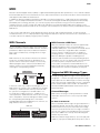
Controller Section
TIP
Plugging in a USB flash-memory device
Use the [USB TO DEVICE] port at the right end of the control panel for plugging in
USB flash-memory devices. Before plugging in a flash-memory device, ensure that
its connector matches the port and that both are oriented in the same direction.
NOTE Although the CP1’s connector is compatible with the USB 1.1 standard, you can
connect and use USB 2.0 flash-memory devices. In such a case, however, data will be
transferred at the USB 1.1 speed only.
Precautions when using [USB TO DEVICE] port
When plugging a USB flash-memory device into the CP1’s built-in [USB TO DEVICE] port, be sure to handle it with care and follow
the important precautions below.
NOTE For more details on how to use your USB flash-memory device, see the owner’s manual that came with it.
Supported USB memory devices
Only USB memory devices of the flash-memory variety can be used with the CP1. Furthermore, this instrument does not
necessarily support all commercially available USB flash-memory devices, and Yamaha cannot guarantee normal operation with
every such device on the market. Before purchasing a USB flash-memory device for use with the CP1, therefore, please visit the
following web page to confirm whether or not it is supported:
http://www.yamahasynth.com/
Working with USB flash-memory devices
With a USB flash-memory device plugged into the CP1, you can use it to save Performances that you have created and to load
previously-saved Performances back into the instrument.
Formatting a USB flash-memory device
Internal Design of the CP1
Certain types of USB flash-memory device must be formatted before they can be used with the CP1. Whenever you plug such a
device into the [USB TO DEVICE] port, a message prompting you to format it will be displayed on-screen. To do so, follow the
instructions presented on page 62.
CAUTION
When a USB flash-memory device is formatted, all data saved on it will be permanently erased. Before formatting a memory device,
therefore, ensure that it contains no irreplaceable data.
Write protection
Certain types of USB flash-memory device can be write-protected to prevent data from being accidentally erased. If your USB
memory contains irreplaceable data, we suggest that you use write protection to prevent accidental erasure. Meanwhile, if you
need to save data on a USB flash-memory device, be sure to disable write-protect.
Removing USB flash-memory devices
Before removing a USB flash-memory device from the [USB TO DEVICE] port, ensure that the CP1 is not currently accessing it in
order to save or load data.
CAUTION
Care should be taken to avoid plugging in and removing USB flash-memory devices with excessive frequency. If this precaution is
not observed, the CP1 may freeze and cease operating. In addition, a USB flash-memory device should never be removed before it
has been fully mounted or while it is being accessed by the CP1 in order to save or load data. Data on the flash-memory device or
on the instrument itself may be corrupted as a result of such action, and there is also a danger that the USB flash-memory device
could be permanently damaged.
Controller Section
The CP1 controller section consists of the keyboard, pitch bend wheel, knobs, foot pedals, and other input devices used
while playing. It is important to bear in mind that the keyboard itself does not generate any sound; instead, it sends note,
velocity, and other performance-related signals to the built-in tone generator section, which then produces sounds in
response. In the same way, the other devices in the controller section also send data to the tone generator whenever they
are operated or adjusted. Specifically speaking, the signals produced and sent by the keyboard and other controllers
are MIDI messages, and therefore, they can also be sent to other MIDI devices or a computer via the MIDI [OUT]
connector or [USB TO HOST] port.
CP1 Owner’s Manual
23
Basic CP1 Operations
Basic CP1 Operations
In this section, you will find a description both of the basic methods used to operate the CP1 and of the display content.
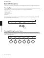
Changing Pages
The following screens presented on the CP1 display extend over a number of individual pages.
•
•
•
•
•
•
Performance screen
Common Settings screen
Zone Edit screen
Master Equalizer screen
Utility screen
File screen
Whenever one of these screens is called up, you can navigate between its pages using the [L PAGE] and [PAGE R]
buttons. Of the above-mentioned screens, furthermore, all but the Performance screen and the Zone Edit screen show
the current page number in the top-right corner.
Page number
Internal Design of the CP1
ONoteShf TNoteShf ODetune
0
0
0.0
TDetune
0.0
OPan
C
TPan
R 1
2
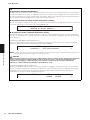
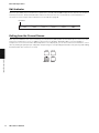
Changing & Setting Parameter Values
Each of the six knobs located below the CP1 display can be turned and pressed to change and set the parameters
assigned to them on the currently displayed screen. Specifically, a knob can be turned clockwise to increase a value and
counter-clockwise to decrease it.
EONoteShf TNoteShf ODetune
-24
+24
-12.7
Knob 1
24
CP1 Owner’s Manual
Knob 2
Knob 3
TDetune
+12.7
Knob 4
OPan
L63
TPan
R63
Knob 5
Knob 6
2
Basic CP1 Operations
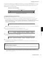
Setting Names
A name can be freely assigned to each Performance that you create or modify on the CP1 (see page 51). Furthermore, it
is also possible to specify names for files saved from the CP1 to a USB flash-memory device and for directories created
on these memory devices (see page 60). In order to do so, use the knob assigned to the Cursor parameter on the screen
in question to move the cursor within the name field, and then use the knob assigned to the Data parameter to change
the character at the cursor position.
E
Name
Cursor
[CF Grand]
Knob 1
Knob 2
Data
Knob 3
1
KbdMode
layer
Knob 4
Knob 5
Knob 6
Changes the character at the cursor position
Changes the cursor position
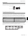
Entering Note Numbers
Internal Design of the CP1
While any parameter requiring a note to be set can be modified in the usual way by turning the assigned knob, you can
also select a note by pressing and holding that knob and playing the note on the keyboard.
Zone
Zone1
Knob 1
Note Limit
C 2 -- G 8
Knob 2
Knob 3
BankMSB-BankLSB
[on ] 0
0
Knob 4
Knob 5
PCNum R
[on ] 1
Knob 6
CP1 Owner’s Manual
25
Basic CP1 Operations
Edit Indicator
Whenever you modify any of a Performance’s parameters, the Edit Indicator (E) will appear at the top left of the display to
remind you to store it. Unsaved modifications will be lost whenever the CP1 is turned off or a new Performance is
selected. The correct way to store Performances is described on page 40.
Edit Indicator
EONoteShf TNoteShf ODetune
-24
+24
-12.7
TDetune
+12.7
OPan
L63
TPan
R63
2
Exiting from the Current Screen
Internal Design of the CP1
From any level within the CP1 screen hierarchy, you can press the [EXIT] button to move back up one screen level or to
return to the Performance screen. In addition, with a Piano, Pre-Amplifier, Modulation Effect, or Power-Amplifier /
Compressor screen or the Reverb or Master Equalizer screen displayed, you can also return to the Performance screen
either by holding the [EXIT/jump to edit] button and pressing the corresponding block button or by pressing and holding
that block button (for at least one second).
26
CP1 Owner’s Manual
Using CP1 Performances
Quick Start Guide
Using CP1 Performances
In terms of the CP1, each of the completed piano sounds available for playing via the keyboard is referred to as a
“Performance”, and these may be freely selected from the main Performance screen. Performances each comprise two
different piano parts — namely, Part 1 and Part 2 — and they can be either overlaid along the full length of the keyboard
or separated into two specific zones based on keyboard position or playing velocity.
Selecting a Performance
For demonstration purposes, we will now go step by step through the procedure of selecting a Performance for playing.
NOTE For details on the makeup of the memory areas used to store Performances, see Tone Generator from the section, Internal Design of the CP1
(page 19).
Number buttons
Memory buttons
Bank buttons
1
Within the Performance screen, use the [L PAGE] button to ensure that the first page (as shown below) is displayed.
(This screen extends across two different pages.)
Performance Screen (first page)
Quick Start Guide
Memory bank
Piano type selected for Part 1
Performance number
Piano type selected for Part 2
Performance name
PREA:01:[CF Grand ]
OBass
OMid
OTreble
O[CF 3Band] T[DXEP 2 ]
OHammer OKey-off ORevSend
Functions assigned to Knobs 1 to 6
NOTE The first page from the Performance screen indicates which Performance is selected, which types of piano it is constructed from, and which
parameters are assigned to Knobs 1 to 6; meanwhile, the second page illustrates the same parameters together with their current settings.
NOTE This illustration of the Performance screen is provided for demonstration purposes only and may differ from that actually displayed on your
CP1.
2
3
Press the [PRESET] button.
The area of the Performance memory for storing Preset Performances will be selected and the [PRESET] button will
start to flash. In addition, the Bank button and Number button for the currently selected Performance will also start to
flash.
Press the [A], [B], or [C] button.
The corresponding bank — Preset A (PRE A), Preset B (PRE B), or Preset C (PRE C) — will be selected.
CP1 Owner’s Manual
27
Using CP1 Performances
4
Press one of the Number buttons, [1] to [16].
With the Performance selection process now complete, the corresponding Memory, Bank, and Number buttons will
stop flashing and stay lit.
NOTE For a list of all Preset Performances, see the Data List booklet.
5
Use the keyboard to play the selected Performance.
TIP
The procedure for using an External Performance memory previously saved to a USB flash-memory device is as follows.
1
2
3
Ensure that the External Performance memory is located in the USB flash-memory device’s root directory.
Plug the USB flash-memory device into the CP1’s [USB TO DEVICE] port.
The data from the External Performance memory will be automatically loaded into the instrument. For more details, see Using
External Performance Memories from the section, Internal Design of the CP1 (page 22).
With the Performance screen displayed, press the [EXTERNAL] button and select a Performance.
To make a selection, follow the procedure described in Selecting a Performance above from Step 3.
Using Knobs 1 to 6 to Change the Sound
Function of Assignable Knobs
Quick Start Guide
Knobs 1 to 6 from the CP1 control panel can be assigned to various parameters from the individual blocks or units
making up each Performance. In specific terms, parameters from each Piano Type and Pre-Amplifier unit, from each
Modulation Effect and Power-Amplifier / Compressor block, and from the Reverb block can be freely assigned to these
knobs, and furthermore, each Performance can have a different set of assignments. You can confirm which parameters
are assigned to each knob on the Performance screen. Here, a number 1 or 2 may be shown at the left of parameter
names, and this indicates whether the parameter in question is from Part 1 or Part 2. For example, if a parameter
assignment were identified as being 1Decay, the corresponding knob would control the Decay parameter (i.e., decay
time) from Part 1. In cases where the assigned parameter affects both Part 1 and Part 2, no such number is displayed.
By turning Knobs 1 to 6, you can change the values set for the corresponding parameters in order to adjust the sound of
the currently selected Performance.
Performance screen (first page)
Piano type selected
for Part 1
Currently selected Performance
PREA:01:[CF Grand ]
OBass
OMid
OTreble
Piano type selected
for Part 2
O[CF 3Band] T[DXEP 2 ]
OHammer OKey-off ORevSend
Functions assigned to
Knobs 1 to 6
Part number
Knob 1
Knob 2
Knob 3
Knob 4
Knob 5
Knob 6
On the first page of the Performance screen, you can also press a knob to toggle on and off display of the current setting
value for its assigned parameter.
28
CP1 Owner’s Manual
Using CP1 Performances
To move from the first page to the second page of the Performance screen, press the [PAGE R] button. Here, you can
see both the names of the parameters assigned to each of the Knobs 1 to 6 and their current setting values, as shown
below. As such, the second page can be useful when editing a number of parameters together. You can press the
[L PAGE] button to return to the first page.
Performance Screen (second page)
Functions assigned to Knobs 1 to 6
OBass
+0.5dB
OMid
+0.0dB
OTreble
+1.0dB
OHammer
Normal
OKey-off ORevSend
+0
11
Current setting values for assigned parameters
Assigning Parameters to Knobs 1 to 6
Following the procedure described below, you can easily change parameter assignments for Knobs 1 to 6
1
With the Performance screen displayed, press and hold the [STORE/ASSIGN] button (for at least one second).
You will be asked to select the block or unit containing the parameter to be assigned, with available options
indicated by flashing buttons (i.e., [PIANO 1], [PIANO 2], [PRE-AMPLIFIER 1], [PRE-AMPLIFIER 2], [MODULATION
EFFECT 1], [MODULATION EFFECT 2], [POWER-AMPLIFIER/COMPRESSOR 1], [POWER-AMPLIFIER/
COMPRESSOR 2], and [REVERB]).
Select Piano/PreAmp/ModEffect/PowerAmp/Reverb SW!!
NOTE You can also select a block or unit directly from within its parameter setting page. To do so, press and hold the [STORE/ASSIGN] button (for
at least one second) and continue from Step 3 below.
2
Press one of the flashing buttons to select the required block or unit.
You will be asked to indicate which of the block’s parameters is to be assigned.
3
DampReso
Hammer
To select a parameter, press the corresponding knob.
You will now be asked to indicate the knob to which the selected parameter is to be assigned.
Select Assignable Knob!!
ODecay ORelease ODampRes
4
Key-off
Quick Start Guide
Select Parameter!!
Decay
Release
TDecay
TRelease TKey-off
Press the knob to be used to modify the selected parameter.
The display will return to the Performance screen, where you can confirm that the selected parameter is now
assigned to the required knob.
TIP
Removing Parameter Assignments
To remove a knob’s parameter assignment, navigate to page 2 of the Performance screen, press and hold the [EXIT] button, and
then press the knob in question. The parameter assignment will be canceled, and turning the knob will now have no effect on the
sound of the Performance.
NOTE When a new piano type, modulation effect, or power-amplifier / compressor is selected for either of the Performance’s parts within the
corresponding block or the reverb type is changed (see page 33), the set of parameters shaping the Performance’s sound will also change. If a
parameter assigned to one of the Knobs 1 to 6 is removed from the Performance in such a case, the knob in question will become unassigned and
labeled as *** on the Performance screen.
CP1 Owner’s Manual
29
Using CP1 Performances
Using Pedals
To use the pedal unit that came with your CP1, each of the three pedals should be connected via the rear panel’s
[SUSTAIN], [SOSTENUTO], and [SOFT] foot-switch jacks (see page 12).
Black plug
Light grey plug
Dark grey plug
Pedal unit
As described below, the way in which a pedal functions will depend on which of these jacks it is connected to.
[SUSTAIN] Foot-Switch Jack
The Sustain pedal, located at the right of the CP1 pedal unit, is connected to the [SUSTAIN] foot-switch jack via the light
grey plug. Notes played while this pedal is pressed will be sustained longer than normal after you release the
corresponding keys. This Sustain pedal also supports half-damper playing, with the degree to which the pedal is
pressed controlling how long the notes are sustained.
NOTE An optional FC3, foot pedal or an optional FC4, or FC5 foot switch can also be connected via the [SUSTAIN] foot-switch jack; however, only the
FC3 foot pedal supports half-damper playing. Whenever one of these optional pedals is to be used, the SusPedal parameter from the Utility screen
must be set accordingly (see page 57).
[SOSTENUTO] Foot-Switch Jack
Quick Start Guide
The Sostenuto pedal, located in the middle of the CP1 pedal unit, is connected to the [SOSTENUTO] foot-switch jack via
the dark grey plug. When you play a note or chord on the keyboard and press the sostenuto pedal while holding the
note(s), they will sustain as long as the pedal is held.
[SOFT] Foot-Switch Jack
The Soft pedal, located on the left of the CP1 pedal unit, is connected to the [SOFT] foot-switch jack via the black plug.
This pedal reduces the volume and slightly softens the timbre of notes played while it is pressed. The Soft pedal will not
affect notes that are already playing.
NOTE The function of the pedals connected via the [SOSTENUTO] and [SOFT] foot-switch jacks can be changed on the fourth page of the Common
Settings screen (see page 54).
NOTE Optional FC4 and FC5 foot switches can also be connected to the [SOSTENUTO] and [SOFT] foot-switch jacks.
30
CP1 Owner’s Manual
Using CP1 Performances
Bending Notes
Using the pitch bend wheel located at the left of the keyboard, you can bend the pitch of notes up and down as you play.
Notes are bent upward when you push the pitch bend wheel away from you and vice versa. This wheel is self-centering
and will, therefore, automatically return to the neutral position when released. Why not take a moment now to see how the
pitch bend wheel can change the sound of the notes you play.
Notes are bent upward
Notes are bent downward
Pitch bend wheel
Turning Performance Blocks On & Off
Once a Performance has been selected for playing, the various blocks and units from which it is constructed (see page
19) can be freely turned on and off by pressing the corresponding buttons. In specific terms, the blocks and units that
can be enabled and disabled in this way are Piano 1, Piano 2, Pre-Amplifier 1, Pre-Amplifier 2, Modulation Effect 1,
Modulation Effect 2, Power-Amplifier / Compressor 1, Power-Amplifier / Compressor 2, Reverb, and the Master Equalizer.
Whenever a block or unit is turned on or off, the corresponding button will light up or go out accordingly. It should be
noted, however, that the entire Part 1 or Part 2 will be turned on or off as a result of pressing the [PIANO 1] or [PIANO 2]
button, and whenever a [PRE-AMPLIFIER] button is pressed, the actual effect will depend on the corresponding piano
type (as shown below).
Effect of pressing [PRE-AMPLIFIER] button
71Rd I, 73Rd I, 75Rd I, 78Rd II, 69Wr, or 77Wr
The vibrato effect alone is turned on or off (i.e., tone control and
the Gain and Volume settings are unaffected).
CF 3Band, CF 2Band, S6 3Band, S6 2Band, DXEP 1, DXEP 2,
DXEP 3, or DXEP 4
All tone control functions are turned on or off. (The Gain and
Volume settings are unaffected).
Other than the above
Pre-amplifier functions are unaffected.
Quick Start Guide
Piano type
Furthermore, the Output parameter from each Power-Amplifier / Compressor block is unaffected by pressing of the
[POWER-AMPLIFIER/COMPRESSOR 1] or [POWER-AMPLIFIER/COMPRESSOR 2] button; specifically, this parameter
remains enabled even when all other parameters from the corresponding block are disabled.
To hear how the various blocks and units shape the sound, try turning them on and off as described above while playing
the CP1.
CP1 Owner’s Manual
31
Using CP1 Performances
TIP
Button Lighting Patterns
As shown below, the way in which the buttons for each of the elements making up a Performance (with the
exception of the Common Settings area) light up and turn off depends on the current CP1 setting condition. (The
buttons in question are [PIANO 1], [PIANO 2], [PRE-AMPLIFIER 1], [PRE-AMPLIFIER 2], [MODULATION EFFECT 1],
[MODULATION EFFECT 2], [POWER-AMPLIFIER/COMPRESSOR 1], [POWER-AMPLIFIER/COMPRESSOR 2],
[REVERB], and [MASTER EQUALIZER].)
• Not lit: The corresponding block or unit is turned off (i.e., deactivated).
• Lit: The corresponding block is turned on (i.e., activated).
• Flashing with longer lit period: The corresponding block or unit is turned on and its parameter setting screen is
being displayed.
• Flashing with shorter lit period: The corresponding block or unit is turned off, but its parameter setting screen is
being displayed.
NOTE With certain piano types, the corresponding Pre-Amplifier unit will continue to function even if its button is not lit or is flashing with a shorter
lit period. For details, see Turning Performance Blocks On & Off above.
NOTE The lighting behavior of the [COMMON] button differs from that of the block and unit buttons. Specifically, this button lights up when the
Quick Start Guide
Common Settings screen is displayed, and it remains off at all other times.
32
CP1 Owner’s Manual
Creating Original Performances
Creating Original Performances
Original piano sounds can be easily created on your CP1 by configuring the various blocks and units that make up
Performances and the Common Settings area. The following procedure can be applied to modify each of these
Performance elements while listening to how parameter changes actually affect the sound being produced. In specific
terms, the Piano, Modulation Effect, and Power-Amplifier / Compressor blocks are set for Part A and Part B; following this,
the Performance itself is completed by configuring the Reverb block and the Common Settings area; and finally, the
Master Equalizer is adjusted to match the overall sound of the CP1 to the setting in which it is being played.
NOTE For details on the individual blocks used to build Performances, see Tone Generator from the section, Internal Design of the CP1 (page 19).
1
Select the Performance that you would like to use as the start point for creating your own sound (see page 27).
CAUTION
If you wish to create your Performance within an External Performance memory, the USB flash-memory device containing the data for
that Performance memory must first be plugged into the CP1. Whenever a USB flash-memory device already containing an External
Performance memory is plugged into the CP1, that Performance memory will be automatically loaded. Furthermore, any Performances
contained within the CP1’s External Memory at that time will be overwritten.
2
Select a block or unit to configure by pressing and holding (for at least one second) the [PIANO 1], [PIANO 2], [PREAMPLIFIER 1], [PRE-AMPLIFIER 2], [MODULATION EFFECT 1], [MODULATION EFFECT 2], [POWER-AMPLIFIER/
COMPRESSOR 1], or [POWER-AMPLIFIER/COMPRESSOR 2] button.
The corresponding parameter setting screen will be displayed.
NOTE You can also call up a parameter setting screen by holding the [EXIT/jump to edit] button and pressing the corresponding block or unit
button.
3
E Piano
CF 3Band
Knob 1
4
5
6
Decay
+0
Knob 2
Release
+0
Knob 3
Key-off
+0
Knob 4
DampReso
+0
Hammer
Normal
Knob 5
Knob 6
Quick Start Guide
Turn Knob 1 to select a piano, modulation effect, or power-amplifier / compressor type (based on the block or unit
being edited). It should be noted that the preamp type is set automatically based on the type of piano selected.
Turn Knobs 2 to 6 (or Knobs 1 to 6 for a Pre-Amplifier unit) to set parameters as required.
For details on the parameters that can be set within each parameter setting screen, see the description of the
corresponding block from the Reference section (pages 44 through 49).
Repeat the above process from Step 2 for any other Piano, Modulation Effect, and Power-Amplifier / Compressor
blocks to be set. When all of the required settings have been made, proceed to the next step.
Press and hold the [REVERB] button (for at least one second).
The Reverb screen will be displayed.
NOTE You can jump to the Reverb screen by holding the [EXIT/jump to edit] button and pressing the [REVERB] button.
7
Turn Knob 1 to select the required type of reverb.
CP1 Owner’s Manual
33
Creating Original Performances
8
9
Turn Knobs 2 to 6 to set parameters as required.
For details on the parameters that can be set within this parameter setting screen, see Reverb from the Reference
section (page 50).
Press the [COMMON] button.
The Common Settings screen will be displayed.
10
Use the [L PAGE] and [PAGE R] buttons to navigate to the page containing the parameter(s) you wish to set.
Page number
EONoteShf TNoteShf ODetune
0
0
0.0
11
12
13
TDetune
0.0
OPan
C
TPan
R 1
2
Turn Knobs 1 to 6 to set parameters as required.
For details on the parameters set within the Common Settings area, see Common Settings from the Reference
section (page 51).
Repeat the above process from Step 10 for any other pages from the Master Equalizer screen containing
parameters that you wish to modify. When all of the required settings have been made, proceed to the next step.
Press the [STORE] button to store your Performance.
All parameters from the Piano blocks (i.e., the Piano Type and Pre-Amplifier units), the Modulation Effect blocks, the
Power-Amplifier / Compressor blocks, the Reverb block, and the Common Settings area are stored as a
Performance. For more details regarding the storing of Performances, see page 40.
Quick Start Guide
NOTE If you wish to save your Performance in an External Performance memory, be sure to plug the USB flash-memory device containing that
Performance memory into the [USB TO DEVICE] port before pressing the [STORE] button.
14
Press and hold the [MASTER EQUALIZER] button (for at least one second).
The Master Equalizer screen will be displayed.
NOTE You can jump to the Master Equalizer screen by holding the [EXIT/jump to edit] button and pressing the [MASTER EQUALIZER] button.
15
16
17
18
34
Use the [L PAGE] and [PAGE R] buttons to navigate to the page containing the parameter(s) you wish to set.
Turn Knobs 1 to 6 to set parameters as required.
For details on the parameters that can be set within the Master Equalizer block, see Master Equalizer from the
Reference section (page 55).
Repeat the above process from Step 15 for any other pages from the Master Equalizer screen containing
parameters that you wish to modify. When all of the required settings have been made, proceed to the next step.
Press the [STORE] button to store the modified Master Equalizer settings.
Master Equalizer settings are stored within the CP1’s system settings. For more details regarding the storing
procedure, see page 40.
CP1 Owner’s Manual
Using the CP1 with Other MIDI Devices
Using the CP1 with Other MIDI Devices
You can connect your CP1’s MIDI [IN], [OUT], and [THRU] connectors to MIDI connectors on other MIDI devices using
standard MIDI cables (sold separately). The following section will describe how MIDI devices connected in this way can
then be controlled from the CP1.
NOTE Even when the CP1 is connected to other MIDI devices, you will need to connect a stereo system or an amplifier and speakers in order to hear the
sound that it produces. Alternatively, a pair of headphones can always be connected for direct monitoring of the stage piano. For details, see
Connecting Audio Equipment from the section, Setting Up (page 11).
CAUTION
Ensure that other equipment being used with the CP1 is not turned on until all necessary connections have been made. With the volume
of all devices turned fully down, start by turning on devices that send MIDI data, then turn on those that receive MIDI data, and finally,
turn on any external audio equipment (with amplifiers or powered speakers being turned on last of all). Meanwhile, when shutting down
your system, start by turning the volume of all devices fully down, and then turn off devices in the reverse order to turning on.
Playing a Synth from the CP1
When the CP1 is connected to a MIDI instrument such as a synthesizer or tone-generator module and settings are
configured as described below, you can use the stage piano’s keyboard to play the other instrument.
MIDI OUT connector
CP1
MIDI IN connector
MIDI instrument such as a synthesizer or tonegenerator module
1
2
3
4
5
6
Quick Start Guide
With this type of connection, the same MIDI channel must be used by the CP1 and the other instrument to send and
receive, respectively. While the keyboard can be used in this type of situation to play CP1 sounds and the other
instrument’s sounds simultaneously, it is also possible to assign sounds to the keyboard in a number of different ways so
that they can each be played individually. The procedure for doing so is described below. If, however, you do not wish to
split up the keyboard in this way, you can instead navigate to the fourth page of the CP1’s Utility screen (see page 58)
after completing Steps 1 and 2 below and set the MIDI channel for transmission so as to match the other instrument’s
receive channel.
Navigate to the fourth page of the Utility screen (see page 58) by pressing the [UTILITY] button, and if necessary, the
[L PAGE] and [PAGE R] buttons.
Turn Knob 5 to set In/Out to “MIDI”.
With this setting, MIDI data will be exchanged with other devices via the CP1’s MIDI connectors (instead of via USB).
Press the [STORE] button to store this setting.
Utility settings are stored within the CP1’s system settings. For more details regarding the storing procedure, see
page 40.
Press the [EXIT] button to return to the Performance screen and then select the Performance you would like to play
(see page 27).
Navigate to the first page of the Common Settings screen by pressing the [COMMON] button, and if necessary, the
[L PAGE] button.
Turn Knob 5 to set KbdMode (i.e., the keyboard mode) to “zone”.
CP1 Owner’s Manual
35
Using the CP1 with a Computer
7
Press Knob 6 (ZoneEdit [PUSH]).
The Zone Edit screen will be displayed.
8
Turn Knob 1 and select the zone to be edited.
Zone 1 corresponds to Part 1, and Zone 2 corresponds to Part 2; meanwhile, Zones 3 and 4 are for playing other
MIDI devices. The MIDI channel for each zone is permanently set and cannot be changed. For details, see Zone Edit
from the Reference section (page 52).
9
Turn Knobs 2 to 6 to set parameters for the zone selected in the previous step.
For details on each of these parameters, see Zone Edit from the Reference section (page 52).
10
11
Use the [PAGE R] button to navigate to the second page of the Zone Edit screen, and then turn Knobs 2 to 6 to set
parameters for the zone selected in Step 8.
Setup the MIDI instrument to receive MIDI messages on channel 3 or 4.
This action matches the receive channel with the send channels for Zone 3 or Zone 4, which are used to play
external instruments. With this type of setup, you can play the CP1 and MIDI instrument at the same time using the
stage piano’s keyboard and have each of them produce different sounds.
TIP
The MIDI [THRU] connector is used to forward MIDI data received at the CP1’s MIDI [IN] connector, regardless of whether or not it
is also used within the instrument. When playing the CP1 from another MIDI device, therefore, the performance data can be output
from this MIDI [THRU] connector to also play other instruments.
Using the CP1 with a Computer
Quick Start Guide
The CP1 can also be connected to a computer in order to exchange MIDI data. For example, a sequencer running on a
computer could be used to play the stage piano, or you could send MIDI data created by playing the CP1 keyboard to
the computer for processing.
Connecting via USB
The following procedure describes how to connect the [USB TO HOST] port on the rear of the CP1 to a USB port on your
computer using a USB cable. When connected in this way, the CP1 and computer can exchange MIDI messages (but no
other types of data).
NOTE In order to enjoy the sounds produced by the CP1, you will need to connect it to a stereo system or to an amplifier and speakers. Alternatively, a
pair of headphones can always be connected for direct monitoring of the stage piano. For details, see Connecting Audio Equipment from the
section, Setting Up (page 11).
1
Using your computer, download the Yamaha USB-MIDI driver from the following website.
After you click Download, select a convenient location for the installation file.
http://www.global.yamaha.com/download/usb_midi/
NOTE Information on system requirements can also be found on the above website.
NOTE The USB-MIDI driver may be revised and updated without prior notice. Make sure to check the above website for the latest version and
related information.
36
CP1 Owner’s Manual
Using the CP1 with a Computer
2
Install the USB MIDI driver on your computer.
For instructions on installing, see the Installation Guide included in the downloaded file package.
When asked to connect the [USB TO HOST] port on your instrument (i.e., the CP1) to the computer using a USB
cable, do so as shown below.
USB cable
USB TO HOST
connector
CP1
3
USB connector
Computer
Setup the CP1 to allow MIDI data to be exchanged via the [USB TO HOST] port.
Navigate to the fourth page of the Utility screen (see page 58) by pressing the [UTILITY] button, and if necessary, the
[L PAGE] and [PAGE R] buttons. Then, turn Knob 5 to set In/Out to “USB MIDI”.
NOTE If you wish to connect your CP1 to a computer via MIDI cables, the In/Out parameter should be set to “MIDI”.
4
Press the [STORE] button to store this setting.
Utility settings are stored within the CP1’s system settings. For more details regarding the storing procedure, see
page 40.
Precautions when using the [USB TO HOST] port
Quick Start Guide
When connecting the CP1 to a computer via the [USB TO HOST] port, be sure to observe the following precautions. Failing to do
so risks freezing either or both of the devices and corrupting or losing data. If your CP1 or computer should freeze, restart the
application being used, reboot the computer, or turn the stage piano off once and then back on.
• Use a USB A-B cable.
• Before connecting to a computer via the [USB TO HOST] port, restore it from any power-saving mode (such as Suspend, Sleep,
or Standby).
• Connect the computer via the [USB TO HOST] port before turning on the CP1.
• Be sure to always perform the following steps before turning the CP1 on or off and either plugging or unplugging the USB cable.
- Quit all applications.
- Ensure that no data is being sent from the CP1. (Data is transmitted by playing the keyboard.)
• When connected to a computer, allow at least 6 seconds to pass between turning the CP1 on and off and plugging or
unplugging the USB cable.
TIP
Selecting Performances from a Computer via MIDI
Performances on your CP1 can be selected by sending MIDI messages from an application running on a connected computer. In
specific terms, the following three MIDI messages must be sent to your stage piano in order to successfully change
Performances.
• Bank select MSB
• Bank select LSB
• Program change
See the MIDI Data Table contained within the Data List booklet for details regarding the bank select MSB, bank select LSB, and
program change values assigned to each Performance.
CP1 Owner’s Manual
37
Using the CP1 with a Computer
Activating and Deactivating Local Control
Normally, when playing the CP1 in order to record its MIDI messages on a computer, those messages are sent directly to
the computer, and from there, they are returned to the instrument in order to play the built-in tone generator. If local
control of the CP1 is turned on (i.e., activated) at this time, the data produced by playing the keyboard will also be sent
directly to the tone generator, and as a result, the direct and returned messages will overlap, causing each note to be
played twice in quick succession.
Most applications allow MIDI Thru to be turned on or off, and therefore, you can setup your system in either of the
following ways to play or record in comfort without each note being heard twice.
With application’s MIDI Thru function activated:
In this case, local control of the CP1 should be deactivated.
Application running
on computer
USB ports
CP1
IN
OUT
OUT
Tone generator
Keyboard
Local control = Off
IN
MIDI Thru = On
Local from fourth page of Utility screen set to “off”
With application’s MIDI Thru function deactivated:
In this case, local control of the CP1 should be activated.
Application running
on computer
CP1
USB ports
OUT
IN
Keyboard
Tone generator
Quick Start Guide
Local control = On
Local from fourth page of Utility screen set to “on”
MIDI Thru = Off
*: MIDI Thru is a function that relays MIDI messages received at a MIDI IN connector directly to a MIDI OUT connector. With certain applications, this
function is also known as MIDI Echo.
NOTE For more details on MIDI Thru, see the User’s Manual that came with your computer application.
38
CP1 Owner’s Manual
Storing Settings
Storing Settings
Memory Structure
The following diagram shows the structure of the CP1’s internal memory and how data is exchanged with external
devices.
Internal Memory
Internal communication
Preset Data (ROM)
Preset Performance
Demo Songs
Edit Buffer
(DRAM)
Sequence application
User Memory
(flash ROM or DRAM)*2
Load
Store
Load
Store
Performances*3
Piano Type
Pre-Amplifier
Modulation Effect
Power-Amplifier /
Compressor
Reverb
Common Settings
System settings
Utility settings
Master Equalizer settings
USB Flash-Memory
Device
File loading and saving
System settings
Utility settings
Master Equalizer settings
MIDI instrument or
computer
Bulk Dump
*1
Performances
Piano Type
Pre-Amplifier
Modulation Effect
Power-Amplifier /
Compressor
Reverb
Common Settings
Communication between CP1 and
external device
External Performance
memory
“EXTBANK.C1E”
File extension: .C1A
Quick Start Guide
*1: The Bulk Dump function can be used only with data currently being edited in the Edit Buffer.
*2: User Performance memory banks reside in the instrument’s flash ROM, while External
Performance memories are loaded into the internal DRAM.
*3: Both User Performance memories and External Performance memories are displayed here in
the form of a single block.
Flash ROM
As its name suggests, Read Only Memory (ROM) is a type of memory designed specifically for reading of data, and as
such, data cannot normally be written to it. Flash ROM differs from the conventional type in that it can be overwritten —
allowing you to store your own original data. Furthermore, the content of flash ROM is maintained even when the power is
turned off.
DRAM
The term Random Access Memory (RAM) is used to describe memory designed for both reading and writing of data.
RAM is categorized into two different types based on the way in which content is stored — namely, static RAM (SRAM)
and dynamic RAM (DRAM). It is the latter type that is used for your CP1’s Edit Buffer. As the data stored in DRAM is lost
when the power is turned off, any important content should be transferred to flash ROM (i.e., the User Performance
memory) before doing so.
Edit Buffer & User Memory
The name Edit Buffer is given to an area of memory used to edit a single Performance or system settings. As this memory
area is non-permanent, its content must be stored in User Memory if it is to be reused. Furthermore, whenever a new
Performance is selected and edited, the entire content of the Edit Buffer will be overwritten with the new data. It is
important, therefore, that any Performance in the Edit Buffer is stored as soon as you are happy with it.
CP1 Owner’s Manual
39
Storing Settings
Storing Settings
When you have finished editing a Performance, you can either store it within the CP1’s User Performance memory or
save it in an External Performance memory. Master Equalizer and Utility settings, on the other hand, are stored in User
Memory as part of the instrument’s system settings. Furthermore, the Bulk Dump function can be used to transfer the
Performance currently being edited in the Edit Buffer to a connected MIDI device or DAW application for saving.
NOTE The Common Settings screen can be used to change the name of the Performance currently being edited. For details, see page 51 from the
Reference section.
CAUTION
Whenever you store a Performance within a Performance memory, the content at the selected location will be overwritten. It is wise,
therefore, to regularly create backup copies of important Performances on a USB flash-memory device or the like.
Storing Performances
NOTE If you wish to save Performances within an External Performance memory on a USB flash-memory device, ensure that it is plugged into the CP1 in
advance.
1
When you are happy with the Performance being edited, press the [STORE] button.
The Store screen will be displayed.
Store>
2
3
Quick Start Guide
4
[CF Grand
]>[CP1 Normal]
Memory
USRA
Number
01
Turn Knobs 5 and 6 to specify a location for storing the Performance in the form of a memory bank and number.
Before selecting an External Performance memory, ensure that the corresponding USB flash-memory device is
plugged into the instrument.
Press the [ENTER] button to confirm your selection.
You will be asked to confirm that you wish to proceed.
Press Knob 4 (YES [PUSH]) to do so.
When the Performance has been stored, the message “Completed.” will be displayed, followed by the Performance
screen for the stored Performance.
If you do not wish to proceed, press either Knob 5 (NO [PUSH]) or the [EXIT] button when the confirmation screen
from Step 3 is displayed.
CAUTION
The CP1 should never be turned off while the message “Executing...” is displayed on-screen. If this precaution is not observed, the
Performance may not be stored and the corresponding data may be permanently lost.
Storing Master Equalizer and Utility Settings
1
To save modified Master Equalizer or Utility settings, press the [STORE] button.
You will be asked to confirm that you wish to proceed.
<<
<<
2
Store MEQ & Utility?
YES
/
NO
[PUSH]
[PUSH]
>>
>>
Press Knob 4 (YES [PUSH]) to do so.
When the settings have been stored, the message “Completed.” will be displayed, followed by the Master Equalizer
or Utility screen.
If you do not wish to proceed, press either Knob 5 (NO [PUSH]) or the [EXIT] button when the confirmation screen
from Step 1 is displayed.
CAUTION
The CP1 should never be turned off while the message “Executing...” is displayed on-screen. If this precaution is not observed, the
settings may not be stored and the corresponding data may be permanently lost.
40
CP1 Owner’s Manual
Exchanging Files with USB Flash-Memory Devices
Saving Performances on Another Device
Using the Bulk Dump function, you can conveniently transfer the Performance currently being edited within the Edit
Buffer to a connected MIDI device or computer as MIDI data. This data can then be saved on the MIDI device or using a
DAW application running on the computer. The following procedure describes how to use this function in combination
with a DAW application.
NOTE For details on how to connect your CP1 to a computer, see page 36.
NOTE In order to utilize the Bulk Dump function, the DevNo parameter must be used to set the CP1’s device number correctly. For details, see page 58
from the Reference section.
Saving a Performance
1
2
3
4
Navigate to the fourth page of the Utility screen (see page 58) by pressing the [UTILITY] button, and if necessary, the
[L PAGE] and [PAGE R] buttons.
Start recording MIDI data with the DAW application.
Press Knob 6 (BulkDump [PUSH]), and when asked to confirm that you wish to proceed, press Knob 4 (YES [PUSH])
to do so.
The CP1 will transmit the Performance currently within the Edit Buffer to the DAW application in the form of raw MIDI
data, which the application will then record.
Stop recording on the DAW application and save the project file.
Restoring a Performance
1
Open the DAW-application project file containing the MIDI data for the Performance you wish to restore.
2
Start playback of the recorded MIDI data on the DAW application.
CAUTION
When the CP1 receives data saved using the Bulk Dump function, the Performance currently being edited on the instrument will be
overwritten with that data. Accordingly, care should be taken to avoid overwriting irreplaceable data.
Quick Start Guide
Exchanging Files with USB Flash-Memory Devices
When a USB flash-memory device is plugged into the CP1, you can use it to save the entire contents of User Memory
and to load previously-saved Performances back into the instrument. Furthermore, you can also create directories on
memory devices and carry out various other management tasks such as renaming and deleting. As described below,
each of these tasks can be carried out from the File screen (see page 60).
1
2
3
4
5
Plug a USB flash-memory device into the [USB TO DEVICE] port at the right end of the control panel.
Press the [FILE] button.
The File screen will be displayed.
Use the [L PAGE] and [PAGE R] buttons to navigate to the page containing the task you wish to carry out.
For details on the tasks that can be carried out and the corresponding screen pages, see File from the Reference
section (page 60).
Turn Knobs 1 to 6 to set parameters as required.
When you have carried out all of the required tasks in the File screen, press the [EXIT] button.
The Performance screen will be displayed.
CP1 Owner’s Manual
41
Restoring Initial Settings
Restoring Initial Settings
The following procedure describes how to use the Factory Set function to restore the User Memory to its initial condition.
CAUTION
Whenever the Factory Set function is used to restore initial settings, the current content of the User Performance memory and system
settings will be overwritten. Care should, therefore, be taken to avoid overwriting irreplaceable data. Furthermore, it is wise to regularly
create backup copies of system settings and important Performance data on a USB flash-memory device, computer, or the like.
1
2
3
Navigate to the fifth page of the Utility screen by pressing the [UTILITY] button, and if necessary, the [PAGE R]
button.
Press Knob 6 (FctrySet [PUSH]).
You will be asked to confirm that you wish to proceed.
Press Knob 4 (YES [PUSH]) to restore the CP1’s initial settings.
When the data has been restored, the message “Completed.” will be displayed, followed by the Utility screen.
If you do not wish to proceed, press either Knob 5 (NO [PUSH]) or the [EXIT] button when the confirmation screen
from Step 2 is displayed.
CAUTION
Quick Start Guide
The CP1 should never be turned off while the message “Executing...” is displayed on-screen. If this precaution is not observed, the
content of the User Memory may be lost and other system data may become corrupted, preventing the CP1 from operating normally the
next time it is turned on.
42
CP1 Owner’s Manual
Piano
Reference
This section provides a detailed description of the parameters used to configure the CP1.
Piano
Each of the Piano blocks allows a piano type and associated pre-amplifier to be selected for its respective part — that is,
Part 1 or Part 2.
Piano Types & Pre-amplifiers
Editing Sequence
Press and hold the [PIANO 1] or [PIANO 2] button (for at least one second) Turn Knob 1 (Piano)
The CP1’s Piano Type units are loaded with a rich collection of sounds making it possible to faithfully reproduce the sonic
characteristics of a broad spectrum of acoustic pianos and classic electric pianos. Furthermore, each of the piano types
modeled by this unit is associated with a specific preamp, which in turn is modeled by the Pre-amplifier unit. The
following table shows the different piano types that can be selected, the characteristics and features of each, and the
preamps with which they are associated.
Description
CF 3Band*
The CF 3Band piano has a straightforward sound, making it suitable for practically all musical genres. Featuring a broad dynamic
range, this piano type provides for highly expressive performances. The accompanying pre-amplifier supports control of tone in
three different bands and is specially tuned for the Yamaha CFIIIS Concert Grand Piano.
CF 2Band*
With its unassuming, candid sound, the CF 2Band can be widely used in practically any style of music, enhancing the
expressiveness of performances with its extensive dynamic range. Supporting two-band tone control, the accompanying preamplifier is specially tuned for the Yamaha CFIIIS Concert Grand Piano.
S6 3Band*
In contrast to the two CF-series pianos, the S6 3Band has a more compact, woody sound. Allowing you to play with both warmth
and power, it is ideal for a diverse range of musical genres. The accompanying pre-amplifier supports control of tone in three
different bands and is specially tuned for the Yamaha S6 Grand Piano.
S6 2Band*
The S6 2Band delivers a more compact, woody sound than the pianos of the CF series, and its combination of warmth and power
make this piano an excellent choice for many different types of music. Supporting two-band tone control, the accompanying preamplifier is specially tuned for the Yamaha S6 Grand Piano.
CP80*
Reproducing the classic sound of the Yamaha CP80 Electric Grand Piano, the CP80 piano type can also be used to recreate an
unique “Eighties” feel by boosting the high frequencies with the accompanying pre-amplifier.
CP88*
The CP88 piano and accompanying pre-amplifier deliver a nostalgia-laden sound distinctive of the Yamaha CP80 Electric Grand
Piano, particularly in the mid-frequency range.
71Rd I
The 71Rd I is the earliest-sounding of the CP1’s Rd-series electric pianos. With the soft attack and fast decay distinctive of felt
hammers, it produces a mellow, hollow tone.
73Rd I
The 73Rd I piano replicates an electric piano with rubber-topped hammers, and compared to the 71 Rd I, it has a slightly brighter,
more sustained tone. Overall, this Rd-series piano produces a dark, heavy sound.
75Rd I
The 75Rd I piano reproduces the bright, sustained sound of an electric piano featuring high-performance versions of tines,
pickups, and other sound-generating components.
78Rd II
Replicating the effect of plastic hammers and a high-fidelity, integrated-circuit pre-amplifier, the 78Rd II boasts the brightest sound
of the Rd series.
Dyno
The Dyno piano type significantly boosts the high-frequency range of the 78Rd II to give a sparkling “Eighties” sound.
69Wr
In contrast to the Rd piano types provided by the CP1, the 69Wr is characterized by a gentle attack and fast decay. Furthermore,
this piano type features a tight dynamic range.
77Wr
Rounding off the CP1’s vintage electric piano lineup, the 77Wr piano type features a stronger attack and more brilliant overall tone
than the 69Wr.
DXEP 1
Using the DXEP 1 piano type, you can reproduce FullTines — the classic electric-piano preset from the Yamaha DX7 II
synthesizer.
DXEP 2
As a variation on the DXEP1 piano type, DXEP 2 delivers a mellower electric piano sound.
DXEP 3
The DXEP 3 electric-piano sound is characterized its woody attack.
DXEP 4
In marked contrast to the CP1’s other DXEP sounds, DXEP 4 uses a strong attack to produce a wholly new type of DX electric
piano sound.
NOTE
Reference
Piano type
Piano types marked with an asterisk (*) can have their tuning adjusted by setting the TunCurve parameter (Piano Tuning Curve) to “stretch” (see
page 56).
CP1 Owner’s Manual
43
Piano
Parameters from the Piano Type Unit
Editing Sequence:
Press and hold the [PIANO 1] or [PIANO 2] button (for at least one second) Turn Knobs 2 to 6
Each of the different types of piano that your CP1 can replicate uses a different mechanism to realize its characteristic
sound, and for that reason, is configured using different parameters. In the following table, you will find a description of
all of the parameters used with different piano types.
NOTE
For more details on the specific parameters associated with each different type of piano, see the Piano block’s parameter list in the Data List
booklet.
On-screen name
(and full name)
Associated piano types
Description
Decay
(Decay Time)
All types
This parameter is used to adjust how fast a note decays while the key is
being held down.
Setting values: -16 to +16
Release
(Release Time)
All types
This parameter is used to adjust how fast a note decays after the
corresponding key is released.
Setting values: -16 to +16
Key-off
(Key-off Noise Level)
All except DXEP 1 to DXEP 4
This parameter is used to recreate the sound of dampers pressing
against the strings when you remove your fingers from the keyboard. In
specific terms, the Key-off parameter sets the volume of this key-off noise.
Setting values: -16 to +16
Rls Tone
(Release Tone)
DXEP 1 to DXEP 4
This parameter is used to adjust the tone of notes when you remove your
fingers from the keyboard.
Setting values: 0 to 16
DampReso
(Damper Resonance Level)
CF 3Band, CF 2Band, S6
3Band, S6 2Band
This parameter can be used in conjunction with a connected Sustain
pedal to recreate the sound of strings resonating in response to pressing
of an acoustic piano’s damper pedal. In specific terms, the DampReso
parameter sets the depth of this resonance
Setting values: -16 to +16
StrkPos
(Striking Position)
71Rd I, 73Rd II, 75Rd I,
78Rd II, Dyno, 69Wr, 77Wr
This parameter is used to replicate the effect of changing the position at
which the strings are struck by the hammers.
Setting values: Top3 to Top1, Default, or Rear1 to Rear3
AtkTimbr
(Attack Timbre)
DXEP 1 to DXEP 4
Hammer
(Hammer Stiffness)
All except DXEP 1 to DXEP 4
This parameter is used to adjust the tone of the attack portion of notes.
Setting values: Soft2, Soft1, Default, Hard1, or Hard2
This parameter is used to adjust the apparent softness or hardness of the
piano sound in much the same way as if softer or harder hammers were
used to strike the strings.
Setting values: Soft2, Soft1, Normal, Hard1, or Hard2
Reference
OscDetun
(Oscillator Detune)
44
CP1 Owner’s Manual
DXEP 1 to DXEP 4
This parameter is used to adjust the degree to which vibrato is applied.
Setting values: -16 to +16
Piano
Parameters from the Pre-Amplifier Unit
Editing Sequence:
Press and hold the [PRE-AMPLIFIER 1] or [PRE-AMPLIFIER 2] button (for at least one second)
Turn Knobs 1 to 6
Pre-amplifiers are set automatically based on the type of piano selected; however, the following parameters can be used
to modify the way in which each Pre-Amplifier unit affects the corresponding piano sound. Each different preamp type is
configured using a different set of parameters. In the following table, you will find a description of all such parameters in
alphabetic order.
Associated piano types
Description
Bass
CF 3Band, S6 3Band, CP80,
CP88, 71Rd I, 73Rd I, 75Rd I,
78Rd II, Dyno, 69Wr, 77Wr
This parameter is used to adjust the volume of the low-frequency component.
Brill.
(Brilliance)
CP80, CP88
This parameter is used to adjust the brightness of the sounds produced.
D
Depth
(Vibrato Depth)
71Rd I, 73Rd I, 75Rd I, 78Rd II,
69Wr, 77Wr
This parameter is used to adjust the depth of the pre-amplifier vibrato.
G
Gain
(Input Gain)
All types
This parameter is used to adjust the volume of the signal input into the pre-amplifier.
H
High
DXEP 1 to DXEP 4
This parameter is used to adjust the volume of the high-frequency component.
HighMid
(High Middle)
DXEP 1 to DXEP 4
This parameter is used to adjust the volume of the high mid-frequency component.
Low
DXEP 1 to DXEP 4
This parameter is used to adjust the volume of the low-frequency component.
LowMid
(Low Middle)
DXEP 1 to DXEP 4
This parameter is used to adjust the volume of the low mid-frequency component.
Mid
CF 3Band, S6 3Band
This parameter is used to adjust the volume of the mid-frequency component.
Middle
CP80, CP88
This parameter is used to adjust the volume of the mid-frequency component.
MidBoost
(Mid Boost)
69Wr, 77Wr
This parameter is used to adjust the volume of the mid-frequency component.
MidFreq
(Mid Frequency)
CF 3Band, S6 3Band
This parameter is used to adjust the frequency of the mid-frequency component.
N
Normal
Dyno
This parameter is used to adjust the volume of the mid-frequency component.
O
Overtone
Dyno
This parameter is used to adjust the volume of the high-frequency component.
P
Pk1Freq
(Peak1 Frequency)
CF 2Band, S6 2Band
This parameter is used to adjust the central frequency of Peak1 (i.e., Peaking Filter
1).
Pk1Gain
(Peak1 Gain)
CF 2Band, S6 2Band
This parameter is used to adjust the volume of Peak1 (i.e., Peaking Filter 1).
Pk2Freq
(Peak2 Frequency)
CF 2Band, S6 2Band
This parameter is used to adjust the central frequency of Peak2 (i.e., Peaking Filter
2).
Pk2Gain
(Peak2 Gain)
CF 2Band, S6 2Band
This parameter is used to adjust the volume of Peak2 (i.e., Peaking Filter 2).
S
Speed
(Vibrato Speed)
71Rd I, 73Rd I, 75Rd I, 78Rd II
This parameter is used to adjust the speed of the pre-amplifier vibrato.
T
Treble
CF 3Band, S6 3Band, CP80,
CP88, 71Rd I, 73Rd I, 75Rd I,
78Rd II, 69Wr, 77Wr
This parameter is used to adjust the volume of the high-frequency component.
V
Volume
All types
This parameter is used to adjust the output volume. If set to 100 or greater when
71Rd I, 73Rd I, 75Rd I, 78Rd II, 69Wr, or 77Wr has been set as the part’s piano
type, drive will also be added to the sound.
B
L
M
NOTE
Reference
On-screen name
(and full name)
Output from a pre-amplifier will be muted briefly whenever one of the following tone-control parameters is modified.
• CP80 or CP88 pre-amplifier: Bass, Middle, Treble, or Brill
• 71Rd I, 73Rd I, or 75Rd I pre-amplifier: Bass
• 78Rd II pre-amplifier: Treble
• Dyno pre-amplifier: Bass or Overtone
CP1 Owner’s Manual
45
Modulation Effect
Modulation Effect
In each Modulation Effect block, a modulation-type effect is applied to the piano sound of either Part 1 or Part 2 to modify
its spatial characteristics.
Modulation Effect Types
Editing Sequence:
Press and hold the [MODULATION EFFECT 1] or [MODULATION EFFECT 2] button (for at least one second)
Turn Knob 1 (MdEffect)
The following table identifies and describes the different types of effect that can be selected in each Modulation Effect
block. A different type of effect can be applied to the piano sound of each of Part 1 and Part 2.
Description
SmallPha
(Small Phaser)
Small Phaser operates like a vintage phaser, applying a unique sweeping effect.
Max90
Max90 emulates a vintage phaser, producing a more traditional-sounding effect.
Max100
Another vintage-type phaser, the Max100 effect can modify the sound in a number of different ways based
on its Mode parameter setting.
Flanger
The Flanger effect reproduces the sound of a vintage flanger.
TouchWah
(Touch Wah)
Touch Wah produces a classic filter-sweep effect in response to how hard or soft the keyboard is played.
PedalWah
(Pedal Wah)
Another classic filter-sweep effect, Pedal Wah is operated using a pedal or another controller. In order to
use this effect, it is necessary to specify which controller is to be used, and this can be done by selecting
the controller on the fourth page of the Common Settings screen (see page 54) and setting “MdEffect” as its
destination.
Chorus
The Chorus effect applies a standard chorus.
D Chorus
D Chorus produces a chorus effect that is more natural sounding, softer, and wider.
816Cho
(816Chorus)
The 816Chorus effect reproduces the thick, detuned chorus of the TX816 — famous for combining eight
DX7s in a single rack unit.
Sympho
(Symphonic)
Symphonic uses multi-stage modulation to produce a wider-sounding chorus.
Reference
Effect type
46
CP1 Owner’s Manual
Modulation Effect
Parameters from the Modulation Effect Block
Editing Sequence:
Press and hold the [MODULATION EFFECT 1] or [MODULATION EFFECT 2] button (for at least one second)
Turn Knobs 2 to 6
Each type of modulation effect is configured using a different set of parameters, which adjust the sound of the effect in
various ways. In the following table, you will find a description of all such parameters in alphabetic order.
NOTE
For more details on the specific parameters associated with each different type of modulation effect, see the Modulation Effect block’s parameter
list in the Data List booklet.
On-screen name
(and full name)
Associated effect types
Description
B
Bottom
Touch Wah and Pedal Wah
This parameter is used to set the lowest point in the filter’s sweep range.
C
Color
SmallPha
This parameter is used to adjust the way in which the phaser sweeps.
D
Delay
Symphonic
This parameter is used to set the delay-time offset for modulation.
Depth
Flanger, Chorus, 816chorus,
and Symphonic
This parameter is used to set the degree to which modulation is applied.
Drive
SmallPha and Max90
This parameter is used to set the phaser’s input level.
Touch Wah and Pedal Wah
This parameter is used to adjust the way in which the sound distorts.
Feedback
Flanger and 816Chorus
This parameter is used adjust the degree to which output from the effect
is fed back into its input.
M
Manual
Flanger
This parameter is used to set the offset value for delay modulation.
Mix
Flanger, Chorus, 816Chorus
and Symphonic
This parameter is used to adjust the volume of the effect sound.
Mode
Max100
This parameter is used to select the phaser mode.
Pedal Control
Pedal Wah
This parameter is used to set the cutoff frequency for the wah filter.
Phase
816Chorus
This parameter is used to set the phase offset for the chorus effect.
Rate
SmallPha
This parameter is used to adjust the phaser speed.
Reso
(Resonance Offset)
Touch Wah and Pedal Wah
This parameter is used to set the resonance offset value.
Sens.
(Sensitivity)
Touch Wah
This parameter is used to adjust how sensitive the filter-sweep effect is to
key velocity.
Speed
Max90, Max100, Flanger,
Chorus, 816Chorus, and
Symphonic
This parameter is used to adjust the modulation speed.
Top
Touch Wah and Pedal Wah
This parameter is used to set the highest point in the filter’s sweep range.
Type
Max90
This parameter is used to select the phaser type.
D Chorus
This parameter is used to select the chorus type.
P
R
S
T
CP1 Owner’s Manual
Reference
F
47
Power-Amplifier / Compressor
Power-Amplifier / Compressor
Using a Power-Amplifier / Compressor block, you can adjust the piano sound of Part 1 or Part 2 either using faithful
reproductions of electric-piano power amps and speakers, or alternatively, using a compressor.
Power-Amplifier / Compressor Types
Editing Sequence:
Press and hold the [POWER AMPLIFIER/COMPRESSOR 1] or [POWER AMPLIFIER/COMPRESSOR 2] button
(for at least one second) Turn Knob 1 (PowerAmp)
The following table identifies the different power amplifier / compressor types provided by this block and provides a
description of each. A different power amplifier / compressor type can be applied to the sound from the Piano block and
Modulation Effect block of each of Part 1 and Part 2.
NOTE
If CF 3Band, CF 2Band, S6 3Band, or S6 2Band has been set as a part’s piano type, only Clean or Comp376 can be selected in the corresponding
Power-Amplifier / Compressor block.
Description
71Rd I
(PowerAmp 71Rd I)
PowerAmp 71Rd I adds a warm, vintage-type distortion to the sound. As such, it is ideal for enhancing the
acoustic nuances of electric pianos.
73Rd I
(PowerAmp 73Rd I)
Also intended for use with electric pianos, PowerAmp 73Rd I is a pleasant sounding power amplifier
producing a spacious, mellower tone.
75Rd I
(PowerAmp 75Rd I)
PowerAmp 75Rd I is an electric-piano power amplifier that energizes the piano sound to produce a
powerful, all-engulfing tone.
78Rd II
(PowerAmp 78Rd II)
Characterized by a clear, highly-present tone, the PowerAmp 78Rd II electric-piano power amplifier works
particularly well with chorus-type effects.
69Wr
(PowerAmp 69Wr)
Delivering both power and subtlety, PowerAmp 69Wr is an electric-piano power amplifier that enhances lowend punch while producing a richer overall sound.
77Wr
(PowerAmp 77Wr)
PowerAmp 77Wr adds a bright, colorful ambience to electric piano sounds in order to achieve a higher
degree of presence.
Clean
(Clean Amp)
Modeling an ideal power amplifier, Clean Amp boosts sounds evenly across the entire frequency spectrum.
Comp376
(Compressor 376)
Compressor 376 is a vintage-type compressor that can be used to control the dynamics of your piano
sounds.
Reference
Power amplifier /
compressor type
48
CP1 Owner’s Manual
Power-Amplifier / Compressor
Parameters from the Power-Amplifier / Compressor Block
Editing Sequence:
Press and hold the [POWER AMPLIFIER/COMPRESSOR 1] or [POWER AMPLIFIER/COMPRESSOR 2] button
(for at least one second) Turn Knobs 2 to 6
Each power-amplifier / compressor type is configured using a different set of parameters, which adjust the sound
produced by the block in various ways. In the following table, you will find a description of all such parameters in
alphabetic order.
NOTE
For more details on the specific parameters associated with each different power amplifier / compressor type, see the Power-Amplifier /
Compressor block’s parameter list in the Data List booklet.
On-screen name
(and full name)
Associated power amplifier /
compressor types
Description
A
Attack
Compressor 376
This parameter is used to set the amount of time that elapses
between playing a note and activation of the compressor.
D
Drive
PowerAmp 71Rd I, PowerAmp 73Rd I,
PowerAmp 75Rd I, PowerAmp 78Rd II,
PowerAmp 69Wr, and PowerAmp 77Wr
This parameter is used to adjust the way in which the sound
distorts. In order to produce an effect, the LineBal parameter’s
speaker output (S) must be raised by a certain amount. If the line
output (L) is maximized, Drive will have no effect.
Compressor 376
This parameter is used to adjust the degree to which
compression is applied.
L
LineBal
(Line Balance)
PowerAmp 71Rd I, PowerAmp 73Rd I,
PowerAmp 75Rd I, PowerAmp 78Rd II,
PowerAmp 69Wr, and PowerAmp 77Wr
This parameter is used to adjust the balance between the
speaker output (S) and line output (L).
O
Output
PowerAmp 71Rd I, PowerAmp 73Rd I,
PowerAmp 75Rd I, PowerAmp 78Rd II,
PowerAmp 69Wr, PowerAmp 77Wr,
Compressor 376, and Clean Amp
This parameter is used to set the output level.
Ratio
Compressor 376
This parameter is used to set the compression ratio.
Release
Compressor 376
This parameter is used to set the amount of time over which the
compressor stops compressing the sound.
SpType
(Speaker Type)
PowerAmp 71Rd I, PowerAmp 73Rd I,
PowerAmp 75Rd I, PowerAmp 78Rd II,
PowerAmp 69Wr, and PowerAmp 77Wr
This parameter is used to select different speaker types.
R
S
NOTE
The Output parameter’s setting value is retained when the
power-amplifier / compressor type is changed. When a new
Performance is selected, however, the value from the
corresponding Performance data will be set.
Reference
CP1 Owner’s Manual
49
Reverb
Reverb
The Reverb block can be used to apply a reverberation type effect to both Part 1 and Part 2.
Editing Sequence:
Press and hold the [REVERB] button (for at least one second) Turn Knobs 1 to 5
RevType
(Reverb Type)
This parameter is used to select the type of reverb to be applied.
Setting values: RichHall, RichPlt, RichRoom, WoodRoom, Room1, Room2, Stage1, or Stage2
RichHall (Rich Hall)
Emulation of hall acoustics with a rich, deep reverb sound.
RichPlt (Rich Plate)
Emulation of a rich, sustained plate sound.
RichRoom (Rich Room)
Emulation of room acoustics with a gentle reverb sound.
WoodRoom (Woody Room)
Emulation of room acoustics with a warm reverb sound.
Room1
Emulation of room acoustics with a crisp reverb sound.
Room2
Emulation of room acoustics with a deeper reverb sound.
Stage1
Emulation of stage acoustics with wide, sustained reverb sound.
Stage2
Emulation of the reverb typical of a smaller stage.
RevTime
(Reverb Time)
This parameter is used to set how long it takes for the reverb sound to fade to silence.
1RevSend
(Reverb Send 1)
These parameters are used to set how much of the output signal from Part 1 and Part 2, respectively, is sent
to the reverb effect. Higher values produce a more pronounced reverb sound.
Setting values: WoodRoom: 0.3 to 10.0 (seconds), Other reverb types: 0.3 to 30.0 (seconds)
Setting values: 0 to 127
2RevSend
(Reverb Send 2)
FBHiDamp
(Feedback High Damping)
This parameter is used to adjust the brightness of the reverb sound. At higher settings, it takes longer for the
high-frequency component to decay, producing a brighter overall reverb sound. This parameter is not
displayed on-screen when RevType has been set to “WoodRoom”.
Setting values: 0.1 to 1.0
Reference
HPF
(High-pass Filter Cutoff)
50
CP1 Owner’s Manual
This parameter is used to set the cutoff frequency for the Reverb block’s high-pass filter.
Setting values: 20Hz to 8.0kHz
Common Settings
Common Settings
The Common Settings screen is used to set parameters affecting both Part 1 and Part 2, and it extends over four
individual pages.
First page: Performance name and keyboard playing mode
Editing Sequence:
Press the [COMMON] button Navigate to the first page using the [L PAGE] button Turn Knobs 1 to 6
Name
This field contains the name of the current Performance. Names can be up to 10 characters in length, and
details on how they are set can be found in Setting Names from the Basic CP1 Operations section (see
page 25).
Cursor
Knob 2 can be turned to move the cursor within the Name field.
Data
Knob 3 can be turned to change the character at the current cursor position.
Setting values:
Lower case letters ............. abcdefghijklmnopqrstuvwxyz
Upper case letters ............ ABCDEFGHIJKLMNOPQRSTUVWXYZ
Numbers and symbols ...... 0123456789!"#$%&'()*+,-./:;<=>?@[ ? ]^_`{|} ?
KbdMode
(Keyboard Mode)
This parameter is used to select a keyboard playing mode.
Setting values: layer, split, or zone
layer .............Part 1 and Part 2 both extend over the full length of the keyboard.
split...............Part 1 is used for all keys below that set using the Point parameter; Part 2 is used for the key
set using the Point parameter and all higher keys.
zone .............Four individual zones can be setup extending over sections of the keyboard, with Part1
playing on zone1, Part 2 playing on zone2, and external devices responding to notes from
zone3 and zone4. Each of these zones has a fixed MIDI channel (see page 52), allowing the
CP1 to operate as a master keyboard or to respond to MIDI messages send on these
channels. Accordingly, this mode should be selected whenever exchanging MIDI messages
with external MIDI devices.
NOTE
Point
The Utility screen is used to set MIDI-related parameters whenever KbdMode is set to “layer” or “split”.
This parameter is used to set the point (or key) at which the keyboard is split between Part 1 and Part 2. As
such, it is displayed only when KbdMode has been set to “split”.
Setting values: C -2 to G8
ZoneEdit
The ZoneEdit option is displayed only when KbdMode has been set to “zone”, and if Knob 6 is pressed at
this time, the Zone Edit screen (see page 52) will be displayed.
Reference
CP1 Owner’s Manual
51
Common Settings
Zone Edit Screen
The Zone Edit screen can be accessed in order to setup keyboard zones whenever KbdMode has been set to “zone”
(see page 51). This screen extends over two individual pages.
First page: Note limits and program-change settings
Editing Sequence:
Press the [COMMON] button Turn Knob 5 to set KbdMode to “zone” Press Knob 6 (ZoneEdit)
Zone
This parameter is used to select the zone to be edited. As shown in the following table, the destination for
MIDI messages and the MIDI channel are fixed for each zone.
Setting values: zone1, zone2, zone3, or zone4
NoteLimit
(Note Limits)
Zone
Destination
Send channel
Receive channel
zone1
Part 1
1
1
zone2
Part 2
2
2
zone3
External MIDI device
3
—
zone4
External MIDI device
4
—
These parameters are used to define keyboard sections for the currently selected zone. Specifically, Knob 2
is used to set the lowest note in a section; Knob 3 is used to set the highest.
Setting values: C -2 to G8
NOTE
BankMSB
(Bank Select MSB)
If you setup a section with the lowest note higher than the highest note — for example “C5 – C4” — it will
wrap around the top and bottom of the keyboard. That is to say, in the case of our example, the section in
question would extend from C -2 to C4 and from C5 to C8.
These parameters are used to choose a voice on an external MIDI device for use with the currently selected
zone. Specifically, Knobs 4 to 6 can be turned to set the bank select MSB, the bank select LSB, and the
program change, respectively. The actual voice selected will depend on the other MIDI device being used.
BankLSB
(Bank Select LSB)
PCNum
(Program Change Number)
Setting values:
Bank MSB ....0 to 127
Bank LSB .....0 to 127
PC ................1 to 128
Furthermore, Knob 4 and Knob 6 can be pressed to turn on and off the sending of the program-change
messages set here. It should be noted that this setting takes effect only when the MIDI (Transmit MIDI
Switch) is set to “on” (see the following parameter).
Setting values: off or on
Second page: Zone-specific MIDI controllers
Reference
Editing Sequence:
Zone
Press the [COMMON] button Turn Knob 5 to set KbdMode to “zone” Press Knob 6 (ZoneEdit)
Press the [PAGE R] button
This parameter is used to select the zone to be edited, and it is linked with the corresponding parameter
from this screen’s first page.
Setting values: zone1, zone2, zone3, or zone4
MIDI
(Transmit MIDI Switch)
This parameter is used to turn on or off the transmission of MIDI messages for the currently selected zone.
PtchBend
(Pitch Bend Wheel)
These parameters are used to turn on or off the transmission of MIDI messages generated by the Pitch
Bend wheel, Foot Controller 1, Foot Controller 2, and the Sustain pedal from the currently-selected zone.
The settings made using these parameters take effect only when the MIDI (Transmit MIDI Switch) parameter
is set to “on”.
FC1 (Foot Controller 1)
FC2 (Foot Controller 2)
SusPedal (Sustain Pedal)
52
CP1 Owner’s Manual
Setting values: off or on
Setting values: off or on
Common Settings
Second page: Pitch and pan for each part
Editing Sequence:
Press the [COMMON] button Navigate to the second page using the [L PAGE] and [PAGE R] buttons
Turn Knobs 1 to 6
1NoteShf (Note Shift 1)
2NoteShf (Note Shift 2)
These parameters are used to adjust the pitch of Part 1 and Part 2, respectively, in steps of one semitone.
1Detune (Detune 1)
2Detune (Detune 2)
These parameters are used to fine tune the pitch of Part 1 and Part 2, respectively, in steps of 0.1 Hertz.
1Pan (Pan 1)
2Pan (Pan 2)
These parameters are used to adjust the stereo panning of Part 1 and Part 2, respectively.
Setting values: -24 to +24 (semitones)
Setting values: -12.8 to +12.7 (Hz)
Setting values: L63 (far left) to C (center) to R63 (far right)
Third page: Pitch bend and velocity for each part
Editing Sequence:
Press the [COMMON] button Navigate to the third page using the [L PAGE] and [PAGE R] buttons
Turn Knobs 1 to 6
1PBRange
(Pitch Bend Range 1)
2PBRange
(Pitch Bend Range 2)
1VelDepth-Offset
(Velocity Sensitivity Depth 1,
Velocity Sensitivity Offset 1)
2VelDepth-Offset
(Velocity Sensitivity Depth 2,
Velocity Sensitivity Offset 2)
These parameters are used to set the degree to which the Pitch Bend wheel changes the pitch of Part 1 and
Part 2, respectively, in steps of one semitone. With a setting of 12, for example, the Pitch Bend wheel can
change the pitch between -12 (i.e., one octave down) and +12 (i.e., one octave up).
Setting values: 0 to 12
Velocity Sensitivity Depth 1 and Velocity Sensitivity Depth 2
These parameters are used to define how the velocity
with which the keys are played affects the MIDI velocities
actually sent from Part 1 or Part 2, respectively. As
shown in the graph below, the larger the value set, the
greater the degree to which MIDI velocities vary in
response to changes in the playing velocity (i.e., the
steeper the slope of the graph). If a value of 0 is set, the
MIDI velocities are totally unaffected by different playing
velocities, resulting in an response similar to that of an
organ, where playing strength has practically no effect
on the sound produced.
When Offset (below) is set to 64
Depth = 127
127
Actual resulting
velocity
(affecting the
tone generator)
Depth = 64
Depth = 32
Depth = 0
0
Played velocity
127
Setting values: 0 to 127
Velocity Sensitivity Offset 1 and Velocity Sensitivity Offset 2
Reference
These parameters are used to raise or lower all MIDI velocities sent from Part 1 or Part 2, respectively. As
shown in the graphs, 64 is subtracted from the value set here to determine the actual amount by which the
MIDI velocities are adjusted. That said, however, if the resultant MIDI velocity is less than 1, a value of 1 is
set; similarly, if the resultant MIDI velocity is greater than 127, a value of 127 is set.
Setting values: 0 to 127
When Depth (above) = 64 and Offset = 32
127
127
Actual resulting
velocity
(affecting the
tone generator)
Actual resulting
velocity
(affecting the
tone generator)
0
When Depth (above) = 64 and Offset = 96
64
127
0
64
127
Played velocity
Played velocity
When Depth (above) = 64 and Offset = 64
127
Actual resulting
velocity
(affecting the
tone generator)
0
64
127
Played velocity
CP1 Owner’s Manual
53
Common Settings
Fourth page: Controller settings
Editing Sequence:
Press the [COMMON] button Navigate to the fourth page using the [PAGE R] button Turn Knobs 1 to 4
Source
This parameter is used to select the controller to be edited.
Setting values: PtchBend (Pitch Bend wheel), FC1 (Foot Controller 1), FC2 (Foot Controller 2), FSAssign
(assignable foot switch), Soft (Soft pedal), or Sostnuto (Sostenuto pedal)
FC1/FC2 .......Foot controllers connected to the [1] and [2] foot-controller jacks.
FSAssign ......Foot switch connected to the [ASSIGNABLE] foot-switch jack
Soft ...............Pedal connected to the [SOFT] foot-switch jack
Sostnuto .......Pedal connected to the [SOSTENUTO] foot-switch jack
1Dest (Destination 1)
2Dest (Destination 2)
These parameters are used to assign the controller selected using Source with a function for Part 1 and Part
2, respectively.
Setting values: See the following table.
Mode (Switch Mode)
Source
Destination
PtchBend (Pitch Bend)
off or MdEffect (Modulation Effect)
FC1 or FC2
(Foot Controller 1 or Foot Controller 2)
off, Volume, or MdEffect
FSAssign (assignable foot switch)
off, Vibrato, MdEffect, or PowerAmp (Power Amplifier)
Soft (Soft pedal)
off, Soft, Vibrato, MdEffect, or PowerAmp
Sostnuto (Sostenuto pedal)
off, Sostnuto, Vibrato, MdEffect, PowerAmp
NOTE
If “MdEffect” is selected as a destination with Source set to “PtchBend”, “FC1”, or “FC2”, one of the
parameters from the Modulation Effect block will be assigned to the corresponding controller, depending
on the type of effect selected. For details on the actual parameter that will be assigned, see the Modulation
Effect block’s parameter list in the Data List booklet. Specifically, the parameter marked in the Control
field will be assigned to the controller.
NOTE
When Source is set to “FSAssign”, “Soft”, or “Sostnuto”, the function assigned as the destination can be
turned on and off by pressing the corresponding controller. If “Vibrato”, “MdEffect”, or “PowerAmp” is
selected as the destination, pressing the controller will have the same effect as pressing the
corresponding [PRE-AMPLIFIER], [MODULATION EFFECT], or [POWER-AMPLIFIER/COMPRESSOR]
button. For more details, see Turning Performance Blocks On & Off from the Basic CP1 Operations section
(page 31)
This parameter is displayed only when Source has been set to “FSAssign”, “Soft”, or “Sostnuto”. It is used to
specify whether the controller in question will operate as a latch-type or momentary-type controller. Latchtype switches remain on or off after being operated, while momentary-type switches remain on only while
the switch is being operated.
Setting values: momentary or latch
Reference
NOTE
54
CP1 Owner’s Manual
When “Soft” or “Sostnuto” is selected as a destination, the controller will perform momentary-type
operation, regardless of the Mode setting.
Master Equalizer
Master Equalizer
The Master Equalizer block is used to adjust the overall tone of the entire Performance. Specifically, it can boost or cut
the signal level in the vicinity of a center frequency in five individual frequency bands. The Master Equalizer screen
extends over six individual pages.
First page: Master Equalizer gain
Editing Sequence:
Low
LowMid
Mid
HighMid
High
Press and hold the [MASTER EQUALIZER] button (for at least one second) Press the [L PAGE] button
Turn Knobs 2 to 6
These parameters are used to specify the degree to which signal levels in the vicinity of the center
frequency of the corresponding band (Low, LowMid, Mid, HighMid, or High) are boosted or cut.
Setting values: -12 to +12 (dB)
Second to sixth pages: Detailed settings for each band
Editing Sequence:
Press and hold the [MASTER EQUALIZER] button (for at least one second) Navigate to the desired page
using the [L PAGE] and [PAGE R] buttons Turn Knobs 3 to 6
The second to sixth pages of the Master Equalizer screen are used to set parameters such as center frequency and gain
for each of five equalization bands. More specifically, the Low band is configured on the second page; the LowMid band,
on the third page; the Mid band, on the fourth page; the HighMid band, on the fifth page, and the High band, on the sixth
page. The parameters that can be set on these pages are as follows.
Shape
This parameter is used to specify whether shelving or peaking equalization is to be applied within the two
end bands — namely, Low and High. Accordingly, it is displayed only on the second (Low) and sixth (High)
pages.
Setting values: shelv (Shelving type) or peak (Peaking type)
shelv .............Signals at all frequencies either above (High band) or below (Low band) the specified
frequency will be boosted or cut.
EQ Low
EQ High
Gain
Frequency
+
0
Gain
Frequency
+
0
Frequency
–
Frequency
Reference
–
peak .............Signals at frequencies around the specified center frequency will be boosted or cut.
+
0
Gain
Frequency
Frequency
–
Gain
This parameter is used to specify how much signal levels in the vicinity of the frequency set using the Freq
parameter will be boosted or cut.
Setting values: -12 to +12 (dB)
Freq (Frequency)
This parameter is used to set the central frequency around which levels will be cut or boosted.
Setting values:
Low band .....If Shape is set to “shelv”: 32Hz to 2.0kHz
If Shape is set to “peak”: 63Hz to 2.0kHz
LowMid, Mid, and HighMid bands....... 100Hz to 10.0kHz
High band ............................................ 500Hz to 16.0kHz
CP1 Owner’s Manual
55
Utility
Q (Resonance)
This parameter is used to create a range of different frequency curve characteristics in the vicinity of the
frequency set using the Freq parameter. If you set a large value, a narrower band of frequencies will be
boosted or cut, and the tone will change markedly around the center frequency. If you set a smaller value, a
wider band of frequencies will be boosted or cut, and the tone will change gradually around the center
frequency.
Setting values: 0.1 to 12.0
+
0.1
12.0
0
Frequency
–
Frequency
NOTE
The Q parameter cannot be set for the Low and High bands when their respective Shape parameters have
been set to “shelv”.
Utility
The Utility screen is used to set parameters affecting the entire CP1 system, and it extends over a total of five pages.
First page: Key-related settings
Editing Sequence:
Press the [UTILITY] button Navigate to first page using the [L PAGE] button Turn Knobs 2 to 6
Trnspose (Transpose)
This parameter is used to adjust the pitch of the keyboard in steps of one semitone.
Setting values: -12 to +12 (semitones)
Tune (Master Tuning)
This parameter is used to adjust the tuning of all sounds produced by the CP1’s internal tone generator in
units of one cent.
NOTE
This instrument’s default tuning is 440 Hz (A3), and 4 cents are roughly equivalent to 1 Hz.
Setting values: -102.4 to +102.3 (cents)
VelCurve (Velocity Curve)
This parameter is used to select a curve for determining how the actual velocities will be generated and
transmitted according to the strength with which you play notes on the keyboard.
Reference
Setting values: norm (Normal), soft, hard, wide, or fixed
norm .............The Normal curve produces velocities in direct proportion to the strength of your keyboard
playing.
soft ...............The Soft curve makes it easier to produce high velocities across the entire keyboard.
hard ..............The Hard curve makes it more difficult to produce high velocities across the entire keyboard.
wide..............The Wide curve accentuates your playing strength by producing lower velocities in response
to softer playing and louder velocities in response to harder playing. As such, you can use
this setting to expand your dynamic range.
fixed .............The Fixed curve can be used to sent a fixed velocity to the tone generator regardless of how
hard or soft you play the keyboard. When selected, you can set the actual velocity to be sent
between 1 and 127 by turning Knob 5.
TunCurve (Piano Tuning Curve)
This parameter is used to select one of two tuning characteristics for the entire keyboard.
Setting values: flat or stretch
flat ................With the Flat curve, the frequency (in Hertz) doubles for each octave increment between
keys across the entire keyboard.
stretch ..........The Stretch curve models the characteristic response of an acoustic piano. When compared
with the Flat curve, lower keys are tuned slightly flatter; higher keys, slightly sharper.
NOTE
56
CP1 Owner’s Manual
The degree to which a “stretch” setting affects actual tuning will depend on the type of piano selected. For
more details, see the table of piano types on page 43.
Utility
Second page: Tuning system and pedal settings
Editing Sequence:
Press the [UTILITY] button Navigate to the second page using the [L PAGE] and [PAGE R] buttons
Turn Knobs 2 to 6
Scale
This parameter is used to select a musical tuning system. While the Equal Temperament tuning system has
now become standard for pianos, a wide number of other systems were developed over the years before it
was adopted, and these systems invariably paved the way for the birth of new musical styles. By selecting a
different tuning system, you can play tunes from the corresponding styles of music and enjoy their unique
sounds. In total, the CP1 can replicate seven different musical tuning systems.
Setting values: See the following table
Equal
The range of pitches in each octave is divided equally into twelve parts, with each
half-step evenly spaced in pitch. Today, this is by far the most popular tuning system
for pianos.
Pure Major
These two tuning systems preserve the pure mathematical intervals of each scale,
especially for triad chords (root, third, fifth). These characteristics are best heard in
vocal harmonies — such as choirs and a cappella singing
Pure Minor
Pythagorean
This scale was devised by the famous Greek philosopher, Pythagoras, and is created
from a series of perfect fifths, which are collapsed into a single octave. The thirds in
this tuning are not so smooth, but the fourths and fifths are beautiful and suitable for
some leads
MeanTone
This scale was created as an improvement on the Pythagorean scale by making the
major third interval sound smoother. It was especially popular from the latter part of the
16th century to the end of the 18th century, with Handel being one of its most notable
users.
WerckMeister
(Werckmeister)
The Werckmeister and Kirnberger scales improve the mean-tone and Pythagorean
scales by combining them in different ways. Both are uniquely characterized by the
way in which modulation can change the nuances of individual songs. Often applied in
the era of Bach and Beethoven, they are used today to reproduce the music of that era
on harpsichords.
KirnBerger
(Kirnberger)
Basenote
This parameter is used with Scale settings other than “Equal” to specify the base note (or root note) of the
song to be played.
Setting values: C to B
SusPedal (Sustain Pedal)
This parameter is used to indicate the type of foot controller plugged into the [SUSTAIN] foot-switch jack
located on the CP1’s rear panel.
Reference
Setting values: Sustain, FC3(HalfOn), FC3(HalfOff), or FC4/5
Sustain ................ Choose this setting when the right-hand pedal from the pedal unit that came with your
CP1 (i.e., the Sustain pedal) is plugged into the jack. With this setting and pedal, halfdamper playing is supported.
FC3(HalfOn) ........ Choose this setting when using an optional FC3 foot controller for half-damper playing.
FC3(HalfOff) ........ Choose this setting when using an optional FC3 foot controller but not the half-damper
playing technique.
FC4/5................... Choose this setting when using an optional FC4 or FC5 foot controller.
Third page: Controller settings
Editing Sequence:
Press the [UTILITY] button Navigate to the third page using the [L PAGE] and [PAGE R] buttons
Turn Knobs 1 and 3
Source
This parameter is used to select the controller to be edited.
Setting values: FC1 (Foot Controller 1), FC2 (Foot Controller 2), FSAssign (assignable foot switch), Soft (Soft
pedal), or Sostnuto (Sostenuto pedal)
FC1/FC2 .............. Foot controllers connected via the [1] and [2] foot-controller jacks.
FSAssign ............. Foot switch connected via the [ASSIGNABLE] foot-switch jack
Soft ...................... Pedal connected via the [SOFT] foot-switch jack
Sostnuto .............. Pedal connected via the [SOSTENUTO] foot-switch jack
ContrlNo (Control Number)
This parameter is used to set a control change number for the controller set using Source.
Setting values:
Source set to “FC1” or “FC2”: 00 (off), or 01 to 95
Source set to “FSAssign”, “Soft”, or “Sostnuto”: 00 (off), 01 to 95, 99 (PcInc), or 100 (PcDec)
CP1 Owner’s Manual
57
Utility
Fourth page: MIDI settings
Editing Sequence:
Press the [UTILITY] button Navigate to the fourth page using the [L PAGE] and [PAGE R] buttons
Turn Knobs 1 to 6
RecvCh (Receive Channel)
This parameter is used to set the channel on which to receive MIDI messages.
Setting values: 1 to 16, omni, or off
omni .............Messages will be received on all MIDI channels.
NOTE
TransCh (Transmit Channel)
If the KbdMode parameter from the Common Settings screen has been set to “zone” (see page 51), Part 1
and Part 2 will receive MIDI messages on channels 1 and 2 respectively, regardless of the RecvCh setting.
This parameter is used to set the channel on which to transmit MIDI messages produced by playing the
keyboard and operating controllers.
Setting values: 1 to 16 or off
NOTE
Local
If the KbdMode parameter from the Common Settings screen has been set to “zone” (see page 51), Part 1
and Part 2 will transmit MIDI messages on channels 1 and 2 respectively, regardless of the RecvCh
setting.
This parameter is used to turn local control on and off. When “off” is selected, the CP1’s internal tone
generator is essentially disconnected from the keyboard, and no sound will be produced in response to
playing of the keyboard. The CP1 does, however, continue to transmit MIDI messages when Local has been
set to “off”, and the tone generator will continue to produce sound in response to MIDI messages received
from external devices.
Setting values: off or on
DevNo (Device Number)
This parameter is used to set a MIDI device number for the CP1. In order to successfully exchange Bulk
Dump data, parameter changes, or other system exclusive messages, this number must match the Device
Number of the external MIDI device.
Setting values: 1 to 16, all, or off
all .................System exclusive messages for all MIDI device numbers will be received. Meanwhile, data
will be transmitted from the CP1 using Device Number 1.
off .................No exchange of Bulk Dump data, parameter settings, or other system exclusive messages
with other devices will be possible. In addition, an error message may be displayed if you
attempt to perform such an operation.
In/Out (MIDI In/Out)
This parameter is used to specify the interface to be used for exchanging MIDI messages.
Setting values: MIDI or USB MIDI
MIDI..............The MIDI connectors will be used.
USB MIDI .....The [USB TO HOST] port will be used.
NOTE
BulkDump (Bulk Dump)
Using the Bulk Dump function, all data for the currently-selected Performance can be sent to a computer or
external MIDI device in the form of MIDI system exclusive data (i.e., bulk data). Press Knob 6 to perform a
Bulk Dump. When asked to confirm that you wish to proceed, press Knob 4 (YES [PUSH]) to do so.
Alternatively, you can press Knob 5 (NO [PUSH]) or press the [EXIT] button to return to the Utility screen
without transmitting bulk data.
Reference
NOTE
58
CP1 Owner’s Manual
It is not possible to exchange MIDI messages via the MIDI connectors and the [USB TO HOST] port at the
same time. Be sure, therefore, to set this parameter correctly in accordance with your equipment setup.
In order to utilize the Bulk Dump function, the DevNo parameter must be used to correctly set the CP1’s
device number. For more details on Bulk Dump procedures, see page 41 of the Quick Start Guide section
above.
Utility
Fifth page: Other settings
Editing Sequence:
Brightns (Brightness)
Press the [UTILITY] button Navigate to the fifth page using the [PAGE R] button Turn Knobs 1, 2,
and 6
This parameter is used to set the brightness of the CP1 display.
Setting values: 15 (brightest) to 1
NOTE
Start Up
The brightness can also be reduced by holding down the [UTILITY] button and pressing the [L PAGE]
button, and it can be increased by holding down the [UTILITY] button and pressing the [PAGE R] button.
This parameter is used to select a Performance to be displayed on the Performance screen whenever the
CP1 is turned on.
Setting values: PRE A 1 to 16, PRE B 1 to 16, PRE C 1 to 16, USR A 1 to 16, USR B 1 to 16, USR C 1 to 16, EXT A 1
to 16, EXT B 1 to 16, or EXT C 1 to 16
FctrySet (Factory Set)
The Factory Set function can be used to restore the CP1’s User Memory to its initial condition. Press Knob 6
to perform this operation. When asked to confirm that you wish to proceed, press Knob 4 (YES [PUSH]) to
do so. Alternatively, you can press Knob 5 (NO [PUSH]) or press the [EXIT] button to return to the Utility
screen without resetting the User Memory.
CAUTION
Whenever the Factory Set function is used to restore initial settings, the current content of the User
Performance memory, Utility settings, and Master Equalizer settings will be overwritten. Care should,
therefore, be taken to avoid overwriting irreplaceable data. It is wise, therefore, to regularly create backup
copies of important data on a USB flash-memory device or the like. (see page 41).
Reference
CP1 Owner’s Manual
59
File
File
Using the File screen, you can perform a range of file management operations, such as saving the entire content of the
CP1 User Memory on a USB flash-memory device and restoring data previously saved on such a device. This screen
extends over seven individual pages.
First page: Confirming contents of USB flash-memory device
Editing Sequence:
Press the [FILE] button Navigate to the first page using the [L PAGE] button
Free
This field displays the amount of free space currently available on the USB flash-memory device plugged
into the CP1. The free memory is also displayed as a percentage of the device’s overall capacity.
Total
This field displays the total memory capacity of the USB flash-memory device plugged into the CP1.
Second page: Saving files on a USB flash-memory device
Editing Sequence:
Press the [FILE] button Navigate to the second page using the [L PAGE] and [PAGE R] buttons Turn
Knobs 2, 3, 5, and 6 to set parameters Press the [ENTER] button Press Knob 4 [YES]
Save>
Type
all
File:
***:[
File or Directory number
Type (File Type)
Cursor
Data
2
.C1A]
File name
This parameter is used to specify the type of file to be saved on the USB flash-memory device.
Setting values: all or external
all..................All data for the User Performance memory and system settings (i.e., Master Equalizer and
Utility settings) will be saved as a single file with the file extension “.C1A”. The External
Performance memory is not part of the User Memory and will not, therefore, be included in
this file.
external ........All External Performance memory data will be saved as a single file (with the file name
“EXTBANK.C1E”).
NOTE
Reference
File
Type can be set to “external” only when the USB flash-memory device’s root directory is specified as the
destination for saving using the File parameter.
This parameter is used to specify where files are to be saved. Using Knobs 5 and 6, you can set a file name
in order to create a new file for saving memory data. Whenever you save data, a new sequential File or
Directory number will be automatically assigned to it. If you wish to overwrite an existing file with new data,
turn Knob 3 to select the file in question. To move down into a subdirectory (i.e., to open a folder), turn Knob
3 to select that subdirectory (i.e., “directory name|DIR”), and then press the [ENTER] button. To return from
a subdirectory (i.e., to close a folder), turn Knob 3 to select “updir”, and then press the [ENTER] button. If
Type has been set to “external”, the File parameter will be automatically set to “EXTBANK.C1E”.
NOTE
A File / Directory number of “***” indicates that the data will be saved as a new file. Even if an existing file
is chosen and its name is changed, the File number will be displayed as “***” and a new file will be
created.
NOTE
New directories can be created on the sixth page of the File screen (see page 62).
NOTE
Each USB flash-memory device can only contain a single External Performance memory file (i.e.,
EXTBANK.C1E).
Cursor
Knob 5 can be turned to move the cursor within the file name. Furthermore, each file name can be up to 8
characters in length.
Data
Knob 6 can be turned to change the character at the current cursor position.
Setting values:
Upper case letters ............ ABCDEFGHIJKLMNOPQRSTUVWXYZ
Numbers and symbols ...... 0123456789!#$%&'()-@^_`{}~
60
CP1 Owner’s Manual
File
Third page: Loading files from a USB flash-memory device
Editing Sequence:
Press the [FILE] button Navigate to the third page using the [L PAGE] and [PAGE R] buttons Turn
Knobs 1 and 3 to set parameters Press the [ENTER] button Press Knob 4 [YES]
CAUTION
Whenever data is loaded from a USB flash-memory device, all data at the specified destination will be overwritten. It is wise, therefore, to
regularly create backup copies of important data on a USB flash-memory device or the like.
Type (File Type)
This parameter is used to specify the type of file to be loaded into the CP1.
Setting values: all, perf (Performance), or external
all..................The entire content of the User Memory (with the exception of External Performances) will be
overwritten with the content of the selected file, which must have the file extension “.C1A”.
perf...............A single User Performance from the selected User Memory file (which must have the file
extension “.C1A”) will be loaded into the specified location in the User Performance memory.
In order to select the Performance to be loaded and the Performance to be overwritten,
press the [ENTER] button with “perf” selected. Select the Performance to be loaded from the
USB flash-memory device using Knobs 2 and 3; select the CP1 User Performance to be
overwritten using Knobs 4 and 5. Specifically, Knobs 2 and 4 are used to select a bank (i.e.,
USR A, USR B, or USR C), while Knobs 3 and 5 are used to select a program number (all or
1 to 16).
external ........An entire External Performance memory will be loaded (from the file named
“EXTBANK.C1E”).
NOTE
Type can be set to “external” only when the USB device’s root directory is selected using the File
parameter.
Load screen when “perf” is selected
Performance on CP1 to be overwritten
Performance to be loaded from User Memory file
Load>
[AP1 Normal]
USRA:01
>
[AP1 Normal]
USRA:01
3
Performance number
Performance number
selected using Knob 5
selected using Knob 3
Bank selected using Knob 4
Bank selected using Knob 2
File
This parameter is used to select the file to be loaded. To move down into a subdirectory (i.e., to open a
folder), turn Knob 3 to select that subdirectory (i.e., “directory name|DIR”), and then press the [ENTER]
button. To return from a subdirectory (i.e., to close a folder), turn Knob 3 to select “updir”, and then press
the [ENTER] button. If Type has been set to “external”, the File parameter will be automatically set to
“EXTBANK.C1E”.
Fourth page: Renaming files and directories
Reference
Editing Sequence:
Press the [FILE] button Navigate to the fifth page using the [L PAGE] and [PAGE R] buttons Turn
Knobs 3, 5, and 6 to set parameters Press the [ENTER] button
File
This parameter is used to select the file or directory to be renamed. To move down into a subdirectory (i.e.,
to open a folder), turn Knob 3 to select that subdirectory (i.e., “directory name|DIR”), and then press the
[ENTER] button. To return from a subdirectory (i.e., to close a folder), turn Knob 3 to select “updir”, and then
press the [ENTER] button.
Cursor
Knob 5 can be turned to move the cursor within the file or directory name. Furthermore, each file or
directory name can be up to 8 characters in length.
Data
Knob 6 can be turned to change the character at the current cursor position.
Setting values:
Upper case letters ............ ABCDEFGHIJKLMNOPQRSTUVWXYZ
Numbers and symbols ...... 0123456789!#$%&'()-@^_`{}~
CP1 Owner’s Manual
61
File
Fifth page: Deleting files and directories
Editing Sequence:
File
Press the [FILE] button Navigate to the fifth page using the [L PAGE] and [PAGE R] buttons Turn
Knobs 3, 5, and 6 to set parameters Press the [ENTER] button
This parameter is used to select the file or directory to be deleted. Only empty directories can be deleted. To
move down into a subdirectory (i.e., to open a folder), turn Knob 3 to select that subdirectory (i.e., “directory
name|DIR”), and then press the [ENTER] button. To return from a subdirectory (i.e., to close a folder), turn
Knob 3 to select “updir”, and then press the [ENTER] button.
Sixth page: Creating directories
Editing Sequence:
Dir (Directory)
Press the [FILE] button Navigate to the sixth page using the [L PAGE] and [PAGE R] buttons Turn
Knobs 3, 5, and 6 to set parameters Press the [ENTER] button Press Knob 4 [YES]
This field displays the name of the directory to be created. The name can be set using Knobs 5 and 6 as
described below. Whenever you create a directory, a new sequential Directory number will be automatically
assigned to it. To move down into a subdirectory (i.e., to open a folder), turn Knob 3 to select that
subdirectory (i.e., “directory name|DIR”), and then press the [ENTER] button. To return from a subdirectory
(i.e., to close a folder), turn Knob 3 to select “updir”, and then press the [ENTER] button.
NOTE
A Directory number display of “***” indicates that a new directory will be created. Even if an existing
directory is chosen and its name is changed, the Directory number will be displayed as “***” and a new
directory will be created.
Cursor
Knob 5 can be turned to move the cursor within the directory name. Furthermore, each directory name can
be up to 8 characters in length.
Data
Knob 6 can be turned to change the character at the current cursor position.
Setting values:
Upper case letters ............ ABCDEFGHIJKLMNOPQRSTUVWXYZ
Numbers and symbols ...... 0123456789!#$%&'()-@^_`{}~
Seventh page: Formatting a USB flash-memory device
Reference
Editing Sequence:
Press the [FILE] button Navigate to the seventh page using the [PAGE R] button Press Knob 6
Press Knob 4 [YES]
CAUTION
When a USB flash-memory device is formatted, all data saved on it will be permanently erased. Before formatting a memory device,
therefore, ensure that it contains no irreplaceable data.
Press
NOTE
62
Press Knob 6 or the [ENTER] button to display the Formatting screen. The formatting process will initialize
the entire content of the plugged-in USB flash-memory device.
Whenever a USB flash-memory device has been formatted, an External Performance memory will be automatically created in it root directory.
CP1 Owner’s Manual
Troubleshooting
Appendix
Troubleshooting
If you should experience any difficulty with your CP1, such as an inability to produce sound or the output becoming
distorted, work through the following checklists in order to rectify the situation. Alternatively, the Factory Set function (see
page 42) can also be used to resolve problems after first creating a backup of all CP1 data on an external device (see
page 41). If any specific problem should persist, however, please contact your Yamaha dealer or a service center (see
the back of this booklet).
The CP1 produces no sound.
Ensure that a stereo system, an amplifier and speakers, or headphones have been connected to the
CP1.
The CP1 does not come with built-in speakers. In order to hear the sounds that it produces, therefore, you will need to
connect headphones or an external amplifier and speakers (see page 11).
Ensure that the CP1 and the connected audio equipment are turned on.
Ensure that the master volume on the CP1 and the connected audio equipment are not set to an
excessively quiet level.
If a foot controller has been connected to either of the [1] or [2] foot controller jacks, try using it to increase the
volume.
Ensure that MIDI volume or expression has not been set excessively low by an external MIDI
controller.
Ensure that the CP1 has been correctly connected to external audio equipment (such as an
amplifier and speakers).
Ensure that local control has not been turned off.
If local control is turned off and the CP1 is not being used together with a computer or another device returning MIDI
messages, it will not be possible to produce a sound from the internal tone generator by playing the keyboard.
Press the [UTILITY] button Navigate to the fourth page using the [L PAGE] and [PAGE R] buttons Turn Knob 3 to set Local to
“on” Press [STORE] button and store settings (see pages 38 and 58).
Ensure that at least one of the [PIANO 1] and [PIANO 2] buttons is turned on.
If both the [PIANO 1] and [PIANO 2] buttons are turned off (i.e., not lit), neither Part 1 nor Part 2 will produce any
sound. To remedy this situation, press the [PIANO 1] or [PIANO 2] button and confirm that it lights up.
Ensure that the volumes of the outputs from the Pre-Amplifier units and the Power-Amplifier /
Compressor blocks are not fully turned down.
Appendix
Press and hold each [PRE-AMPLIFIER] button (for at least one second) Turn Knob 6 to set the Volume parameter (see page 45).
Press and hold each [POWER-AMPLIFIER / COMPRESSOR] button (for at least one second) Turn Knob 6 to set the Output
parameter (see page 49).
CP1 Owner’s Manual
63
Troubleshooting
The output from the CP1 sounds distorted.
Ensure that the volume is not too high.
Check the input levels of any mixer or amplifier connected to the CP1. If lowering the input gain or pressing the
corresponding pad button does not remove the distortion, trying lowering the CP1’s output volume. If the distortion
can be heard even at low volumes, use the following procedures to change the settings of the Pre-Amplifier units and
Power-Amplifier / Compressor blocks.
Press and hold each [PRE-AMPLIFIER] button (for at least one second) Turn Knob 1 or 6 to set the Gain or Volume parameter (see
page 45).
Press and hold each [POWER-AMPLIFIER / COMPRESSOR] button (for at least one second) Turn Knob 6 to set the Output
parameter (see page 49).
Ensure that the Pre-Amplifier units, the Modulation Effect blocks, and the Power-Amplifier /
Compressor blocks are set appropriately.
Certain combinations of settings can produce distortion.
Press and hold each [PRE-AMPLIFIER] button (for at least one second) (see page 45).
Press and hold each [POWER-AMPLIFIER / COMPRESSOR] button (for at least one second) (see page 49).
Sound output is intermittent and stuttered
Ensure that you are not playing more notes than the CP1 is capable of handling simultaneously.
Unexpected pitches are produced
Ensure that transpose and tuning parameters are set to 0.
Press the [UTILITY] button Navigate to the first page using the [L PAGE] button Turn Knobs 1 and 2 to adjust Trnspose and
Tune.
Ensure that the Note Shift and Detune parameters for each part are set to 0.
Press the [COMMON] button Navigate to the second page using the [L PAGE] and [PAGE R] buttons Turn Knobs 1 and 2 to
adjust 1NoteShf and 2NoteShf.
Press the [COMMON] button Navigate to the second page using the [L PAGE] and [PAGE R] buttons Turn Knobs 3 and 4 to
adjust 1Detune and 2Detune.
A Pre-Amplifier unit, a Modulation Effect or Power-Amplifier /
Compressor block, or the Reverb block has no effect.
Appendix
Ensure that the corresponding button (i.e., [PRE-AMPLIFIER 1], [PRE-AMPLIFIER 2],
[MODULATION EFFECT 1], [MODULATION EFFECT 2], [POWER-AMPLIFIER/COMPRESSOR 1],
[POWER-AMPLIFIER/COMPRESSOR 2], or [REVERB]) is lit up.
When a button is turned off (i.e., not lit), its respective unit or block will also be off and will not affect the sound in any
way. To turn on a unit or block, press the corresponding button and confirm that it lights up.
In the case of the Modulation Effect blocks, ensure that their parameters have been set
appropriately.
Press and hold the [MODULATION EFFECT 1] or [MODULATION EFFECT 2] button (for at least one second) (see page 47)
64
CP1 Owner’s Manual
Troubleshooting
The Edit Indicator (E) appears even though nothing has been edited.
The Edit Indicator may appear when parameter settings are changed as a result of knobs being
turned or the CP1’s internal tone generator being played by an external MIDI device.
Data exchange with a computer is not working.
Ensure that the computer’s port settings are correct.
Ensure that the interface selected for the exchange of MIDI messages (i.e., USB or MIDI) matches
the actual physical connections that have been made. (See page 58)
Press the [UTILITY] button Navigate to the fourth page using the [L PAGE] and [PAGE R] buttons Turn Knob 5 to set In/Out
Press the [STORE] button and store settings.
No sound is produced by the CP1 when a sequence is played on a
connected computer or MIDI device.
Confirm that the channel being used by the computer to transmit MIDI data matches the CP1
receive channel.
Press the [UTILITY] button Navigate to the fourth page using the [L PAGE] and [PAGE R] buttons Confirm the RecvCh setting
(see page 58).
Confirm whether the CP1’s KbdMode parameter is set to “zone”.
Keyboard zones must be setup in order to play sounds on two channels simultaneously. (See page 51.)
Transmission and receipt of data using the Bulk Dump function is not
working.
If you are having trouble sending data, ensure that the CP1’s device number setting matches the
device number of the connected MIDI device.
Press the [UTILITY] button Navigate to the fourth page using the [L PAGE] and [PAGE R] buttons Confirm the DevNo setting
(see page 58).
If you are having trouble receiving data, ensure that the device number setting is identical to that
used when sending the data.
Press the [UTILITY] button Navigate to the fourth page using the [L PAGE] and [PAGE R] buttons Turn Knob 4 to set DevNo
Press [STORE] button and store settings (see page 58).
Appendix
Data cannot be saved on a USB flash-memory device.
Ensure that the USB flash-memory device is not write protected.
Ensure that the USB flash-memory device is correctly formatted.
Press the [FILE] button Navigate to the seventh page using the [PAGE R] button Press Knob 6 to format the USB flash-memory
device (see page 62).
Ensure that you are using a variety of USB flash-memory device supported by the CP1. (See page
23.)
Ensure that the USB flash-memory device is not connected via a USB hub.
Connection via USB hubs is not supported. (See page 23.)
CP1 Owner’s Manual
65
On-screen Messages
On-screen Messages
Appendix
Message
66
Meaning
Are You Sure?
This message is displayed to confirm whether or not you wish to proceed with the
selected operation.
Completed.
This message is displayed when the selected operation has been completed.
Connected USB device is not
supported.
This message is displayed if the USB flash-memory device plugged into the [USB
TO DEVICE] port is not supported by the CP1.
Connecting to USB device...
This message is displayed while the USB flash-memory device plugged into the
[USB TO DEVICE] port is being mounted.
Device number is off.
This message is displayed if the Bulk Dump function cannot be used due to a device
number not having been set.
Device number mismatch.
This message is displayed if the Bulk Dump function cannot be used due to a
mismatch in device numbers.
Error storing user memory.
This message is displayed if an error occurs when storing settings in the User
Memory. As this may indicate that the User Memory has been damaged, you should
contact your Yamaha dealer or a service center (see the back of this booklet) for
assistance.
Executing...
This message is displayed while the CP1 is busy processing data. The instrument
should never be turned off while in this state.
File already exists.
This message is displayed if a file with the same name as the one you are about to
save already exists on the USB flash-memory device.
File is not found.
This message is displayed if no file of the selected type exists.
File path is too long.
The file or directory you tried to access cannot be accessed because the amount of
characters indicating the path is too long.
Illegal file name.
This message is displayed if the file name entered is invalid.
Illegal file.
This message is displayed if the file selected for loading is unsuitable either for use
with the CP1 or for the current mode.
Load? (EXT perf)
This message is displayed to confirm whether or not you wish to load an External
Performance memory (EXTBANK.C1E) from the USB flash-memory device plugged
into the CP1, thus overwriting the current External Performance memory. It is
displayed if a USB flash-memory device with an EXTBANK.C1E file in its root
directory is plugged into the [USB TO DEVICE] port after an External Performance
memory has previously been loaded into the instrument.
Loading... (EXT performance)
This message is displayed while the CP1 is busy loading an External Performance
memory.
Loading... (MEQ&Utility)
This message is displayed while the CP1 is busy loading Master Equalizer and Utility
settings.
Loading... (performance)
This message is displayed while the CP1 is busy loading a User Performance
memory.
Making external memory...
This message is displayed while the CP1 is busy making an External Performance
memory on a USB flash-memory device plugged into the [USB TO DEVICE] port.
MIDI buffer full.
This message is displayed if the amount of MIDI data received is too large to
process.
MIDI checksum err.
This message is displayed if the checksum for received system-exclusive MIDI data
is incorrect.
MIDI data error.
This message is displayed if an error occurs while receiving MIDI data.
No more files can be created.
This message is displayed if no additional files can be created on the USB flashmemory device.
CP1 Owner’s Manual
On-screen Messages
Message
Meaning
Number of USB devices above
supported limit.
This message is displayed if you attempt to connect more USB flash-memory
devices than supported by the CP1.
Overwrite?
This message is displayed when saving files to confirm whether or not you wish to
overwrite a file of the same name already present on the USB flash-memory device.
Read only file.
This message is displayed if you attempt to delete, rename, or overwrite a read-only
file.
Receiving MIDI bulk...
This message is displayed while the CP1 is busy receiving data using the Bulk
Dump function.
Saving... (EXT performance)
This message is displayed while the CP1 is busy saving an External Performance
memory.
Saving... (MEQ&Utility)
This message is displayed while the CP1 is busy saving Master Equalizer and Utility
settings.
Saving... (performance)
This message is displayed while the CP1 is busy saving a User Performance
memory.
Store MEQ&Utility?
This message is displayed to confirm whether or not you wish to store Master
Equalizer and Utility settings.
Transmitting MIDI bulk...
This message is displayed while the CP1 is busy transmitting data using the Bulk
Dump function.
USB communication failed.
This message is displayed if an error occurs while communicating with a USB flashmemory device.
USB connection terminated.
This message is displayed if connection with a USB flash-memory device was lost
due to the occurrence of an abnormal electric current.
USB device full.
This message is displayed if a USB flash-memory device is full and no more files can
be saved on it. In such a case, use a new USB flash-memory device or make space
by erasing unwanted data from the current device.
USB device is not responding.
This message is displayed if the USB flash-memory device plugged into the [USB
TO DEVICE] port fails to respond.
USB device not ready.
This message is displayed if a USB flash-memory device has not been correctly
plugged into the CP1.
USB device read/write error.
This message is displayed if an error occurs while reading data from, or writing data
to, a USB flash-memory device.
USB device unformatted.
This message is displayed if the plugged-in USB flash-memory device is either
unformatted or formatted in a way that the CP1 does not support. In such a case,
check the content of the USB flash-memory device.
USB device write protected.
This message is displayed if the USB flash-memory device has been writeprotected.
USB power consumption exceeded.
This message is displayed if the current being drawn by the USB flash-memory
device exceeds the level supported by the CP1.
Appendix
CP1 Owner’s Manual
67
About the accessory disk
About the accessory disk
SPECIAL NOTICE
• The software included in the accessory disk and the copyrights thereof are under exclusive ownership by Steinberg
Media Technologies GmbH.
• Use of the software and this manual is governed by the license agreement which the purchaser fully agrees to upon
breaking the seal of the software packaging. (Please read carefully the Software Licensing Agreement on page 69
before installing the application.)
• Copying of the software or reproduction of this manual in whole or in part by any means is expressly forbidden without
the written consent of the manufacturer.
• Yamaha makes no representations or warranties with regard to the use of the software and documentation and cannot
be held responsible for the results of the use of this manual and the software.
• This disk is NOT for audio/visual purpose. Do not attempt to play the disk on an audio/visual CD/DVD player. Doing so
may result in irreparable damage to your player.
About the DAW software in the accessory disk
The accessory disk contains DAW software both for Windows and Macintosh.
NOTE • Make sure to install DAW software under the “Administrator” account.
• In order to have continuous use of the DAW software in the accessory disk, including support and other benefits, you will need to register the
software and activate your software license by starting the software while the computer is connected to the Internet. Click the “Register Now”
button shown when the software is started, then fill in all required fields for registration. If you do not register the software, you will be unable to
use it after a limited period of time expires.
• If you are using a Macintosh computer, double-click the “***.mpkg” file to start installation.
For information about the minimum system requirements and latest information on the software in the disk, check the web
site below.
<http://www.yamahasynth.com/>
About software support
Support for the DAW software in the accessory disk is provided by Steinberg on its website at the following address.
http://www.steinberg.net
You can visit the Steinberg site also via the Help menu of the included DAW software. (The Help menu also includes the
PDF manual and other information on the software.)
IMPORTANT
Appendix
Note that Yamaha does not offer technical support for the DAW software in the accessory disk.
68
CP1 Owner’s Manual
SOFTWARE LICENSE AGREEMENT
ATTENTION
SOFTWARE LICENSE AGREEMENT
PLEASE READ THIS SOFTWARE LICENSE AGREEMENT (“AGREEMENT”) CAREFULLY BEFORE USING THIS SOFTWARE. YOU ARE
ONLY PERMITTED TO USE THIS SOFTWARE PURSUANT TO THE TERMS AND CONDITIONS OF THIS AGREEMENT. THIS
AGREEMENT IS BETWEEN YOU (AS AN INDIVIDUAL OR LEGAL ENTITY) AND YAMAHA CORPORATION (“YAMAHA”).
BY BREAKING THE SEAL OF THIS PACKAGE YOU ARE AGREEING TO BE BOUND BY THE TERMS OF THIS LICENSE. IF YOU DO
NOT AGREE WITH THE TERMS, DO NOT INSTALL, COPY, OR OTHERWISE USE THIS SOFTWARE.
THIS AGREEMENT PROVIDES YOUR USE-CONDITIONS ABOUT THE “DAW” SOFTWARE OF STEINBERG MEDIA TECHNOLOGIES
GMBH (“STEINBERG”) WHICH IS BUNDLED WITH THIS PRODUCT. SINCE THE END-USER SOFTWARE LICENSE AGREEMENT
(EUSLA) SHOWN ON YOUR PC-DISPLAY IN YOUR INSTALLING THE “DAW” SOFTWARE IS REPLACED BY THIS AGREEMENT, YOU
SHOULD DISREGARD THE EUSLA. THAT IS, IN THE INSTALLING PROCESS, YOU SHOULD SELECT “AGREE” WITH THE EUSLA,
WITHOUT YOUR JUDGMENT THERETO, SO AS TO PROCEED TO THE NEXT PAGE.
1. GRANT OF LICENSE AND COPYRIGHT
Yamaha hereby grants you the right to use one copy of the software program(s) and data (“SOFTWARE”) accompanying this
Agreement. The term SOFTWARE shall encompass any updates to the accompanying software and data. The SOFTWARE is owned by
STEINBERG, and is protected by relevant copyright laws and all applicable treaty provisions. Yamaha has acquired the sublicense right
to license you to use the SOFTWARE. While you are entitled to claim ownership of the data created with the use of SOFTWARE, the
SOFTWARE will continue to be protected under relevant copyrights.
• You may use the SOFTWARE on a single computer.
• You may make one copy of the SOFTWARE in machine-readable form for backup purposes only, if the SOFTWARE is on media
where such backup copy is permitted. On the backup copy, you must reproduce Yamaha’s copyright notice and any other
proprietary legends that were on the original copy of the SOFTWARE.
• You may permanently transfer to a third party all your rights in the SOFTWARE only when you transfer this product together,
provided that you do not retain any copies and the recipient reads and agrees to the terms of this Agreement.
2. RESTRICTIONS
• You may not engage in reverse engineering, disassembly, decompilation or otherwise deriving a source code form of the
SOFTWARE by any method whatsoever.
• You may not reproduce, modify, change, rent, lease, or distribute the SOFTWARE in whole or in part, or create derivative works of
the SOFTWARE.
• You may not electronically transmit the SOFTWARE from one computer to another or share the SOFTWARE in a network with
other computers.
• You may not use the SOFTWARE to distribute illegal data or data that violates public policy.
• You may not initiate services based on the use of the SOFTWARE without permission by Yamaha Corporation.
Copyrighted data, including but not limited to MIDI data for songs, obtained by means of the SOFTWARE, are subject to the following
restrictions which you must observe.
• Data received by means of the SOFTWARE may not be used for any commercial purposes without permission of the copyright
owner.
• Data received by means of the SOFTWARE may not be duplicated, transferred, or distributed, or played back or performed for
listeners in public without permission of the copyright owner.
• The encryption of data received by means of the SOFTWARE may not be removed nor may the electronic watermark be modified
without permission of the copyright owner.
3. TERMINATION
Appendix
This Agreement becomes effective on the day that you receive the SOFTWARE and remains effective until terminated. If any copyright
law or provisions of this Agreement is violated, the Agreement shall terminate automatically and immediately without notice from
Yamaha. Upon such termination, you must immediately destroy the licensed SOFTWARE, any accompanying written documents and all
copies thereof.
4. LIMITED WARRANTY ON MEDIA
As to SOFTWARE sold on tangible media, Yamaha warrants that the tangible media on which the SOFTWARE is recorded will be free
from defects in materials and workmanship under normal use for a period of fourteen (14) days from the date of receipt, as evidenced
by a copy of the receipt. Yamaha's entire liability and your exclusive remedy will be replacement of the defective media if it is returned to
Yamaha or an authorized Yamaha dealer within fourteen days with a copy of the receipt. Yamaha is not responsible for replacing media
damaged by accident, abuse or misapplication. TO THE FULLEST EXTENT PERMITTED BY LAW, YAMAHA EXPRESSLY DISCLAIMS
ANY IMPLIED WARRANTIES ON THE TANGIBLE MEDIA, INCLUDING THE IMPLIED WARRANTIES OF MERCHANTABILITY AND
FITNESS FOR A PARTICULAR PURPOSE.
CP1 Owner’s Manual
69
SOFTWARE LICENSE AGREEMENT
5. DISCLAIMER OF WARRANTY ON SOFTWARE
You expressly acknowledge and agree that use of the SOFTWARE is at your sole risk. The SOFTWARE and related documentation are
provided “AS IS” and without warranty of any kind. NOTWITHSTANDING ANY OTHER PROVISION OF THIS AGREEMENT, YAMAHA
EXPRESSLY DISCLAIMS ALL WARRANTIES AS TO THE SOFTWARE, EXPRESS, AND IMPLIED, INCLUDING BUT NOT LIMITED TO
THE IMPLIED WARRANTIES OF MERCHANTABILITY, FITNESS FOR A PARTICULAR PURPOSE AND NON-INFRINGEMENT OF THIRD
PARTY RIGHTS. SPECIFICALLY, BUT WITHOUT LIMITING THE FOREGOING, YAMAHA DOES NOT WARRANT THAT THE SOFTWARE
WILL MEET YOUR REQUIREMENTS, THAT THE OPERATION OF THE SOFTWARE WILL BE UNINTERRUPTED OR ERROR-FREE, OR
THAT DEFECTS IN THE SOFTWARE WILL BE CORRECTED.
6. LIMITATION OF LIABILITY
YAMAHA’S ENTIRE OBLIGATION HEREUNDER SHALL BE TO PERMIT USE OF THE SOFTWARE UNDER THE TERMS HEREOF. IN NO
EVENT SHALL YAMAHA BE LIABLE TO YOU OR ANY OTHER PERSON FOR ANY DAMAGES, INCLUDING, WITHOUT LIMITATION,
ANY DIRECT, INDIRECT, INCIDENTAL OR CONSEQUENTIAL DAMAGES, EXPENSES, LOST PROFITS, LOST DATA OR OTHER
DAMAGES ARISING OUT OF THE USE, MISUSE OR INABILITY TO USE THE SOFTWARE, EVEN IF YAMAHA OR AN AUTHORIZED
DEALER HAS BEEN ADVISED OF THE POSSIBILITY OF SUCH DAMAGES. In no event shall Yamaha’s total liability to you for all
damages, losses and causes of action (whether in contract, tort or otherwise) exceed the amount paid for the SOFTWARE.
7. GENERAL
This Agreement shall be interpreted according to and governed by Japanese law without reference to principles of conflict of laws. Any
dispute or procedure shall be heard before the Tokyo District Court in Japan. If for any reason a court of competent jurisdiction finds any
portion of this Agreement to be unenforceable, the remainder of this Agreement shall continue in full force and effect.
8. COMPLETE AGREEMENT
Appendix
This Agreement constitutes the entire agreement between the parties with respect to use of the SOFTWARE and any accompanying
written materials and supersedes all prior or contemporaneous understandings or agreements, written or oral, regarding the subject
matter of this Agreement. No amendment or revision of this Agreement will be binding unless in writing and signed by a fully authorized
representative of Yamaha.
70
CP1 Owner’s Manual
MIDI
MIDI
Musical Instrument Digital Interface (MIDI) is a global standard designed to allow performance, voice, and other data to
be transferred between musical instruments As such, data communication is assured even between musical instruments
and equipment from different manufacturers.
In addition to data generated by playing the keyboard or selecting a Performance, a wide range of other information
types — such as tempo and instrument controls — can also be exchanged via MIDI. Using the powerful functionality
provided by this technology, therefore, you can not only play other instruments using your CP1’s keyboard and
controllers, but you can also change pan and reverb settings for each part and adjust audio effect settings. In fact,
practically all of the parameters that can be set using the CP1 control panel can also be remotely controlled from another
MIDI device.
In this section, data and values will be displayed in binary, decimal, and hexadecimal formats. In order to indicate
hexadecimal values, an “H” is displayed at the beginning of the data line or after the values themselves. Furthermore, “n”
is used to represent an arbitrary integer (or whole number).
MIDI Channels
MIDI Channels & MIDI Ports
Any item of MIDI performance data can be transmitted
and received on one of sixteen MIDI channels. Therefore,
performance data for up to sixteen different instrument
parts can be simultaneously exchanged over a single
MIDI cable.
MIDI channels are very similar in nature to TV channels,
in that each TV station transmits its broadcasts on a
specific channel. Your TV, for example, receives many
different programs at the same time from different TV
stations, and you select which program to watch by
choosing the corresponding channel.
Weather Report
Supported MIDI Message Types
News
1
2
News
2
MIDI cable
MIDI keyboard or synthesizer
(such as the MOTIF XS)
Broadly speaking, MIDI messages can be divided into
two groups — channel messages and system messages.
A description of each different type of channel message
and system message supported by the CP1 is provided
below. Further details can be found in the MIDI Data
Format and MIDI Implementation Chart sections of the
Data List booklet.
Channel Messages
MIDI channel messages contain performance-related
information, and each one is sent on a specific MIDI
channel.
Appendix
In much the same way, multiple transmitting devices in a
MIDI system can each be set to send data on a separate
channel (i.e., a MIDI Transmit channel), which link with
the system’s receiving devices via MIDI cables. If a
receiving device’s MIDI channel (i.e., a MIDI Receive
channel) matches a MIDI Transmit channel, the receiving
device will produce sound according to the data sent by
the corresponding transmitting device. For details
regarding MIDI Transmit and MIDI Receive channels, see
page 58 of the Reference section.
CP1
While the maximum number of channels supported by
the MIDI standard is sixteen, it also provides for
individual “MIDI ports”, each of which can handle sixteen
channels. Whereas a single MIDI cable is limited to
sixteen channels, a USB connection is capable of
handling far more — thanks to the use of these ports.
With each MIDI port capable of handling sixteen
channels and each USB connection providing for up to
eight ports, you can use a total of 128 channels (8 ports x
16 channels) with a computer. When the CP1 is
connected to a computer or another MIDI device via
USB, a single port is sufficient for the exchange of data,
and therefore, this instrument supports just one port.
Note On & Note Off
Note On and Note Off messages are generated when a
keyboard is played. Specifically, a Note On message is
produced when a key is pressed; a Note Off message,
when it is released. Each of these messages contains a
specific note number corresponding to the key that was
pressed, in addition to a velocity value indicating how
hard the key was struck.
MIDI note numbers range from 0 (C -2) to 127 (G8), with
middle C (C3) represented by 60. Velocity values, which
CP1 Owner’s Manual
71
MIDI
are contained within Note On messages only, range from
1 to 127.
Control Change
MIDI Control Change messages are used to control
volume, stereo panning, and many other parameters, and
as shown below, each message type has its own unique
control number.
Bank Select MSB (Control No. 0)
Bank Select LSB (Control No. 32)
Bank Select MSB and LSB messages are used to remotely
select a memory bank from another MIDI device. The actual
bank to be selected is determined by combining the MSB and
LSB values. In terms of the CP1, a Performance bank can be set
using the LSB value. Any selection will not, however, become
effective until the next Program Change message is received.
Whenever selecting a Performance from a new memory bank in
this way, therefore, it is good practice to send a Bank Select
MSB message, a Bank Select LSB message, and a Program
Change message together in this order. For more details on
memory banks and Performances, see the Data List booklet.
Bank Entry MSB (Control No. 6)
Bank Entry LSB (Control No. 38)
Bank Entry MSB and LSB messages are used to set the
parameter selected using RPN MSB and RPN LSB messages
(see below). The actual value to be set is determined by
combining the MSB and LSB values.
Main Volume (Control No. 7)
Main Volume messages can be used to adjust the volume of
each part. Setting a value of 127 produces maximum volume,
while 0 silences the part in question. These messages can be
useful when adjusting the relative volumes of each part.
Pan (Control No. 10)
Pan messages can be used to adjust the stereo panning of each
part. Setting a value of 127 moves the sound fully to the right,
while 0 moves it to the far left and 64 places it in the middle of
the stereo field.
Expression (Control No. 11)
Appendix
Expression messages can be used to change the level of
expression or intonation of each part. Setting a value of 127
produces maximum volume, while 0 silences the part in
question. These messages can be useful when you wish to
adjust the volume to add expression during performances.
Soft messages can be used to modify the sound of notes in the
same way as a piano’s Soft pedal. Setting a value between 64
and 127 turns soft on, reducing the volume and slightly softening
the timbre; meanwhile, values between 0 and 63 turn it off.
Release Time (Control No. 72)
Release Time messages can be used to adjust the AEG release
time for each part. Values of 0 to 127 correspond to offset values
of -64 to +63, which are used to reduce or increase the release
time accordingly.
Decay Time (Control No. 75)
Decay Time messages can be used to adjust the AEG decay
time for each part. Setting values of 0 to 127 correspond to offset
values of -64 to +63, which are used to reduce or increase the
decay time accordingly. The larger the value, the longer it takes
for the sound to decay after the initial attack.
Effect 1 Depth (reverb send level) (Control No. 91)
Effect 1 Depth messages can be used to adjust a reverb effect’s
send level.
Data Increment (Control No. 96)
Data Decrement (Control No. 97)
Data Increment and Data Decrement messages can be used to
increment and decrement pitch bend sensitivity, fine tune, or
coarse tune in steps of 1 (assuming that the parameter to be
adjusted has been set in advance using RPN messages (see
below)).
RPN LSB (registered parameter number LSB)
(Control No. 100)
RPN MSB (registered parameter number MSB)
(Control No. 101)
RPN LSB and MSB messages are used primarily to facilitate the
setting of offset values for pitch bend sensitivity, tuning, and
other part parameters. In specific terms, the parameter to be
modified is first selected using these messages, and the abovementioned Data Increment and Data Decrement messages are
then used to change the parameter setting. It should be noted
that, once an RPN has been set, all subsequent data entry
messages on the same channel will affect the selected
parameter. After setting a parameter based on these messages,
therefore, it is wise to set the RPN to Null (7FH, 7FH) in order to
avoid unexpected changes. Your CP1 supports selection of the
following parameters using RPN LSB and MSB messages.
RPN MSB
RPN LSB
Hold 1 (Control No. 64)
00H
00H
Pitch Bend Sensitivity
Hold 1 messages can be used to modify the sound of notes in
the same way as a piano’s Sustain pedal. Setting a value
between 64 and 127 turns sustain on, while values between 0
and 63 turn it off. When turned on, notes will sustain longer than
normal after the corresponding Note Off message is received.
7FH
7FH
RPN Null
Sostenuto (Control No. 66)
Sostenuto messages can be used to modify the sound of notes
in the same way as a piano’s Sostenuto pedal. Setting a value
between 64 and 127 turns sostenuto on, while values between 0
and 63 turn it off. If sostenuto is turned on while the note
generated by a specific Note On message is playing, it will be
sustained longer until the corresponding Note Off message is
received.
72
Soft (Control No. 67)
CP1 Owner’s Manual
Parameter name
MIDI
Channel Mode Messages
System Messages
2nd byte
3rd byte
Message
120
0
All Sound Off
121
0
Reset All Controllers
123
0
All Notes Off
All Sound Off (Control No. 120)
All Sound Off messages are used to silence all sounds being
generated by both parts. Note that the status of channel
messages such as Hold 1 and Sostenuto is maintained in such a
case.
Reset All Controllers (Control No. 121)
A Reset All Controllers message is used to return each of the
following controllers to their default values.
Controller
Default value
Pitch Bend
0 (center)
Expression
127 (maximum)
Hold 1
0 (off)
Sostenuto
0 (off)
Soft
0 (off)
RPN
Number not specified; internal data will not
be changed.
Rather than being associated with a specific channel,
MIDI system messages are used for synchronization of
devices and other behavior of the instrument as a whole.
System Exclusive Messages
Used to perform bulk data dumps and to change
parameters, MIDI system exclusive messages contain a
device number, allowing them to operate as if on a
unique MIDI channel. In order for this type of message to
be exchanged between devices, both the sending and
receiving devices must be set to the same device
number. Using system exclusive messages, you can
control practically every parameter on the CP1 from
another MIDI device.
System Realtime Messages
Active Sensing (FEH)
Active Sensing is a type of MIDI message used to prevent
unexpected results in cases where a MIDI cable is disconnected
or damaged while the instrument is being played. Upon the
receipt of an Active Sensing message, the CP1 will begin to
monitor the status of connected MIDI cables. If no MIDI data is
received over the next 300 ms, the instrument will conclude that
a problem has occurred with a MIDI cable, and in response, it
will act as if an All Notes Off message and a Reset All Controllers
message had been received.
All Notes Off (Controller No.123)
An All Notes Off message is used to turn off all notes for each
part. If, however, Hold 1 or Sostenuto is turned on at this time,
notes will continue to play until these controllers are turned off.
Omni Mode Off (Control No.124)
Omni Mode Off messages have the same effect as an All Notes
Off message. In addition, this message also sets the
instrument’s receive channel to 1.
Omni Mode On (Control No. 125)
Omni Mode On messages have the same effect as an All Notes
Off message. In addition, this message also sets the
instrument’s receive channel to “omni”.
Program Change
Appendix
MIDI Program Change messages are used to select
different Performances. When combined with Bank
Select MSB and LSB messages, furthermore, it is
possible to select Performances from any of the
instrument’s memory banks via MIDI.
For more details on memory banks and Performances,
see the Data List booklet.
NOTE Program change numbers (0 to 127) are one less than the
corresponding number in the Data List document. To select
program No. 16, for example, you would need to send a
message with program change number 15.
Pitch Bend
Pitch Bend messages are continuous controller
messages that allow the pitch of designated notes to be
raised or lowered by a specified amount over a specified
duration.
CP1 Owner’s Manual
73
Specifications
Specifications
Item
Details
Keyboard
88-key weighted wooden keyboard with synthetic ivory keytops
Performances
• Preset: 16 x 3 banks
• User: 16 x 3 banks (initially identical to Presets)
• External: 16 x 3 banks (loaded from a USB flash-memory device)
Parts
2
Effects
•
•
•
•
•
Controllers
• Pitch Bend wheel
• [MASTER VOLUME] dial
• Knobs 1 to 6
Display
55 character x 2 row, vacuum fluorescent display (VFD)
Connectors
•
•
•
•
•
•
•
•
•
Pre-Amplifier
Modulation Effect
Power-Amplifier / Compressor
Reverb
Master Equalizer (5-band)
MIDI [IN], [OUT], and [THRU] connectors
Headphones jack (stereo-phone)
Unbalanced [L/MONO] and [R] output jacks (standard mono-phone)
Balanced [L] and [R] output connectors (XLR)
[SUSTAIN], [SOSTENUTO], and [SOFT] foot-switch jacks
([SUSTAIN] supporting half-damper playing)
[1] and [2] foot-controller jacks
[USB TO DEVICE] port
[USB TO HOST] port
[AC IN] socket
Power consumption
28 W
Dimensions
(W x D x H; not including pedal unit)
1,385 x 420 x 173 mm
Weight
(not including pedal unit)
27.2 kg
Additional package contents
•
•
•
•
•
•
Power cord
Pedal unit
Illustrated Guide to the CP1 booklet
Owner’s Manual (this booklet)
Data List booklet
Software DVD
Appendix
Specifications and descriptions in this owner’s manual are for information purposes only. Yamaha Corp. reserves the right to change or modify products or
specifications at any time without prior notice. Since specifications, equipment or options may not be the same in every locale, please check with your
Yamaha dealer.
74
CP1 Owner’s Manual
Index
Index
Symbols
Basenote ............................................... 57
[L PAGE] and [PAGE R] buttons...17, 24
Bass....................................................... 45
Numerics
[1] and [2] foot-controller jacks .............12
[1] to [16] buttons ..................................27
1Dest (Destination 1) .............................54
1Detune (Detune 1) ...............................53
1NoteShf (Note Shift 1) ..........................53
1Pan (Pan 1) ..........................................53
1PBRange (Pitch Bend Range 1) ..........53
1RevSend (Reverb Send 1) ...................50
1VelDepth-Offset (Velocity Sensitivity
Depth 1, Velocity Sensitivity Offset 1)....53
Dyno.......................................................43
Bottom ................................................... 47
E
Brightns (Brightness)............................. 59
Edit Buffer ..............................................39
Brill. (Brilliance) ..................................... 45
Edit Indicator..........................................26
Bulk Dump................................. 39, 41, 58
Equal ......................................................57
BulkDump (Bulk Dump)......................... 58
Equalizer ................................................19
[EXIT/jump to edit] button ..........17, 26, 33
C
external ............................................60, 61
[C] button .............................................. 27
[EXTERNAL] button..........................21, 27
CF 2Band .............................................. 43
External Performance memory
.................................13, 21, 22, 28, 39, 40
CF 3Band .............................................. 43
Chorus ................................................... 46
Clean (Clean Amp)................................ 48
F
2Dest (Destination 2) .............................54
Color ...................................................... 47
Factory Set .......................................42, 59
2Detune (Detune 2) ...............................53
[COMMON] button .......................... 16, 51
FBHiDamp (Feedback High Damping)..50
2NoteShf (Note Shift 2) ..........................53
Common Settings ...................... 19, 20, 51
FC1 (Foot Controller 1)...............52, 54, 57
2Pan (Pan 2) ..........................................53
Comp376 (Compressor 376)................. 48
FC2 (Foot Controller 2)...............52, 54, 57
2PBRange (Pitch Bend Range 2) ..........53
Compressor............................... 19, 20, 48
FC3(HalfOff) ...........................................57
2RevSend (Reverb Send 2) ...................50
Computer............................................... 36
FC3(HalfOn) ...........................................57
2VelDepth-Offset (Velocity Sensitivity
Depth 2, Velocity Sensitivity Offset 2)....53
Connections
FC4/5......................................................57
Audio Equipment ............................ 11
FctrySet (Factory Set) ............................59
69Wr.......................................................43
Computer ........................................ 36
Feedback ...............................................47
69Wr (PowerAmp 69Wr) ........................48
Other MIDI Devices......................... 35
File..................................39, 41, 60, 61, 62
71Rd I ....................................................43
Pedal ............................................... 12
[FILE] button ..........................................60
71Rd I (PowerAmp 71Rd I)....................48
Power Cord ..................................... 10
73Rd I ....................................................43
ContrlNo (Control Number) ................... 57
73Rd I (PowerAmp 73Rd I)....................48
Controller settings ........................... 54, 57
75Rd I ....................................................43
CP80...................................................... 43
75Rd I (PowerAmp 75Rd I)....................48
CP88...................................................... 43
77Wr.......................................................43
Cursor.................................. 51, 60, 61, 62
77Wr (PowerAmp 77Wr) ........................48
customize .......................................... 7, 19
78Rd II ...................................................43
78Rd II (PowerAmp 78Rd II)..................48
D
816Cho (816Chorus) .............................46
D Chorus ............................................... 46
fixed .......................................................56
Flanger ...................................................46
Flash ROM .............................................39
flat ..........................................................56
foot pedal ...................................12, 18, 30
foot switch ..................................12, 18, 30
format ...............................................23, 62
Freq (Frequency) ...................................55
FSAssign (assignable foot switch)...54, 57
DampReso (Damper Resonance Level) 44
G
A
Data ..................................... 51, 60, 61, 62
Gain..................................................45, 55
[A] button ...............................................27
Decay (Decay Time).............................. 44
[AC IN] socket .......................................10
Delay ..................................................... 47
accessory disk.......................................68
Depth..................................................... 47
all ...............................................58, 60, 61
Depth (Vibrato Depth) ........................... 45
[ASSIGNABLE] foot-switch jack ............12
Detune ................................................... 53
AtkTimbr (Attack Timbre).......................44
DevNo (Device Number) ....................... 58
Attack.....................................................49
Dir (Directory) ........................................ 62
Audio Equipment ...................................11
directory .......................................... 61, 62
B
[B] button ...............................................27
Bank...........................................17, 21, 27
Bank Select......................................52, 72
BankLSB (Bank Select LSB) ..................52
BankMSB (Bank Select MSB) ................52
DRAM .................................................... 39
Drive ................................................ 47, 49
DXEP 1 .................................................. 43
DXEP 2 .................................................. 43
DXEP 3 .................................................. 43
DXEP 4 .................................................. 43
H
Hammer (Hammer Stiffness)..................44
Appendix
Display Brightness .......................... 14, 59
Gain (Input Gain) ...................................45
hard........................................................56
Headphones jack...................................11
High........................................................45
HighMid (High Middle)...........................45
HPF (High-pass Filter Cutoff) .................50
I
In/Out (MIDI In/Out)................................58
Initial Settings...................................42, 59
initialize ..................................................62
CP1 Owner’s Manual
75
Index
J
N
Q
jump to edit ................................ 17, 26, 33
Name ............................. 25, 51, 60, 61, 62
Q (Resonance).......................................56
norm (Normal) ....................................... 56
K
Normal ................................................... 45
R
KbdMode (Keyboard Mode)..................51
Note Shift ............................................... 53
Rate........................................................47
Key-off (Key-off Noise Level) .................44
NoteLimit (Note Limits) .......................... 52
Ratio .......................................................49
Key-related settings...............................56
[REVERB] button....................................16
KirnBerger (Kirnberger) .........................57
O
Receive channel ..............................52, 58
Knobs 1 to 6............................... 16, 24, 28
omni....................................................... 58
RecvCh (Receive Channel)....................58
OscDetun (Oscillator Detune) ............... 44
Release ..................................................49
L
Other MIDI Devices ............................... 35
Release (Release Time) .........................44
[L] and [R] output connectors .........11, 18
Output.................................................... 49
Reso (Resonance Offset).......................47
latch .......................................................54
Overtone................................................ 45
Resonance .......................................47, 56
Reverb........................................19, 20, 50
layer .......................................................51
[LIGHT] switch .......................................18
P
[REVERB] button....................................50
LineBal (Line Balance)...........................49
Pan .................................................. 53, 72
RevTime (Reverb Time) .........................50
[L/MONO] and [R] output jacks.......11, 18
Part .................................................. 19, 21
RevType (Reverb Type) .........................50
load ..................................................39, 61
PCNum (Program Change Number) ..... 52
RichHall (Rich Hall) ................................50
Local ......................................................58
peak (Peaking type) .............................. 55
RichPlt (Rich Plate) ................................50
Local Control..........................................38
Pedal ............................. 12, 30, 52, 54, 57
RichRoom (Rich Room)..........................50
Low ........................................................45
Pedal Control......................................... 47
Rls Tone (Release Tone)........................44
LowMid (Low Middle) ............................45
PedalWah (Pedal Wah) ......................... 46
Room1....................................................50
perf (Performance) ................................ 61
Room2....................................................50
M
Performance ........................ 19, 21, 27, 33
Manual ...................................................47
Performance Memory ............................ 21
S
Master Equalizer ..................19, 20, 40, 55
Phase..................................................... 47
S6 2Band ...............................................43
[MASTER EQUALIZER] button ........16, 55
[PIANO 1] and [PIANO 2] buttons... 16, 43
S6 3Band ...............................................43
master keyboard....................................51
Piano type............................ 19, 20, 27, 43
save........................................5, 39, 41, 60
master volume .......................................14
Pitch Bend ............................................. 31
Scale ......................................................57
[MASTER VOLUME] dial........................14
Pitch Bend Range ................................. 53
Sens. (Sensitivity)...................................47
Max100 ..................................................46
Pk1Freq (Peak1 Frequency).................. 45
Shape.....................................................55
Max90 ....................................................46
Pk1Gain (Peak1 Gain) ........................... 45
shelv (Shelving type)..............................55
Mean Tone .............................................57
Pk2Freq (Peak2 Frequency).................. 45
SmallPha (Small Phaser)........................46
Memory Structure ..................................39
Pk2Gain (Peak2 Gain) ........................... 45
Soft .......................................54, 56, 57, 72
Messages ..............................................66
Point....................................................... 51
[SOFT] jack ............................................30
Mid .........................................................45
Power Cord............................................ 10
Soft pedal.........................................12, 30
MidBoost (Mid Boost) ............................45
power switch ......................................... 13
Sostenuto ...............................................72
Middle ....................................................45
Power-Amplifier ......................... 19, 20, 48
[SOSTENUTO] jack................................30
MidFreq (Mid Frequency) ......................45
[POWER-AMPLIFIER/COMPRESSOR 1]
and [POWER-AMPLIFIER/COMPRESSOR
2] buttons ........................................ 16, 48
Sostenuto pedal ...............................12, 30
MIDI .......................................................71
MIDI (Transmit MIDI Switch) ..................52
Appendix
MIDI [IN] [OUT] [THRU] connectors......35
Pre-Amplifier........................ 19, 20, 43, 45
MIDI device number ..............................58
[PRE-AMPLIFIER 1] and [PRE-AMPLIFIER
2] buttons ........................................ 16, 43
MIDI settings..........................................58
Precautions.............................................. 4
MIDI Thru ...............................................38
[PRESET] button.............................. 21, 27
MIDI Transmit Channel ..........................58
Preset Performance............................... 39
Mix .........................................................47
Preset Performance memory................. 21
Mode......................................................47
Press...................................................... 62
Mode (Switch Mode)..............................54
Program Change ....................... 37, 52, 73
Modulation Effect .......................19, 20, 46
PtchBend (Pitch Bend).................... 52, 54
[MODULATION EFFECT 1] and
[MODULATION EFFECT 2] buttons.16, 46
Pure Major ............................................. 57
momentary .............................................54
Pure Minor ............................................. 57
Pythagorean .......................................... 57
Sostnuto (Sostenuto pedal)..............54, 57
Source..............................................54, 57
Speaker............................................11, 20
Specifications.........................................74
Speed.....................................................47
Speed (Vibrato Speed) ..........................45
split.........................................................51
split point................................................51
SpType (Speaker Type) .........................49
Stage1....................................................50
Stage2....................................................50
Start Up ..................................................59
Store.......................................................39
[STORE/ASSIGN] button............17, 29, 40
stretch ....................................................56
76
CP1 Owner’s Manual
Index
StrkPos (Striking Position)......................44
SusPedal (Sustain Pedal) ................52, 57
Sustain ...................................................57
[SUSTAIN] jack ......................................30
Sustain pedal ............................. 12, 30, 44
Switch Mode ..........................................54
Sympho (Symphonic) ............................46
T
Tone Generator......................................19
Top.........................................................47
TouchWah (Touch Wah) ........................46
TransCh (Transmit Channel)..................58
Treble.....................................................45
Trnspose (Transpose)............................56
Troubleshooting .....................................63
TunCurve (Piano Tuning Curve) ............56
Tune (Master Tuning).............................56
Tuning ..............................................56, 57
Type .......................................................47
Type (File Type) ...............................60, 61
U
USB flash-memory
...............22, 23, 28, 39, 40, 41, 60, 61, 62
[USB TO DEVICE] port ..........................23
[USB TO HOST] port........................36, 37
[USER] button ..................................21, 27
User Memory .........................................39
User Performance memory........ 21, 39, 40
Utility ................................................40, 56
[UTILITY] button.....................................56
V
VelCurve (Velocity Curve)......................56
Velocity Sensitivity .................................53
Volume ....................................... 14, 16, 45
W
WerckMeister (Werckmeister)................57
wide .......................................................56
WoodRoom (Woody Room) ...................50
Appendix
Z
zone ...........................................35, 51, 52
Zone Edit................................................52
ZoneEdit.................................................51
CP1 Owner’s Manual
77
FCC INFORMATION (U.S.A.)
1. IMPORTANT NOTICE: DO NOT MODIFY THIS UNIT!
This product, when installed as indicated in the instructions
contained in this manual, meets FCC requirements. Modifications not expressly approved by Yamaha may void your
authority, granted by the FCC, to use the product.
2. IMPORTANT: When connecting this product to accessories
and/or another product use only high quality shielded cables.
Cable/s supplied with this product MUST be used. Follow all
installation instructions. Failure to follow instructions could
void your FCC authorization to use this product in the USA.
3. NOTE: This product has been tested and found to comply
with the requirements listed in FCC Regulations, Part 15 for
Class “B” digital devices. Compliance with these requirements provides a reasonable level of assurance that your use
of this product in a residential environment will not result in
harmful interference with other electronic devices. This equipment generates/uses radio frequencies and, if not installed
and used according to the instructions found in the users
manual, may cause interference harmful to the operation of
other electronic devices. Compliance with FCC regulations
does not guarantee that interference will not occur in all
installations. If this product is found to be the source of interference, which can be determined by turning the unit “OFF”
and “ON”, please try to eliminate the problem by using one of
the following measures:
Relocate either this product or the device that is being
affected by the interference.
Utilize power outlets that are on different branch (circuit
breaker or fuse) circuits or install AC line filter/s.
In the case of radio or TV interference, relocate/reorient the
antenna. If the antenna lead-in is 300 ohm ribbon lead,
change the lead-in to co-axial type cable.
If these corrective measures do not produce satisfactory
results, please contact the local retailer authorized to distribute this type of product. If you can not locate the appropriate
retailer, please contact Yamaha Corporation of America, Electronic Service Division, 6600 Orangethorpe Ave, Buena Park,
CA90620
The above statements apply ONLY to those products distributed by Yamaha Corporation of America or its subsidiaries.
* This applies only to products distributed by YAMAHA CORPORATION OF AMERICA.
COMPLIANCE INFORMATION STATEMENT
(DECLARATION OF CONFORMITY PROCEDURE)
Responsible Party : Yamaha Corporation of America
Address : 6600 Orangethorpe Ave., Buena Park,
Calif. 90620
Telephone : 714-522-9011
Type of Equipment : Stage Piano
Model Name : CP1
This device complies with Part 15 of the FCC Rules.
Operation is subject to the following two conditions:
1) this device may not cause harmful interference, and
2) this device must accept any interference received including
interference that may cause undesired operation.
See user manual instructions if interference to radio reception
is suspected.
* This applies only to products distributed by
YAMAHA CORPORATION OF AMERICA.
(FCC DoC)
(class B)
IMPORTANT NOTICE FOR THE UNITED KINGDOM
Connecting the Plug and Cord
WARNING: THIS APPARATUS MUST BE EARTHED IMPORTANT. The wires in this mains lead are coloured in accordance
with the following code:
GREEN-AND-YELLOW : EARTH
BLUE
: NEUTRAL
BROWN
: LIVE
As the colours of the wires in the mains lead of this apparatus
may not correspond with the coloured markings identifying the
terminals in your plug proceed as follows:
The wire which is coloured GREEN-and-YELLOW must be
connected to the terminal in the plug which is marked by the
letter E or by the safety earth symbol
or colored GREEN or
GREEN-and-YELLOW.
The wire which is coloured BLUE must be connected to the
terminal which is marked with the letter N or coloured BLACK.
The wire which is coloured BROWN must be connected to the
terminal which is marked with the letter L or coloured RED.
(3 wires)
Information for Users on Collection and Disposal of Old Equipment
This symbol on the products, packaging, and/or accompanying documents means that used electrical and
electronic products should not be mixed with general household waste.
For proper treatment, recovery and recycling of old products, please take them to applicable collection points, in
accordance with your national legislation and the Directives 2002/96/EC.
By disposing of these products correctly, you will help to save valuable resources and prevent any potential negative
effects on human health and the environment which could otherwise arise from inappropriate waste handling.
For more information about collection and recycling of old products, please contact your local municipality, your
waste disposal service or the point of sale where you purchased the items.
[For business users in the European Union]
If you wish to discard electrical and electronic equipment, please contact your dealer or supplier for further information.
[Information on Disposal in other Countries outside the European Union]
This symbol is only valid in the European Union. If you wish to discard these items, please contact your local authorities or dealer
and ask for the correct method of disposal.
(weee_eu)
78
CP1 Owner’s Manual
For details of products, please contact your nearest Yamaha
representative or the authorized distributor listed below.
Pour plus de détails sur les produits, veuillez-vous adresser à Yamaha ou
au distributeur le plus proche de vous figurant dans la liste suivante.
NORTH AMERICA
CANADA
Yamaha Canada Music Ltd.
135 Milner Avenue, Scarborough, Ontario,
M1S 3R1, Canada
Tel: 416-298-1311
U.S.A.
Yamaha Corporation of America
6600 Orangethorpe Ave., Buena Park, Calif. 90620,
U.S.A.
Tel: 714-522-9011
CENTRAL & SOUTH AMERICA
MEXICO
Yamaha de México S.A. de C.V.
Calz. Javier Rojo Gómez #1149,
Col. Guadalupe del Moral
C.P. 09300, México, D.F., México
Tel: 55-5804-0600
BRAZIL
Yamaha Musical do Brasil Ltda.
Rua Joaquim Floriano, 913 - 4' andar, Itaim Bibi,
CEP 04534-013 Sao Paulo, SP. BRAZIL
Tel: 011-3704-1377
ARGENTINA
Yamaha Music Latin America, S.A.
Sucursal de Argentina
Olga Cossettini 1553, Piso 4 Norte
Madero Este-C1107CEK
Buenos Aires, Argentina
Tel: 011-4119-7000
PANAMA AND OTHER LATIN
AMERICAN COUNTRIES/
CARIBBEAN COUNTRIES
Yamaha Music Latin America, S.A.
Torre Banco General, Piso 7, Urbanización Marbella,
Calle 47 y Aquilino de la Guardia,
Ciudad de Panamá, Panamá
Tel: +507-269-5311
EUROPE
THE UNITED KINGDOM/IRELAND
Yamaha Music Europe GmbH (UK)
Sherbourne Drive, Tilbrook, Milton Keynes,
MK7 8BL, England
Tel: 01908-366700
GERMANY
Yamaha Music Europe GmbH
Siemensstraße 22-34, 25462 Rellingen, Germany
Tel: 04101-3030
SWITZERLAND/LIECHTENSTEIN
Yamaha Music Europe GmbH
Branch Switzerland in Zürich
Seefeldstrasse 94, 8008 Zürich, Switzerland
Tel: 044-387-8080
AUSTRIA
Yamaha Music Europe GmbH Branch Austria
Schleiergasse 20, A-1100 Wien, Austria
Tel: 01-60203900
CZECH REPUBLIC/HUNGARY/
ROMANIA/SLOVAKIA/SLOVENIA
Yamaha Music Europe GmbH
Branch Austria (Central Eastern Europe Office)
Schleiergasse 20, A-1100 Wien, Austria
Tel: 01-602039025
POLAND/LITHUANIA/LATVIA/ESTONIA
Yamaha Music Europe GmbH
Branch Sp.z o.o. Oddzial w Polsce
ul. 17 Stycznia 56, PL-02-146 Warszawa, Poland
Tel: 022-500-2925
BULGARIA
Dinacord Bulgaria LTD.
Bul.Iskarsko Schose 7 Targowski Zentar Ewropa
1528 Sofia, Bulgaria
Tel: 02-978-20-25
MARTA
Olimpus Music Ltd.
The Emporium, Level 3, St. Louis Street Msida
MSD06
Tel: 02133-2144
DMI1
Die Einzelheiten zu Produkten sind bei Ihrer unten aufgeführten
Niederlassung und bei Yamaha Vertragshändlern in den jeweiligen
Bestimmungsländern erhältlich.
Para detalles sobre productos, contacte su tienda Yamaha más
cercana o el distribuidor autorizado que se lista debajo.
THE NETHERLANDS/
BELGIUM/LUXEMBOURG
Yamaha Music Europe Branch Benelux
Clarissenhof 5-b, 4133 AB Vianen, The Netherlands
Tel: 0347-358 040
FRANCE
Yamaha Music Europe
7 rue Ambroise Croizat, Zone d'activités Pariest,
77183 Croissy-Beaubourg, France
Tel: 01-64-61-4000
ITALY
Yamaha Music Europe GmbH, Branch Italy
Viale Italia 88, 20020 Lainate (Milano), Italy
Tel: 02-935-771
SPAIN/PORTUGAL
Yamaha Music Europe GmbH Ibérica, Sucursal
en España
Ctra. de la Coruna km. 17, 200, 28230
Las Rozas (Madrid), Spain
Tel: 91-639-8888
GREECE
Philippos Nakas S.A. The Music House
147 Skiathou Street, 112-55 Athens, Greece
Tel: 01-228 2160
SWEDEN
Yamaha Music Europe GmbH Germany filial
Scandinavia
J. A. Wettergrens Gata 1, Box 30053
S-400 43 Göteborg, Sweden
Tel: 031 89 34 00
DENMARK
Yamaha Music Europe GmbH, Tyskland – filial
Denmark
Generatorvej 6A, DK-2730 Herlev, Denmark
Tel: 44 92 49 00
FINLAND
F-Musiikki Oy
Kluuvikatu 6, P.O. Box 260,
SF-00101 Helsinki, Finland
Tel: 09 618511
NORWAY
Yamaha Music Europe GmbH Germany Norwegian Branch
Grini Næringspark 1, N-1345 Østerås, Norway
Tel: 67 16 77 70
ICELAND
Skifan HF
Skeifan 17 P.O. Box 8120, IS-128 Reykjavik, Iceland
Tel: 525 5000
RUSSIA
Yamaha Music (Russia)
Room 37, bld. 7, Kievskaya street, Moscow,
121059, Russia
Tel: 495 626 5005
OTHER EUROPEAN COUNTRIES
Yamaha Music Europe GmbH
Siemensstraße 22-34, 25462 Rellingen, Germany
Tel: +49-4101-3030
ASIA
THE PEOPLE’S REPUBLIC OF CHINA
Yamaha Music & Electronics (China) Co.,Ltd.
2F, Yunhedasha, 1818 Xinzha-lu, Jingan-qu,
Shanghai, China
Tel: 021-6247-2211
HONG KONG
Tom Lee Music Co., Ltd.
11/F., Silvercord Tower 1, 30 Canton Road,
Tsimshatsui, Kowloon, Hong Kong
Tel: 2737-7688
INDIA
Yamaha Music India Pvt. Ltd.
5F Ambience Corporate Tower Ambience Mall Complex
Ambience Island, NH-8, Gurgaon-122001, Haryana, India
Tel: 0124-466-5551
INDONESIA
PT. Yamaha Musik Indonesia (Distributor)
PT. Nusantik
Gedung Yamaha Music Center, Jalan Jend. Gatot
Subroto Kav. 4, Jakarta 12930, Indonesia
Tel: 021-520-2577
KOREA
Yamaha Music Korea Ltd.
8F, 9F, Dongsung Bldg. 158-9 Samsung-Dong,
Kangnam-Gu, Seoul, Korea
Tel: 02-3467-3300
MALAYSIA
Yamaha Music (Malaysia) Sdn., Bhd.
Lot 8, Jalan Perbandaran, 47301 Kelana Jaya,
Petaling Jaya, Selangor, Malaysia
Tel: 03-78030900
PHILIPPINES
Yupangco Music Corporation
339 Gil J. Puyat Avenue, P.O. Box 885 MCPO,
Makati, Metro Manila, Philippines
Tel: 819-7551
SINGAPORE
Yamaha Music (Asia) Pte., Ltd.
#03-11 A-Z Building
140 Paya Lebor Road, Singapore 409015
Tel: 6747-4374
TAIWAN
Yamaha KHS Music Co., Ltd.
3F, #6, Sec.2, Nan Jing E. Rd. Taipei.
Taiwan 104, R.O.C.
Tel: 02-2511-8688
THAILAND
Siam Music Yamaha Co., Ltd.
4, 6, 15 and 16th floor, Siam Motors Building,
891/1 Rama 1 Road, Wangmai,
Pathumwan, Bangkok 10330, Thailand
Tel: 02-215-2622
OTHER ASIAN COUNTRIES
Yamaha Corporation,
Asia-Pacific Sales & Marketing Group
Nakazawa-cho 10-1, Naka-ku, Hamamatsu,
Japan 430-8650
Tel: +81-53-460-2313
AFRICA
Yamaha Corporation,
Asia-Pacific Sales & Marketing Group
Nakazawa-cho 10-1, Naka-ku, Hamamatsu,
Japan 430-8650
Tel: +81-53-460-2313
MIDDLE EAST
TURKEY/CYPRUS
Yamaha Music Europe GmbH
Siemensstraße 22-34, 25462 Rellingen, Germany
Tel: 04101-3030
OTHER COUNTRIES
Yamaha Music Gulf FZE
LOB 16-513, P.O.Box 17328, Jubel Ali,
Dubai, United Arab Emirates
Tel: +971-4-881-5868
OCEANIA
AUSTRALIA
Yamaha Music Australia Pty. Ltd.
Level 1, 99 Queensbridge Street, Southbank,
Victoria 3006, Australia
Tel: 3-9693-5111
NEW ZEALAND
Music Works LTD
P.O.BOX 6246 Wellesley, Auckland 4680,
New Zealand
Tel: 9-634-0099
COUNTRIES AND TRUST
TERRITORIES IN PACIFIC OCEAN
Yamaha Corporation,
Asia-Pacific Sales & Marketing Group
Nakazawa-cho 10-1, Naka-ku, Hamamatsu,
Japan 430-8650
Tel: +81-53-460-2313
Yamaha Web Site (English only)
http://www.yamahasynth.com/
Yamaha Manual Library
http://www.yamaha.co.jp/manual/
U.R.G., Digital Musical Instruments Division
© 2009-2011 Yamaha Corporation
110MWTO-C0
WR95680 Printed in Japan