1
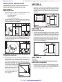
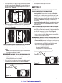
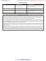
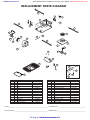
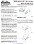
:: bathroomsource.com
Call 1-800-667-8721 anywhere in the US and Canada - www.bathroomsource.com
IMPORTANT INSTRUCTIONS OPERATING MANUAL
Models:
AK55L, AKF55
Exhaust Fan
READ AND SAVE THESE INSTRUCTIONS
READ CAREFULLY BEFORE ATTEMPTING TO ASSEMBLE, INSTALL, OPERATE OR MAINTAIN THE PRODUCT DESCRIBED. PROTECT
YOURSELF AND OTHERS BY OBSERVING ALL SAFETY INFORMATION. FAILURE TO COMPLY WITH
INSTRUCTIONS COULD RESULT IN PERSONAL INJURY AND/OR PROPERTY DAMAGE!
RETAIN INSTRUCTIONS FOR FUTURE REFERENCE.
GENERAL SAFETY INFORMATION
When using electrical appliances, basic precautions
should always be followed to reduce the risk of fire,
electric shock and injury to person, including the following:
1. Read all instructions before installing or using exhaust fan.
2. Use this unit only in the manner intended by the manufacturer.
If you have questions, contact the manufacturer.
3. Before servicing or cleaning the unit, switch power off at
service panel and lock the service disconnecting means to
prevent power from being switched on accidentally. When
the service disconnecting means cannot be locked, securely
fasten a prominent warning device, such as a tag, to the
service panel.
4. Installation work and electrical wiring must be done by
qualified person(s) in accordance with all applicable codes
and standards, including fire-related construction.
5. Sufficient air is needed for proper combustion and exhausting
of gases through the flue (chimney) of fuel burning equipment
to prevent back drafting. Follow the heating equipment
manufacturer’s guideline and safety standards such as those
published by the National Fire Protection Association (NFPA)
and the American Society for Heating, Refrigeration, and Air
Conditioning Engineers (ASHRAE), and the local code authorities.
CAUTION: FOR GENERAL VENTILATING USE ONLY. DO
NOT USE TO EXHAUST HAZARDOUS OR EXPLOSIVE MATERIALS
AND VAPORS.
6. When cutting or drilling into wall or ceiling, do not damage
electrical wiring and other hidden utilities.
7. Ducted fans must always be vented to the outdoors.
8. This unit must be grounded.
9. To avoid motor bearing damage and noisy and/or unbalanced
impellers, keep drywall spray, construction dust, etc. off
power unit.
WARNING: TO REDUCE THE RISK OF FIRE, ELECTRIC SHOCK,
DO NOT USE THIS FAN WITH ANY SOLID-STATE SPEED CONTROL
DEVICE.
WARNING: DO NOT INSTALL OVER A TUB OR MOUNT IN
A SHOWER STALL ENCLOSURE.
10. Do not install into a ceiling thermally insulated to a value
greater than R-40.
11. NEVER place a switch where it can be reached from a tub or
shower.
WARNING: DO NOT USE IN KITCHENS.
WARNING: THIS UNIT IS DESIGNED AND TESTED TO BE
A SUPPLEMENTAL HEATER FOR USE WITH A TIMER OR A
SWITCH. IT IS NOT INTENDED TO BE USED AS THE PRIMARY
SOURCE OF HEAT AND CONTROLLED BY A THERMOSTAT.
SAVE THESE INSTRUCTIONS
1
Air King at ::bathroomsource.com
powered by ::kitchensource.com
:: bathroomsource.com
Call 1-800-667-8721 anywhere in the US and Canada - www.bathroomsource.com
INSTALLATION INSTRUCTIONS
SECTION 2
CAUTION: MAKE SURE POWER IS SWITCHED OFF AT
New Construction
SERVICE PANEL BEFORE STARTING INSTALLATION.
1. Install the rails on the housing and position the housing next
to the joist. Line up housing so it will be flush with the finished
ceiling. Secure the ends of the rails with screws or nails (not
included) to the joists and slide housing into final position
(Figure 4).
SECTION 1
Preparing the Unit
1. Unpack fan from the carton and confirm that all pieces are
present. In addition to the unit you should have:
1 - Grill with Light Lens
4 - Mounting Rails
1 - Instruction/Safety Sheet
2. Remove the two hex nuts holding the light reflector in place.
Keep the reflector and nuts in the carton until needed so they
do not get damaged or lost. (Figure 1).
Housing
Joist
Figure 4
Mounting Rails
SECTION 3
Nuts
Existing Construction
Figure 1
3. Remove the fan’s venturi assembly, which is secured in place
with one screw through the venturi (Figure 2). Keep the venturi
assembly and the grill in the carton until needed so they do
not get damaged or lost.
1. Set housing in position between the joist and trace an outline
onto the ceiling material (Figure 5). Set housing aside and
cut opening, being careful not to cut or damage any electrical
or other hidden utilities. Install the rails on the housing and
position the housing in the previously cut hole so that it is
flush with the finished ceiling. Secure the ends of the rails
to the joists with screws or nails (not provided) to ensure
proper installation (Figure 4).
Screw
Figure 2
WARNING: DO NOT INSTALL OVER A TUB OR MOUNT IN
Figure 5
A SHOWER STALL ENCLOSURE.
4. Choose the location for your unit. To ensure the best air and
sound performance, it is recommended that the length of
ducting and the number of elbows be kept to a minimum, and
that insulated hard ducting be used. Larger duct sizes will
reduce noise and airflow restrictions. This fan will require at
least 7" of clearance in the ceiling,
and will mount through drywall
up to 3/4" thick. The fan mounts
between 16" on center joists using
the 4 provided mounting rails.
SECTION 4
Ducting
CAUTION: ALL DUCTING MUST COMPLY WITH LOCAL
AND NATIONAL BUILDING CODES.
1. Remove any tape that might be holding the damper in place.
Connect the ducting to the fan’s duct collar (Figure 6) and
secure in place using tape or screw clamp. Always duct the
fan to the outside through a wall or roof cap.
5. Remove the electrical knockouts
using a straight-blade screw
driver (Figure 3).
Figure 3
2
Air King at ::bathroomsource.com
powered by ::kitchensource.com
:: bathroomsource.com
Call 1-800-667-8721 anywhere in the US and Canada - www.bathroomsource.com
SECTION 6
Completing the Installation
1. Reinstall the fan’s venturi by holding it at approximately a 45
degree angle, hook the two tabs on the venturi into the slots
on the housing and secure in place by tightening the venturi
screw. Rotate the blower wheel by hand to ensure it spins
freely (Figure 8).
Figure 6
SECTION 5
Wiring
CAUTION: MAKE SURE POWER IS SWITCHED OFF AT
SERVICE PANEL BEFORE STARTING INSTALLATION.
WARNING: THIS UNIT MUST BE WIRED ON A SEPARATE
15 AMP CIRCUIT.
WARNING: USE APPROPRIATELY SIZED COPPER
CONDUCTORS ONLY RATED FOR AT LEAST 75°C.
CAUTION: ALL ELECTRICAL CONNECTIONS MUST BE
MADE IN ACCORDANCE WITH LOCAL CODES, ORDINANCES,
OR NATIONAL ELECTRICAL CODE. IF YOU ARE UNFAMILIAR
WITH METHODS OF INSTALLING ELECTRICAL WIRING, SECURE
THE SERVICES OF A QUALIFIED ELECTRICIAN.
Figure 8
2. Insert the plug from the heating unit into the receptacle marked
“HEAT”, and the plug from the fan into the receptacle marked
“VENT”(Figure 9).
1. Run wiring from wall switches carrying the appropriate rating.
One neutral (white), one ground (green or bare copper), and
three hot (red, blue, and yellow leads connected to the switch,
one for each function). Secure the electrical wires to the
housing with an approved electrical connector. Make sure
you leave enough wiring in the box to make the connection
to the fan’s receptacles.
Supply from house
2. Connect the White wire from the house to the three White
wires from the fan. Connect one Hot (Blue) wire from the
wall switch to the Blue wire from the fan (this is the fan
control). Connect second Hot (Red) wire from the wall switch
to the Red wire from the fan (this is the heat control). Connect
the third Hot (Yellow) wire from the wall switch to the Yellow
wire from the fan (this is the light control). Connect the ground
wire from the house to the Green wire from the fan (Figure
7). Use approved methods for all connections.
Ground
Heater
Vent
Figure 9
3. Remove grill from carton and open light lens area by pushing
in on the two tabs of the light lens and pulling outward from
lens. The lens will swing open on the connector bars. DO NOT
remove the lens from the grill (Figure 10).
Hot (Blue)
Hot (Yellow)
Connector Bar
Hot (Red)
Tabs
Neutral (White)
Figure 10
Figure 7
3
Air King at ::bathroomsource.com
powered by ::kitchensource.com
:: bathroomsource.com
Call 1-800-667-8721 anywhere in the US and Canada - www.bathroomsource.com
4. Install light reflector into grill by lining up the posts on grill with
the holes in light reflector (Figure 11). Raise light reflector and
grill up to housing and insert plug from light into receptacle
marked “LIGHT” (Figure 9).
8. Restore power and test your installation.
SECTION 7
Use and Care
CAUTION: MAKE SURE POWER IS SWITCHED OFF AT
SERVICE PANEL BEFORE SERVICING THE UNIT.
Post
Hole
Post
Figure 11
5. Attach light reflector in place with the two nuts removed during
Step 2 in SECTION 1 Preparing the Unit so grill fits snuggly
against ceiling (Figure 12).
Nuts
1. Cleaning the Grill: Reverse the instructions in Section 6
Completing the Installation to remove grill. Use a mild
detergent, such as dishwashing liquid, and dry with a soft
cloth. NEVER USE ANY ABRASIVE PADS OR SCOURING
POWDERS. Completely dry grill before reinstalling. Refer to
instructions in Section 6 Completing the Installation, to
reinstall grill.
2. Cleaning the Fan Assembly: Wipe all parts with a dry cloth
or gently vacuum the fan. NEVER IMMERSE ELECTRICAL
PARTS IN WATER.
CAUTION: ALLOW BULB TO COOL BEFORE REPLACING.
3. Changing the Light Bulb: Disconnect power to the unit. Open
light lens by pushing in on the two tabs of light lens and pulling
outward from lens. The lens will swing open on the connector
bars. DO NOT remove the lens from the grill (Figure 14).
Incandescent Bulb (AK55L): Unscrew bulb from lamp
holder and replace with a 100 watt maximum, type A19
medium base incandescent bulb.
WARNING: TO REDUCE THE RISK OF FIRE, USE ONLY TYPE
PL OR CF, 4-PIN CFM26W/GX24Q LAMP, 26 WATT MAXIMUM.
Figure 12
CAUTION: FAILURE TO SECURE THE REFLECTOR SCREWS
MAY RESULT IN A RATTLING OR HUMMING NOISE.
6. Install the appropriate bulb (not included) specific to your
model:
AK55L: Install a 100 watt maximum, type A19 medium base
incandescent bulb (not included).
WARNING: TO REDUCE THE RISK OF FIRE, USE ONLY TYPE
PL OR CF, 4-PIN CFQ26W/GX24Q LAMP, 26 WATT MAXIMUM.
Fluorescent Bulb: Remove lamp by gently rocking lamp
back and forth while applying outward pressure to release
the lamp from the base. Replace with Air King model
26WFL or a compatible CFM26W/GX24Q lamp.
Sylvania model: CF26DD/E/835
GE model: F26DBXT4SPX35/4P
Phillips model: PL-C 26W/835/4P/ALTO
Connector Bar
AKF55: Install an Air King model 26WFL or a compatible
CFM26W/GX24Q lamp. (not included).
Tabs
7. Close the light lens and secure in place by swinging back
into position and snapping the tabs in place (Figure 13).
Figure 14
Connector Bar
Tabs
Figure 13
4
Air King at ::bathroomsource.com
powered by ::kitchensource.com
:: bathroomsource.com
Call 1-800-667-8721 anywhere in the US and Canada - www.bathroomsource.com
Troubleshooting Guide
Trouble
1. Fan does not operate when the switch is on.
Probable Cause
Suggested Remedy
1c. Wiring is not connected properly.
1d. Motor has stopped operating.
1a. Replace fuse or reset circuit breaker.
1b. Turn off power to unit. Remove Grill and plug motor into receptacle
in housing. Restore power to unit.
1c. Turn off power to unit. Check that all wires are connected.
1d. Replace motor.
2. Fan is operating, but air moves slower than normal.
2.
2.
3. Fan is operating louder than normal.
3a. Motor is loose.
4. Heater stopped operating.
1a. A fuse may be blown or a circuit tripped.
1b. Connector plug from motor is not plugged in.
Obstruction in the exhaust ducting.
Check for any obstructions in the ducting. The most common are bird nests
in the roof cap or wall cap where the fan exhausts to the outside.
3b. Fan blade is hitting housing of unit.
3a. Turn off power to unit. Remove grill and check that all screws are fully
tightened. Restore power to unit.
3b. Call your dealer for service.
4.
4.
Thermal Cut Out switch has tripped.
Turning heater off and allowing to cool will reset the heater unit.
LIMITED WARRANTY
All products manufactured by Air King Limited are warranted for one year from the date of purchase against defects in workmanship
and/or material. In addition, all ventilating/exhaust fans, heaters, combination fan lights and/or heaters, and range hoods are
guaranteed for five years from the date of purchase against defects in workmanship and/or material.
This warranty does not cover any labor or shipping costs or the cost of replacement components as part of routine maintenance
such as: range hood grease filters, charcoal filters or combination charcoal/grease filters; replacement light bulbs in range hoods
or bathroom fan/light/bulb heater combinations. As well, any damage or failure caused by abuse, misuse, abnormal usage, faulty
installation, or improper maintenance will not be covered by this warranty.
In order to make a claim on this warranty, you must be the original consumer of the product. You will be required to present to Air
King the original bill of sale showing: date of purchase, place of purchase and model purchased. Failure to meet these requirements
will void your warranty.
Air King will not be held responsible for any bodily injury or damages to personal property or real estate whether caused directly or
indirectly by the product. Some states and provinces do not allow the exclusion or limitation of incidental or consequential damages
and some states do not allow limitations on how long an implied warranty lasts, so these exclusions or limitations may not apply to
you. This warranty gives you specific legal rights and you may have other rights which vary from state to state and province to province.
5
Air King at ::bathroomsource.com
powered by ::kitchensource.com
:: bathroomsource.com
Call 1-800-667-8721 anywhere in the US and Canada - www.bathroomsource.com
REPLACEMENT PARTS DIAGRAM
3
5
6
1
4
3
2
3
22
7
23
24
19
18
20
3
21
8
9
11
9
17
10
13
15
25
12
28
14
26
16
20
27
#
1
2
3
4
5
6
7
8
9
10
11
12
13
14
Qty.
1
3
4
2
1
1
1
1
1
1
2
1
1
2
Description
Fan Housing
Receptacle
Mounting Rails
Collar Screw
Collar
Damper
Impeller - Vent
Motor Plate
#8 Screw
Motor
Hex Nut
Lamp Holder
Reflector
Reflector Hex Nuts
Replacement Part #
5S3402073
5S3402053
5S1299002
5S3402040
5S3402041
5S3402042
5S3402074
5S3402075
5S1999004
5S2201003
5S1999006
5S3402054
5S3402055
5S1999019
#
15
16
17
18
19
20
21
22
23
24
25
26
27
28
Qty.
1
1
2
1
1
4
2
1
1
1
1
2
2
1
Description
Grill
Glass Lens
8-32 x 2-1/2" Mounting Posts
Heater Blower Housing
Heater Blower Wheel
Lock Washer
Motor Hex Nut
Heater Motor
#10 Ground Screw
14 ga Ground Wire
Lens Frame
Lockwasher - AKF55
Ballast Screws - AKF55
Ballast - AKF55
Replacement Part #
5S3402056
5S3402058
5S3402098
5S3402076
5S3402077
5S3402049
5S3402050
5S3402060
5S1999002
5S1999003
5S3402057
5S3202991
5S3202992
5S3202993
Installer: _________________________________________________________ Installation Date:_________________________________________
Place of Purchase: _________________________________________________ Model Number: __________________________________________
6
Air King at ::bathroomsource.com
powered by ::kitchensource.com