1
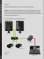
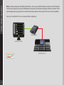
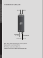
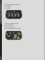
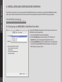
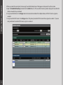
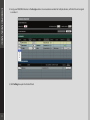
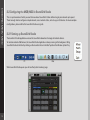
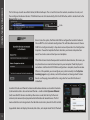
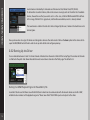
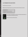
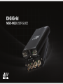
DIGIGRID MGB/MGO
1 1
DIGIGRID MGB/MGO
Table of Contents
Introduction3
About SoundGrid and the DiGiGrid MGB and MGO Audio Interfaces 3
Using DiGiGrid MGB/MGO with a Console
6
1. Hardware and Connectors
7
2. Installation and Configuration Overview
9
2.1 Configuring the MGB/MGO in MultiRack SoundGrid
9
2.2 Configuring the MGB/MGO in SoundGrid Studio
12
2.2.1 Setting up SoundGrid Studio
12
2.2.2 Setting Up the Driver
14
2.2.3 Firmware Status and Updates
15
3. MGB/MGO Control Panel
16
3.1 Clock Page
16
3.2 MADI Options Page
18
3.3 About Page 18
3.4 System Info Page
19
3.5 Saving, Loading and Identifying
19
DIGIGRID MGB/MGO
INTRODUCTION
Thank you for choosing a DiGiGrid MGB or MGO audio interface for SoundGrid systems. In order to get the most out of your DiGiGrid
product, please take some time to read this user guide. We also suggest that you become familiar with the Waves support site (www.
wavesupport.net), where you will find an extensive answer base, the latest tech specs, detailed installation guides, software updates,
and current information about licensing and registration.
About SoundGrid and DiGiGrid MGB/MGO
SoundGrid is a scalable infrastructure that provides a variety of cost-effective, high-quality solutionsfor recording studios and live
sound consoles. It can be configured in many ways and with many hardware possibilities to provide a very flexible work environment. This framework is managed by the SoundGrid Studio Application or MultiRack SoundGrid, which configures the network,
assigns and manages I/Os, controllers and servers, and patches audio throughout the system. Any user, anywhere on the SoundGrid
network, has access to any of the network’s I/O devices. Adding a SoundGrid DSP server enables recording and monitoring with very
low latency and moves processing away from the host computer to the server.
A single Ethernet cable connects all devices in the SoundGrid network.
The DiGiGrid MGB and MGO MADI-to-SoundGrid interfaces are used for connecting MADI-enabled devices to a Waves SoundGrid
network for plugin processing and/or DAW playback and recording. The MGB unit is equipped with MADI BNC connections; MGO is
equipped with MADI optical connections.
■
■
■
■
■
■
■
3
S upported sample rates: 44.1, 48, 88.2 and 96 kHz
1
12/128-channel I/O @ 48 kHz
5
6/64-channel I/O @ 96 kHz
S upports 56- and 64-channel modes
Supports double wire (48k frame) and single wire (96k frame) signals @ 96 kHz
Clock synchronization via word clock input, MADI (Port 1 or Port 2), SoundGrid (Sync over Ethernet), Internal
1 SoundGrid port (RJ45)
DIGIGRID MGB/MGO
Typical Uses
DiGiGrid MGO and MGB interfaces may be used in both SoundGrid and Native configurations, as follows:
SoundGrid: In a SoundGrid configuration, the MGB or MGO interface is used to connect a MADI-enabled console to a SoundGrid
network, for plugin processing and simultaneous DAW playback and recording. The SoundGrid configuration uses a dedicated
SoundGrid DSP server to power the plugin processing, enabling super-low latency, high plugin counts, and networking capabilities,
with the option of an additional backup DSP server.
Please note: A SoundGrid DSP server is required for SoundGrid configurations.
DAW / SG Studio
MultiRack SG
Network
Switch
Server
DiGiGrid MGB/MGO
Optional Backup Server
Ethernet
MADI
MADI Enabled Console
4
DIGIGRID MGB/MGO
Native: In a Native configuration, the MGB or MGO interface is used to connect a MADI-enabled console to the SoundGrid ASIO/Core
Audio driver, for plugin processing and/or DAW playback and recording. Since the Native configuration utilizes the computer’s CPU to
power the plugin processing, plugin count and overall system latency depend on the computer’s CPU and sound driver capabilities.
Please note: A SoundGrid DSP server is not required for Native configurations.
DiGiGrid MGB/MGO
MultiRack Native or DAW
Ethernet
MADI
5
MADI Enabled Console
DIGIGRID MGB/MGO
Using DiGiGrid MGB/MGO with a Console
■ Connect your MGB to the console using BNC MADI cables. Connect your MGO to the console using optical MADI cables.
■ Connect to the SoundGrid network using Cat 5e or Cat 6 cables. Connect the MGB/MGO interfaces to your computer’s local LAN
port, or use two cables to connect the MGB/MGO and your computer to the SoundGrid-compatible network switch.
Native/SoundGrid Comparison Table
Features
Native
SoundGrid
■
Low Latency
Processing
■
■
Recording
■
■
■
Simultaneous Recording and Processing
CPU Load
6
Your DAW computer's CPU
Dedicated SoundGrid DSP server
Backup DSP Server
■
Networking
■
I/O Interface
MGB/MGO
MGB/MGO
Plugin Host Software
MultiRack Native
MultiRack SoundGrid
Plugin Licenses
Native
SoundGrid
DIGIGRID MGB/MGO
1. HARDWARE AND CONNECTORS
MADI 1 I/O
Waves SoundGrid
Network Port
Word Clock Input
MADI 2 I/O
5V DC Power Input
Status LED
MADI 1 & MADI 2 – Either BNC (MGB) or optical (MGO). Connect to any MADI device.
Waves SoundGrid Port – Connect to SoundGrid Network.
Word Clock Input – Connect to external word clock source.
5V Power Input – Use only DiGiGrid-supplied or approved external power supply.
7
DIGIGRID MGB/MGO
Status LED – Colors and respective status as follows:
■ Green = MADI link
■ Off = no MADI link
■
■
■
■
8
F lashing red = network cable not connected
Blue = network connected
ALL colors sequence = IDENTIFY
Yellow = while updating or when card is stuck in boot
DIGIGRID MGB/MGO
9
2. INSTALLATION AND CONFIGURATION OVERVIEW
The ASIO/Core Audio drivers and control panel for the MGB/MGO interfaces are installed using the DiGiGrid MGB/MGO installer,
which also installs the SoundGrid driver and the SoundGrid Studio Application required for DAW recording and playback.
DiGiGrid MGB/MGO downloads page:
www.waves.com/downloads/DiGiGrid-mgb-mgo
2.1 Configuring the MGB/MGO in MultiRack SoundGrid
Access the MGB/MGO control panel via the Inventory window in the
MultiRack SoundGrid application.
1. Launch the MultiRack SoundGrid Application.
2. E nter the Preferences window by typing Ctrl+P (Windows) or
Cmd+P (Mac), or from the appropriate application menus.
3. Under Local LAN Port, choose the adapter that is connected to the
SoundGrid network/MGB/MGO. Network adapters are displayed as
MAC addresses and port names.
DIGIGRID MGB/MGO
10
4. When you select the correct port, the message “SoundGrid Network Found” will appear on the panel. Close this window.
5. O
pen the SoundGrid Inventory window from the Audio Menu (F2). The SoundGrid Inventory window displays all SoundGrid I/O
devices connected to your network.
6. A
ssign SoundGrid drivers in the Assign column. Use consecutive numbers for multiple devices, with the first unit assigned as
number 1.
7. A
ssign SoundGrid DSP servers in the Assign column. The primary SoundGrid DSP server will be assigned as number 1. If you are
using a redundant SoundGrid DSP server, assign it as number 2.
DIGIGRID MGB/MGO
8. Assign your MGB/MGO devices in the Assign column. Use consecutive numbers for multiple devices, with the first unit assigned
as number 1.
9. Click Settings to open the Control Panel.
11
DIGIGRID MGB/MGO
2.2 Configuring the MGB/MGO in SoundGrid Studio
This is a quick overview of what you need to know about SoundGrid Studio software to get your network up to speed.
There’s enough here to configure a simple network, assess network status, and set up your I/O devices. For more complex
configurations, please refer to the SoundGrid Studio user guide.
2.2.1 Setting up SoundGrid Studio
The SoundGrid Studio Application oversees the SoundGrid network and manages all network devices.
To maintain network effectiveness, the SoundGrid Studio Application is always running in the background. Bring
SoundGrid Studio to the front by clicking on the SoundGrid icon in the Mac Top Bar or the Windows System Tray.
PC
When SoundGrid Studio opens you will see the System Inventory page.
12
Mac
DIGIGRID MGB/MGO
The first time you launch SoundGrid Studio, the Wizard will open. This is a tool that scans the network, inventories its assets, and
then configures the relevant devices. If the Wizard does not start automatically, click the SCAN button, which is located next to the
Network Port window.
Scan
Once it scans the system, the Wizard will offer to configure the SoundGrid network.
Choose NEXT to start automatic configuration. This will take a few moments. Choose
CANCEL to configure manually. A drop-down menu will provide a list of configuration
templates. Choose the template that best describes your devices and production
needs. You can also save and load your own templates.
If the Wizard cannot locate the requested SoundGrid network devices, this means you
may have chosen an incorrect network port on your computer. Check the physical
connections and then click SCAN. When configuration is complete, close the window.
If there is still a problem, you can configure your system manually. Use the System
Inventory page to assign devices, control the network, and manage clock. To learn
how to use this page, please refer to the user guides for SoundGrid Studio and
StudioRack.
SoundGrid Studio uses Ethernet to stream audio between devices on a SoundGrid network.
Synchronization clock is also carried over Ethernet—a method called Sync over Ethernet
(SoE). SoundGrid I/O devices can clock by other means as well, but SoE is by far the most
common (and convenient) way to provide clock information to network devices. The first
device added to a rack is designated as the SoE clock master and is placed in the first rack slot.
A populated device slot displays the mode, clock status, and sample rate of the I/O. The clock
13
DIGIGRID MGB/MGO
master device is indicated by its blue color and the icon text: On, Master Clock, INT (48 kHz).
To add another SoundGrid device, click on the arrow in an empty rack slot. From the list of available
devices, choose the one that you want to add—in this case, a DiGiGrid MGB coaxial MADI interface.
In this image, DiGiGrid DLS is grayed out, and therefore unavailable, since it is already claimed.
The new device is visible in the rack slot. Unless changed by the user, it remains the clock slave and is
colored green.
Now you know how to assign I/O devices and designate a device as the clock master. Click on the Gear symbol in the device slot to
open the MGB/MGO Control Panel in order to set up clock details and configure preamps.
2.2.2 Setting Up the Driver
You can allocate between 32 and 128 driver channels. Allocate driver channels in Rack B of the Setup Page. The number of channels
is reflected in the patch tabs: fewer allocated channels means fewer channels in the Patch page. The default is 32.
Setting the DAW Playback Engine for SoundGrid I/Os
SoundGrid Studio uses the Waves SoundGrid ASIO/Core Audio driver to communicate with all network devices and with a DAW,
whether local or remote. Set the playback engine to “Waves SoundGrid.” Patch DAW inputs and outputs to the driver.
14
DIGIGRID MGB/MGO
2.2.3 FIRMWARE STATUS AND UPDATES
On the left of the device icon are two buttons:
FW indicates the status of the device’s firmware. The user is given the choice to update it. Status indications are color-coded:
Grey
Compatible firmware
Blue
Compatible firmware, but a newer version exists
Red
Firmware not compatible and must be updated in order to use
Click on the FW button to launch the Reflasher. This will initiate a scan of the hardware and then offer options. Do
not disconnect device or turn off computer until you see “Done.”
ID activates LEDs on the front panel of the hardware device.
15
DIGIGRID MGB/MGO
16
3. MGB/MGO CONTROL PANEL
If you are working with MultiRack SoundGrid, access the MGB/MGO Control Panel via the Inventory window.
If you are using SoundGrid Studio, click on the Gear symbol in the device slot to open the MGB/MGO Control Panel.
3.1 Clock Page
When you launch the DiGiGrid MGB/MGO driver Control Panel, it will load the Clock page. The following settings are available in the
Clock Settings window:
■ SOURCE sets the clock source.
- Internal – The interface itself provides the clock.
- External WC – The interface has a Word Clock Input connector to connect an external clocking source in order to sync all devices
in your network to the external clock.
- Sync over Ethernet – Send or receive word clock/sample rate over an Ethernet cable between DiGiGrid network devices.
- Digital – Syncs via the BNC or optical MADI connection on MADI Port 1 or Port 2 (selectable). The MGB/MGO interfaces sync to the incoming MADI from the console.
DIGIGRID MGB/MGO
■ SAMPLE RATE sets the sample rate when Clock Source is set to Internal. Range: 44.1 / 48 / 88.2 / 96 kHz.
■ S
AMPLE RATE MODE sets the MADI mode for 88.2 / 96 kHz operation; check your console manual for the proper selection.
Range: High Speed, SMUX.
■
■
■
■
17
STATUS displays synchronization status (Sync or No Sync).
C
URRENT CLOCK SOURCE IS displays the current sync method.
S
oE displays Sync over Ethernet status (On or Off ).
CLOCK SOURCE AUTO-SWITCHING allows the MGB/MGO driver to switch between clock sources if it finds a higher priority
source than the currently selected source. Sync priority order is: SoE, WC, Digital 1, Digital 2, and Internal.
DIGIGRID MGB/MGO
3.2 MADI Options Page
One MADI connection supports 56 or 64 in/out channels at 44.1/48 kHz, and 28 or 32
in/out channels at 88.2/96 kHz.
In MADI Port Settings, set the number of available channels according to your
console settings.
3.3 About Page
The About page displays an overview of the device’s specifications.
18
DIGIGRID MGB/MGO
3.4 System Info Page
The System Info page displays the device’s connection status, manufacturer, model,
MAC and SoE Master MAC addresses, and firmware version.
3.5 Saving, Loading and Identifying
LOAD and SAVE (at the top left corner of the Control Panel window) allow you to save and load your MGB/MGO settings.
IDENTIFY (at the top right corner of the Control Panel window) allows you to identify connected devices if multiple MGB/MGO
interfaces are being used. The Status LED will cycle through colors instead of displaying a single status color.
19