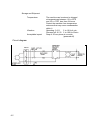
1
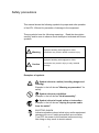
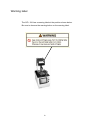
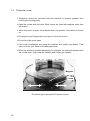
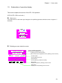
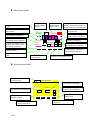
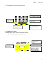
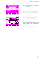
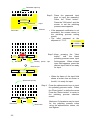
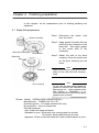
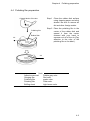
DOCUMENT NUMBER OFL-15 SERIES OFL-15A OFL-15 5002 FIBER POLISHER ( UNIVERSAL TYPE PROGRAMMABLE ) INSTRUCTION MANUAL API-54E1-02 OFL-15A SERIES OFL-15 5002 FIBER POLISHER ( UNIVERSAL TYPE PROGRAMMABLE ) INSTRUCTION MANUAL Document Number API-54E1-02 First Edition April 2005 Second Edition June 2005 Copyright 2005 by SEIKOH GIKEN Co., Ltd. All rights reserved. SEIKOH GIKEN Co., Ltd. (SG) has prepared this manual for use by SG personnel, licensees, and customers. The information contained herein is the property of SG and shall not be reproduced in whole or in part without the prior written approval of SG. SG reserves the right to make changes without notice to the specifications and materials contained herein and shall not be responsible for any damages (including consequential) caused by reliance on the materials presented, including but not limited to typographical, arithmetic, or listing errors. is a trademark of SEIKOH GIKEN Co., Ltd. Please address any questions, comments, and suggestions to: SEIKOH GIKEN Co., Ltd. Optical Communications Group 296-1, Matsuhidai, Matsudo-shi, Chiba 270-2214 Japan TEL: +81-47-388-6111, FAX: +81-47-388-4477 http://www.seikoh-giken.co.jp E-mail: [email protected] ii Table of contents Preface Safety precautions Warning label Precautions for use Chapter 1 User notes 1.1 1.2 1.3 1.4 1.5 1.6 Check on delivered items Items to be prepared by user Part names Protection cover Explanation of operation display Procedure of programmed polishing Chapter 2 Installation 2.1 2.1.1 2.1.2 2.1.3 2.1.4 2.2 Installation environment Operation environment Power supply Precautions for unpacking Installation space Return of arm to home position Chapter 3 Setting polishing process 3.1 Setting new polishing process name 3.2 Setting new polishing process Chapter 4 Polishing preparation 4.1 4.2 4.3 4.4 Base disk preparation Polishing disk preparation Rubber disk preparation Polishing film preparation i ii iv v 1-1 1-2 1-5 1-6 1-8 1-9 1-15 2-1 2-1 2-1 2-2 2-2 2-3 2-4 3-1 3-1 3-3 4-1 4-1 4-2 4-2 4-3 Table of contents-1 Chapter 5 Polishing procedure 5.1 5.2 5.3 5.4 5.5 5.6 Mounting the ferrules Removing adhesive (for Flat ferrule polishing) Adjusting fiber holder UPC polishing condition Polishing step Polishing condition check Chapter 6 Setting manual polishing 6.1 Setting manual polishing conditions Chapter 7 Changing password 7.1 Procedure for changing password 5-1 5-1 5-5 5-6 5-7 5-8 5-12 6-1 6-1 7-1 7-1 Chapter 8 Maintenance 8-1 8.1 8.2 8-1 8-1 Cleaning after polishing Changing polishing film Chapter 9 Troubleshooting 9.1 9.2 9-1 Resetting error Other troubleshooting 9-1 9-4 Standard polishing efficiency and specifications Circuit diagram A-1 A-2 Appendix Table of contents-2 Preface This manual has been prepared to provide the information necessary to allow the user to operate the OFL-15A Universal Polisher correctly and fully utilize its functions. Before using the OFL-15A, be sure to read this instruction manual thoroughly. Keep the manual at a place for future reference. Note The ferrules that can be used on the standard polishing fixture attached to the polisher are only those meeting the following requirements: · Ferrule material Zirconia · Ferrule outer diameter f2.5mm Please contact SII for optional fixtures and consumables if you wish to polish other types of ferrules with a different outer diameter, or ferrules that require another style of polishing such as PC polishing. Note The polishing film and polishing fluid are selected especially for the processes performed on the OFL-15A. If you use any other polishing film or fluid, SII cannot guarantee that the polishing specifications will be met. Before using the OFL-15A, be sure to read "Safety precautions" and "Precautions for use" carefully for proper operation. i Safety precautions This manual shows the following symbols for proper and safe operation of the OFL-15A and for prevention of damage to the equipment. These symbols have the following meanings. Read the description carefully and be sure to observe such description indicated with these symbols. ! ! Warning Improper handling with negligence of this precaution may result in death or serious injury. Caution Improper handling with negligence of this precaution may result in injury or only material damage. Examples of symbols ! Symbol refers to caution (including danger and warning). Example in the left shows "Warning or precaution" for safety. Symbol refers to prohibition. Example in the left shows "No disassembly". Symbol refers to forced action or instruction. Example in the left shows "Unplug the power cable from the outlet". ELECTRIC SHOCK Indicates situations where lethal injury and/or equipment damage will occur if safety precautions are not taken. Turn OFF the power to the machine before servicing. Not doing so may result in electric shock. ii ! Warning Never touch or gain access to the rotating part, the arm or the fiber holder with your hand or finger during operation. Otherwise, you may be injured. Do not touch the operation panel or the switch with wet hand or do not connect/disconnect the power cable with wet hand. Otherwise, you may get electric shock. Be sure to use the specified voltage and connect the grounding terminal (Class 3 grounding or greater). Otherwise, fire, electric shock, accident or failure may occur. Turn off the power and unplug the cable from the outlet for the following cases. Otherwise, electric shock, fire or accident may occur. · · · When the polishing disk is replaced. When a fuse is replaced. When abnormality of the OFL-15A such as smoke or abnormal noise is detected. ! Caution Never perform the following actions. accident or failure may occur. Otherwise, fire, electric shock, Do not place an object on the OFL-15A. Do not leave the OFL-15A outdoors or at the place where it is exposed to water. · Do not give impact to the OFL-15A or drop the OFL-15A. · The OFL-15A is heavy. Make sure to use it on a rigid table. · Do not place an object on the power cable. Do not twist or pull the cable strongly. · · iii Warning label The OFL-15A has a warning label at the position shown below. Be sure to observe the warning/notice on the warning label. iv Precautions for use Pay attention to the following points for operation of the OFL-15A. · Do not use the OFL-15A to polish items other than ferrules and optical connector plugs provided by SG. · Do not disassemble or modify the OFL-15A with the way not specified in this manual. Otherwise, accident or failure may occur. · If you get the polishing fluid on your skin or in your eyes, rinse thoroughly with water as quickly as possible. · Make sure the area where the polishing fluid is being used is well ventilated. · If the polishing fluid gets on your clothes, they should be washed thoroughly. · After using the polishing fluid, seal the container and store it in a place that is between 0 °C and 50 °C (between 32 °F and 122 °F). · SG does not assume any responsibility for products manufactured with the OFL-15A. v Chapter 1 User notes This chapter describes the delivered parts, part details and operation procedure. Section 1.1 describes check on the delivered parts. Section 1.2 describes the items to prepared other than the OFL-15A and its accessory parts. Section 1.3 describes part names of the OFL-15A and their functions. Section 1.4 describes the protection cover. Section 1.5 describes the operation display. Section 1.6 describes the standard operation procedure to polish the ferrules with a program on the OFL-15A. 1-1 1.1 Check on delivered items Make sure that all accessory parts are present before using the OFL-15A. No . Part Part code Qty Remarks 1 Machine OFL-15 5002 1 ---------- 2 Base disk KMD100110 1 ---------- 3 Power cord KKo100420 4 Fuse KMo100310 1 1 5 Instruction manual API-54E1-01 1 ---------- 6 Holding jig rest Kjo100600 1 ---------- 7 Grease Kjo101200 1 ---------- 8 Maintenance manual APM-39E-02 1 (There is no picture showing.) 250V,2.5A *The listed quantity is the quantity included in the OFL-15A package. See Standard Consumable Parts and standard polishing jig and disk on pages 1-4 for the quantities included in an additional order set. 1-2 Chaptar 1 User notes #1 Machine Base disk is mounted on the polisher body Accessories of polisher and some of custom made parts 1-3 (Standard consumables) The following products are available as standard consumables. Part Part code Polishing film (adhesive removal) Polishing film (grinding) Polishing film (polishing) Polishing film (finishing) Cleaning sheet KJWZM00A01 Rubber Pad (adhesive removal) (finishing) Rubber Pad (grinding, polishing) Rubber Pad (cleaning) Qty. Remarks (Count and quantity are only guideline.) 100 sheets Change after every 2 uses KJW100230 10 sheets Change after every 18 uses KJW100440 10 sheets Change after every 10 uses KJW101500 100 sheets Change after every 2 uses KJW101601 10 sheets KLP101540 1 piece Change after 1 year KLP101510 1 piece Change after 1 year KLP101520 1 piece Change after 1 year Change after every 50 uses (Standard polishing jig and disk) Part Holding jig (V-groove type) Holding jig (Hole type) Polishing disk 1-4 Remarks Part code Qty. KKJ101101 1 piece For 12 pieces KKJ101701 1 piece For 24 pieces KMD100100 1 piece For UPC,Adpc,SPC,PC polishing Chapter 1 1.2 User notes Items to be prepared by user In addition to the main polisher and its accessories, please prepare the following items: ① Cleaning paper (Recommended paper: Dusper, Ozu Corporation) ② Ethyl alcohol ③ Distiled Water ④ ⑤ ⑥ ⑦ Container for cleaning Holding jig and tool Polishing disk Consumable Three 3 liter containers for cleaning process Rubber Pad Polishing film ect. 1-5 1.3 Part names This section explains the part names of the OFL-15A and their functions. ⑫ OFL-15A does not have this cover #7 Fiber holder #5 Arm (#10 Position for the arm fixing block when it is used) #11 Protection cover #6 Base disk (This figure does not show the base disk). #2 Operation display #4 Power lamp #3 Stop switch #8 Fuse holder #1 Power switch #9 AC inlet Front view Back view #10 is only used OFL-15A . The above figure shows the condition before setting the base disk and polishing disk. 1-6 Chapter 1 User notes #1 Power switch Switches the power ON/OFF. #2 Operation display The polishing process and the conditions are set on this display. Manual operation such as start/stop of grinding, rotation of the polishing disk, upward/downward movement of the arm, etc. is also enabled on this display. #3 Stop switch Press this switch to stop the polishing operation immediately. #4 Power lamp Lights when the power is supplied. #5 Arm The polishing jig is mounted. #6 Base disk The polishing disk, the rubber disk and various polishing films are set on this disk. Using the amount of the rubber disk set, convex spherical polishing is performed. #7 Fiber holder The fiber cable is placed. #8 Fuse holder Holds a 2.5 A fuse. #9 AC inlet AC inlet for connection to the power cable. #10 Position for the arm fixing block when it is used. #11 Protection cover When the cover is open, the polishing machine dose not work if the switch is turned on. 1-7 1.4 Protection cover · Protection covers are provided with this machine to prevent operator from touching the moving parts. · Open the covers with the knob. Each covers are fixed with magnets when they are closed. · When the cover is open, the machine does not operate if the switch is turned on. · Do not pinch your fingers when you open or close the covers. · Do not force the cover open. · if the cover is damaged, stop using the machine and contact your dealer. Take care not to cut your hand on the damaged cover. · When the machine operates abnomally, for example, the machine operates with the covers open, stop using the machine and contact your dealer. Magnets Knob The above figure shows the Protection covers. 1-8 Chapter 1 1.5 User notes Explanation of operation display This section explains the screen of the OFL-15A operation. (LCD of OFL-15A is not color.) Start screen (The start screen in the lower right changes to the polishing process selection screen in approx. 3 seconds.) SII Seiko Instruments Inc. OFL-15 OPTICAL FIBER SOFTWARE Revision : 0.00 Date : 08/20/1999 Polishing process selection screen POLISHING PROCESSES SELECT PROCESS-1 UPC Screen of polishing processes (Processes are available from 1 to 5.) Polishing process selection button: (Max. 3 items can be registered in each polishing process screen.) Process button: Set the polishing process. Manual button: Set the polishing conditions manually. PROCESS MANUAL NEXT BACK Back button: Displays the previous polishing process screen. Next button: Displays the next polishing process screen. 1-9 Main menu screen Displays the selected polishing process. Cursor to move the polishing step to the left. Selected polishing step. Highlighted when selected. MAIN MENU - NEW (STOP) Polishing thrust monitor: The thrust during polishing is displayed. STEP Polishing thrust set value: The set polishing thrust is displayed. Count 1000 g /Time Mon. 00 m 00 s 0001 / Time 00 m 30 s RESET SETTING ERROR MANUAL PROCESS Stop button: Stops the machine operation. Press this button twice to return the machine to the initial status. Cursor to move the polishing step to the right. Rotation speed setting value: The set rotation is displayed. 1 2 3 4 5 Press Setting button: Sets the polishing condition. STOP Press Mon. -0300 g /Table rotate 0180 rpm Counter: The polishing count is displayed. The number can be reset with the reset button. Error button: Checks the error status. Displays the current machine operation status. RUN Time monitor: Time after start of polishing is displayed. Polishing time setting value: The set polishing time is displayed. Run button: Performs the selected polishing process. The button is highlighted during operation. Process button: Returns to the polishing process selection screen. Manual button: Performs manual polishing. Setting check screen Selected polishing process and polishing step Polishing thrust set value: The set polishing thrust is displayed. Main button: Returns to the main menu screen. Back button: Moves to the previous polishing step. 1-10 UPC Pro cess No.1 Process Setting (No.1) Press 2500 MAIN g BACK Rotation speed setting value: The set rotation is displayed. Table Rotate Time 180 00 MIN 30 SEC rpm NEXT SETTING Polishing time setting value: The set polishing time is displayed. Setting key: The polishing condition is set. Next button: Moves to the next polishing step. Chapter 1 User notes Polishing process name registration screen A B C D E F G H I Alphanumeric key: Keys to input the name for each field J K L M N O P Q R S T Next button: Moves to the next polishing process. U V W X Y Z . - CLR 1 2 3 8 9 4 6 5 7 0 Field to input the polishing process name UPC NEXT ENT RETURN Return button: Ends the polishing process name registration and returns to the polishing process selection screen. Enter button: Button to define the input name for each polishing process Password input screen Password must be input to register or change the conditions. (The initial password at the shipment is "1111".) 1 2 3 CLR Enter button: Button for certification of the input password. 4 BS 5 6 ESC 7 8 9 0 Password input key: Keys to input the password (4 digits) Field to input the password PASSWORD ENT OK OK button: When the input password is certified, the setting screen appears. When not certified, the previous screen appears. 1-11 Polishing process condition setting screen Input is enabled when the parameter input field for registration/change of the condition is pressed. Polishing thrust setting value: Input the desired polishing thrust. 1 2 3 5 BS CLR Pro cess Press No.1 2500 Selected polishing step Next button: Moves to the next polishing step. 4 6 ESC 8 9 0 Time 180 00 MIN 30 SEC rpm ENT Setting condition input key: Keys to input the setting value for each field. Rotation speed setting value: Input the desired rotation. Table Rotate g NEXT 7 RETURN Polishing time setting field: Input the desired polishing time. Return button: Ends the polishing process condition setting and returns to the setting check screen. Enter button: Button to define the input setting for each parameter Manual screen Table Rotate Run button: Rotates the polishing disk at the set rotation speed. Press set button: Moves down the arm to apply thrust. MANUAL Process Press reset button: Returns the arm to the initial position. Polishing thrust field: Displays the set polishing thrust and the monitor value. Rotation field: Displays the set rotation speed of the polishing disk and the command value. Press Set Reset (Setting .Real Data) Press Table 0150 , 0000 rpm Rotate Main button: Returns to the Main Menu screen. If the arm is not at the initial position and the polishing disk is not in operation, the Main Menu screen does not appear. 1-12 2000 , 00063 g MAIN Table Rotate RUN STOP Time 00 m 20 s set Time 00 m 00 s MANUAL SETTING Table Rotate Stop button: Stops rotation of the polishing disk. Polishing time setting value: Displays the set polishing time. Time monitor: Time after start of polishing is displayed. Manual setting button: Sets polishing conditions manually. Chapter 1 User notes Manual condition check screen Rotation speed setting value: The set rotation is displayed. MANUAL Process Setting Polishing thrust setting value: The set polishing thrust is displayed. Pro cess MAN. Press 2500 Main button: Returns to the Main Menu screen. Table Rotate Time 180 00 MIN 30 SEC g rpm MAIN MANUAL SETTING Polishing time set value: The set polishing time is displayed. Setting button: The polishing condition is displayed. Manual button: Returns to the manual screen. Manual condition setting screen Press the parameter input field for registration/change of the condition to be ready for input. 1 2 3 Polishing thrust setting value: Input the desired polishing thrust. Enter button: Button to define the input setting for each parameter. CLR 4 5 BS Pro cess Press MAN. 2500 6 ESC g 7 8 9 0 Rotation speed setting value: Input the desired rotation. Table Rotate Time 180 00 MIN 30 SEC ENT rpm Setting condition input key: Keys to input the setting value for each field. RETURN Polishing time setting field: Input the desired polishing time. Return button: Manual setting registration button for each parameter. 1-13 Error screen 99/09/22 STOP Error list The error details are displayed (listed) for each error. MAIN Main button: Returns to Main Menu screen. Up/down scroll cursor: Scrolls the error list. DEL DEL button: Deletes an error message. RESET Reset button: Recovers the operation display to be ready for polishing. When this button is ON, polishing cannot be performed. Refer to Section 9.1 "Resetting error". Be sure to remove the cause of the error and press this button to reset the error status. 1-14 Chapter 1 1.6 User notes Procedure of programmed polishing This section describes the standard procedure for programmed polishing of ferrules using the OFL-15A. Refer to the description in the following pages. Refer to (1). Check the ferrule conditions. * Amount of adhesive applied to the ferrule edge Preparation Chapters 3 and 4 Setting new polishing process name Sec. 3.1 Setting new polishing process Sec. 3.2 Base disk preparation Sec. 4.1 Polishing disk preparation Sec. 4.2 Rubber disk preparation Sec. 4.3 Polishing film preparation Sec.4.4 Chapter 5 Polishing procedure Refer to (2). Mounting the ferrules Sec. 5.1 Removing adhesive (Hand Polish) for Flat ferrule polishing Sec. 5.2 Adjusting for holder Sec. 5.3 Polishing step Sec. 5.5 Polishing condition check Sec. 5.6 Refer to (3). Repolishing Failure End of polishing 1-15 (1) It is best to use only a small amount of adhesive on the tip of the ferrule. If too much is used, it may talke longer than the standard 30 seconds of manual polishing for removing the adhesive. (for Flat ferrule ) Adhesive removal step for predome ferrule use machine. (2) The polishing film, polishing fluid, and polishing conditions used in each of the polishing steps are listed below. Refer to the details for each of the polishing steps in the corresponding sections. Polishing step and Machine rotation number Polishing film and rubber pad Polishing fluid Thrust (Std.) Polishing time (Std.) Polishing film life (guideline) Adhesive removal Pebble grey color 500g Rotation number Distilled Water+ 1.0 min. (KJWZM00A01) 2 times (max. 48 ferrules) Distilled Water 4400g 0.5 min. 18 times (max. 432 ferrules) Distilled Water+ 3800g 1 min. 10 times (max. 240 ferrules) Distilled Water 3800g 2 min. 2 times (max. 48 ferrules) Distilled Water 600g 20sec 50 times (max.1200 ferrules) 220 rpm Ruber pad KLP101540 Grinding Red color Rotation number Rubber pad KLP101510 280 rpm Polishing Purple color Rotation number (KJW100440) Rubber pad KLP101510 240 rpm Finishing Rotation number 220 rpm Cleaning Rotation number 220 rpm (KJW100230) Ethyl alcohol Clear color (KJW101500) Ethyl alcohol Rubber pad KLP101540 Brown color Rubber pad KLP101520 *The polishing thrust (pressure) varies according to the number of ferrules mounted on the holding jig. Refer to Section 3.1 Setting polishing process when setting the thrust. (3) Mount the ferrules in the holding jig evenly according to the procedure. If the ferrules are mounted incorrectly, the ferrules can slip and the tips of the ferrules may not be polished throughly. When mounting less than 12 or 24 ferrules on the holding jig, make sure that they are arranged in a balanced pattern, according to the procedure. An unbalanced arrangement of ferrules on the holding jig may cause the ferrules to be polished unevenly. 1-16 Chapter 2 Installation This chapter describes the environmental conditions for installation of the OFL-15A, precautions for unpacking and return of the arm to the home position. 2.1 Installation environment The environment conditions for installation of the OFL-15A are as follows: 2.1.1 Operation environment Use the OFL-15A within the range of temperature and humidity shown below: Temperature: Relative humidity: Storage temperature: 10 - 40°C 15 - 85%RH (no condensation) 0 - 50°C Do not install the OFL-15A at the following places: · Where the machine is exposed to the direct sunlight · Where there is excessive changes in temperature · Where there is frequent mechanical vibration · Where the machine is exposed to dust · Where the area is poorly ventilated 2-1 2.1.2 Power supply The power supply conditions for the OFL-15A is as follows: Power voltage( single phase +/- 10% ) AC220-240V Power frequency 50/60 Hz +/- 5% Power consumption 80 W ! Warning Be sure to connect the grounding terminal from the power plug. Otherwise, electric shock, fire or accident may occur. 2.1.3 Precautions for unpacking When unpacking the OFL-15A, pay attention to the following points. ! Warning Do not take the OFL-15A out of the package alone. Otherwise, you may be injured. ! Caution Do not hold the arm when taking the OFL-15A out of the package. Otherwise, malfunction may occur. 2-2 Chapter 2 Installation 2.1.4 Installation space Fig. 2-1 shows the installation space for the OFL-15A. 200 or more 400 or more 250 253 Installation area 753 or more 250 or more Table 100 or more 500 or more 1218 or more or more 618 600 700 or more Fig. 2-1 Installation space 2-3 2.2 Return of arm to home position The OFL-15A has its arm position lowered when shipped from the factory. After installation of the OFL-15A, return the arm to its home position. (Spacer is not attached OFL-15A) Spacer Step 1 Remove the spacer protecting the arm of the polisher. ! Caution If you carry the OFL-15A, Insert the Spacer on the arm or fix the arm by tape. Otherwise, OFL-15A’s Load Sensor may be damaged. Step 2 Power switch POLISHING PROCESSES SELECT PROCESS-1 UPC PROCESS MANUAL 2-4 NEXT BACK Insert the power cable into the AC inlet at the back of the polisher and turn on the power switch. ! Warning Be sure to connect the grounding terminal from the power plug. Otherwise, electric shock, fire or accident may occur. Wait for the screen in the left to appear on the operation display. Chapter 2 Installation Step 3 Press the "UPC button" shown in the left. POLISHING PROCESSES SELECT PROCESS-1 UPC Press For details of the operation display, refer to Section 1.4 "Explanation of operation display" PROCESS MANUAL MAIN MENU - UPC STEP NEXT BACK (STOP) STOP Step 4 Press the "Stop button" shown in the left immediately. 1 2 3 4 5 Press Mon. 00000 g /Table rotate 0000 rpm Press Count 0000 g /Time Mon. 00 m 00 s RESET 0000 / Time 00 m 00 s SETTING ERROR MANUAL PROCESS RUN The arm automatically returns to the home position. When the arm stops, press the power switch to turn off the power. If the error message “ STOP “ appears on the error display screen, refer to Chapter 9 “ troubleshooting “ . 2-5 Chapter 3 Setting polishing process The UPC polishing process has been pre-installed on the OFL-15A polisher. In addition to the pre-installed polishing process, 14 polishing processes can be registered. To change the process or to register a new polishing process, please read this chapter. When the power is supplied, the start screen appears for 3 seconds and the polishing process selection screen then appears. POLISHING PROCESSES SELECT PROCESS-1 SII Seiko Instruments Inc. UPC OFL-15 OPTICAL FIBER SOFTWARE Revision : 0.00 Date : 08/20/1999 Start screen 3.1 PROCESS MANUAL NEXT BACK Polishing process selection screen Registration of new polishing process name The polishing process name can be registered. POLISHING PROCESSES SELECT PROCESS-1 UPC PROCESS MANUAL NEXT Step 1 Register the polishing process name. Press the "Process button" on the polishing process selection screen. BACK Process button 3-1 Password input key 1 2 3 CLR 4 5 BS 6 7 8 9 0 ESC Step 2 PASSWORD Password ENT input OK OK button Enter button A B C D E F G H I J If the password certification is not successful, the screen returns to the polishing process setting screen. · The initial password at the shipment is "1111". PASSWORD · 1111 K L M N O P Q R S T U V W X Y Z . - CLR 1 2 3 8 9 4 5 6 7 NEXT 0 Step 3 Keep pressing the "Next button" until the blank RETURN polishing process name input field appears. When a blank Polishing process input input field appears, press the desired input field to be ready Ready for input for input. Press UPC Press the password input keys to input the password. Press the "Enter button". Press the "OK button" and the screen to set the polishing process name appears. ENT Next button UPC NEXT ENT OK · Alphanumeric input key A B C D E F G H I J K L M N O P Q R S T U V W X Y Z . - CLR 1 2 3 8 9 UPC NEXT Enter button 3-2 4 5 6 7 Step 4 0 NEW ENT RETURN Return button When the frame of the input field shows a broken line as shown in the left, it is ready for input. Press the alphanumeric keys to input the polishing process name. Press the "Enter button" to define the name. Press the "Return button" to return to the polishing process selection screen. Maximum 5 characters may be input for the polishing process name using the alphanumeric letters, dot and hyphen. Chapter 3 3.2 Setting polishing process Registration of new polishing process In the polishing process, "polishing thrust, rotation speed and polishing time" can be registered for each process. POLISHING PROCESSES SELECT PROCESS-1 UPC Step 1 Use the "Next button" or the "Back button" on the polishing process selection screen to find the screen with the button of the named process. Step 2 Press the button of the named process. NEW PROCESS MANUAL NEXT BACK Back button Next button POLISHING PROCESSES SELECT PROCESS-1 UPC NEW PROCESS MANUAL Cursor MAIN MENU - NEW NEXT BACK Currently 1st process is selected. Cursor STOP (STOP) STEP Press Mon. 00000 g /Table rotate 0000 rpm Press Count 0000 g /Time Mon. 00 m 00 s RESET 0000 / Time 00 m 00 s SETTING ERROR MANUAL PROCESS RUN Setting button PASSWORD 1111 Step 3 Set the conditions for each polishing process. Move the cursor to the desired step on the screen and press the "Setting button" to bring up the setting check screen. Step 4 Input the password as shown in Step 2 in Section 3.1. 3-3 Process Setting (No.1) New Pro cess Press 0000 No.1 Table Rotate Time 000 00 MIN 00 SEC g MAIN BACK rpm Step 5 When the setting check screen appears, press the "Setting button". Step 6 When the screen in the left is displayed, set the parameters (load, rotation, and polishing time (min. sec.)) of the polishing process. Press the parameter input field surrounded by the frame to be ready for inpu t. NEXT SETTING The selected process is displayed. 1 2 3 CLR 4 5 BS Pro cess Press No.1 0000 6 8 7 9 0 ESC Table Rotate Time 000 00 MIN 00 SEC g rpm Press NEXT ENT RETURN Parameter input field Ready for input Pro cess Press No.1 0000 Table Rotate Time 000 00 MIN 00 SEC g rpm setting condition input key 1 2 3 CLR 4 5 BS Pro cess 1000 7 8 9 0 ESC Press No.1 6 g NEXT Table Rotate Time 180 00 MIN 30 SEC rpm ENT RETURN Return button Enter button Next button 3-4 Step 7 When the field is ready for input, press the setting condition input keys to input the setting condition. Press the "Enter button" to define the condition. When all parameters of the polishing process are input, press the "Next button" to move to the next process. (Press the "Return button" to return to the setting check screen.) If the next parameter input field is pressed without pressing the "Enter button", the parameter is not registered. If the polishing time is not set, the process is not registered. Chapter 3 Step 8 Process Setting (No.1) New Pro cess Press No.1 1000 MAIN g BACK Table Rotate Time 180 00 MIN 30 SEC rpm STOP 1 2 3 4 5 Press Mon. 00000 g /Table rotate 0180 rpm Press Count Check the setting conditions on the setting check screen. When it is OK, press the "Main button" to return to the polishing process selection screen. NEXT SETTING MAIN MENU - NEW (STOP) STEP Setting polishing process 1000 g /Time Mon. 00 m 00 s RESET 0000 / Time 00 m 30 s SETTING ERROR MANUAL PROCESS RUN Now, the polishing process registration is complete. To change the process, start from Step 2 and change the desired part. 3-5 Chapter 4 Polishing preparation In this chapter, all the preparations prior to starting polishing are explained. 4.1 Base disk preparation Grease (included) Base disk (underside) Step 1 Disconnect the power cord from the outlet. Step 2 Apply grease included with the product to the underside of the base disk. Also apply grease to the center hole of the underside. Grease here Step 3 Attach the disk to the drive coupling, fitting the guide pins on the drive coupling into the holes. Base disk Note Guide pin Drive coupling Make sure that the pins go into the holes of the disk and are securely fixed. Note Do not use the disk without applying grease to prevent the machine from being worn out. Apply grease to the disk before it dissipates. It is recommended that you should apply grease once a month. Grease : Identity COSMO WIDE GREAE WR No.2 Manufacture’s COSMO OIL CO. LTD. Protective gloves For highly sensitive skin only. Eye protection None in normal use. First aid measures Skin; Wash with soap and water. Splashes in eyes ; Wash with cool running water for at least 15 minutes. Seek medical advice at once. Ingestion ; Rinse mouth with water,then seek medical advice at once. 4-1 4.2 Polishing disk preparation Polishing disk Step 1 Align the base disk key with the key groove of the polishing disk and install them on the base disk. Key groove Key Base disk 4.3 Rubber disk preparation Rubber disk Step 1 Insert the rubber disk into the polishing disk set on the base disk. Polishing disk 4-2 Base disk Chapter 4 Polishing preparation 4.4 Polishing film preparation Step 1 Clean the rubber disk surface using cleaning paper and ethyl alcohol. Be sure to remove all dirt and other foreign matter. Colored label or film color Polishing film Rubber Disk Air Step 2 Place the polishing film in the center of the rubber disk and spread it from the center outward with your hand to squeeze out all of the air (Pay attention to the color of the polishing film or the label.). Air Note Adhecive removal Gringing film Polishing film Finishing film Buffing sheet Pebble grey color Red color purple color Clear color Light brown color 4-3 Chapter 5 Polishing procedure When all of the polishing preparations up to Chapter 4 have been made, ferrule polishing can be started. 5.1 Mounting the ferrules V-groove type V groove Ferrule Step 1 Put the holding jig onto the setup stand, fitting the hole in the holding jig onto the pin on the setup stand. Step 2 Mount the ferrules on the 6 sides (12) referring to the figure in the following page. Step 3 Loosen the clamping screws on the holding jig, turning about 3 turns using the ball-end hex wrench. Ferrule flange Holding jig Clamping screw Ball-end hex wrench Step 4 Place the ferrules into the V-grooves in the holding jig. Insert 2 ferrules into the grooves. Press the flange of the ferrule with your finger and tighten the clamping screw with the ball-end hex wrench. Note To tighten the clamping screws with the appropriate tightness, tighten finger tight, then use the ball-end hex wrench to tighten one quarter turn more. Note After mounting, make sure that the ferrule flange is in close contact with the holding jig. 5-1 Hole type holding jig Step 1 Put the holding jig onto the setup stand, fitting the hole in the holding jig onto the pin on the setup stand. Step 2 Mount the ferrules in the holes referring to the figure in the following page. Plate Step 3 Insert the ferrules into the holes in the holding jig. Press the flange of the ferrule with the plate. Note After mounting, make sure that the ferrule flange is in close contact with the holding jig. 5-2 Chapter 5 Direction Wire tie Polishing procedure Separate the ferrule cord into two bundles to improve setting of the holding jig as shown in the left figure, one on each half of the holding jig, and tie each bundle with a wire tie. Cord Ferrule Holding jig Setup stand Note If you have less than three ferrules to polish, use dummy or unusable ferrules so there are at least three ferrules mounted in the holding fixture. This is so that the ferrules will get polished at an equal quality level. V-groove type holding jig 12 1 1 11 2 10 10 9 3 9 (12 ferrules) 8 3 (10 ferrules) 8 4 7 5 7 2 5 6 6 8 6 1 7 1 2 5 (6 ferrules) (8 ferrules) 6 4 4 3 5 :Ferrule 4 2 4 Balanced ferrule arrangements 5-3 24 ferrules hole type holding jig 5-4 Chapter 5 Polishing procedure 5.2 Removing adhesive (hand polishing for Flat ferrule polishing) Step 1 Clean the surface of the synthetic rubber side of the adhesive removal pad with ethyl alcohol. Make sure all dirt and other foreign matter is removed. Step 2 Place a new piece of polishing film for removal of adhesive onto the rubber side of the adhesive removal pad. Figure-8 motion Adhesive removal pad Holding jig Synthetic rubber side Polishing film (for adhesive removal) Step 3 Take the holding jig with the ferrules mounted in it and rub the tips of the ferrules against the polishing film for removal of adhesive using a figure-8 motion. Rub for about 10 seconds using only the weight of the holding jig, then for about 20 seconds with about 1 to 2 kg of hand pressure. Step 4 Clean the tips of the ferrules with cleaning paper. Make sure that there is no adhesive remaining on the tips of the ferrules. Use a new piece of polishing film for removal of adhesive every time this polishing step is done. Note If the ferrules are mounted incorrectly, the ferrule can slip and the tip of the ferrule may not be polished correctly. 5-5 5.3 Adjusting fiber holder This section describes how to adjust the height of the fiber holder. This adjustment is done when mounting the holding jig onto the polishing unit. Refer to Sections 5.4 and 5.5. Two bundles Wire tie Step 1 Hang the fibers (which have been tied into two bundles) on the spool at the end of the fiber holder to prevent interference with polishing due to loosening Fiber Ferrule Holding jig Cable Fiber holder Arm Step 2 Mount the holding jig onto the arm as described in Step 3 of Sections 5.5. (For details refer to Section 5.5 Mounting the Holding Jig.) Holding jig 5-6 5.4 Polishing step Green Label Polishing film Step 1 Place the each film for Polishing step on the rubber disk. (Green label film is another type.) Rubber Disk Air Note Make sure that the polisher is not in operation. Place the film carefully. Air Arm Lift the holding jig to align the groove of the crown with the arm. Crown of holding jig Step 2 Evenly wet the polishing film with about 2.5 ml of each fluid with the squeezable dropper bottle. Note When you apply fluid, use the squeezable dropper bottle to avoid spilling fluid on the operation panel. Step 3 Set the holding jig on the arm of the polisher. Note Be careful not to apply undue force on the arm when mounting the holding jig on the arm. The load cell for detection of the load may be damaged. Push the crown of the holding jig completely. 5-8 Chapter 5 Polishing procedure Step 4 Close the protection covers. Note To stop the polishing process, press the "Stop button" on the display. The machine stops when the process is completed. Step 5 Select the "Polishing process selection screen" on the operation display. Press the (ex.UPC) polishing process. POLISHING PROCESSES SELECT PROCESS-1 UPC Press Refer to 1.5 "Explanation of operation display PROCESS MANUAL NEXT for operation display and refer to Chapter 3 BACK "Setting polishing process" for setting the program polishing. Make sure that process "1" is selected. MAIN MENU - UPC STEP (STOP) STOP 1 2 3 Press Mon. -0300 g /Table rotate 0180 rpm Press Count 1150 g /Time Mon. 00 m 00 s RESET 0000 / Time 01 m 30 s SETTING ERROR MANUAL PROCESS Step 6 Make sure that the polishing process is "1". Press the "Run button" and the arm starts downward movement. When the specified thrust is applied, the polishing disk starts slowly for polishing. RUN During polishing, "Run" is displayed and the Run button "Run button" is flashing. The polishing thrust "Run" is displayed during polishing. MAIN MENU - UPC STEP (RUN) Stop button STOP 1 2 3 Count 1150 g /Time Mon. 00 m 22 s RESET 0000 / Time 01 m 30 s SETTING ERROR MANUAL PROCESS The "Run" button is flashing during polishing. The monitor shows a minus figure due to the weight of the polishing jig before polishing. This is not a malfunction. Press Mon. 01514 g /Table rotate 0180 rpm Press and the time are also displayed on the monitor. RUN Note Press the "Stop switch" at the front of the polisher to immediately stop the machine due to a failure. Upward/downward movement of the arm and rotation of the disk stop and polishing is interrupted. 5-9 Make sure that "Stop" is displayed. MAIN MENU - UPC STEP (STOP) STOP 1 2 3 Press Mon. -0300 g /Table rotate 0180 rpm Press Count 0800 g /Time Mon. 00 m 00 s RESET 0001 / Time 01 m 30 s SETTING ERROR MANUAL PROCESS RUN Step 7 When the set time elapses, polishing is completed. The polishing disk automatically stops and the arm moves upward. After completion of the process, "Stop" is displayed on the status display. Make sure that "Stop" is displayed and remove the holding jig. After finishing step, not neccesary to remove the holding jig.Go to cleaning polishing step. Step 8 Clean the holding jig and the ferrule under running water. After cleaning the ferrules, remove polishing grits and water to clean paper. Step 9 Go to next polishing step. This illustration shows running distilled water being used Note After cleaning, carefully wipe or blow the holding jig dry. Note Do not touch the operation panel with wet hands. 5-10 Chapter 5 Polishing procedure Step 9 Clean the tips of the ferrules and the holding jig with cleaning paper. Step 10 (Only after grinding) After cleaning the tips, check the surface of each ferrule tip. Fluorescent lights Polished surface Ferrule Straight lines Note Do not take the ferrules out of the holding jig. If the reflection of two fluorescent light tubes is parallel, the positioning is satisfactory. If the reflection is not parallel, make sure that the ferrule flang Step 11 Clean the surface of the polishing film with cleaning paper and distilled water. Distorted lines (Cleaning sheet is not necessary to clean the surface with cleaning paper.) 5-11 5.6 Polishing condition check Check the condition of the ferrule tips after polishing. If there was a deep scratch caused in the fiber during the adhesive removal step, satisfactory polishing cannot be obtained. In this case, repolish. Note When repolishing ferrules that have an unsatisfactory polished condition, polish from the grinding step to the finishing step to obtain consistent polished quality. (1) Speckles (2) Slight scratch Speckles Slight scratch · Repolish using the polishing and · finishing steps. · Occurs near the end of the life of the polishing film. · Occurs when the ferrule mounting in the holding jig is poor. · 5-12 Repolish using the finishing steps. Occurs when there is insufficient cleaning between polishing steps. Chapter 5 (3) Fiber scratch or large scratch Polishing procedure (4) Polishing fluid remaining Large scratch Polishing fluid Fiber scratch using the grinding, · Clean the tip of the ferrule. If you cannot remove the polishing fluid, polishing, and finishing steps. do the buffing step again or do from the finishing step . · Scratch was made during the adhesive removal step (manual polishing). · Repolish, · Make sure you correctly follow the procedure for adhesive removal (Refer to Section 5.2.). 5-13 Chapter 6 Setting manual polishing The OFL-15A polisher allows manual upward/downward movement of the arm, thrust application, and rotation of the polishing disk (within the set polishing time). Please read this section for manual polishing. 6.1 Setting manual polishing conditions POLISHING PROCESSES SELECT PROCESS-1 Step 1 Bring up the manual polishing screen. Press the "Manual button" on the polishing process selection screen. UPC PROCESS MANUAL NEXT BACK Manual button To enter the manual screen, the "Manual MAIN MENU - UPC STEP (STOP) STOP button" on the Main Menu screen may be pressed. 1 2 3 Press Mon. -0300 g /Table rotate 0180 rpm Press Count 2000 g /Time Mon. 00 m 00 s RESET 0000 / Time 00 m 30 s SETTING ERROR MANUAL PROCESS RUN Manual button 6-1 MANUAL Process Table Rotate Press Set RUN Reset STOP (Setting .Real Data) Press 0000 , 00000 g Table 0000 , 0000 rpm Time 00 m 00 s set Time 00 m 00 s Step 2 When the manual screen in the left appears, press the "Manual Setting button" to go to the manual polishing condition check screen. MANUAL SETTING MAIN Manual setting button MANUAL Process Setting Pro cess Press MAN. 0000 g Table Rotate Time 000 00 MIN 00 SEC rpm Step 3 Set the polishing conditions. Press the "Setting button". MAIN MANUAL SETTING Setting button 1 2 3 CLR 4 5 BS Pro cess Press MAN. 0000 6 ESC g 7 8 9 0 Table Rotate Time 000 00 MIN 00 SEC rpm Press ENT RETURN Step 4 When the left screen appears, set the parameter conditions. Press the input field surrounded by the frame on the screen for parameters (load, rotation, polishing time (min, sec)) to be ready for input. Parameter input field 1 2 3 CLR 4 5 BS Pro cess Press MAN. 0000 6 ESC g 8 9 0 input. Time 000 00 MIN 00 SEC rpm When the frame of the input field shows a broken line as shown in the left, it is ready for Table Rotate ENT 6-2 7 RETURN Chapter 6 Setting manual polishing Setting condition input key 1 2 3 CLR 4 5 BS Pro cess Press MAN. 2000 6 ESC g 7 8 9 0 Table Rotate Time 000 00 MIN 00 SEC rpm ENT RETURN Return button Enter button Step 5 When the field is ready for input, press the setting condition input keys to input the setting condition. Press the "Enter button" to define the condition. When all parameters of the polishing process are input, press the "Return button" to return to the manual polishing condition check screen. If the next parameter input field is pressed without MANUAL Process Setting pressing the "Enter button", the parameter is not registered. If the polishing time is not set, the process is Pro cess Press MAN. 2000 g not registered. Table Rotate Time 180 00 MIN 20 SEC rpm Step 6 Check the conditions set on the manual polishing condition check screen. If they are acceptable, press the "Manual button" to return to the manual screen. MAIN MANUAL SETTING Setting button Step 7 Use the buttons below perform manual polishing. to Refer to Section 1.5 "Explanation of operation display". Press set button: Moves downward and pressurizes the arm. MANUAL Process Press Set Reset Press reset button: Returns the arm to the initial position. Table Rotate Run button: Rotates the polishing disk at the set rotation speed. (Setting .Real Data) Press 2000 , 00000 g Table 0180 , 0000 rpm MAIN Table Rotate RUN STOP Time 00 m 20 s set Time 00 m 00 s Table Rotate Stop button: Stops rotation of the polishing disk. MANUAL SETTING 6-3 Chapter 7 Changing password The password used to set or change the polishing process and the polishing process name can be changed in the OFL-15A polisher to prevent free change of the settings. If you want to change the password, please read this section. 7.1 Changing password Process - 1 screen POLISHING PROCESSES SELECT PROCESS-1 UPC Step 1 Bring up the Process - 1 screen of the polishing process selection screen. PROCESS MANUAL NEXT BACK Hidden button POLISHING PROCESSES SELECT PROCESS-1 Press UPC Step 2 Press the two hidden buttons on the screen simultaneously. Simultaneously Only Process - 1 screen allows pressing the "hidden buttons" for changing the password. PROCESS MANUAL NEXT BACK Press Hidden button 1 2 3 CLR 4 BS 5 6 ESC 7 8 9 Step 3 Press the password input field to be ready for changing the password. 0 The indicated number is the currently set PASSWORD-1 password. 1111 When the frame of the input field shows a Password ENT OK input broken line, it is ready for input. PASSWORD-1 1111 7-1 Step 4 Use the password input keys to input the new password. Press the "Enter button" to define the password and press the "OK button" to end the password change. Then, the screen returns to the polishing process selection screen. Password input key 1 2 3 CLR 4 BS 5 6 ESC 7 8 9 0 PASSWORD-1 9999 Password ENT Enter button input OK OK button The password cannot be changed without pressing the "Enter button". 4 digit of numerals can be set as a password. 7-2 Chapter 8 Maintenance To ensure that the machine will function correctly, the following maintenance operations must be carried out after completion of polishing operations. Arm mounting part on the holding jig, sliding parts and bearings may run out of lubrication or cause wear. It is recommended that regular inspection (overhaul) should be performed once a year. 8.1 Cleaning after polishing · After polishing, or when stopping polishing for a period of time, clean the OFL-15A as well as all of the polishing films carefully with distilled water. Also make sure that no waterdrops remain on the operation panel. · When the OFL-15A won't be used for a long time, ultrasonically clean the holding jig in ethyl alcohol, then oil the holding jig and keep it in a vinyl envelope. 8.2 Changing the polishing film · Replace the polishing film referring to the standard lifetime in Section 1.1. · The lifetime of the polishing film is a guideline. 8-1 Chapter 9 Troubleshooting Chapter 9 Troubleshooting This section describes a list of anticipated problems during machine operation. If a problem develops, refer to the appropriate section to find what is out of the ordinary, and solve the problem. If the problem cannot be solved, please contact SII. 9.1 Resetting error If an error has occurred, rotation of the disk and the arm operation stop. The polishing process is interrupted. The error message appears on the error display screen as shown below. 99/09/22 STOP 99/09/22 PRESS 99/09/22 STOP 99/09/22 PRESS OVER WEIGHT OVER WEIGHT MAIN The highlighted error message is displayed at the top line of the screen. DEL RESET Until the error is reset, the machine does not accept the command for the program polishing and the manual polishing. <Resetting error> To reset the error, refer to Table 9-1 "Errors and troubleshooting". cause of the error and reset the error in the following procedure. 99/09/22 STOP 99/09/22 PRESS 99/09/22 STOP 99/09/22 PRESS OVER WEIGHT Remove the Step 1 Remove the cause of the error. Step 2 Press the "Reset button" as shown in the left. OVER WEIGHT MAIN DEL RESET Reset button 9-1 99/09/22 STOP 99/09/22 PRESS 99/09/22 STOP 99/09/22 PRESS OVER WEIGHT Step 3 When the illuminating "Reset button" has gone off as shown in the left, press the "Main button" to go to the Main Menu screen. OVER WEIGHT MAIN DEL RESET Main button (STOP) MAIN MENU - UPC STEP Stop button STOP 1 2 3 4 5 Step 4 Press Mon. 00000 g /Table rotate 0000 rpm Press Count 0000 g /Time Mon. 00 m 00 s RESET 0000 / Time 00 m 00 s SETTING ERROR MANUAL PROCESS Message STOP PRESS OVER WEIGHT PRESS MOTOR ERROR TABLE MOTOR ERROR LOAD UP ERROR LOAD DOWN ERROR LOAD PRESS ERROR SEQ BATTERY LOW SEQ POWER DOWN SEQ CPU ERROR RUN Press the "Stop button" twice quickly in the left. The arm automatically returns to the home position. When the arm stops, the initial status of the interrupted process is recovered. Error The stop switch was pressed. The protection cover was opened while the polisher was in motion. Overload of 3.5 kgf or more occurred on the pressure sensor (load cell). Overload occurred on the thrust motor. Overload occurred on the disk rotation motor. The upward movement command for the thrust motor is effective during operation after the specified time (180 seconds). The downward movement command for the thrust motor is effective during operation after the specified time (180 seconds). While the thrust command is issued from the thrust motor, the specified time (10 seconds) has elapsed. The battery of the programmable controller has become low. Power failure of the programmable controller CPU failure of the programmable controller Troubleshooting Remove the cause of the stop. After solving the problem, turn the stop switch knob clockwise for resetting. Close the protection covers. Make sure that there is no excessive load on the arm from other sources. If foreign matter is present or caught at the arm or in the groove at the bottom of the arm, carefully remove it. If foreign matter is present or caught at the rotating part of the disk, carefully remove it. Contact SII. Contact SII. If the polishing disk or the polishing disk is not set, set it referring to Chapters 4 and 5. Contact SII. Contact SII. Contact SII. Table 9-1 Errors and troubleshooting 9-2 Chapter 9 Troubleshooting <Deleting error message> After solving the error, the error message can be deleted. MAIN MENU - UPC STEP (STOP) STOP Step 1 1 2 3 4 5 Press the "Error button" on the Main Menu screen to bring up the error display screen. Press Mon. 00000 g /Table rotate 0000 rpm Press Count 0000 g /Time Mon. 00 m 00 s RESET 0000 / Time 00 m 00 s SETTING ERROR MANUAL PROCESS RUN Error button 99/09/22 STOP 99/09/22 PRESS 99/09/22 STOP 99/09/22 PRESS Up/down scroll OVER WEIGHT OVER WEIGHT MAIN DEL Step 2 Press the up/down scroll buttons to select the error message to be deleted. Press the "DEL button" to delete the error message. RESET DEL button 9-3 9.2 Other troubleshooting Table 9-2 "Other troubleshooting" shows anticipated errors and troubleshooting procedures other than the ones indicated by the error messages. Is the power cord plugged into the power outlet? The machine does not function. Is the timer set to "0"? Is the fuse blown? Is the stop switch reset? Is the protection cover open? Has the polishing film being used more than the guideline? Convex polishing cannot be performed. · Speckles at the fiber · Large scratch · End curve radius out of standard Is the binder of the polishing film stuck ? Is the film surface cleaned with distilled water every time? If the mounting correct; ferrule on the holding and the holding jig on the unit? Repolish Is the weight set appropriately? Has the polishing film being used more than the guideline? Poor surface finish Is the polishing fluid being used? · Slight scratch · Return loss is 50 dB or less. Is the film surface cleaned with distilled water every time? Is cleaning performed after each process? Is the ferrule damaged or scratched by hitting after polishing? Table 9-2 Other troubleshooting 9-4 Refer to Section 5-6. Appendix Standard polishing efficiency and specifications Standard polishing efficiency (UPC-R20 convex surface polishing) : Standard polishing time (excluding adhesive removal and cleaning step ) Grinding 0.5 mnutes Polishing 1.0 minutes Finishing 2.0 minutes Polishing process 3 steps (excluding adhesive removal and cleaning step) Return loss 50 dB or more End curve radius 10 to 25 mm End curve offset 50 mm or less Fiber under-cut 0.1 mm or less General specifications: Applicable Standards Machinery Directives Annex-I,EN ISO12100-1,EN ISO12100-2, EN1050,EN954-1,EN60204-1,EN294 Other Sound level 48.5dB Power supply 230 V AC 50/60 Hz, 80 W Physical dimensions 240 (W) x 390 (D) x 588 (H) mm (excluding the protrusion) Weight(main body) Approximately 24 kg Polishing pressure 300 to 7,000 g (Unit: gram) setting (Excluding the weight of the holding jig) Polishing disk rotation speed 100 to 280 rpm (Unit: rpm) Time setting 0 through 99 min. 59 sec. (Unit: seconds) Operating environmental specifications: Operating temperature Relative humidity Overvoltage category 10°C to 40°C (no condensation) 15% to 85% category Ⅲ according to IEC60664-1 Pollution degree degree 3 according to IEC60664-1 A-1 Storage and Shipment Temperature Vibration Acceptable impact Circuit diagram A-2 The machine can be stored or shipped at temperatures between -25~+55℃ and -25~+70℃ less than 24 hours. Protect the machine from temperature extremes that may cause condensation within it. Operating: 0.2 G 5 to 10 Hz 4 min. Powered-off: 0.5 G 5 to 100 Hz 20min. Drop of 50 mm piece at one side (powered-off)