1
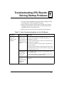
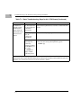
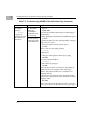
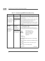
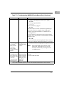
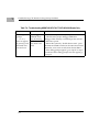
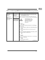
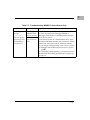
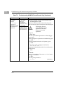
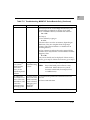
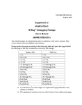
SBCTRBA/LT1
January 1996
Dear Valued Customer:
Thank you for your purchase of a Motorola Computer Group single board computer
(SBC) CPU (68K or 88K) board product.
This letter applies to the following families of CPU boards:
MVME147
MVME147S
MVME162
MVME162FX
MVME162LX
MVME166
MVME167
MVME176
MVME177
MVME187
MVME188
MVME188A
MVME197DP
MVME197LE
MVME197SP
If you have any trouble with your board, try the basic troubleshooting steps listed in
the following pages, before calling for help or sending your CPU board back for repair.
N ote
Wherever this letter mentions “this manual”, refer to the
User’s Manual or Installation Guide that came with your
board.
Once again, thank you for purchasing Motorola products. If you have any other
questions or comments, please contact your local Motorola Computer Group sales
representative.
Troubleshooting CPU Boards
2
ATroubleshooting CPU Boards:
Solving Startup Problems
T
❏
Try these simple troubleshooting steps before calling for help
or sending your CPU board back for repair.
❏
Some of the procedures will return the board to the factory
debugger environment. (The board was tested under these
conditions before it left the factory.)
❏
Selftest may not run in all user-customized environments.
Table T-1. Basic Troubleshooting Steps for ALL CPU Boards
Condition
Possible Problem Try This:
I. Nothing
works, no
display on the
terminal.
A. If the RUN or
PWR or +12V
LED is not lit, the
board may not
be getting correct
power.
1. Make sure the system is plugged in.
2. Check that the board is securely installed in its
backplane or chassis.
3. Check that all necessary cables are connected to the
board, per this manual.
4. Check for compliance with System Considerations,
per this manual.
5. Review the Installation and Startup procedures, per
this manual. In most cases, this includes a step-by-step
powerup routine. Try it.
B. If the LEDs are
lit, the board
may be in the
wrong slot.
1. For VMEmodules, the CPU board should be in the
first (leftmost) slot.
2. Also check that the “system controller” function on
the board is enabled, per this manual.
C.The “system
console”
terminal may be
configured
wrong.
Configure the system console terminal per this
manual.
T-1
T
Troubleshooting CPU Boards: Solving Startup Problems
Table T-1. Basic Troubleshooting Steps for ALL CPU Boards (Continued)
Condition
Possible Problem Try This:
II. There is a
display on the
terminal, but
input from the
keyboard and/or
mouse has no
effect.
A. The keyboard
or mouse may be
connected
incorrectly.
Recheck the keyboard and/or mouse connections and
power.
B. Board jumpers
may be
configured
incorrectly.
Check the board jumpers per this manual.
C. You may have
invoked flow
control by
pressing a HOLD
or PAUSE key, or
by typing
<CTRL>-S
Also, a HOLD
LED may be lit.
Press the HOLD or PAUSE key again.
If this does not free up the keyboard, type in
<CTRL>-Q
YOU ARE FINISHED (DONE) WITH THIS TROUBLESHOOTING PROCEDURE.
PROCEED WITH THE TROUBLESHOOTING PROCEDURE FOR YOUR PARTICULAR CPU
BOARD, AS GIVEN IN ONE OF THE FOLLOWING TABLES.
T-2
T
Table T-2. Troubleshooting MVME147 Series Boards Only
Condition
Possible Problem Try This:
III. Debug
prompt
A. Debugger
EPROM may be
missing.
147-Bug>
does not appear
at powerup, and
the board does
not auto boot.
B. The board
may need to be
reset.
1. Disconnect all power from your system.
2. Check that the proper debugger EPROM is installed
per this manual.
3. Reconnect power.
!
Caution
Performing the next
step will change some
parameters that may
affect your system
operation.
4. Restart the system by “double-button reset”: press
the RESET and ABORT switches at the same time; release
RESET first, wait five seconds, then release ABORT.
5. If the debug prompt appears, go to step IV. If the
debug prompt does not appear, go to step VI.
T-3
T
Troubleshooting CPU Boards: Solving Startup Problems
Table T-2. Troubleshooting MVME147 Series Boards Only (Continued)
Condition
Possible Problem Try This:
IV. Debug
prompt
A. The initial
debugger
environment
parameters may
be set wrong.
147-Bug>
appears at
powerup, but the
board does not
auto boot.
B. There may be
some fault in the
board hardware.
1. Type in
env;d <CR>
This sets up the default parameters for the debugger
environment.
2. When prompted to Update Non-Volatile RAM, type in
y <CR>
3. When prompted for clock speed (in MHz), change it
only if it is not correct.
4. When prompted to Reset System, type in
y <CR>
After a cold start, the debug prompt
147-Bug>
is displayed.
5. Change to the diagnostic directory by typing
sd <CR>
Now the prompt should be
147-Diag>
6. Run selftest by typing in
st <CR>
The tests take as much as 10 minutes, depending on
RAM size. They are complete when the prompt
returns. (The onboard selftest is a valuable tool in
isolating defects.)
7. The system may indicate that it has passed all the
selftests. Or, it may indicate a test that failed. If neither
happens, enter
de <CR>
Any errors should now be displayed. If there are any
errors, go to step VI. If there are no errors, go to step V.
T-4
T
Table T-2. Troubleshooting MVME147 Series Boards Only (Continued)
Condition
Possible Problem Try This:
V. The debugger
is in system
mode and the
board auto
boots, or the
board has passed
selftests.
A. No problems troubleshooting
is done.
No further troubleshooting steps are required.
VI. The board
has failed one or
more of the tests
listed above, and
can not be
corrected using
the steps given.
A. There may be
some fault in the
board hardware
or the on-board
debugging and
diagnostic
firmware.
1. Document the problem and return the board for
service.
2. Phone 1-800-222-5640.
Note
Even if the board passes all tests, it may
still be bad. Selftest does not try out all
functions in the board (for example, SCSI,
or VMEbus tests).
YOU ARE FINISHED (DONE) WITH THIS TROUBLESHOOTING PROCEDURE.
T-5
T
Troubleshooting CPU Boards: Solving Startup Problems
Table T-3. Troubleshooting MVME162 Series Boards Only
Condition
Possible Problem Try This:
III. Debug
prompt
A. Debugger
EPROM/Flash
may be missing
does not appear
at powerup, and
the board does
not auto boot.
B. The board
may need to be
reset.
1. Disconnect all power from your system.
2. Check that the proper debugger EPROM is installed
per this manual.
3. Remove jumper from J22, pins 9 and 10. This enables
use of the EPROM instead of the Flash memory.
4. Reconnect power. Restart the system.
5. If the debug prompt appears, go to step IV or step V,
as indicated. If the debug prompt does not appear, go
to step VI.
IV. Debug
prompt
A. The initial
debugger
environment
parameters may
be set wrong.
1. Start the onboard calendar clock and timer. Type
set mmddyyhhmm <CR>
where the characters indicate the month, day, year,
hour, and minute. The date and time will be displayed.
162-Bug>
162-Bug>
appears at
powerup, but the
board does not
auto boot.
B. There may be
some fault in the
board hardware.
!
Caution
Performing the next
step will change some
parameters that may
affect your system
operation.
2. Type in
env;d <CR>
This sets up the default parameters for the debugger
environment.
3. When prompted to Update Non-Volatile RAM, type in
y <CR>
4. When prompted to Reset Local System, type in
y <CR>
After a cold start, the debug prompt
162-Bug>
is displayed.
T-6
(continues>)
T
Table T-3. Troubleshooting MVME162 Series Boards Only (Continued)
Condition
Possible Problem Try This:
5. Change to the diagnostic directory by typing
sd <CR>
Now the prompt should be
162-Diag>
6. Run selftest by typing in
st <CR>
The tests take as much as 10 minutes, depending on
RAM size. They are complete when the prompt
returns. (The onboard selftest is a valuable tool in
isolating defects.)
7. The system may indicate that it has passed all the
selftests. Or, it may indicate a test that failed. If neither
happens, enter
de <CR>
Any errors should now be displayed. If there are any
errors, go to step VI. If there are no errors, go to step V.
V. The debugger
is in system
mode and the
board auto
boots, or the
board has passed
selftests.
A. No problems troubleshooting
is done.
No further troubleshooting steps are required.
VI. The board
has failed one or
more of the tests
listed above, and
can not be
corrected using
the steps given.
A. There may be
some fault in the
board hardware
or the on-board
debugging and
diagnostic
firmware.
1. Document the problem and return the board for
service.
2. Phone 1-800-222-5640.
Note
Even if the board passes all tests, it may
still be bad. Selftest does not try out all
functions in the board (for example, SCSI,
or VMEbus tests).
YOU ARE FINISHED (DONE) WITH THIS TROUBLESHOOTING PROCEDURE.
T-7
T
Troubleshooting CPU Boards: Solving Startup Problems
Table T-4. Troubleshooting MVME166/167/176/177/187/188/188A Boards Only
Condition
Possible Problem Try This:
III. Debug
prompt
A. Debugger
EPROM/Flash
may be missing
1xx-Bug>
does not appear
at powerup, and
the board does
not auto boot.
T-8
B. The board
may need to be
reset.
1. Disconnect all power from your system.
2. Check that the proper debugger EPROM or
debugger Flash memory is installed per this manual.
3. Reconnect power.
4. Restart the system by “double-button reset”: press
the RESET and ABORT switches at the same time; release
RESET first, wait seven seconds, then release ABORT.
5. If the debug prompt appears, go to step IV or step V,
as indicated. If the debug prompt does not appear, go
to step VI.
T
Table T-4. Troubleshooting MVME166/167/176/177/187/188/188A Boards Only (Continued)
Condition
Possible Problem Try This:
IV. Debug
prompt
A. The initial
debugger
environment
parameters may
be set wrong.
1xx-Bug>
appears at
powerup, but the
board does not
auto boot.
B. There may be
some fault in the
board hardware.
1. Start the onboard calendar clock and timer. Type
set mmddyyhhmm <CR>
where the characters indicate the month, day, year,
hour, and minute. The date and time will be displayed.
!
Caution
Performing the next
step will change some
parameters that may
affect your system
operation.
2. Type in
env;d <CR>
This sets up the default parameters for the debugger
environment.
3. When prompted to Update Non-Volatile RAM, type in
y <CR>
4. When prompted to Reset Local System, type in
y <CR>
5. After clock speed is displayed, immediately (within
five seconds) press the Return key
<CR>
or
BREAK
to exit to System Menu. Then enter a 3 “Go to System
Debugger” and Return
3 <CR>
Now the prompt should be
1xx-Diag>
(continues>)
T-9
T
Troubleshooting CPU Boards: Solving Startup Problems
Table T-4. Troubleshooting MVME166/167/176/177/187/188/188A Boards Only (Continued)
Condition
Possible Problem Try This:
6.You may need to use the cnfg command (see your
board Debugger Manual) to change clock speed
and/or Ethernet Address, and then later return to
env <CR>
and step 3.
7. Run selftest by typing in
st <CR>
The tests take as much as 10 minutes, depending on
RAM size. They are complete when the prompt
returns. (The onboard selftest is a valuable tool in
isolating defects.)
8. The system may indicate that it has passed all the
selftests. Or, it may indicate a test that failed. If neither
happens, enter
de <CR>
Any errors should now be displayed. If there are any
errors, go to step VI. If there are no errors, go to step V.
V. The debugger
is in system
mode and the
board auto
boots, or the
board has passed
selftests.
A. No problems troubleshooting
is done.
No further troubleshooting steps are required.
VI. The board
has failed one or
more of the tests
listed above, and
can not be
corrected using
the steps given.
A. There may be
some fault in the
board hardware
or the on-board
debugging and
diagnostic
firmware.
1. Document the problem and return the board for
service.
2. Phone 1-800-222-5640.
Note
Even if the board passes all tests, it may
still be bad. Selftest does not try out all
functions in the board (for example, SCSI,
or VMEbus tests).
YOU ARE FINISHED (DONE) WITH THIS TROUBLESHOOTING PROCEDURE.
T-10
T
Table T-5. Troubleshooting MVME197 Series Boards Only
Condition
Possible Problem Try This:
III. Debug
prompt
A. Debugger
EPROM/Flash
may be missing
197-Bug>
does not appear
at powerup, and
the board does
not auto boot.
B. The board
may need to be
reset.
1. Disconnect all power from your system.
2. Check that the proper debugger EPROM or
debugger Flash memory is installed per this manual.
3. Reconnect power.
4. Restart the system by “double-button reset”: press
the RESET and ABORT switches at the same time; release
RESET first, wait seven seconds, then release ABORT.
5. You will get a prompt asking if you want to continue
in debugger with double button reset (N/Y)? Type in
y <CR>
6. If the debug prompt appears, go to step IV or step V,
as indicated. If the debug prompt does not appear, go
to step VI.
T-11
T
Troubleshooting CPU Boards: Solving Startup Problems
Table T-5. Troubleshooting MVME197 Series Boards Only (Continued)
Condition
Possible Problem Try This:
IV. Debug
prompt
A. The initial
debugger
environment
parameters may
be set wrong.
197-Bug>
appears at
powerup, but the
board does not
auto boot.
B. There may be
some fault in the
board hardware.
1. Start the onboard calendar clock and timer. Type
set mmddyyhhmm <CR>
where the characters indicate the month, day, year,
hour, and minute. The date and time will be displayed.
!
Caution
Performing the next
step will change some
parameters that may
affect your system
operation.
2. Type in
env;d <CR>
This sets up the default parameters for the debugger
environment.
3. When prompted to Update Non-Volatile RAM, type in
y <CR>
4. When prompted to Reset Local System, type in
y <CR>
5. After clock speed is displayed, and the line
Idle MPU(s): xxxx
is displayed, immediately (within five seconds) press
the Return key
<CR>
or
BREAK
to exit to System Menu. Then enter a 3 “Go to System
Debugger” and Return
3 <CR>
Now the prompt should be
197-Diag>
(continues>)
T-12
T
Table T-5. Troubleshooting MVME197 Series Boards Only (Continued)
Condition
Possible Problem Try This:
6.You may need to use the cnfg command (see your
board Debugger Manual) to change clock speed
and/or Ethernet Address, and then later return to
env <CR>
and step 3.
7. Run selftest by typing in
st <CR>
The tests take as much as 10 minutes, depending on
RAM size. They are complete when the prompt
returns. (The onboard selftest is a valuable tool in
isolating defects.)
8. The system may indicate that it has passed all the
selftests. Or, it may indicate a test that failed. If neither
happens, enter
de <CR>
Any errors should now be displayed. If there are any
errors, go to step VI. If there are no errors, go to step V.
V. The debugger
is in system
mode and the
board auto
boots, or the
board has passed
selftests.
A. No problems troubleshooting
is done.
No further troubleshooting steps are required.
VI. The board
has failed one or
more of the tests
listed above, and
can not be
corrected using
the steps given.
A. There may be
some fault in the
board hardware
or the on-board
debugging and
diagnostic
firmware.
1. Document the problem and return the board for
service.
2. Phone 1-800-222-5640.
Note
Even if the board passes all tests, it may
still be bad. Selftest does not try out all
functions in the board (for example, SCSI,
or VMEbus tests).
YOU ARE FINISHED (DONE) WITH THIS TROUBLESHOOTING PROCEDURE.
T-13
T
Troubleshooting CPU Boards: Solving Startup Problems
T-14