1
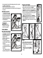
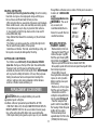
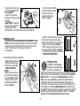
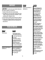
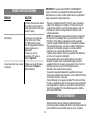
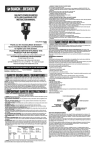
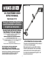
Model # LST136
36V LITHIUM TRIMMER / EDGER
INSTRUCTION MANUAL
Model Number LST136
Thank you for choosing Black & Decker! Go
to www.BlackandDecker.com/NewOwner
to register your new product.
PLEASE READ BEFORE RETURNING
THIS PRODUCT FOR ANY REASON:
If you have a question or experience a problem with your
Black & Decker purchase, go to
WWW.BLACKANDDECKER.COM/INSTANTANSWERS
for instant answers 24 hours a day.
If you canʼt find the answer or do not have access to the internet,
call 1-800-544-6986 from 8 a.m. to 5 p.m. EST Mon. - Fri
to speak with an agent.
Please have the catalog number available when you call.
KEY INFORMATION YOU SHOULD KNOW:
SAVE THIS MANUAL FOR FUTURE REFERENCE.
VEA EL ESPAÑOL EN LA CONTRAPORTADA.
POUR LE FRANÇAIS, VOIR LA COUVERTURE ARRIÈRE.
INSTRUCTIVO DE OPERACIÓN, CENTROS DE SERVICIO Y
PÓLIZA DE GARANTÍA. ADVERTENCIA: LÉASE ESTE
INSTRUCTIVO ANTES DE USAR EL PRODUCTO.
• The guard must be installed before trimming or edging - if
not, the motor will overheat (page 8).
• When replacing the line, use only .065 inch diameter
ROUND line (B&D Model #AF-100 is recommended) otherwise the tool will not function properly (page 11).
• Do not bump the feed head against the ground - it will
disrupt the feed mechanism.
1
TABLE OF CONTENTS
IMPORTANT SAFETY WARNINGS
AND INSTRUCTIONS
Safety Guidelines - Definitions .................................................2
Important Safety Warnings and Instructions ............................2
Components.............................................................................4
Important Safety Instructions for Battery Chargers ..................4
Important Safety Instructions for Battery Packs .......................5
Assembly / Adjustment.............................................................8
Operating Instructions ..............................................................9
Replacement Accessories........................................................10
Maintenance ............................................................................12
Troubleshooting .......................................................................12
Service Information ..................................................................13
Full Three-Year Home Use Warranty .......................................15
WARNING: When using electric gardening appliances, basic
safety precautions should always be followed to reduce risk of fire,
electric shock, and personal injury, including the following.
Read All Instructions
It is important for you to read and understand this manual. The
information it contains relates to protecting YOUR SAFETY and
PREVENTING PROBLEMS. The symbols below are used to help
you recognize this information.
SAFETY GUIDELINES - DEFINITIONS
DANGER: Indicates an imminently hazardous situation which,
if not avoided, will result in death or serious injury.
WARNING: Indicates a potentially hazardous situation which, if
not avoided, could result in death or serious injury.
CAUTION: Indicates a potentially hazardous situation which, if
not avoided, may result in minor or moderate injury.
NOTICE: Used without the safety alert symbol indicates a
potentially hazardous situation which, if not avoided, may result in
property damage.
2
• ALWAYS WEAR EYE PROTECTION – Wear safety spectacles
or goggles at all times when this tool is plugged in.
• GUARD – Do not use this tool without guard attached.
• DRESS PROPERLY – Do not wear loose clothing or jewelry.
They can be caught in moving parts. Rubber gloves and
substantial rubber soled footwear are recommended when
working outdoors. Donʼt operate the tool when barefoot or
wearing open sandals. Wear heavy long pants to protect your
legs. Wear protective hair covering to contain long hair.
• NYLON LINE – Keep face, hands and feet clear of rotating nylon
line at all times.
• THE ROTATING LINE PERFORMS A CUTTING FUNCTION –
Use care when trimming around screens and desirable plantings.
• KEEP ALL BYSTANDERS AWAY – at a safe distance from
work area, especially children.
• IMPORTANT WARNING – When being used as an Edger,
stones, pieces of metal and other objects can be thrown out at
high speed by the line. The tool and guard are designed to
reduce the danger. However, the following special precautions
should be taken:
• MAKE SURE that other persons and pets are at least 100 feet (30m) away.
• TO REDUCE THE RISK of rebound (ricochet) injury, work going
away from any nearby solid object such as wall, steps, large
stone, tree, etc. Use great care when working close to solid
objects and where necessary, do edging or trimming by hand.
• AVOID ACCIDENTALLY STARTING – Donʼt carry plugged-in
tool with finger on trigger.
• DO NOT FORCE THE TOOL – at a rate faster than the rate at
which it is able to cut effectively.
• USE THE RIGHT TOOL – Do not use this tool for any job except
that for which it is intended.
• DON’T OVERREACH – Keep proper footing and balance at all times.
• DAMAGE TO UNIT – If you strike or become entangled with a
foreign object, stop tool immediately, unplug, check for damage
and have any damage repaired before further operation is
attempted. Do not operate with a broken hub or spool.
• DISCONNECT TOOL – when not in use, when replacing line, or
prior to cleaning.
• AVOID DANGEROUS ENVIRONMENTAL CONDITIONS – Do
not use electric tools in damp or wet locations. Follow all
instructions in this Instruction Manual for proper operation of your
tool. Donʼt use the tool in the rain.
• DO NOT OPERATE portable electric tools in gaseous or
explosive atmospheres. Motors in these tools normally spark, and
the sparks might ignite fumes.
• STORE IDLETOOLS INDOORS – When not in use, tools should be
stored indoors in a dry, locked-up place out of reach of children.
• STAY ALERT – Do not operate this unit when you are tired, ill,
or under the influence of alcohol, drugs, or medication.
• MAINTAIN APPLIANCES WITH CARE – Follow instructions in
maintenance section. Keep handles dry, clean and free from oil
and grease.
• CHECK DAMAGED PARTS – Before further use of the
appliance, a guard or other part that is damaged should be
carefully checked to determine that it will operate properly and
perform its intended function. Check for alignment of moving
parts, binding of moving parts, breakage of parts, mounting, and
any other condition that may affect its operation. A guard or other
part that is damaged should be properly repaired or replaced by
an authorized service center unless otherwise indicated
elsewhere in this manual.
• DO NOT immerse tool in water or squirt it with a hose. DO NOT
allow any liquid to get inside it.
• DO NOT store the tool on or adjacent to fertilizers or chemicals.
• DO NOT clean with a pressure washer.
• Keep guards in place and in working order.
• Keep hands and feet away from cutting area.
WARNING: Do not use tool if the switch trigger does not turn
the tool on or off. Any tool that can not be controlled with the switch
trigger is dangerous and must be repaired.
SAVE THESE INSTRUCTIONS
The label on your tool may include the following symbols. The
symbols and their definitions are as follows:
V ..............volts
A ................amperes
Hz ............hertz
W................watts
min ............minutes
..............alternating current
no ..............no load speed
..........direct current
..............Class II Construction
............earthing terminal
............safety alert symbol
.../min ......revolutions or
reciprocations per minute
WARNING: Some dust created by this product contains
chemicals known to the State of California to cause cancer,
birth defects or other reproductive harm. Some examples of
these chemicals are:
• compounds in fertilizers
• compounds in insecticides, herbicides and pesticides
• arsenic and chromium from chemically treated lumber
To reduce your exposure to these chemicals, wear approved safety
equipment such as dust masks that are specially designed to filter out
microscopic particles.
3
IMPORTANT SAFETY INSTRUCTIONS
FOR BATTERY CHARGERS
COMPONENTS
SAVE THESE INSTRUCTIONS: This manual contains important
safety instructions for battery chargers.
• Before using charger, read all instructions and cautionary markings
on charger, battery pack, and product using battery pack.
5
2
1. On/Off Switch
6
2. Handle
WARNING: Shock hazard. Do not allow any liquid to get
4
inside charger.
1
3. Lock Off Button
CAUTION: Burn hazard. To reduce the risk of injury, charge
only designated Black & Decker batteries. Other types of batteries
may burst causing personal injury and damage.
3
4. Battery
CAUTION: Under certain conditions, with the charger plugged
in to the power supply, the charger can be shorted by foreign
material. Foreign materials of a conductive nature such as, but not
limited to, steel wool, aluminum foil, or any buildup of metallic
particles should be kept away from charger cavities. Always unplug
the charger from the power supply when there is no battery pack in
the cavity. Unplug charger before attempting to clean.
5. Charge Indicator
7
6. Power Command
8
7. Auxillary Handle
• DO NOT attempt to charge the battery pack with any chargers
other than the ones in this manual. The charger and battery
pack are specifically designed to work together.
• These chargers are not intended for any uses other than
charging designated Black & Decker rechargeable batteries.
Any other uses may result in risk of fire, electric shock or
electrocution.
• Do not expose charger to rain or snow.
• Pull by plug rather than cord when disconnecting charger.
This will reduce risk of damage to electric plug and cord.
• Make sure that cord is located so that it will not be stepped
on, tripped over, or otherwise subjected to damage or stress.
• Do not use an extension cord unless it is absolutely
WARNING:
8. Height Adjust
Locking Clamp
9. Trimmer Head
9
10. Edge Guide
11
11. Guard
10
12. Spool Housing
12
4
necessary. Use of improper extension cord could result in risk of
fire, electric shock, or electrocution.
• An extension cord must have adequate wire size (AWG or
American Wire Gauge) for safety. The smaller the gauge number
of the wire, the greater the capacity of the cable, that is 16 gauge
has more capacity than 18 gauge. When using more than one
extension to make up the total length, be sure each individual
extension contains at least the minimum wire size.
Recommended Minimum Wire Size for Extension Cords
center when service or repair is required. Incorrect reassembly
may result in a risk of electric shock, electrocution or fire.
• Disconnect the charger from the outlet before attempting any
cleaning. This will reduce the risk of electric shock. Removing the
battery pack will not reduce this risk.
• NEVER attempt to connect 2 chargers together.
• The charger is designed to operate on standard household
electrical power (120 Volts). Do not attempt to use it on any
other voltage.
Minimum Gauge for Cord Sets
Volts
Total Length of Cord in Feet
120V
0-25
26-50
51-100 101-150
240V
0-50
51-100 101-200 201-300
Ampere Rating
More Not more
American Wire Gauge
Than Than
0 - 6
18
16
16
14
6 - 10
18
16
14
12
10 - 12
16
16
14
12
12 - 16
14
12
Not Recommended
SAVE THESE INSTRUCTIONS
IMPORTANT SAFETY INSTRUCTIONS
FOR BATTERY PACKS
WARNING: For safe operation, read this manual and manuals
originally supplied with tool before using the charger.
The battery pack is not fully charged out of the carton. Before using
the battery pack and charger, read the safety instructions below.
Then follow charging procedures outlined.
• Do not place any object on top of charger or place the charger
on a soft surface that might block the ventilation slots and
result in excessive internal heat. Place the charger in a
position away from any heat source. The charger is ventilated
through slots in the top and the bottom of the housing.
• Do not mount charger on wall or permanently affix charger to
any surface. The charger is intended to use on a flat, stable
surface (i.e., table top, bench top).
• Do not operate charger with damaged cord or plug — have
them replaced immediately.
• Do not operate charger if it has received a sharp blow, been
dropped, or otherwise damaged in any way. Take it to an
authorized service center.
• Do not disassemble charger; take it to an authorized service
• Do not incinerate the battery pack even if it is severely
damaged or is completely worn out. The battery pack can
explode in a fire. Toxic fumes and materials are created when
battery packs are burned.
• Do not charge or use battery in explosive atmospheres, such
as in the presence of flammable liquids, gases or dust.
Inserting or removing the battery from the charger may ignite the dust
or fumes.
• If battery contents come into contact with the skin, immediately
wash area with mild soap and water. If battery liquid gets into the
eye, rinse water over the open eye for 15 minutes or until irritation
ceases. If medical attention is needed, the battery electrolyte for Liion batteries is composed of a mixture of liquid organic carbonates
and lithium salts.
READ ALL INSTRUCTIONS
5
• Contents of opened battery cells may cause respiratory irritation.
Provide fresh air.If symptoms persist, seek medical attention.
CHARGING PROCEDURE
The standard charger provided will charge a fully depleted battery in
about 2 hours.
1. Plug the charger into an appropriate outlet before inserting the
battery pack.
2. Insert the battery pack into the charger
A
as shown in figure A.
3. The green LED will flash
indicating that the battery is being
charged.
4. The completion of charge is
indicated by the green LED
remaining on continuously. The pack
is fully charged and may be used at
this time or left on the charger.
Recharge discharged batteries as soon
as possible after use or battery life may be greatly diminished.
WARNING: Burn hazard. Battery liquid may be flammable if
exposed to spark or flame.
• Charge the battery packs only in Black & Decker chargers.
• DO NOT splash or immerse in water or other liquids. This may
cause premature cell failure.
• Do not store or use the tool and battery pack in locations where
the temperature may reach or exceed 105°F (40˚C) (such as
outside sheds or metal buildings in summer).
WARNING: Never attempt to open the battery pack for any
reason. If battery pack case is cracked or damaged, do not insert into
charger. Do not crush, drop or damage battery pack. Do not use a
battery pack or charger that has received a sharp blow, been
dropped, run over or damaged in any way (i.e., pierced with a nail,
hit with a hammer, stepped on). Damaged battery packs should be
returned to service center for recycling.
CHARGER DIAGNOSTICS
This charger is designed to detect certain problems that can arise
with the battery packs or the power source. Problems are indicated
by one LED flashing in different patterns.
BAD BATTERY
The charger can detect a weak or damaged battery. The red
LED flashes in the pattern indicated on the label. If you see
this bad battery blink pattern, do not continue to charge the
battery. Return it to a service center or a collection site for
recycling.
HOT/COLD PACK DELAY
When the charger detects a battery that is excessively hot or
excessively cold, it automatically starts a Hot/Cold Pack
Delay, suspending charging until the battery has normalized.
After this happens, the charger automatically switches to the
Pack Charging mode. This feature ensures maximum battery
life. The red LED flashes in the pattern indicated on the label
when the hot / cold pack delay is detected.
WARNING: Fire hazard. Do not store or carry battery so that
metal objects can contact exposed battery terminals. For example, do
not place battery in aprons, pockets, tool boxes, product kit boxes, drawers,
etc., with loose nails, screws, keys, etc. Transporting batteries can possibly
cause fires if the battery terminals inadvertently come in contact with
conductive materials such as keys, coins, hand tools and the like. The
US Department of Transportation Hazardous Material Regulations (HMR)
actually prohibit transporting batteries in commerce or on airplanes (i.e.,
packed in suitcases and carry-on luggage) UNLESS they are properly
protected from short circuits. So when transporting individual batteries, make
sure that the battery terminals are protected and well insulated from materials
that could contact them and cause a short circuit. NOTE: Batteries should
not be put in checked baggage.
STORAGE RECOMMENDATIONS
1. The best storage place is one that is cool and dry away from
direct sunlight and excess heat or cold.
2. Long storage will not harm the battery pack or charger.
6
LEAVING THE BATTERY IN THE CHARGER
The charger and battery pack can be left connected with the green
LED glowing indefinitely. The charger will keep the battery pack
fresh and fully charged.
IMPORTANT CHARGING NOTES
1. Longest life and best performance can be obtained if the battery
pack is charged when the air temperature is between 60°F and
80°F (16°- 27°C). DO NOT charge the battery pack in an air
temperature below +40°F (+4.5°C), or above +105°F (+40.5°C).
This is important and will prevent serious damage to the battery
pack.
2. The charger and battery pack may become warm to touch while
charging. This is a normal condition, and does not indicate a
problem. To facilitate the cooling of the battery pack after use, avoid
placing the charger or battery pack in a warm environment such as
in a metal shed, or an uninsulated trailer.
3. If the battery pack does not charge properly:
a. Check current at receptacle by plugging in a lamp or other
appliance
b. Check to see if receptacle is connected to a light switch
which turns power off when you turn out the lights.
c. Move charger and battery pack to a location where the
surrounding air temperature is approximately 60°F - 80°F
(16° - 27°C).
d. If charging problems persist, take the tool, battery pack and
charger to your local service center.
4. The battery pack should be recharged when it fails to produce
sufficient power on jobs which were easily done previously. DO NOT
CONTINUE to use under these conditions. Follow the charging
procedure. You may also charge a partially used pack whenever
you desire with no adverse affect on the battery pack.
5. Foreign materials of a conductive nature such as, but not limited
to, steel wool, aluminum foil, or any buildup of metallic particles
should be kept away from charger cavities. Always unplug the
charger from the power supply when there is no battery pack in the
cavity. Unplug charger before attempting to clean.
6. Do not freeze or immerse charger in water or any other liquid.
WARNING: Shock hazard. Do not allow any liquid to get
inside charger. Never attempt to open the battery pack for any
reason. If the plastic housing of the battery pack breaks or cracks,
return to a service center for recycling.
STATE OF CHARGE INDICATOR (FIGURE B)
The battery is equipped with a state of charge indicator. This can be
used to display the current level of charge in the battery during use
and during charging. It does not
B1
indicate tool functionality and is subject B
to variation based on product
B2
components, temperature and enduser application.
Checking state of charge during use:
• Press the state of charge indicator
button (B1).
• The four LEDʼs (B2) will illuminate
indicating the percent of charge in
the battery. See chart in figure B.
• If LED light does not
illuminate,charge battery.
INSTALLING AND REMOVING THE BATTERY PACK
WARNING: Make certain the lock-off button is engaged to
prevent switch actuation before removing or installing battery.
TO INSTALL BATTERY PACK:
Insert battery pack into tool until
fully seated and an audible click is C
heard (figure C). Make sure
battery pack is fully seated and
fully latched into position.
TO REMOVE BATTERY PACK:
Depress the battery release button
in the back of the battery pack and
pull battery pack out of tool.
7
ATTACHING THE AUXILIARY HANDLE (FIGURES F AND G)
• Push the auxiliary handle
(F1) onto the tube (F2).
F
• Slide the bolt (G1) through
the holes in the auxiliary
F1
handle.
• Tighten the knob (G2) onto
the bolt by turning it
clockwise.
ASSEMBLY & ADJUSTMENT
WARNING: Before assembly, make sure that the tool is
switched off and the battery has been removed.
ASSEMBLY TOOLS REQUIRED (NOT SUPPLIED):
- Phillips Screwdriver
D
WARNING: Remove the
battery before attempting to
attach any of the following
components.
D2
F2
D1
ATTACHING THE GUARD
(FIGURES D AND E)
WARNING: NEVER
OPERATE TOOL
WITHOUT GUARD FIRMLY
IN PLACE. The guard must
always be properly attached
on the tool to protect the user.
• Remove the screw from
the guard.
• Keeping the guard square
to the trimmer head slide it
into place until the retaining
tab clicks into place (Ensure
that the guide rails (D1) on
the guard (D2) are correctly
aligned with the guide rails
(D3) on the trimmer head
(D4) (figure D).
• Secure the guard with the
screw (E1) (figure E).
D3
ADJUSTING THE POSITION OF THE AUXILIARY HANDLE
(FIG. G)
The auxiliary handle can be
adjusted to provide optimum G
balance and comfort.
• Loosen the knob on the
bolt by turning it counter
clockwise.
• Gently slide the auxiliary
handle up or down the tube
to the desired height.
• Tighten the knob onto the
bolt by turning it clockwise.
D4
E
E1
G2
8
G1
ADJUSTING THE HEIGHT OF THE TOOL (FIGURE H)
• This tool has a telescopic
mechanism, allowing you to
H
set it to a comfortable
height.
To adjust the height setting:
• Release the height adjust
locking clamp (H1).
• Gently pull the tube (H2)
up or down to the desired
height.
• Close the height adjust
locking clamp (H1).
H2
H1
RELEASING THE CUTTING LINE
In transit, the cutting line is taped to the spool housing.
• Remove the tape holding the cutting line to the spool housing.
OPERATING INSTRUCTIONS
WARNING: Always use proper eye protection that conforms
to ANSI Z87.1 (CAN/CSA Z94.3) while operating this power tool.
CAUTION: Inspect area to be trimmed and remove any wire,
cord, or string-like objects which could become entangled in the
rotating line or spool. Be particularly careful to avoid any wire which
might be bent outwardly into the path of the tool, such as barbs at the
base of a chain link fence.
9
SETTING THE TOOL TO TRIMMING OR EDGING MODE
(FIGURE I, J AND K)
• The tool can be used in trimming mode as shown in figure I or in
edging mode to trim overhanging grass along lawn edges and flower
beds as shown in figure K.
TRIMMING MODE
For trimming, the trimmer head
I
should be in the position shown in
I1
figure I. If it is not:
• Remove the battery from the tool.
• Press and hold the head release
button (I1).
• While holding the auxillary handle,
rotate the head clockwise.
• Release the head release button.
• Lift the edge guide (J1) into the
closed position.
Note: The head will only rotate in one
J
direction.
CAUTION: Wire edge guide
should only be used when in the
edging mode. Keep wire edge guide
in the retracted position when in the
trimming mode.
J1
EDGING MODE (FIGURE K)
For edging, the trimmer head should
be in the position shown in figure K.
If it is not:
K
• Remove the battery from the tool.
K1
• Press and hold the head release
button (K1).
• While holding the auxillary
handle, rotate the head
counterclockwise.
• Release the head release button.
K2
• Drop the edge guide (K2) in to
the open position. Ensure that the edging guide is all the way down,
an audible click will be heard.
Note: The head will only rotate in one direction.
Note: The Auto Feed System may not operate correctly if edge guide
is not used.
SWITCHING ON AND OFF
• To switch the tool on, press
L
in and hold the lock off button
(L1) then squeeze the trigger
lever (L2). Once the tool is
running you may release the
lock off button (L1).
L1
• To switch the tool off, release
the trigger lever.
WARNING: Never
attempt to lock the trigger
L2
lever in the on position.
POWER COMMAND MAX POWER / MAX RUNTIME
The max power / max runtime
feature (M1) is located on the
tool handle. It allows you to
optimize the tools
performance and boost the
power as needed.
• To choose max power to
tackle thick weeds, rotate dial
to setting 6.
• To choose max runtime to
increase battery life rotate dial
to setting 1.
• For a combination of both,
rotate dial to setting from 2 to 5.
M
OPERATING THE TRIMMER
• With the unit on, angle unit and slowly swing the
trimmer side to side as shown in figure N.
• Maintain a cutting angle of 5° to 10° as shown
in figure N1. Do not exceed 10°(figure N2). Cut
with the tip of the line. To keep distance from hard
surfaces use edge guide (10). Pull the guide out
until it snaps securely into place
• Maintain a minimum distance of 24 inches
(609.6 mm) between the guard and your feet as
shown in figure N3. To acheive this distance
adjust the overall height of the trimmer as shown
in figure H.
N1
M1
N2
N3
5 -10
O
O
EDGING
Optimum cutting results are achieved on
edges deeper than 2 inches (50 mm).
• Do not use the tool to create edges
or trenches.
• Guide the tool as shown in figure O.
• To make a closer cut, slightly tilt
the tool.
10
O
N
through Black & Decker service centers. To find your local service
location call: 1-800-544-6986
or visit
www.blackanddecker.com. P
WARNING: The use of
P2
Replacement
any accessory not
spool
recommended by Black &
Decker for use with this tool
Model #
could be hazardous.
HELPFUL CUTTING TIPS
• Use the tip of the string to do the cutting; do not force string
head into uncut grass. Use edge guide along such things as
fences, houses and flower beds for best practices.
• Wire and picket fences cause extra string wear, even breakage.
Stone and brick walls, curbs, and wood may wear string rapidly.
• Do not allow spool cap to drag on ground or other surfaces.
• In long growth cut from the top down and do not exceed 12
inches (304.8 mm) high.
• Keep trimmer tilted toward the area being cut; this is the best
cutting area.
• The trimmer cuts when passing the unit from the right to left.
This will avoid throwing debris at the operator.
• Avoid trees and shrubs. Tree bark, wood moldings, siding, and
fence posts can easily be damaged by the string.
AF-100
CUTTING LINE / LINE FEEDING
Your trimmer uses .065 inch (1.65 mm) diameter, ROUND
nylon line. During use, the tips of the nylon lines will become
frayed and worn and the special self feeding spool will
automatically feed and trim a fresh length of line. DO NOT BUMP
unit on ground in attempt to feed line or for any other purposes.
Cutting line will wear faster and require more feeding if the
cutting or edging is done along sidewalks or other abrasive
surfaces or heavier weeds are being cut.
REPLACEMENT ACCESSORIES
CAUTION: Before you begin trimming, only use the
appropriate type of cutting line.
Use Black & Decker replacement spool Model No. AF-100.
• USE ONLY .065 inch (1.65 mm) DIAMETER ROUND NYLON
MONOFILAMENT LINE. Do not use serrated or heavier gauge
line, as they will overload the motor and cause overheating.
• Other replacement parts (guards, spool caps, etc.) are available
11
REPLACING THE SPOOL
P1
(FIGURES P, Q AND R)
P1
• Remove battery from tool.
• Depress the tabs (P1) and
remove the spool cap (P2)
P3
from the spool housing (P3)
in the trimmer head (figure P).
• Replace spool with Black & Decker model # AF-100.
• Grasp empty spool with one hand and spool housing with other
hand and pull spool out.
• If lever (Q1) in base of
housing becomes dislodged, Q
replace in correct position
Q1
before inserting new spool
Q2
into housing.
• Remove any dirt and grass
from the spool and housing.
• Unfasten the end of the
cutting line and guide the line
into the eyelet (R2) figure R.
• Take the new spool and
push it onto the boss (Q2) in
the housing. Rotate the spool
slightly until it is seated.
The line should protrude
approximately 4-13/16 inches
(122mm) from the housing.
• Align the tabs on the spool
R
cap with the slots (R1) in the
housing (figure R).
• Push the cap onto the
housing until it snaps securely
into place.
CAUTION: To avoid tool
damage, if the cutting line
R1
protrudes beyond the
trimming blade, cut it off so that it just reaches the blade.
• Insert the 3/4 inch (19mm)
end of the bulk line into the T
hole (T1) in the spool
adjacent to the slot as
shown in figure T.
T1
R2
• Wind the cutting line onto the spool in
the direction of the arrow on the spool.
Make sure to wind the line on neatly and
in layers. Do not crisscross (figure U).
• When the wound cutting line reaches
the recesses (T2), cut the line. (figure T).
• Fit the spool onto the tool as described
in “REPLACING THE SPOOL”.
REWINDING SPOOL
(USE ONLY .065 IN. ROUND DIAMETER LINE) (FIGURES S,T & U)
NOTE: Hand wound spools from bulk line are likely to become
tangled more frequently than Black & Decker factory wound
spools. For best results, factory wound spools are
recommended.
To rewind spool, follow the steps below:
• Remove battery from tool.
• Remove the empty spool S
from the tool as described
in “REPLACING THE
SPOOL”.
• Make a fold at the end of
the cutting line at about 3/4
inch (19mm)(S1). Feed the
cutting line into one of the
line holding slots (S2) as
shown in figure S.
T2
U
THE RBRC™ SEAL
The RBRC™ (Rechargeable
Battery Recycling Corporation)
Seal on the Li-Ion battery (or
battery pack) indicates that the costs to recycle the battery (or battery
pack) at the end of its useful life have already been paid by Black &
Decker. RBRC™ in cooperation with Black & Decker and other
battery users, has established programs in the United States to
facilitate the collection of spent Li-Ion batteries. Help protect our
environment and conserve natural resources by returning the spent
Li-Ion battery to an authorized Black & Decker service center or to your
local retailer for recycling. You may also contact your local recycling center for
information on where to drop off the spent battery. RBRC™ is a registered
trademark of the Rechargeable Battery Recycling Corporation.
S1
S2
12
PROBLEM
MAINTENANCE
Automatic line feed does not
feed more line.
WARNING: To avoid serious injury, remove the battery from
the tool before performing any maintenance.
1. Keep the air intake slots clean to avoid overheating.
2. Your trimmer line can dry out over time. To keep your line in top
condition, store spare pre-wound spools or bulk line in a plastic,
sealable bag with a tablespoon of water.
3. Plastic parts may be cleaned by using a mild soap and a damp rag.
4. The line cutter on the edge of the guard can dull over time. It is
recommended you periodically touch-up the sharpness of the
blade with a file.
TROUBLE SHOOTING GUIDE
PROBLEM
Tool runs slowly.
Automatic line feed does not
feed more line.
SOLUTION
• Remove battery from tool.
• Check that the spool housing
can rotate freely. Carefully clean
it if necessary.
• Check that the cutting line
does not protrude more than
approximately 4-13/16 inches
(122mm) from the spool.
If it does, cut it off so that it just
reaches the line trimmingblade.
• More line is fed when the line
shortens to approximately 3
inches (76.2mm). To determine if
the line is not feeding, let line
wear past this point.
13
SOLUTION
• Keep the tabs depressed and
remove the spool from the spool
housing in the trimmer head.
• Ensure that the line is not
crisscrossed on the spool as
detailed in figure U. If it is,
unwind the cutting line, then
wind it back on the spool neatly
so that the lines do not cross.
• Inspect tracks at the bottom of
spool for damage. If damaged,
replace spool.
•Read the code on the back of
spool. If it reads “PA66” call
customer service for a replacement.
If it reads “ABS” this is not the issue.
• Pull the cutting line until it protrudes
approximately 4-13/16 inches
(122mm) from the spool. If
insufficient cutting line is left on the
spool, install a new spool of cutting line.
• Align the tabs on the spool cap
with the cut outs in the housing.
• Push the spool cap onto the housing
until it snaps securely into place.
• If the cutting line protrudes
beyond the trimming blade, cut
it off so that it just reaches the blade.
If the automatic line feed still does
not work or the spool is jammed, try
the following suggestions:
• Carefully clean the spool and
housing.
• Remove the spool and check if the
lever in the spool housing can
move freely.
IMPORTANT: To assure product SAFETY and RELIABILITY,
repairs, maintenance and adjustment should be performed by
authorized service centers or other qualified service organizations,
always using identical replacement parts.
TROUBLE SHOOTING CONTINUED
PROBLEM
SOLUTION
Overfeeding
• Ensure you are cutting with
the tip of the line (7 inches
(177.8mm) from the spool).
Use the edge guide if needed to
ensure proper space is
maintained.
• Ensure you are not
exceeding a 10° angle as
shown in figure N1.
Line unravels when cap or spool
is removed.
• Remove the spool and unwind
the cutting line, then wind it on
neatly again. Replace the spool
into the housing.
• Make sure to park the lines in
holding slots (S2) figure S
before removing.
•
•
•
•
This device complies with part 15 of the FCC rules. Operation is
subject to the following two conditions: (1) This device may not
cause harmful interference, and (2) this device must accept any
interference received, including interference that may cause
undesired operation.
NOTE: This equipment has been tested and found to comply with
the limits for a Class B digital device, pursuant to Part 15 of the
FCC Rules. These limits are designed to provide reasonable
protection against harmful interference in a residential installation.
This equipment generates, uses and can radiate radio frequency
energy and, if not installed and used in accordance with the
instructions, may cause harmful interference to radio
communications. However, there is no guarantee that interference
will not occur in a particular installation.
If this equipment does cause harmful interference to radio or
television reception, which can be determined by turning the
equipment off and on, the user is encouraged to try to correct the
interference by one or more of the following measures:
Reorient or relocate the receiving antenna.
Increase the separation between the equipment and receiver.
Connect the equipment into an outlet on a circuit different from that
to which the receiver is connected.
Consult the dealer or an experienced radio/TV technician for help.
Changes or modifications to this unit not expressly approved by the
party responsible for compliance could void the user's authority to
operate the equipment. This Class B digital apparatus complies
with Canadian ICES-003.
SERVICE INFORMATION
14
All Black & Decker Service Centers are staffed with trained
personnel to provide customers with efficient and reliable power tool
service. Whether you need technical advice, repair, or genuine
factory replacement parts, contact the Black & Decker location
nearest you. To find your local service location, refer to the yellow
page directory under "Tools—Electric" or call: 1-800-544-6986 or
visit www.blackanddecker.com
FULL THREE-YEAR HOME USE WARRANTY
Black & Decker (U.S.) Inc. warrants this product for three years
against any defects in material or workmanship. The defective
product will be replaced or repaired at no charge in either of two
ways:
The first, which will result in exchanges only, is to return the product
to the retailer from whom it was purchased (provided that the store is
a participating retailer). Returns should be made within the time
period of the retailerʼs policy for exchanges (usually 30 to 90 days
after the sale). Proof of purchase may be required. Please check
with the retailer for their specific return policy regarding returns that
are beyond the time set for exchanges.
The second option is to take or send the product (prepaid) to a Black
& Decker owned or authorized Service Center for repair or
replacement at our option. Proof of purchase may be required. Black
& Decker owned and authorized service centers are listed under
"Tools–Electric" in the yellow pages of the phone directory.
This warranty does not apply to accessories. This warranty gives you
specific legal rights and you may have other rights which vary from
state to state. Should you have any questions, contact the manager
of your nearest Black & Decker Service Center. This product is not
intended for commercial use.
LATIN AMERICA: This warranty does not apply to products sold in
Latin America. For products sold in Latin America, check country
specific warranty information contained in the packaging, call the
local company or see the website for warranty information.
FREE WARNING LABEL REPLACEMENT: If your warning labels
become illegible or are missing, call 1-800-544-6986 for a free
replacement.
Imported by
Black & Decker (U.S.) Inc.,
701 E. Joppa Rd.
Towson, MD 21286 U.S.A.
15
See ‘Tools-Electric’
– Yellow Pages –
for Service & Sales