1
i
T
G
4-1/2 in.
Double Insulated
Model No.
315.115080
Save this manuaU for
future reference
CALJ'[ION:
o Safety
o Features
Read and
follow aH Safety RuUes and
Operating hstructions
before
first use of this product.
Customer
o Operation
o Maintenance
o Parts List
HeUp Line: 1-800-932-3188
Sears, Roebuck and Co., 3333 Bevedy Rd., Hoffman
Visit the Craftsman Web page: www.sears.com/craftsman
Estates,
RL 60179
USA
US
983000-047
8-02
FULL ONE YEAR WARRANTY
ON CRAFT=_MRN ANGLE GRINDER
Ufthis I:RRF'[$MRN Angb Grinder falls to give compbte satisfaction within one year from the date of purchase,
RETURN IT TO THE NEAREST SEARS STORE IN THE UNITED STATES, and Sears will replace it, free of
charge.
Ufthis _:RAFTSMRN Angle Grinder is used for commercial or rental purposes, this warranty applies for only 90
days from the date of purchase.
This warranty gives you specific legal rights, and you may also have other rights which vary from state to state.
Sears, Roebuck and Co., Dept. 817 WA, Hoffman Estates, IL 60179
Your angle grinder has many features for making
grinding operations more pleasant and enjoyable.
Safety, performance and dependability have been
given top priority in the design of this angle grinder
making it easy to maintain and operate.
Look for this symbol to point
Your safety is involved.
out important
_
safety
CAUTmON: Carefully read through this entire
operator's manual before using your new angle
grinder. Pay close attention to the Rubs for Safe
Operation, Warnings and Cautions. If you use
your angle grinder properly and only for what it is
intended, you will enjoy years of safe, reliable
service.
precautions,
it means
attention!!!
WARNING:
The operation of any angle grinder can result in foreign objects being thrown
into your eyes, which can result in severe eye damage. Before beginning power tool
operation, always wear safety goggles or safety glasses with side shields and a full face
shield when needed. We recommend Wide Vision Safety Mask for use over eyeglasses or
standard safety glasses with side shields, available at Sears Retail Stores. Always wear eye
protection which is marked to comply with ANSI Z87.1.
WARNING:Readandunderstand
aH
instructions.
FailuretofollowaHinstructions
Hstedbebw,mayresuUt
in eUectric
shock,fire
and/orseriouspersonaU
injury.
WORKAREA
[] Keepyourworkareacleanandwet1tit. CUuttered
benchesanddarkareasinviteaccidents.
[] Donot operatepowertools in explosiveatmospheres,suchas in the presenceof flammable
liquids,gases,or dust.PowertooBmaycreate
sparkswhichmayignitethedustorfumes.
[] Keepbystanders,children,andvisitors away
whileoperatinga powertool. Distractions
can
causeyoutolosecontrol.
ELECTRICALSAFETY
[] Doubteinsulatedtoolsare equipped with a
poJadzed plug (one blade is wider than the
other). This plug will fit in a poJarized outlet onty
one way. if the ptug does not fit fully in the
outJet, reverse the pJug. If it still does not fit,
contact a qualified electrician to install a polarized outtet. Do not change the plug in any way.
Double insulation _'_ eliminates the need for the
three-wire grounded power cord and grounded
power supply system.
[] Avoid body contact with grounded surfaces, such
as pipes, radiators, ranges, and refrigerators.
There is an increased risk of electric shock if your
body is grounded.
[] Don't expose power tools to rain or wet condio
tions. Water entering a power tool will increase the
risk of electric shock.
[] Do not abuse the cord. Never use the cord to carry
the tooJs or pull the ptug from an outlet. Keep cord
away from heat, oH, sharp edges, or moving parts.
Replace damaged cords immediately. Damaged
cords increase the risk of electric shock.
Loose clothes, jewelry, or long hair can be caught in
moving parts.
[] Avoid
before
on the
switch
accidental starting. Be sure switch is off
pJugging in. Carrying tools with your finger
switch or plugging in tools that have the
on, invites accidents.
[] Remove adjusting keys or wrenches before
turning the tooJ on. A wrench or a key that is left
attached to a rotating part of the tool may result in
[] Do not overreach. Keep proper footing and
baJance at aH times. Proper footing and balance
enabbs better control of the tool in unexpected
situations. Do not use on a ladder or unstabb
supporL
[] Use safety equipment. AJways wear eye protection. Dust mask, nonskid safety shoes, hard hat, or
hearing protection must be used for appropriate
conditions.
TOOL
USE AND CARE
[] Use clamps or other practicaJ way to secure
and support the workpiece to a stable platform.
Holding the work by hand or against your body is
unstabb and may lead to loss of control.
[] Do not force toot. Use the correct toot for your
application. The correct tool will do the job better
and safer at the rate for which it is designed.
[] Do not use tool if switch does not turn it on or
off. Any tool that cannot be controlbd with the
switch is dangerous and must be repaired.
[] Disconnect the plug from power source before
making any adjustments,
changing accessories, or storing the tool Such preventive safety
measures reduce the risk of starting the tool
accidentally.
[] Store idle tooJs out of the reach of children and
other untrained persons. Tools are dangerous in
the hands of untrained users.
[] When operating a power tooJ outside, use an outdoor extension cord marked "W-A" or "W'. These
cords are rated for outdoor use and reduce the risk of
electric shock.
[] Maintain tooJs with care. Keep cutting tools
sharp and clean. Properly maintained tools with
sharp cutting edges are less likely to bind and are
easier to control.
PERSONAL
[] Check for misaJignment or binding of moving
parts, breakage of parts, and any other condio
tion that may affect the tooFs operation, if
damaged, have the tool serviced before using.
Many accidents are caused by poorly maintained
tools.
SAFETY
[] Stay abrt, watch what you are doing and use
common sense when operating a power tool
Do not use tooJ while tired or under the influo
ence of drugs, alcohoJ, or medication. A moment
of inattention while operating power tools may
result in serious personal injury.
[] Dress properly. Do not wear Joose clothing or
jeweJry. Contain Jong hair. Keep your hair,
clothing, and gloves away from moving parts.
[] Use only accessories that are recommended by
the manufacturer for your model. Accessories
that may be suitable for one tool, may become
hazardous when used on another tool.
SERVICE
[] TooJservicemustbe performed
only by qualio
fled repair personnel. Service or maintenance
performed by unqualified personnel could result in
a risk of injury.
[] When servicing a tooJ, use only identicaJ reo
pJacement parts. Follow instructions
in the
Maintenance section of this manual Use of
unauthorized parts or failure to follow Maintenance
hstrucfions may create a risk of eUectric shock or
injury.
[] AJways use proper guard with grinding wheet. A
guard protects operator from broken wheel fragments.
[] Dust and waste materials
[] Accessories must be rated for at Jeast the
speed recommended on the tool warning JabeL
Wheels and other accessories running over rated
speed carl fly apart and cause injury.
[] Do not enJarge or alter the center hote of the
grinding wheel as this could result in breaking it.
[] HoJd tool by insuJated gripping surfaces when
performing an operation where the cutting toot
may
contact hidden wiring or its own cord.
Contact with a "live" wire wiii make exposed metal
parts of the tool "live" and shock the operator.
[] Grinding wheet and guard must be securely
attached as described in this operating manual
before connecting the grinder to a power source.
[] Grinding
wheets must be stored in a dry pJace.
[] Before attaching the grinding wheel, inspect it
for visible defects. If cracked, chipped, or warped,
do not install it.
[] Do not overtighten the clamp nut on the grinding
wheek Excessive tightening carl cause the wheel
to crack during operation.
[] l_ake sure that the guard is in good condition
and securely installed before operating grinder.
[] Do not cJamp the grinder
fixed grinder.
in a vise or use as a
[] Never turn on the grinder with the grinding wheel
or any rotating parts touching the workpiece.
[] Use only grinding wheets in compliance with
ANSI standard B7.1 and rated greater than 11,000
RPM.
[] Do not use the grinder if the disc flange or
clamp nut is missing or if the spindle is bent.
[] AJways hotd the grinder securely with two
hands while working and at all times when it is
[] Never cover the air vents in the motor housing
with your hands while operating the grinder.
[] Notd the tooJ away from your body while it is
running. Keep your hands away from the abrasive
attachments.
should
not be
allowed to build up in the workshop.
sparks could start a fire.
[] Use onty the normaJ grinder surface.
the side or upper surfaces for cutting.
Hot metal
Never use
[] Keep the toot and its handte dry, cJean, and
free from oit and grease. Always use a clean
cloth when cleaning. Never use brake fluids,
gasoline, petrobum-based products, or any strong
solvents to clean your tool.
[] Knowyour power
tool Read operator's manuaJ
carefully. Learn its applications
and Hmitations,
as well as the specific potential hazards retated
to this tool Following this rub wHUreduce the risk
of eUectric shock, fire, or serious injury.
[] AJways wear safety gJasses. Everyday eye°
glasses have onJy impact-resistant
tenses; they
are NOT safety gJasses. Following this rule will
reduce the risk of serious personal injury.
[] Protect your tungs. Wear a face or dust mask if
the operation is dusty. Following this rule will
reduce the risk of serious personal injury.
[] Protect your hearing. Wear hearing protection
during extended periods of operation. Following
this rule will reduce the risk of serious personal
injury.
[] mnspect tool cords periodically and, if damaged,
have repaired at your nearest authorized sero
vice center. Constantly stay aware of cord
location. Following this rule will reduce the risk of
electric shock or fire.
[] Check damaged parts. Before further use of the
too!, a guard or other part that is damaged
shouJd be carefully checked to determine that it
wilt operate property and perform its intended
function. Check for alignment of moving parts,
binding of moving parts, breakage of parts,
mounting, and any other conditions that may
affect its operation. A guard or other part that is
damaged should be property repaired or reo
placed by an authorized service center. Following this rule will reduce the risk of shock, fire, or
serious injury.
[] Do not abuse cord. Never carry the tooJ by the
cord or yank it to disconnect it from the recepo
tacJe. Keep cord away from heat, oiJ, and sharp
edges. Following this rule will reduce the risk of
electric shock or fire.
[] Make sure your extension cord is in good
condition. When using an extension cord, be
sure to use one heavy enough to carry the
current your product will draw. A wire gage size
(A.W.G.) of at Jeast 1{} is recommended for an
extension cord 100 feet or Jess in Jength. A cord
exceeding 100 feet is not recommended.
If in
doubt, use the next heavier gage. The smaller
the gage number, the heavier the cord. An
undersized cord will cause a drop in line voltage
resulting in loss of power and overheating.
[] inspect for and remove aH naris from tumber
before grinding. Following this rule will reduce the
risk of serious personal injury.
[] Drugs, alcohol, medication. Do not operate tool
while under the influence of drugs, alcohol, or
any medication. Following this rule will reduce the
risk of electric shock, fire, or serious personal injury.
[] Keep hands away from grinding area. Following
this rule will reduce the risk of serious personal
injury.
[] Save these instructions.
Refer to them freo
quently and use them to instruct others who
may use this tool. If you loan someone this toot,
toan them these instructions
also.
WARNING:
Some dust created by power
sanding, sawing, grinding, drilling, and other
construction activities contains chemicals known
to cause cancer, birth defects or other
reproductive harm. Some examples of these
chemicals are:
" lead from lead-based
paints
" crystalline silica from bricks and cement and
other masonry products, and
" arsenic and chromium from chemicallytreated lumber.
Your risk from these exposures varies,
depending on how often you do this type of work.
To reduce your exposure to these chemicals:
work in a well ventilated area, and work with
approved safety equipment, such as those dust
masks that are specially designed to filter out
microscopic particles.
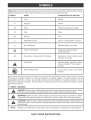
important: Some of the following symbols may be used on your tool. Please study them and barn their meaning.
Proper interpretation of these symbols wiii allow you to operate the tool better and safer.
SYMBOL
NAME
DESmGNATmON/EXPLANATmON
V
Volts
Voltage
A
Amperes
Current
Hz
Hertz
Frequency (cycles per second)
W
Watt
Power
Minutes
Time
Alternating Current
Type or a characteristic of current
No Load Speed
Rotational speed, at no load
Class H Construction
Designates double-insulated
construction tools
min
no
._/min
Revolutions or Reciprocation
Per Minute
Revolutions, strokes, surface speed,
orbits etc. per minute
Safety Alert
Undicates danger, warning or caution.
Utmeans attention!!! Your safety is
involved.
Wet Conditions Alert
Do not expose to rain or use in damp
locations.
The purpose of safety symbols is to attract your attention to possible dangers. The safety symbols, and the
explanations with them, deserve your careful attention and understanding. The safety warnings do not by
themselves eliminate any danger. The instructions or warnings they give are not substitutes for proper accident
prevention measures.
SYMBOL
MEANmNG
DANGER:
Failure
to obey a safety
warning
will result
serious shock
injury to
yourself
or toinjury.
others. Always
follow
the safety
precautions
to reduce
the risk
of fire,inelectric
and
personal
WARNmNG:
to obey
a safetytowarning
result
in serious
yourself
or to injury.
others.
Always follow Failure
the safety
precautions
reduce can
the risk
of fire,
electricinjury
shockto and
personal
CAU'NON:
Failure Always
to obey follow
a safety
may result toinreduce
property
or electric
personalshock
injuryand
to
yourself
or to others.
the warning
safety precautions
thedamage
risk of fire,
personal injury.
NOTE:
Advises you of information or instructions vital to the operation or maintenance of the equipment.
SAVE THESE iNSTRUCTiONS
4-1/2 in,
Grinding WheeU Capacity
Rating
120 VOLTS, 60 HZ, AC ONLY
No Load Speed
11,000 RPM
6,5
Amps
4.6 Ubs.
Net Weight
iNSTRUCTIONS
PACKING
With the exception of the side handb and accessory
wheeB, your angb grinder has been shipped
Angb Grinder with Guard
[] Carefully remove the grinder and accessories from
the box. Make sure that aH items Hsted in the
Wrench
packing Hst are included.
[] Unspect grinder carefully to make sure no breakage
or damage has occurred during shipping.
[] Do not discard the packing materiaU until you have
carefully inspected and satisfactorily operated
grinder.
LiST
Grinding Wheel (1)
Side Handle
Operator's Manual
,_
WARNING:
If any parts are missing, do not
operate this tool until the missing parts are
replaced. Failure to do so could result in possible
serious personal injury.
Before attempting to use your grinder, familiarize yourself with all operating features and safety requirements.
Make sure all grinding wheels and recommended accessories are in accordance with listed specifications for
this tool. For example, do not use grinding wheels that are rated at less than 11,000 RPM.
Use your grinder only for the purposes listed below.
[] Grinding metals.
[] Sanding wood or metal surfaces.
DOUBLEINSULATION
Doubleinsulationisa conceptin safetyin electric
powertools,whicheliminates
theneedfortheusual
three-wire
groundedpowercord.Allexposedmetal
partsareisolatedfromtheinternalmetalmotor
components
withprotectinginsulation.
Double
insulatedtoolsdo notneedto begrounded.
IMPORTANT:
Servicingofa toolwithdouble
insulationrequiresextremecareandknowledge
of the
systemandshouldbeperformedonlyby a qualified
servicetechnician.
Forservice,wesuggestyoureturn
thetooltoyournearestauthorized
servicecenterfor
repair.Alwaysuseoriginalfactoryreplacement
parts
whenservicing.
,_
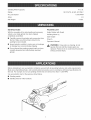
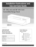
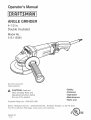
LOCK-ON
BUTTON
Your grinder also contains a lock-on feature that
allows you to lock the grinder on when you operate it
continuously for extended periods of time.
GUARD
A protective guard is provided on your grinder. It
deflects sparks and metal chips during use.
,A WARNING:
accompanied
Always use the guard that
the grinder. Comply with mounting
and use instructions and warnings found in the
manual for the grinder and ANSI B7.1. Failure to
heed these warnings can result in wheel
breakage and serious personal injury. For more
information on ANSI Standards, contact the
American National Standards Institute, Inc., 11
West 42nd Street, 13th Floor, New York, NY
10036.
WARNING:
The double insulated system is
intended to protect the user from shock resulting
from a break in the tool's internal wiring. Observe
all normal safety precautions to avoid electrical
shock.
SIDE HANDLE
ELECTRIC
MOTOR
The side handle provided, stabilizes your grinder and
must be used during all operations. In addition to
maintaining safe control during use, the side handle
also provides convenient ease of operation for the
operator.
Your grinder has a precision built electric motor. It
should be connected to a power supply that is 120
volts, 60 Hz, AC only (normal household current). Do
not operate this tool on direct current (DC). A voltage
drop of more than 10 percent will cause a loss of
power and the motor will overheat. If your tool does
not operate when plugged into an outlet, doublecheck the power supply.
TRIGGER
SPINDLE
LOCK
BUTTON
The spindle lock button secures the spindle so that
only one wrench is needed to change the grinding
wheel.
SWITCH
Your grinder has a conveniently located trigger switch.
SPINDLE
LOCK BUTTON
LOCK-ON
BUTTON
TRIGGER
SWITCH
SIDE HANDLE
GRINDING
WHEEL
GUARD
Fig. 1
8
WARNING:YourgrindershouUd
neverbe
connectedtopowersuppUy
whenyouare
assemblingparts,makingadjustments,
installing
or repUacing
accessory
wheeB,cbaning,or when
notin use,Disconnecting
thegrinderwHU
prevent
accidentaU
startingthatcouUd
causeserious
personaU
injury,
JNSTALUNGSiDEHANDLE
Follow these directions when installing accessory
wheels.
[] Unplug your grinder.
WARNING:
Failure to unplug your grinder could
result in accidental starting causing serious
injury.
NOTE: Your grinder is shipped with the disc flange
and clamp nut attached to the spindle.
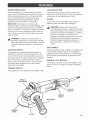
See Figure 2.
Follow these directions when installing the side
handle.
[] Depress spindle lock button and rotate clamp nut
until spindle locks. To prevent damage to the
spindle or spindle lock, always allow motor to come
to a complete stop before engaging spindle lock.
[] Unplug your grinder.
WARNING:
Failure to unplug your grinder could
result in accidental starting causing serious
[] Unstall the side handle by screwing it into the side
of the gear housing.
NOTE: You can install the handle on either the left
or right side of the grinder, depending on operator
preference. It must always be used to prevent loss
of control and possible serious injury.
[] Tighten side handle securely.
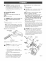
[] Loosen and remove clamp nut from spindle. Do
not remove disc flange.
[] Make sure fiats on the bottom of disc flange are
engaged with fiats on spindle.
[]
To instaii grinding whee/: Place grinding wheel over
the spindle. Thread the clamp nut on the spindle
with the fiat side of nut facing up. Fit raised, small
diameter portion of the clamp nut into the hob in the
wheel and finger tighten. See Figure 3a.
WARNING:
Always install grinding wheel with
the depressed center against the disc flange.
Failure to do so will cause the grinding wheel to
crack when tightening the clamp nut. This could
result in serious personal injury because of loose
particles breaking off and being thrown from the
grinder. Do not overtighten.
GEARHOUSING
TO
_a_ TIGHTEN
SIDEHANDLE
iNSTALLiNG
ACCESSORY
Fig. 2
WHEELS
See Figures 3a and 3b.
,_
WARNING:
Thoroughly inspect a new grinding
wheel before you install it on the grinder.
o Tap lightly around the wheel using a wooden
hammer.
TO
LOOSEN
WRENCH
CLAMP
NUT
GRINDING
WHEEL,
DBC
FLANGE
o Listen carefully to the resulting sounds.
Places with fissures or cracks will result in a
different sound.
Do not use a wheel containing fissures or
cracks.
When you install a new grinding wheel, carry out
a no load revolution test of approximately one
minute with the grinding wheel facing a safe
direction, i.e., away from people or objects.
Fig. 3a
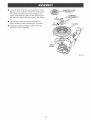
[]
To install optional flap disc (sold separately): PHace
flap disc over the spindHe. Thread the champ nut on
the spindHe with the fiat side of nut facing up. Fit
raised, smaHHdiameter portion of the champ nut into
the hoHein the wheeH and finger tighten. See Figure
3b.
INCORRECTLY
CLAMP NUTPLACED
(_
CLAMP NUT
PLACEDCORRECTLY
TO
TIGNTE_
[] Depress the spindHe Hockbutton and rotate the
wheeH cHockwise unfiHthe spindHe Hocks in position.
LoToOEN__
/
FLAP D,SC
[] Tighten the champ nut secureHy with the wrench
provided. Do not overfighten.
DiSC
FLANGE
Fig. 3b
10
_
WARNmNG:
Beforeconnecting
yourgrinderto
powersupply,alwayschecktobesureswitchis
notin tockoonposition.Failuretodoso could
resultinaccidentalstartingofyourgrinder
resultinginpossibleseriousinjury.
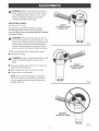
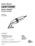
ADJUSTINGGUARD
CORRECT
LOCATIONOF GUARD
(HANDLELEFT)
See Figures 4, 5, and 6,
The guard on your grinder should be correctly
installed depending on which side the handle is
mounted. Never use your grinder without the guard
correctly in pJace.
_
WARNING:
Never place the guard so that it is
on front of the grinder as shown in Figure 6. This
could result in serious injury because sparks and
loose particles thrown from the grinding wheel
would be directed toward the operator. Always
place the guard in the correct location as shown.
Fig. 4
Follow these directions when adjusting the guard.
[] Unplug your grinder.
,_
WARNING:
Failure to unplug your grinder could
result in accidental starting causing serious
CORRECT
LOCATIONOFGUARD
(HANDLERIGHT)
[] Loosen the clamp screw until you can remove the
guard from the bearing cap.
[] Rotate guard to its correct position as shown.
[] Tighten clamp screw securely.
NOTE: Be sure the raised ridge on the guard is
seated in the groove on the bearing cap. Never
use your grinder without the guard in place and
Fig. 5
INCORRECT__
LOCATIONOF GUARD
1
Fig. 6
11
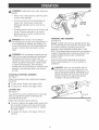
,_ WARNING:Followtheserubswhenusingyour
grinder.
Alwayswearsafetyglassesandkeepguard
in placewhengrinding.
o Hotmetalsparksfrommetalgrindingcan
causea fire.Avoidsparkcontactwith
flammablematerialssuchas sawdustor
clothing.
o Grindingwheelsmustbefreeof fissuresand
cracks.Fissuresandcrackscancausea
grindingwheelto shatterresultingin possibleseriousinjury.
TRIGGER
SWITCH
Fig. 7
GRINDING
_
,_
DANGER:Neverattacha woodcuttingor
carvingbladeofanytypetothisanglegrinder.It
is onlydesignedforgrindingandsanding.Use
foranyotherpurposeis notrecommended
and
createsa hazard,whichwiiiresultin serious
AND SANDING
See Figure 8.
AJways carefully select and use grinding wheels that
are recommended for the material to be ground. Make
sure that the minimum operating speed of any
accessory wheel selected is not less than 11 ,BOO
RPM The grinding wheel provided with your grinder is
suitable for grinding welds, preparing surfaces to be
welded, grinding structural steel, and grinding
stainless steel
WARNING:
Do not attempt to operate this tool
until you have read thoroughly and understand
completely all instructions, safety rubs, etc.
contained in this manual. Failure to comply can
result in accidents involving fire, electric shock,
or serious personal injury. Save operator's
manual and review frequently for continuing safe
operation, and instructing others who may use
this took
STARTmNG/STOPPmNG
LOCK-ON
BUTTON
Secure all work before beginning any operation.
Secure small workpieces in a vise or clamp to a
workbench.
_
GRINDER
See Figure X
DANGER:
Never use your grinder with the
guard removed. It has been designed for use
only with the guard installed. Attempting to use
grinder with guard removed will result in loose
particles being thrown against the operator
resulting in serious personal injury.
Follow these directions when starting and stopping
the grinder.
[]
To start grinder: Depress the trigger switch.
[]
To stop grindet_ Release the trigger switch.
LOCKING
ON
See Figure 7.
Your grinder has a lock-on feature that is convenient
when you operate the grinder continuously for
extended periods of time.
5° to 15°
Fig. 8
Follow these directions when locking on.
[]
To lock-on: Depress the trigger switch, push in the
lock-on button located on the side of the handle,
then while holding the lock-on button in, release
the trigger switch.
[]
To release lock: Depress the trigger switch and
release it.
12
Thekeytoefficientoperationbeginsbycontrollingthe
pressureandsurfacecontactbetweenthegrinding
wheeU
andworkpiece,FUat
surfacesaregroundat an
acuteangUe,
normallybetween5 to 15degrees,
FormaximumcontroU,
hoUd
thegrinderinfrontand
awayfromyouwithbothhands,keepingthegrinding
wheeU
dearoftheworkpiece,
Startyourgrinderand
Uetthe motorandgrindingwheeU
builduptofullspeed,
GraduallyUower
grinderuntilthegrindingwheeU
contactstheworkpiece,
ForbestresuUts
keepthegrinderflutedatanangUe
from5 to 15degreesandconfinuousUy
movingata
steady,consistentpace,Movethegrinderbackand
forthor upanddownovertheworkarea,Keepthe
grindermovingso thatanexcessiveamountof
materiaU
is notremovedfromonearea,Rfthegrinder
is heldin onespottoolong,it willgougeandcut
groovesintheworkpiece,If thegrinderis heldattoo
sharpanangle,itwillalsogougetheworkpiece
becauseofconcentration
ofpressureona smallarea,
Usejust enoughpressuretokeepthegrinderfrom
chatteringor bouncing,Heavypressurewilldecrease
itsspeedandputa strainonthemotor,Normallythe
weightofthetoolaloneis adequateformostgrinding
jobs,Uselightpressurewhengrindingjaggededges
or looseboltswherethereis thepotentialforthe
grinderto snagonthemetaledge,
Liftthegrinderawayfromtheworkpiece
before
turningyourgrinderoff,
13
A
TO
TIGHTEN
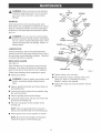
WARNING:WhenservicinguseonUy
idenficaU
CraftsmanrepUacement
parts.Useofanyother
partsmaycreatea hazardor causeproduct
damage.
CLA_IP
GENERAL
AvoidusingsoUvents
whenchartingpUastb
parts.
MostpUastbs
aresuscepfiMe
todamagefromvarious
typesofcommerdaU
soUvents
andmaybedamaged
bytheiruse.Usedeanclothstoremovedirt,carbon
dust,etc.
,_
WRENCH
GRINDING
WHEEL
WARNmNG: Do not at any time Uetbrake fluids,
gasoline, petrobum-based products, penetrating
oils, etc. come in contact with pUastb parts. They
contain chemicaB that can damage, weaken, or
destroy pUasfic.
DISC
FLANGE
GUARD
LUBRICATION
AH of the bearings in this tooUare Uubrbated with a
sufficient amount of high grade hJbricant for the life of
the unit under normal operating conditions. Therefore,
no further hJbrication is required.
REPLACmNG
CLAMP
SCREW
SPINDLE
GUARD
See Figure 9.
After extended use, the guard may wear and need
replacing. If you drop your grinder and damage the
guard it may also be necessary for you to replace it.
BEARINGCAP
Fig. 9
Follow these directions when replacing the guard.
[] Tighten clamp screw securely.
[] Unplug your grinder.
[]
,A
FLATS
WARNING:
Failure to unplug your grinder could
result in accidental starting causing serious
Reassemble disc flange, grinding wheel, and
clamp nut. Refer to °qnstalling Accessory
Wheels" earlier in this manual.
[] Tighten the clamp nut securely with the wrench
provided.
[] Depress spindle lock button and rotate clamp nut
until spindle locks.
[] Loosen and remove clamp nut from spindle using
the wrench provided.
[] Remove grinding wheel and disc flange.
[] Loosen the clamp screw until you can remove the
guard from the bearing cap.
[] Place the new guard on the shoulder of the
bearing cap.
NOTE: If the new guard will not fit, loosen the
clamp screw until they slide over the bearing cap.
[] Rotate guard to the correct position as shown.
NOTE: Be sure the raised ridge on the guard is
seated in the groove on the bearing cap.
14
Keepthecordawayfromthework
_, CAUTmON:
areaandpositionthecordsothatitwHH
notbe
caughton materiaisor otherobjectsduring
grinding.
EXTENSIONCORDS
Whenusinga powertooiata considerabie
distance
fromthepowersource,useanextensioncordheavy
enoughtocarrythecurrentthatthetooiwHidraw.An
undersized
extensioncordwHicausea dropin Hne
voitage,resuifingin a Hess
of powerandcausingthe
motorto overheat.Usethechartprovidedbelowto
determine
the minimumwiresizerequiredinan
extensioncord.Onlyuseroundjacketedcordslisted
by Underwriter's
Laboratories
(UL).
Lengthof ExtensionCord WireSize(A.W.G.)
Upto25
16
26to50
14
51to 100
12
Whenworkingwiththetooioutdoors,usean
extensioncordthatis designedforoutsideuse.This
is indicatedby theiettersWAonthecord'sjacket.
Beforeusingan extension
cord,inspectit forboseor
exposedwiresandcutor worninsulafion.
A
WARNING:Checkextensioncordsbeforeeach
use.If damagedreplaceimmediately.
Neveruse
toolwitha damaged
cordsincetouchingthe
damagedareacouldcauseelectricalshock
resultingin seriousinjury.
A
WARNmNG:
Alwayswearsafetygogglesor
safetyglasseswithsideshieldsduringpower
tooloperationor whenblowingdust.Ifoperation
isdusty,alsoweara dustmask.
Thefollowingrecommended
accessories
arecurrecnlyavailableatSearsRetailStores.
[] GrindingWheels
[] FlapDiscs
[] SandingKits
,_
WARNING:Theuseofattachments
or accessories
notlistedmightbehazardous.
15
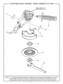
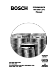
CRAFTSMAN
ANGLE
GFiJNDER - MODEL NUMBER
315.115080
SEE NOTE'A"
2
3
4
5
7
NOTE: "A" o The assembJy sSown represents an important part of the Double lnsuJated System. To avoid
the possibility of alteration or damage to the System, service shouJd be performed by your nearest Sears Repair Center. Contact your nearest Sears Retail Store for Service Center information.
16
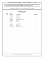
CRAFTSMAN
ANGLE
GRINDER-
MODEL NUMBER
315.115080
J
The
number wiii regarding
be found on
a plate
attached
to the or
motor
housing.
Always
in
aiimodel
correspondence
your
ANGLE
GRINDER
when
ordering
repairmention
parts. the model number 1
SEE BACK
PAGE FOR PARTS
ORDERING
iNSTRUCTiONS
PARTS LiST
Key
No.
Part
Number
Description
1
6917311
Data Plate
1
2
6832535
Side Handle
1
3
6922279
Logo Plate
1
4
9020516
5
6020249
Guard
1
6
6940622
Disc Flange
1
7
6681953
Grinding Wheel
1
8
6940693
Clamp Nut
1
9
6241770
Wrench
1
983000-047
Operator's Manual
1
Quantity
* Clamp Screw (MS X 16)
* Standard
Hardware item o May Be Purchased
17
1
Locally
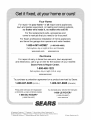
Your Home
For repair-in
your home-of
all major brand appliances,
lawn and garden equipment, or heating and cooling systems,
no matter who made it, no matter who sold it!
..................
For the replacement parts, accessories and
owner's manuals that you need to do-it-yourself.
..................
For Sears professional installation of home appliances
and items like garage door openers and water heaters.
..................
1-8 00-4-MY-H 0 ME® (1-800-469-4663)
oa,,
an t, o, o,oht sod
Oaoada
www.sears.com
..........
www.sears.ca
Our
Home
For repair of carry-in items like vacuums, lawn equipment,
and electronics, call or go on-line for the location of your nearest
Sears Parts & Repair Center.
1-800-488-1222
Call anytime,
day or night (U.S.A. only)
www.sears.com
To purchase a protection
1-800-827-6655
Pard pedir servicio
..................
agreement
on a product serviced
(U.S.A.)
1-800-361-6665
de reparacien
Au Canada
a domicilio, y pard ordenar piezas.
1-888-S U-HOGAR sM
by Sears:
(Canada)
pour service en frangais:
1 -800- LE- FO YER Mc
(1-800-533-6937)
(1-888-784-6427>
www.sears.ca
...............
SEARS
® Registered
Trademark
/ TMTrademark
/
SM
Service
Mark of Sears,
Roebuck
® Marca Registrada
/ TM Marca de F_brica / SM Marca de Servicio
de Sears,
MC
Marque
de commerce
/ MD Marque
d6pos6e
de Sears,
Roebuck
and Co.
and Co.
Roebuck
and
Co.
® Sears,
Roebuck
and Co.