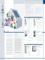
1
2| Steca Elektronik GmbH | 87700 Memmingen | Germany | Fon +49 (0) 8331 8558-0 | Fax +49 (0) 8331 8558-132 | www.stecasolar.com www.stecasolar.com PV GRID CONNECTED 4-17 Grid Connected Inverter: Technology 6 StecaGrid 300/500, StecaGrid Control StecaGrid Remote PV GRID CONNECTED PV OFF GRID 8 StecaGrid 2000+ 10 StecaGrid Connect: User Software for Remote Monitoring 13 StecaGrid Configurator 13 Steca AJ 58 Steca XPC 59 Steca Compact 60 Steca HPC 61 Xtender XTH 3,000 W - 8,000 W 62 SOLAR THERMAL 64-93 Solar Thermal Systems: Technology 66-67 Connection examples for DC disconnect 14 Temperature Differential Controller: Service Information 16 Steca TR 0201 68 Product Overview 17 Steca TR 0301 69 Steca TR 0301 U 70 Steca TR 0301sc 71 Steca Sundra 72 Steca Suntana 73 Steca Suntana 2 74 Steca TR 0502 76 Steca TR 0603 78 Steca TR 0603mc 80 Steca Solsum 5.0c, 8.0c, 6.6c, 8.8c, 10.10c 27 Steca TR 0704 82 Steca PR 1010, 1515, 2020, 3030 28 Steca TA 0403 84 Steca 2020-IP (Version IP 65) 29 PV OFF GRID 18-63 Solar Home Systems 20 Night Light Systems 22 Steca‘s Charging Technology 24 Solar Charge Controller: Steca PR 0303, PR 0505 26 Steca Solarix Alpha, Gamma, Sigma, Omega 30 Steca Solarix PRS 31 Steca PR 0606N, PR 1010N Night 32 Steca Solarix 2401, 4401 33 Steca Tarom 235, 245, 440 34 Steca Power Tarom 2070, 2140, 4055, 4110, 4140 35 Content Accessories: Steca PA Tarcom Data Logger 36 Steca PA HS200 Shunt 37 Steca PA 15 Remote Control 38 Steca PA EV 200 DC Relay 38 Solar Stations: Steca Solsum VC Voltage Converter 39 Steca TPS 20 86 MDC/MDCI DC-DC Voltage Converter 40 Steca TPS 25 88 Energy Saving Lamps: SOLAR THERMAL STECA – T H E C O M PA N Y Steca Solsum ESL 5 W, 7 W, 11 W/12 V Energy Saving Lamps Accessories: 41 Solar freezer: Steca PF 166 42 Fuel Cells: Steca fuel cells Efoy 600, 1200, 1600 Steca Elektronik GmbH reserves the right to add, modify or discontinue products which are shown in the catalogue. Please return to Steca if you need further and updated product information. The information contained in this catalogue is not comprehensive. Despite our efforts, it may not be accurate, up to date or applicable to the circumstances of any particular case. We cannot accept any liability for any inaccuracies or omissions in this catalogue. Steca is a protected trademark of Steca Elektronik GmbH, Germany, registered by the International Bureau of the World Intellectual. You may not use this trademark without our express permission. Your use of this catalogue and the operation of these terms and conditions shall be governed in accordance with the laws of the Federal Republic of Germany. 90 Steca TA VM2 91 Steca TA ES1 92 Steca TA OP1 92 Temperature sensors: 43 Steca Pt 1000 93 44 Steca Pt 1000-RAF 93 Hybrid System 46 Steca Pt 1000-MWT 93 General Recommendations 50 STECA – THE COMPANY Steca Solsafe 52 Solar electronics – made by Steca Inverter Selection Matrix 51 30 years of Steca Electronics PV Battery Systems Disclaimer Steca TA VM1 Steca – The EMS provider Sine Wave Inverter: 94-103 96 98 100 Steca Solarix PI 550 W - 2,200 W 54 Service about the theme electronic 102 Steca Solarix Sinus 550 I, 550 RI, 900 I, 900 RI Regional and international 104 57 Symbol-Legend 106 |3 4|4| Steca Elektronik GmbH | 87700 Memmingen | Germany | Fon +49 (0) 8331 8558-0 | Fax +49 (0) 8331 8558-132 | www.stecasolar.com |5 PV GrID CoNNeCTeD Power from the sun... ... for everyday use In one hour, the amount of energy radiated to the earth by the sun exceeds the annual energy requirement of the world population. Making use of this inexhaustible energy source for our everyday electricity requirement is the great challenge of the present and the future. Steca was quick to recognise the potential of solar energy: The company has become synonymous all over the world with vision, innovation, and initiative in the name of solar power. Steca is a recognised specialist in the development of high-performance systems which turn light into electricity before feeding it into the public grid. To achieve this, Steca has developed modular components which offer made-to-measure solutions for the widest range of household sizes and demands. Whether being used in a small solar power system for a single-family house or an elaborate combined solution for an industrial complex, Steca grid-feed inverters all have one thing in common: They offer the highest performance along with maximum flexibility and ease of use. PV GrID CoNNeCTeD CoNNeCTeD PV GrID CoNNeCTeD MiniString-Inverter for small solar systems Communication unit for MiniString-Inverter Steca DualString-Inverter for solar systems from 2,000 W Communication unit for DualString-Inverter 6|6| Steca Elektronik GmbH | 87700 Memmingen | Germany | Fon +49 (0) 8331 8558-0 | Fax +49 (0) 8331 8558-132 | www.stecasolar.com |7 PV GrID CoNNeCTeD G A E D F B C legende: A B C D E F G Generator Inverter Electricity meter for injection House connection point Public electricity network Electricity meter for consumption Consumer load PV GrID CoNNeCTeD Inverters for grid connection Together with their range of accessories, the StecaGrid inverters represent an innovative family of inverter solutions for grid-connected solar power systems. With a combination of the highest possible performance, ease of use and maximum flexibility, Steca offers a range of modular components that you can combine to suit your requirements – solutions from 300 W to several 10,000 W. This combination of an enormous range of system sizes, a modular concept and a wide range of accessories offers you over 100 different possibilities for designing an inverter system tailored to your individual needs. Maximum flexibility for maximum results. Example for configuration of a 4,4 kWp system: Module type: 185 Wp (Umpp = 36,0 V; Impp = 5,1 A) Module quantity: 24 Inverter: StecaGrid 2000+ Number of inverters: 1 Master, 1 Slave Number of MPP trackers: 4 Modules per inverter: 2x6 Installed nominal power: 4,4 kWp (DC) kWh 8| Steca Elektronik GmbH | 87700 Memmingen | Germany | Fon +49 (0) 8331 8558-0 | Fax +49 (0) 8331 8558-132 | www.stecasolar.com |9 Steca Elektronik GmbH | 87700 Memmingen | Germany | Fon +49 (0) 8331 8558-0 | Fax +49 (0) 8331 8558-132 | www.stecasolar.com PV GrID CoNNeCTeD PV GrID CoNNeCTeD Inv e r t e r Inverter Technical data StecaGrid 300 StecaGrid 500 176 71 Input DC Input voltage range 45 V – 135 V 45 V – 230 V MPPT range 45 V – 100 V 75 V – 170 V Max. input rating 100 V 170 V 320 W * 530 W * Max. input current DC connectors 5A* 243 Max. recommended PV power Multi-Contact MC 3 (Solarline 1) or Tyco Solarlok * Greater available input power and/or higher available current are not utilised as the inverter contains a protection against overload. Output AC 300 W 500 W Nominal voltage Engine type 230 V L/N + PE, single phase Commercial frequency 94.8 % 95.8 % European efficiency 93.4 % 94.5 % Power-derating at full-power The StecaGrid Control monitors the performance of the system. It shows the generated kWh and the status of the system and has (optional) safety features (EHS in Germany). The StecaGrid 300/500 is perfectly suited to smaller solar systems between 300 W and 3,600 W. The StecaGrid MiniString inverter series comprises the StecaGrid 300 and StecaGrid 500 inverters. The devices are rated at 300 W and 500 W, but can be expanded and combined with each other. Together, they form a system composed of two or more module strings (referred to as multi-string system). System sizes of 300 W to 3,600 W are possible. StecaGrid MiniString inverters have an independent MPP tracker and achieve a very high efficiency of up to 95.8 %. The modularity of the system makes the inverters suitable for smaller systems and/or systems on partially shadowed roofs. Features Flexible and expandable Efficiency of up to 95.8 % MiniString concept Low weight Simple installation One StecaGrid Control per system is sufficient from 45 ˚C ambient temperature Self consumption of the inverter AC connectors 0W Wieland Electric GST 18i3V 71 General Galvanic separation Internal power supply none supplied by solar panel (no Standby power) Weight Ambient temperature domain Enclosure type Dimensions (h x d x w) 176 1.4 kg -20 °C to 45 °C IP 20 (interior) 243 x 176 x 71 mm Norms and certifications Certification KEMA, CE StecaGrid Control N Earth leackage circuit breaker 30 mA AC; ** Main isolator switch yes Visualisation Display Weight 1.75 kg Self consumption stecaGrid remote StecaGrid Control D MSD Dimensions (h x d x w) In addition to the StecaGrid Control an external wireless communications unit is available: the StecaGrid Remote. **) DC sensivity is suitable for StecaGrid 300/500. It shows the current output, the system status and the amount of energy generated on a daily, weekly, monthly and yearly basis. Certification 2.4 W StecaGrid Control according to DIN VDE 0126 without MSD 243 x 176 x 71 mm Norms and certifications CE StecaGrid Remote Display Transceiver Power supply Dimensions (h x d x w) from StecaGrid Control 868 MHz ISM 103 The StecaGrid 300/500 inverters were developed to make the use of solar energy as simple as possible. They are simple to install, easy to expand, and can be optimally adjusted to suit the local irradiation conditions. stecaGrid Control StecaGrid 300/500 2x LR06 (AA) batteries 103 x 35 x 140 mm Norms and certifications Certification CE 35 stecaGrid 300/500 50 Hz Max. efficiency 243 Nominal output rating StecaGrid Remote Modular and flexible The StecaGrid 300/500 product range is built in a modular manner, is simple to install and easy to adapt to your requirements. In a three-phase-system it can be expanded infinitely at any time and can thus flexibly adapt to your solar system investment. 140 10| Steca Elektronik GmbH | 87700 Memmingen | Germany | Fon +49 (0) 8331 8558-0 | Fax +49 (0) 8331 8558-132 | www.stecasolar.com Steca Elektronik GmbH | 87700 Memmingen | Germany | Fon +49 (0) 8331 8558-0 | Fax +49 (0) 8331 8558-132 | www.stecasolar.com PV GrID CoNNeCTeD |11 PV GrID CoNNeCTeD Inv e r t e r Inverter Technical data StecaGrid 2000+ D StecaGrid 2000+ Master StecaGrid 2000+ Slave Input (PV-side) Input voltage operating range 80 V to 450 V MPPT-range 80 V to 400 V Max. startup input voltage 410 V Max. dc input power 1075 W [per input] or 2150 W [2 inputs in parallel] Max. Input current 2 x 8 A [current limited by inverter] oder 1 x 16 A [parallel connected input] DC connectors MultiContact MC 4 (Solarline 2) Output (Grid-side) Nominal output voltage 2,000 W Mains voltage 190 bis 265 V [depending on country selection] Grid type L/N + PE, single phase Mains frequency 47.5 bis 52 Hz [depending on country selection] Max. efficiency 95.0 % European efficiency 93.3 % 93.5 % Power derating at full load beginning at 40 °C (Tamp.) Self consumption of the inverter (Night operation) 1.3 W (with ENS) 1.0 W (without ENS) none AC connectors WAGO 2.5 - 6 mm² – General Galvanic separation HF-Transformer with galvanic seperation Dimensions (h x d* x w) 542 x 140* x 351 mm * incl. wale mounting bracket Weight Ambient temperature domain Enclosure type IP 65 IP 65 0 % to 95 % Noise level StecaGrid 2000+ Slave 9 kg -25 °C to +60 °C Humidity StecaGrid 2000+ Master 535 x 140* x 226 mm 11 kg < 32 dBA Norms and certifications Certification CE Others stecaGrid 2000+ Visualisation Display, LED via Master 2,000 W up to several 10,000 W Flexible and expandable Master-Slave concept Suitable for outdoor installation (IP 65) Fanless and maintenance-free Efficiency of up to 95.0 % Informative display Low weight Simple installation Integrated Data logger 127 351 535 DualString concept (2 MPP-Tracker per device) 224 127 The StecaGrid 2000+ uses the DualString concept. Every inverter has two inputs. One module string can be connected to each input. If necessary both inputs can be connected in parallel. Several combinations of strings and inverters are connected to the public grid. The advantage of such a system is the low sensitivity to negative influences such as (e.g.) partial shadowing, functional faults, or the dropout of a string. The use of several decentralized master-slave combinations reduces the cost of DC cabling and minimizes electrical losses. 535 The StecaGrid 2000+ is perfectly suited to solar systems from 2,000 W upwards. Systems between 2,000 W and 6,000 W are implemented with a single device, systems above 6,000 W can be implemented using several devices in a master-slave combination. Features 542 Photovoltaic modules generate power from solar energy in an environmentally-friendly manner. The basis for the development of the StecaGrid 2000+ inverters was to allow this solar energy to be flexibly used in a versatile manner and feed it into the public grid. 226 StecaGrid 2000+ Master StecaGrid 2000+ and 2 Slaves StecaGrid 2000/2000+ Slave 12| Steca Elektronik GmbH | 87700 Memmingen | Germany | Fon +49 (0) 8331 8558-0 | Fax +49 (0) 8331 8558-132 | www.stecasolar.com Steca Elektronik GmbH | 87700 Memmingen | Germany | Fon +49 (0) 8331 8558-0 | Fax +49 (0) 8331 8558-132 | www.stecasolar.com PV GrID CoNNeCTeD |13 PV GrID CoNNeCTeD Inv e r t e r Inverter Software stecaGrid 2000+ Flexible and versatile The modular concept allows you to quickly and easily mount a solar system that suits your needs. One StecaGrid Master can be interconnected with two further StecaGrid Slaves. This allows a single device to cover an output range from 2,000 W to 6,000 W. Addition of further inverters allows solar systems of several 10,000 W to be implemented. 2,000 W + + 2,000 W StecaGrid Connect-User Adaptable Whether a small house, a large apartment building, a farm or a freestanding system, the StecaGrid inverters can be used in a wide range of applications. 2,000 W steca 2000+ inverters can be combined to each power ranges of over 100 kW. software for remote monitoring The economic viability of the solar system is determined by the daily energy yields of the solar system from solar energy. StecaGrid inverters allow these values to be accessed and analyzed at any time. These features allow complete, integrated monitoring of the solar power system. Datalogging PC-network interface stecaGrid Connect For "on-site" system configuration and monitoring, the StecaGrid Master products are delivered as standard with a data recording display. Steca offers a PC/network interface for communication with a PC: StecaGrid Connect. StecaGrid Connect provides an Internet browser (via ethernet interface) that allows you to access current performance and yield data using Internet Explorer. The feature-rich StecaGrid Connect software is available in an end-customer/solar system version and a solar installer version. The StecaGrid Connect software for end-customers/solar systems allows monitoring of a solar system using a PC. The solar installer version of the StecaGrid Connect software allows remote operation, maintenance, fault diagnosis and changing of operational settings by installers. In order to provide an easy overview of the system functions, voltage, current, module output, grid frequency and grid voltage, among other values, are measured within the inverter. The energy yields of both the master and slave units are also stored on a daily, monthly and yearly basis. These measurements and the operating modes of the StecaGrid system can be read on the user-friendly display. Data communication Using the optional StecaGrid Connect software and a network interface card, you can also download the StecaGrid system data and process it on a PC. This allows the stored data to be not just read but also transferred to your own PC in a structured form and then evaluated in any manner you wish. Naturally, this program also provides a preconfigured graphical display of the values. The appropriate software – provided for free of course – is available in end-user and installer versions. On the one hand, this difference protects the end user from intentional and unintentional manipulation of their own system. On the other hand, the installer has the possibility of quickly and exactly making any necessary changes without needing to be on-site. This guarantees a seamless and timely service. Monitoring If the inverter is connected to a permanent Internet connection, then the data can be accessed via a web browser or the StecaGrid Connect software from any location using the StecaGrid Connect and a corresponding password. This allows the system to be monitored at any time, from anywhere in the world. Naturally, you can also use this possibility to present your PV system and provide impressive demonstrations of its functionality and yields. This is made possible by the provision of special HTML pages. These show all the stored inverter values. Both the current performance, and yields over a specified period of time, can be quickly and flexibly accessed. To guarantee a high level of security, access to these personal HTML pages is of course password-protected. stecaGrid Configurator The StecaGrid Configurator is designed to dimension a grid-connected photovoltaic system. It has been conceived to simulate the combination of the StecaGrid inverter series with all available solar modules and to realise an optimised configuration. User-friendly graphics and remarks contribute to visualise the results very articulate. The realisation of the StecaGrid Configurator as an Excel-sheet increases conformity and simplifies handling. Additionally, time-consuming software-installations on the PC can be avoided. As a large quantity of technical data and information is already present in the internal data base, the user can realise lots of different scenarios by entering only very few values. On the other hand, you can also assess very special and personalised constellations by entering your own data. Of course, all this can be done in your native language as this tool offers a various choice of languages. 14| Steca Elektronik GmbH | 87700 Memmingen | Germany | Fon +49 (0) 8331 8558-0 | Fax +49 (0) 8331 8558-132 | www.stecasolar.com Master Master + Slave Master + Slave + Slave |15 PV GrID CoNNeCTeD Independent inputs (2 MPP trackers) Inverter (a) 4-pole 2x 4-pole 2 MPP-optimised module strings* (b) 3x 4-pole 6-pole 4 MPP-optimised module strings* 6 MPP-optimised module strings* 2 module strings are connected to the two inputs of a master. Each string is controlled via its own MPP tracker for optimum yield. 2 module strings are connected to the four inputs of a master/slave system. Each string is controlled via its own MPP tracker for optimum yield. 6 module strings are connected to the six inputs of a master/slave/slave system. Each string is controlled via its own MPP tracker for optimum yield. The 4-pin switch is installed near the inverter as a DC disconnect. In variant (a) the DC disconnect is made up of two switches; in variant (b) there is just one switch. Each inverter has its own DC disconnect. Parallel inputs (1 MPP tracker) Connection examples for DC disconnect (a) 4-pole 1 MPP-optimised module string* *Negative poles are internal bridged in the inverter. 2x 4-pole (b) 4-pole 2 MPP-optimised module strings* (a) 3x 4-pole (b) 6-pole 3 MPP-optimised module strings* 1 module string is connected to the parallel-connected inputs of a master and controlled via an MPP tracker for optimum yield. 2 module strings are connected to the respective parallel-connected inputs of a master/slave system and controlled for optimum yield. 3 module strings are connected to the respective parallel-connected inputs of a master/slave/slave system and controlled for optimum yield. The parallel connection of the inputs is particularly suitable for high module currents (up to 16 A!) or for saving on DC cabling. In variant (a) the DC disconnect is made up of two switches; in variant (b) there is just one switch. In variant (a) the DC disconnect is made up of three switches; in variant (b) there is just one switch. 16| Steca Elektronik GmbH | 87700 Memmingen | Germany | Fon +49 (0) 8331 8558-0 | Fax +49 (0) 8331 8558-132 | www.stecasolar.com |17 PV GrID CoNNeCTeD Product overview StecaGrid 300/500 StecaGrid 300-T 717.341 300 Wac inverter, transformerless, IP 20, Tyco plug StecaGrid 300-M 717.342 300 Wac inverter, transformerless, IP 20, MC3 plug StecaGrid 500-T 717.343 500 Wac inverter, transformerless, IP 20, Tyco plug StecaGrid 500-M 717.344 500 Wac inverter, transformerless, IP 20, MC3 plug StecaGrid Control D 717.345 Monitoring unit with display and MSD (ENS) for Germany StecaGrid Control N 717.346 Monitoring unit with display (without MSD) StecaGrid Remote 717.347 Wireless remote display for StecaGrid 300/500, only in combination with StecaGrid Control (D or N) Operator protection adapter 717.637 30 mA, 230 V, 16 A residual current circuit breaker StecaGrid AC connection cable 718.389 GST18 socket/angle plug connector, 3-pole, 1.5mm2, length 1m StecaGrid 2000/2000+ StecaGrid 2000+ Master-M 717.355 2000 Wac inverter, master unit with 2 MPPT (2 x 8 A or 1 x 16 A), central data logger and display, IP 65, MC4 StecaGrid 2000+ D Master-M 717.356 2000 Wac inverter, master unit with 2 MPPT (2 x 8 A or 1 x 16 A), central data logger, display and MSD, IP 65, MC4 StecaGrid 2000+ Slave-M 719.345 2000 Wac inverter, slave unit with 2 MPPT (2 x 8 A or 1 x 16 A) for extending the StecaGrid 2000 / 2000+ Master, IP 65, MC4 StecaGrid 2000 Master-M 717.349 2000 Wac inverter, master unit with 2 MPPT (2 x 5 A or 1 x 10 A), central data logger and display, IP 55, MC4 StecaGrid 2000 D Master-M 717.350 2000 Wac inverter, master unit with 2 MPPT (2 x 5 A or 1 x 10 A), central data logger, display and MSD, IP 55, MC4 StecaGrid 2000 Master-T 717.348 2000 Wac inverter, master unit with 2 MPPT (2 x 5 A or 1 x 10 A), central data logger and display, IP 55, Tyco StecaGrid 2000 D Master-T 717.311 2000 Wac inverter, master unit with 2 MPPT (2 x 5 A or 1 x 10 A), central data logger, display and MSD, IP 55, Tyco service Information StecaGrid 2000 Slave-M 717.351 2000 Wac inverter, slave unit with 2 MPPT (2 x 5 A or 1 x 10 A) for extending the StecaGrid 2000 / 2000+ Master, IP 65, MC4 for StecaGrid inverters. StecaGrid 2000 Slave-T 717.312 2000 Wac inverter, slave unit with 2 MPPT (2 x 5 A or 1 x 10 A) for extending the StecaGrid 2000 / 2000+ Master, IP 65, Tyco StecaGrid Connect 717.352 Network/PC connection for StecaGrid 2000 / 2000+ master or master/slave systems StecaGrid 2000/2000+ fuse 719.498 Replacement fuse for StecaGrid 2000 / 2000+ master or master/slave systems, pack of 12 Naturally we will provide you with our expert advice and support after your purchase, during installation, and during the long years of operation of your PV system Replacement service The modular design of the StecaGrid system, along with our rapid replacement service, ensure that your solar power system feeds the grid with maximum yields. In case of a StecaGrid inverter malfunctioning, it will be exchanged with a corresponding replacement device as quickly as possible by Steca or a Steca service partner (‘advance replacement’). In this way, any loss of grid-feed remuneration is kept to a minimum if service is required. Manufacturer’s guarantee Our StecaGrid products come with a 5-year guarantee as standard. Furthermore, we offer the system operator the chance to take out an extended guarantee of 10 years. DC circuit breaker Replacement devices after the guarantee period Even after the guarantee period is over, with our exchange devices at low inclusive prices, we help to ensure the continued economic efficiency of your solar power system. Monitoring If your solar power system is equipped with the relevant communication devices, it is possible to monitor your system remotely. Just ask for further information. Training According to your requirements, we can offer you training on our StecaGrid products, system configuration, or data communication. 4-pole DC circuit breaker 719.672 4-pole DC circuit breaker, 16 A, 500 V, in IP 65 casing 180 mm x 182 mm x 110 mm, 8 x M16 screw connections In addition to the contact details you have, our hotline is available to you: 6-pole DC circuit breaker 719.671 6-pole DC circuit breaker, 16 A, 500 V, in IP 65 casing 180 mm x 182 mm x 165 mm, 12 x M16 screw connections – Telephone: +49 (0) 700 STECAGRID +49 (0) 700 783224743 6-pole DC circuit breaker 722.402 6-pole DC circuit breaker, 6 A, 125 V, in IP 65 casing 200 mm x 125 mm x 122 mm – Fax: +49 (0) 8331 8558-132 DC connection accessories Contact – Email: [email protected] Here you can get support without delay. MC3- to MC4+ adaptor cable 720.087 Adaptor cable to connect MC3- to MC4+, total length 200 mm, PV-A-KBT4/KST3 MC3+ to MC4- adaptor cable- 720.088 Adaptor cable to connect MC3+ to MC4-, total length 200 mm, PV-A-KBT3/KST4 MC4 PV junction socket 719.623 Y-plug for parallel connection of the plus inputs on the StecaGrid 2000/2000+, PV-AZB4 MC4 coupling plug 719.621 Coupling plug as individual part, cable cross-section 4 - 6 mm², PV-KST4/6II MC4 coupling socket 719.622 Coupling socket as individual part, cable cross-section 4 - 6 mm², PV-KBT4/6II Adaptor cable set 4 x Tyco/ loose end 718.916 Includes 2 x plus and 2 x minus, Tyco socket, total length 225 mm each, suitable for StecaGrid Master-T and Slave-T 18|18| Steca Elektronik GmbH | 87700 Memmingen | Germany | Fon +49 (0) 8331 8558-0 | Fax +49 (0) 8331 8558-132 | www.stecasolar.com |19 PV oFF GrID Power from the sun ... ... for rural electrification Two billion people in rural areas still have no access to an electricity grid. Steca has set itself the target of improving the quality of life of these people. To this end, Steca develops and manufactures top-quality products which, thanks to their long lifetime, ensure extremely low costs. Today, modern and professional electricity supplies are necessary in every part of the world. For these supplies, the focus is on high industrial demands, flexibility, environmental sustainability and reliability. Steca system technology for hybrid and telecommunication systems unites these aspects, thereby creating a basis for the forthcoming multimedia and communication age. PV oFF GrID P V o F F G r I D Steca Solar Charge Controller and Accessories Steca Converter Steca Energy Saving Lamp Steca Solar Freezer Steca Fuel Cell Steca Sine Wave Inverter 20|20| Steca Elektronik GmbH | 87700 Memmingen | Germany | Fon +49 (0) 8331 8558-0 | Fax +49 (0) 8331 8558-132 | www.stecasolar.com |21 PV oFF GrID E D F E A D B C legend: A B C D E Generator Solar Charge Controller Battery Generator connection box Current Consumer (12 V-) P V - o F F solar home systems G r I D with Steca solar charge controllers A solar home system consists of a Steca solar charge controller, one or more solar modules, a battery and the connected loads. The solar charge controller is connected directly to the battery using as short a cable as possible, and fixed to the wall near to the battery, so that it can be effectively cooled by the passing air flow. In principle, the battery is always connected to the charge controller first. Then the solar module field is connected to the solar module input of the charge controller. Only direct current loads are used in solar home systems. They are connected directly to the load output of the charge controller. This means the Steca solar charge controllers always show the exact charge status of the battery, and thus ensure optimal battery maintenance in all situations. Various Steca energy-saving lights, Steca solar cooling units, DC-toDC converters and other appliances can be used. The Steca solar charge controllers control the energy flow of the entire system. They make sure that the solar module charges the battery quickly and effectively, but they also protect the battery against overcharging. If the loads discharge the battery, the charge controller, thanks to its precision in calculating the charge status, switches off the load at exactly the right moment, thus protecting the battery from the dangers of deep discharge. Furthermore, Steca charge controllers are equipped with an intelligent battery monitoring system. The most effective charging method is selected according to the requirements of the batteries. The charge controller is the central controlling component in solar home systems, since it affects all the functions of the system. For this reason, it is important to choose a reliable and efficient charge controller. Generator 12 Vload solar charge controller battery 22|22| Steca Elektronik GmbH | 87700 Memmingen | Germany | Fon +49 (0) 8331 8558-0 | Fax +49 (0) 8331 8558-132 | www.stecasolar.com |23 PV oFF GrID Generator 12 Vload solar charge controller Pr 0606 N battery N I G H T Night light systems l I G H T An important special application of solar home systems are the so-called night light systems. Another special model makes these systems into the ideal solution for bus stops and similar applications. Operating in conjunction with a motion detector, the lamp is only turned on at night time when movement is detected in a specified area. After a few minutes, the light is then automatically turned off again. This function can be implemented with any Steca night light charge controller by connecting it to an external motion detector. These fit with the design of the solar home systems, but are equipped with a special Steca charge controller which automatically turns on the connected lights for a set time after sunset, and turns them off again the next morning. These systems are perfectly suited for street lamps and automatic night-time lighting. Generator Generator solar charge controller solar charge controller motion detector ”Light on” function: all night after sunset before sunrise turn-on time delay maximum light current catalogue page PR 0606N / PR 1010N 0-6h 0-6h – 10 A 32 Solarix Alpha / Gamma / Sigma / Omega – – – 30 A 30 Solarix PRS * 0 - 12 h* – – 30 A 31 PR 1010 - PR 3030 0-8h – – 30 A Charge controller: Solarix Tarom / Power Tarom PA 15 / PA 15 with relay PA EV 200 0 - 12 h * Only in projects with high volume per single order. The kind of night-light functionality must be specified with the order. – 0-3h 15 A 200 A 28 34/35 38 battery 12 Vload battery remote DC control AC relay 24|24| Steca Elektronik GmbH | 87700 Memmingen | Germany | Fon +49 (0) 8331 8558-0 | Fax +49 (0) 8331 8558-132 | www.stecasolar.com |25 PV oFF GrID Why is SOC calculation important? Which chargers from Steca carry the optimised algorithm? If a battery is charged, the charge controller needs to know if it is full to prevent battery damage due to over charging. While discharging, the controller needs to know if the battery is empty in order to prevent dangerous deep discharging. There are several possibilities to determine if the battery is full or empty. The most common criterion is the voltage of the battery. A certain fixed voltage is set to disconnect the load and protect the battery. Unfortunately this criterion is improper. Especially in solar systems, low discharging currents are common and lead to improper battery maintenance if a fixed voltage for load disconnection is used. Better solutions also take the charging / discharging current into account to determine if the battery has to be disconnected from the load. But also this method does not allow an adequate load disconnection to protect the battery optimally due to a very low accuracy and a high error rate. A lot of additional parameters, like temperature, the age of the battery, the user behaviour and other values, influence the battery. The Steca product range is divided into two lines. One is optimised for use in simple applications with less demand and equipped with the minimum necessary features. The other line is designed to cover high-end demand to supply a good communication interface to the user and optimised battery maintenance features. For both lines there exist charge controllers in a wide power range. All chargers equipped with the special Steca State of Charge algorithm are marked with the SOC symbol in this catalogue. Only an accurately calculated state of charge allows to disconnect the load correct according to the properties of the battery. This is why Steca developed a powerful and precise algorithm to determine the actual state of charge of a battery. What does SOC mean? The SOC (State of Charge) indicates the actual charging status of the battery. If the battery is fully charged the SOC is 100 % - if it is completely empty the SOC is 0 %. All values in between are possible, but a lot of battery types should not reach SOC values less than 30 %. It is important not to confuse the SOC with the capacity of the battery. The SOC does not reflect the remaining capacity of the battery. The actual remaining capacity of the battery is influenced by a lot of parameters besides the SOC. Multiplying the SOC with the nominal capacity of the battery results in information about the residual capacity of the battery. This value does still not reflect the remaining capacity accurately due to various other parameters including the age of the battery. The Steca state of charge algorithm is a combination of different methods in order to ensure a precise calculation combined with a stable long time performance. Cost optimised product realisation is additionally another important point for Steca. Years of experience in this field and important research activities led to a self learning „fuzzy logic“ algorithm. It takes into account the user behaviour and the ageing of the battery. The voltage of the battery, as well as all battery currents, are watched closely by the charge controller in combination with the temperature. The charger approximates the SOC, during a learning period which takes place in the first cycles. By monitoring the battery and adapting parameters to the changes, a self learning algorithm results that is also able to take the use of the battery into account. This characteristic makes the Steca SOC algorithm a powerful and reliable function, which will ensure the correct monitoring of the battery. The user benefits from a fast and precise information about the battery status that is displayed on the charge controller. Finally the user benefits from the most important advantage to enlarge the life-time of the battery with the help of an optimised battery maintenance. example The graph shows the properties of a 28 Ah lead acid battery in relation to the charging/ discharging current, the voltage and the state of charge. If the full battery is discharged with 50 A and a load cut off voltage of 1.85 V/cell is applied (equal to 11.1 V for 12 V battery) the load will be disconnected at around 70 % state of charge (point 1). This means the battery is still quite full but the load can no longer be supplied due to deep discharging protection. If it is discharged with 5 A, the voltage of 11.1 V will lead to a disconnection at 10 % state of charge which is already a dangerous deep discharge for the battery (point 2). Only having a discharge current of 25 A the battery would be disconnected at 30% SOC (point 3). U [V/cell] The performance of our products is shown by the accuracy of the state of charge (SOC) measurement, which results in the long lifetime of the battery. s o C – state of charge How does the Steca SOC algorithm work? 2.1 90 % With the Steca SOC algorithm the load will be disconnected along the line of 30 % SOC in dependence of the discharging current at the cross with the discharging current line. Only this complicated procedure can ensure optimal battery maintenance. state of charge (soC) 80 % 70 % 60 % steca SOC deep discharge protection 50 % 2.0 40 % SOC = 30 % 20 % 1.9 1 1.85 2 3 10 % constant discharge voltage 1.8 1.7 Voltage of battery steca‘s Charging Technology State of charge control 20A 20 A 30A 30 A 1.6 15A 15 A 10A 0A 7.5A 5A 5A I = 25 A 40A 40 A 50A 50 A 60A 1.5 100A 1.4 0 Current 80A 2.5 5 7.5 Capacity of battery 10 12.5 15 17.5 20 22.5 25 27.5 30 26| Steca Elektronik GmbH | 87700 Memmingen | Germany | Fon +49 (0) 8331 8558-0 | Fax +49 (0) 8331 8558-132 | www.stecasolar.com Steca Elektronik GmbH | 87700 Memmingen | Germany | Fon +49 (0) 8331 8558-0 | Fax +49 (0) 8331 8558-132 | www.stecasolar.com PV o F F GrID |27 PV oFF GrID Solar Ch a r g e Cont r o l l e r Solar Charge Controller Technical data 39 33 90 MADE IN GERMANY 88 Technical data 146 130 steca Pr PR 0303, PR 0505 The photovoltaic controllers PR 0303 and PR 0505 are used in small solar home systems with either a 3 or 5 A solar charging and load current capacity (up to 75 Wp). Loads such as lights, radios or small TVs can be switched „off“ manually on the controller without additional wall mounted switches. In professional applications such as telecommunication, the controller can also be used in small photovoltaic power supply systems. Thanks to the universal series switching technology the controller can be used with amorphous, thin film and crystalline solar modules. Solar Charge Controller PR 0303 12 V Max. input voltage 47 V 3A 5A Max. load output current 3A 5A Max. self consumption 3 mA End of charge voltage (float) 13.7 V Boost charge voltage 14.4 V Equalisation charge Automatic electronic fuse Manual load switch PWM series battery charging Boost- and Float charging Current compensated deep discharge protection (SOC / LVD) Automatic load reconnection Temperature compensation Positive grounding (or) Negative grounding on one terminal Electronic Protections High voltage disconnect (HVD) 12.5 V Deep discharge protection (LVD) 11.0 V ...11.5 V Ambient temperature allowed -25 °C ...+50 °C Terminal size (fine / single wire) 6 mm² / 10 mm² IP 32 160 g Weight Dimensions l x w x h Technical data at 25 °C / 77 °F 0A 50 A SHS Lightning protection by varistor LED 3: red – battery empty Open circuit battery Reverse current at night Made in Germany Reverse current at night Conform to European Standards (CE) Manufactured in a DIN EN ISO 9001:2000 and DIN EN ISO 14001 facility 13.7 V (27.4 V) Boost charge voltage; 2 h 14.4 V (28.8 V) Equalisation charge - Dimensions l x w x h 12.6 V (25.2 V) 11.1 V (22.2 V) 130 x 88 x 39 mm Technical data at 25 °C / 77 °F Temperature compensation End of charge voltage (float) Automatic selection of voltage (12 V / 24 V) LED 2: green – battery full Open circuit battery 4 mA IP 32 Over voltage Max. self consumption 165 g Approved for Worldbank funded projects in Laos 10 A Weight Over temperature 8A Automatic load reconnection Short circuit of load Lightning protection by varistor 6A - 2.5 mm² / 4 mm² Short circuit of load 8A - Enclosure protection class 5A LVD Terminal size (fine / single wire) Short circuit of solar modules Max. load output current Boost- and Float charging Reverse polarity of load and battery Certificates 10 A 8A -25 °C ... +50 °C Reverse polarity of load & battery 6A Ambient temperature allowed Reverse polarity of solar modules 8A PWM shunt battery charging Reverse polarity of solar modules 5A Low voltage disconnect (LVD), not 5.0c and 8.0c Displays 47 V Max. module input short circuit current without LVD High voltage disconnect (HVD) 60 W 12 V (24 V) Max. input voltage Deep discharge protection (LVD) RV System voltage Voltage regulation COM Short circuit of solar modules 150 A Solsum Solsum Solsum Solsum Solsum 5.0c 8.0c 6.6c 8.8c 10.10c without LVR Electronic Protections Low voltage disconnect (LVD) current compensated 100 A Solar Charge Controller Reconnection setpoint (LVR) Power class 3A-5A Electronic fuse Features 146 x 90 x 33 mm 3 LEDs LED 1: yellow – battery charging LED by solar module One of Steca’s bestsellers are the photovoltaic controllers of the Solsum C series which are used in small solar home systems with a 5 to 10 A solar charging and load current capacity (up to 240 Wp). The Solsum C series was launched in 2004 as a redesign of the Solsum X series. The C series advantages are large connection terminals, fully covered PCB and a easy to understand display. The through hole components assure easy local maintenance. - Reconnection setpoint (LVR) steca solsum 5.0c, 8.0c, 6.6c, 8.8c, 10.10c Max. module input short circuit current Enclosure protection class Features PR 0505 System voltage Displays 2 LEDs LED 1: yellow – battery charging LED by solar module LED 2: green – battery full LED 2: red – battery empty Power class 5 A - 10 A SHS COM 0A RV 50 A 100 A 240 W Certificates Approved for Worldbank funded projects in Indonesia by TÜV Listed for Worldbank funded projects in Bangladesh, China, Laos, Nepal, Sri Lanka, Uganda Compliant to the use in tropical areas (DIN IEC 68 part 2-30) Conform to European Standards (CE) Manufactured in an ISO 9001 facility 150 A 28| Steca Elektronik GmbH | 87700 Memmingen | Germany | Fon +49 (0) 8331 8558-0 | Fax +49 (0) 8331 8558-132 | www.stecasolar.com Steca Elektronik GmbH | 87700 Memmingen | Germany | Fon +49 (0) 8331 8558-0 | Fax +49 (0) 8331 8558-132 | www.stecasolar.com PV o F F GrID |29 PV oFF GrID Solar Ch a r g e Cont r o l l e r Solar Charge Controller Technical data 44 147 96 MADE IN GERMANY Technical data 55 187 122 steca Pr PR 1010, PR 1515, PR 2020, PR 3030 The Steca PR charge controllers were launched in 2004 as the fifth generation of charge controller technology (up to 900 Wp). This state of the art product upgrades the Steca Solarix series by a customer designed LCD which shows the accurate state of charge (SOC) in percent and as battery gauge symbol. The heart of the controller is the integrated circuit called ATONIC®II, which contains the improved regulation software based on a self learning algorithm. PR 1010 Solar Charge Controller PR 1515 System voltage PR 2020 PR 3030 12 V (24 V) Max. input voltage 47 V Max. module input short circuit current 10 A 15 A 20 A 30 A Max. load output current 10 A 15 A 20 A 30 A Max. self consumption 12 mA End of charge voltage (float) liquid 13.9 V (27.8 V); gel 14.1 V (28.2 V) Boost charge voltage; 2 h 14.4 V (28.8 V) Equalisation charge (deactivated for gel accu); 2 h 14.7 V (29.4 V) Reconnection setpoint (SOC/ LVR) > 50 % / 12.6 V (25.2 V) Deep discharge protection (SOC / LVD) < 30 % / 11.1 V (22.2 V) Ambient temperature allowed steca Pr 2020-IP IP 65 Version The PR 2020-IP design is based on Steca’s PR charge controller series with a customer designed LCD which shows the accurate state of charge (SOC) in percent and as battery gauge symbol. The heart of the controller is the integrated circuit called ATONIC® II, which contains the improved regulation software based on a self learning algorithm. The PR 2020-IP controller operates in harsh environments like salt, moisture and dust. Features -10 °C...+50 °C Solar Charge Controller PR 2020-IP System voltage 12 V (24 V) Max. input voltage 47 V Max. module input short circuit current 20 A Max. load output current 20 A Max. self consumption 12 mA End of charge voltage (float) liquid 13.9 V (27.8 V); gel 14.1 V (28.2 V) Boost charge voltage; 2 h 14.4 V (28.8 V) Equalisation charge (deactivated for gel accu); 2 h 14.7 V (29.4 V) Reconnection setpoint (SOC / LVR) > 50 % / 12.6 V (25.2 V) Deep discharge protection (SOC / LVD) < 30 % / 11.1 V (22.2 V) Ambient temperature allowed -10 °C...+50 °C 16 mm² / 25 mm² PWM shunt battery charging Terminal size (fine / single wire) 16 mm² / 25 mm² PWM shunt battery charging Enclosure protection class IP 32 State of charge (SOC) battery regulation Enclosure protection class IP 65 State of charge (SOC) battery regulation Weight 350 g Built in Ah counter Weight 350 g Built in Ah counter 187 x 96 x 44 mm Boost-, Equalising-, Float charging Boost-, Equalising -, Float charging Automatic load reconnection Automatic load reconnection Automatic selection of voltage (12 V / 24 V) Temperature compensation Positive grounding (or) Negative grounding on one terminal Field adjustable parameters by two buttons Lighting control options during nighttime Optional potential free alarm contact Optional: external temperature sensor Features Manual load switch Automatic selection of voltage (12 V / 24 V) Temperature compensation Data logger Positive grounding (or) Negative grounding on one terminal Terminal size (fine / single wire) Dimensions l x w x h Technical data at 25 °C / 77 °F Power class 10 A - 30 A SHS COM 0A RV 50 A PREPAY 720 W 100 A SOC LCD Field adjustable parameters by two buttons Lighting control options during nighttime Interface to prepayment unit Displays Optional: external temperature sensor Electronic Protections High voltage disconnect Low voltage disconnect Dept of discharge disconnection (DOD) Reverse polarity of solar modules Steca designed LCD in symbols and digits showing SOC, Vbat, all currents, Ah, alarms, day / night and more Certificates Listed for Worldbank funded projects in Nepal Conform to European Standards (CE) Made in Germany Manufactured in a DIN EN ISO 9001:2000 and DIN EN ISO 14001 facility 150 A NIGHT Electronic Protections High voltage disconnect (HVD) Low voltage disconnect (LVD) Dept of discharge disconnection (DOD) Reverse polarity of solar modules Reverse polarity of load & battery Short circuit of solar modules Short circuit of load Over temperature Reverse polarity of load & battery Electronic fuse Over voltage Short circuit of solar modules Lightning protection by varistor Short circuit of load Open circuit battery Over temperature Reverse current at night Over voltage Lightning protection by varistor Open circuit battery Reverse current at night Dimensions l x w x h 122 x 55 x 147 mm Technical data at 25 °C / 77 °F Power class 20 A SHS COM 0A RV 50 A MARINE 480 W 100 A SOC NIGHT Displays Steca designed LCD in symbols and digits showing SOC, Vbat, all currents, Ah, alarms, day / night and more Certificates Conform to European Standards (CE) Made in Germany 150 A 30| Steca Elektronik GmbH | 87700 Memmingen | Germany | Fon +49 (0) 8331 8558-0 | Fax +49 (0) 8331 8558-132 | www.stecasolar.com Steca Elektronik GmbH | 87700 Memmingen | Germany | Fon +49 (0) 8331 8558-0 | Fax +49 (0) 8331 8558-132 | www.stecasolar.com PV o F F GrID |31 PV oFF GrID Solar Ch a r g e Cont r o l l e r Solar Charge Controller Technical data 45,3 49 96 MADE IN GERMANY 106 Technical data 188 187 steca solarix Alpha, Gamma, Sigma, Omega Steca’s Solarix series is the world’s most sold PV charge controller for the use in medium sized solar home systems and PV power supplies in the range of 8 to 30 A (up to 900 Wp). The heart of the controller is the integrated circuit called ATONIC®, which contains the regulation software based on a self learning algorithm. The result is an accurate state of charge (SOC) metering of the battery, the best insurance for a long battery lifetime. Solar Charge Controller Alpha Gamma System voltage Max. input voltage Max. load output current 8A 12 A 8A 20 A 12 A Max. self consumption 20 A End of charge voltage (float) 13.7 V (27.4 V) Boost charge voltage; 1 h 14.4 V (28.8 V) Equalisation charge (deactivated for gel accu); 1 h 14.7 V (29.4 V) Reconnection setpoint (SOC/ LVR) -25 °C...+50 °C Terminal size (fine / single wire) 16 mm² / 25 mm² State of charge (SOC) battery regulation Enclosure protection class Boost-, Equalising-, Float charging Automatic load reconnection Automatic selection of voltage (12 V / 24 V) Temperature compensation Positive grounding (or) Negative grounding on one terminal Field adjustable parameters by jumpers on PCB Optional: operates load only by night Optional: external temperature sensor Night-light function High voltage disconnect Low voltage disconnect Dept of discharge disconnection Reverse polarity of solar modules Reverse polarity of load & battery Short circuit of solar modules Short circuit of load Over temperature Over voltage Lightning protection by varistor Open circuit battery Reverse current at night Displays PV system LED state of charge LED IP 32 Weight 420 g Dimensions l x w x h 188 x 106 x 49 mm Technical data at 25 °C / 77 °F Power class 8 A - 30 A SHS COM 0A RV 50 A 720 W SOC 100 A NIGHT Certificates steca solarix Prs The simplicity and high performance of the new Steca Solarix PRS solar charge controller make it particularly attractive. At the same time, it offers a modern design and a convenient display, all at an extremely attractive price. Several LEDs in various colours emulate a tank display, which gives information on the charge status of the battery. Here, Steca’s latest algorithms are employed in order to guarantee optimal battery maintenance. The Solarix PRS charge controllers are equipped with an electronic fuse, thus ensuring the optimal protection. They operate on the serial principle, and separate the solar module from the battery in order to protect it against overcharging. < 30 % / 11.1 V (22.2 V) Ambient temperature allowed 30 A > 50 % / 12.6 V (25.2 V) PWM shunt battery charging 30 A 5 mA Electronic Protections Omega 47 V Max. module input short circuit current Deep discharge protection (SOC / LVD) Features Sigma 12 V (24 V) 150 A The Solarix PRS charge controllers are universal charge controllers, which means they can be used with lead-acid batteries or gel batteries without the need for complex configuration settings. For larger projects, the charge controllers can also be equipped with special functions. These include the night light function, selectable charging plateau and deepdischarge protection voltages. Functions Low-loss serial controller PWM-controlled constant-voltage charging Battery charging with automatic charging mode selection (float, boost, equal) Solar charge controller with LED PRS 1010 PRS 1515 PRS 2020 PRS 3030 System voltage 12 V (24 V) Max. input voltage 47 V Battery input voltage 9.0 V - 17.0 V (17.1 V - 34.0 V) Max. module input short circuit current 10 A 15 A Max. load output current 10 A 15 A Max. self consumption 20 A 30 A 20 A 30 A < 4 mA End of charge voltage (float) 13.9 V (27.8 V) Boost charge voltage; 2 h 14.4 V (28.8 V) Equalisation charge; 2 h 14.7 V (29.4 V) Reconnection setpoint (SOC/ LVR) > 50 %/12.5 V (25.0 V) Deep discharge protection (SOC/ LVD) < 30 % /11.1 V (22.2 V) Ambient temperature allowed -25 °C ... +50 °C Terminal size (fine / single wire) 16 mm²/25 mm² Enclosure protection class IP 32 / IP 34 Weight ca. 350 g Dimensions l x w x h 187 x 96 x 45.3 mm Technical data at 25 °C / 77 °F Power class 10 A - 30 A SHS RV 0A 720 W 50 A 100 A NIGHT Approved for Worldbank funded projects in Indonesia by TÜV Listed for Worldbank funded projects in Bangladesh, China, Laos, Nepal, Sri Lanka, Uganda Recognises and carries out a maintenance charge (boost charge every 30 days if idle) Automatically adjusts to the voltage level 12 V/24 V Battery-overload protection Certificate ONE / KfW funded projects in Morocco Current-dependent load deactivation Deep-discharge protection Compliant to the use in tropical areas (DIN IEC 68 part 2-30) Automatic load reactivation Automatic electronic fuse Temperature compensation Conform to European Standards (CE) Grounding on the plus side Reverse-polarity protection at module input, of the load and the battery connection UL listing in 1999 Short-circuit protection of the load and the module Good electromagnetic compatibility Idling protection in case no battery is connected Prevention of back current into the module Integrated temperature compensation of the end-ofcharge voltage (0 °C to +50 °C, factor -4mV/K/cell) Made in Germany TÜV Worldbank spec ThermieB: SUP-995-96 (Morocco) Manufactured in a DIN EN ISO 9001:2000 and DIN EN ISO 14001 facility Display 4 separate LEDs to display the battery charge status LEDs (red/green) to display the function status Electronic protection functions Certificates Manufactured in a DIN EN ISO 9001:2000 and DIN EN ISO 14001 facility Conform to European Standards (CE) 150 A 32| Steca Elektronik GmbH | 87700 Memmingen | Germany | Fon +49 (0) 8331 8558-0 | Fax +49 (0) 8331 8558-132 | www.stecasolar.com Steca Elektronik GmbH | 87700 Memmingen | Germany | Fon +49 (0) 8331 8558-0 | Fax +49 (0) 8331 8558-132 | www.stecasolar.com PV o F F GrID |33 PV oFF GrID Solar Ch a r g e Cont r o l l e r Solar Charge Controller Technical data 49 28 94 128 Technical data 146 PR 0606N, PR1010N The Steca PR Night is a solar lighting controller (up to 300 Wp) for automatic lighting control in various applications such as PV powered streetlights, bus shelters or billboard lighting. The controller detects day and night using the PV array. An entirely new feature is the integrated clock that sets itself automatically based on the levels of brightness detected during a 24 hour day. There are two major options: the light switches on after sunset; the light switches on before sunrise. Features Street-light Solar Charge Controller PR 0606N System voltage PR 1010N Max. input voltage 47 V Max. module input short circuit current 6A 10 A Max. load output current 6A 10 A Max. own consumption 13.7 V (27.4 V) Boost charge voltage; 2 h 14.4 V (28.8 V) Reconnection setpoint (SOC/ LVR) 12 V Field adjustable parameters by four buttons 7 m /180° RJ45 interface 5A Optional: external temperature sensor Temperature compensation Morning-light function Positive grounding (or) Negative grounding on one terminal High voltage disconnect Low voltage disconnect Dept of discharge disconnection Reverse polarity of solar modules, load and battery Electronic fuse Short circuit protection Lightning protection by varistor Reverse current at night Displays 3 LEDs LED 1: adjustment mode LED 2: PV system LED 3: state of charge Certificates Approved for Worldbank funded projects in Laos Conform to European Standards (CE) Made in Germany Manufactured in a DIN EN ISO 9001:2000 and DIN EN ISO 14001 facility 16 mm² / 25 mm² Positive grounding (or) Negative grounding on one terminal Terminal size (fine / single wire) Night-light function Electronic Protections -10 °C...+60 °C Temperature compensation Automatic selection of voltage (12 V / 24 V) 44.4 V Ambient temperature allowed Automatic selection of voltage for 12 V / 24 V Factory adjustable Night-light function Voltage regulation Dimensions l x w x h Field adjustable parameters by two buttons 50.4 V 11.1 V (22.2 V) Automatic load reconnection 146 x 94 x 28 mm 19 h - 3 h 23 h - 7 h Motion detector Steca PA IRS 1008/180 Battery nominal voltage Reach / detection area Max. load output current Own consumption Electronic Protections 1 - 5 Min. Enclosure protection class IP 65 Technical data at 25 °C / 77 °F SHS RV Enclosure protection class IP 22 Weight 550 g Dimensions l x w x h 188 x 128 x 49 mm Technical data at 25 °C / 77 °F Power class 40 A 0A 50 A 100 A > 2 mA Turn on time Power class 6 A - 10 A 10 A 14 mA 12.6 V (25.2 V) Automatic load reconnection 10 A Max. own consumption Deep discharge protection (LVD) 120 g Max. load output current Reconnection setpoint (LVR) Boost-, Equalising-, Float charging Weight 40 A 58.8 V PWM shunt battery charging Boost-, Equalising-, Float charging 40 A 57.6 V 82 V Max. module input short circuit current 14.7 V (29.4 V) IP 22 47 V Equalisation charge (deactivated for gel accu); 2 h 6 mm² / 10 mm² Enclosure protection class 48 V Max. input voltage 54.8 V -25 °C ... +50 °C State of charge (SOC) battery regulation 4401 14.4 V (28.8 V) Terminal size (fine / single wire) 2401 12 V (24 V) 13.7 V (27.4 V) Ambient temperature allowed PWM shunt battery charging < 30 % / 11.1 V (22.2 V) System voltage Boost charge voltage; 2 h Features > 50 % / 12.6 V (25.2 V) Deep discharge protection (SOC / LVD) Solar Charge Controller End of charge voltage (float) 14.7 V oder 15.0 V (29.4 V) The Steca Solarix 2401 and 4401 controllers complete the product range of the Solarix Omega 30 A controller to 40 A solar current, available in 12 V, 24 V and 48 V. The load current is limited to 10 A. The charging procedures are based on voltage levels which can be individually adjusted by four buttons behind the front cover. 6 mA End of charge voltage (float) Equalisation charge programmable (deactivated for gel accu); 2 h steca solarix 2401, 4401 12 V (24 V) programable steca Pr Night 188 0A 240 W 50 A 100 A 150 A COM motion detector The Steca PA IRS 1008/180 motion detector is connected to the load output of the night light charge controller. This supplies power to the light, which is then turned on for a few minutes when some movement is detected. The Steca IRS 1008/180 stands out, through its extremely low own consumption, and is therefore optimal for use in solar power systems. COM RV 1920 W LCD High voltage disconnect Low voltage disconnect Reverse polarity of solar modules Reverse polarity of load & battery Short circuit of solar modules Short circuit of load Over temperature Conform to European Standards (CE) Over voltage Made in Germany Lightning protection by varistor Open circuit battery Manufactured in a DIN EN ISO 9001:2000 and DIN EN ISO 14001 facility Reverse current at night steca Pa Irs 100 8/180 SHS Displays One line LCD displaying the voltage of the battery and all currents Certificates 150 A 34| Steca Elektronik GmbH | 87700 Memmingen | Germany | Fon +49 (0) 8331 8558-0 | Fax +49 (0) 8331 8558-132 | www.stecasolar.com Steca Elektronik GmbH | 87700 Memmingen | Germany | Fon +49 (0) 8331 8558-0 | Fax +49 (0) 8331 8558-132 | www.stecasolar.com PV o F F GrID |35 PV oFF GrID Solar Ch a r g e Cont r o l l e r Technical data Solar Charge Controller Technical data MENU 49 157 128 330 OK 188 330 360 Solar Charge Controller 235, 245, 440 The optimised SOC calculation of Steca is implemented in the Tarom. It is your best choice for the medium and large power range (up to 2400 Wp) on three voltage levels (12 V, 24 V, 48 V). Additionally it is possible to connect further devices like a temperature sensor, a datalogger and a remote switch to configure and monitor the photovoltaic system optimally. A built-in Ah counter gives additional valuable energy balance information to the user. Tarom 440 12 V (24 V) 48 V System voltage Max. input voltage 47 V 35 A 45 A 40 A Max. load output current 35 A 45 A 40 A 14 mA End of charge voltage (float) 13.7 V (27.4 V) 54.8 V Boost charge voltage; 2 h 14.4 V (28.8 V) 57.6 V Equalisation charge (deactivated for gel accu); 2 h 14.7 V (29.4 V) 58.8 V Reconnection setpoint (SOC / LVR) > 50 % / 12.6 V (25.2 V) > 50 % / 50.4 V Deep discharge protection (SOC / LVD) < 30 % / 11.1 V (22.2 V) < 30 % / 44.4 V Ambient temperature allowed -10 °C...+60 °C Terminal size (fine / single wire) 16 mm² / 25 mm² steca PowerTarom Designed for industrial and outdoor applications, Steca PowerTarom controllers come in a IP 65 powder painted steel enclosure for the large power range (up to 8400 Wp) on three voltage levels (12 V, 24 V, 48 V). Power Tarom controllers are based on the same technology as the Steca Tarom controllers. If you connect them in parallel on a common DC bus power line, several controllers operate in one single PV or PV hybrid system in the range up to 20 kWp of solar power. (For more information about Steca hybrid systems see page 46-47) Features Enclosure protection class IP 32 Weight 550 g PWM shunt battery charging 188 x 128 x 49 mm State of charge (SOC) battery regulation Built-in Ah counter Boost-, Equalising-, Float charging Automatic load reconnection Automatic selection of voltage for 12 V / 24 V Dimensions l x w x h Technical data at 25 °C / 77 °F Features PWM shunt battery charging State of charge (SOC) battery regulation Power class 30 A - 45 A 0A 50 A 100 A 150 A Energy management for hybrid systems Built-in Ah counter Temperature compensation Boost-, Equalising-, Float charging Automatic load reconnection Positive grounding (or) Negative grounding on one terminal Automatic selection of voltage for 12 V / 24 V Field adjustable parameters by four buttons Temperature compensation Lighting control options during nighttime RJ45 interface Positive grounding (or) Negative grounding on one terminal Manual load disconnect Dry contact Optional: external temperature sensor Field adjustable parameters by four buttons Lighting control options during nighttime with PA 15 SHS LCD VPS COM RV REMOTE NIGHT Electronic Protections HYBRID 1920 W Solar Charge Controller 2070, 2140, 4055, 4110, 4140 82 V Max. module input short circuit current Max. self consumption programable The Steca Tarom is the high-end solar charge controller optimally designed for demanding telecom applications and complex off-grid PV hybrid system architectures. A huge variety of exiting features allows the user to adapt this controller to the special needs of the specific installation. Tarom 235 Tarom 245 SOC Power Tarom Power Tarom Power Tarom Power Tarom Power Tarom 2070 System voltage 2140 4055 4110 12 V (24 V) Max. input voltage 47 V 82 V Max. module input short circuit current 70 A 140 A Max. load output current 70 A 70 A 55 A 110 A 140 A 55 A 55 A 70 A 14 mA End of charge voltage (float) 13.7 V (27.4 V) 54.8 V Boost charge voltage; 2 h 14.4 V (28.8 V) 57.6 V Equalisation charge 2 h 14.7 V (29.4 V) 58.8 V Reconnection setpoint (SOC/ LVR) > 50 % / 12.6 V (25.2 V) > 50 % / 50.4 V Deep discharge protection (SOC/ LVD) < 30 % / 11.1 V (22.2 V) < 30 % / 44.4 V (deactivated for gel accu) Ambient temperature allowed -10 °C...+60 °C Terminal size (fine / single wire) 50 mm² / 70 mm² Enclosure protection class IP 65 Weight 10 kg Dimensions l x w x h (l) x 330 x 157 mm 330 mm 360 mm 330 mm 360 mm Power class 55 A - 140 A 0A SHS VPS COM SOC LCD NIGHT 50 A RV MARINE 100 A REMOTE HYBRID High voltage disconnect RJ45 interface Low voltage disconnect Manual load disconnect Dept of discharge disconnection Optional: external temperature sensor High voltage disconnect Reverse polarity of solar modules Low voltage disconnect Reverse polarity of load and battery Dept of discharge disconnection Short circuit of solar modules Reverse polarity of solar modules Short circuit of load Reverse polarity of load & battery Over temperature Short circuit of solar modules Listed for Worldbank funded projects in Nepal Over voltage Short circuit of load Conform to European Standards (CE) Lightning protection by varistor Over temperature Made in Germany Manufactured in a DIN EN ISO 9001:2000 and DIN EN ISO 14001 facility Two line LCD showing SOC, Vbat, all currents, Ah, alarms, charging procedure Certificates Listed for Worldbank funded projects in Nepal Electronic Protections Conform to European Standards (CE) Open circuit battery Over voltage Made in Germany Reverse current at night Lightning protection by varistor Manufactured in a DIN EN ISO 9001:2000 and DIN EN ISO 14001 facility Open circuit battery Reverse current at night 360 mm Technical data at 25 °C / 77 °F Displays 4140 48 V Max. self consumption programable steca Tarom Displays Two line LCD on front door showing SOC, Vbat, all currents, Ah, alarms, charging procedure Certificates 150 A 6720 W 36| Steca Elektronik GmbH | 87700 Memmingen | Germany | Fon +49 (0) 8331 8558-0 | Fax +49 (0) 8331 8558-132 | www.stecasolar.com Steca Elektronik GmbH | 87700 Memmingen | Germany | Fon +49 (0) 8331 8558-0 | Fax +49 (0) 8331 8558-132 | www.stecasolar.com PV o F F GrID |37 PV oFF GrID Solar Ch a r g e Cont r o l l e r Accessories Technical data 38 27 82 60 Technical data 104 130 steca Pa Tarcom Data Logger Steca’s data logger PA Tarcom is connected to the RJ45 data loop of the Tarom or Power Tarom charge controller or via the PA HS200 shunt. It is available in different versions as a simple RS232 serial interface (PA Tarcom 01) to log and read out data directly to a PC or laptop, as a data logger connected with integrated analogue modem (PA Tarcom RM), as a data logger with an optional telephone link for phone calls (PA Tarcom RMT) and as a datalogger with a built-in GSM modem for remote monitoring (PA Tarcom GSM). The PA Tarcom data logger is shipped with software. Tarcom PA Tarcom PA Tarcom PA Tarcom PA RM / RMT 01 (Serial) GSM Ethernet Data Logger (Modem) System voltage 12 V / 24 V / 48 V Operating voltage 8 V - 65 V Logger capacity 1 Mbit = 2 min. (11 days) à 4:00 h (4 years) Max. own consumption < 10 mA Recorded values relative time, total charge current, battery current, solar module current, load current, SOC, battery voltage, system status, analog sensor System status information night, overload, load disconnect, overvoltage, low voltage, over temperature, no module Data transmission RS232 4 years maximum storage capacity (1 MByte) Adjustable logging frequency (2… 256 minutes) Loggs eight different parameters and relative time Field adjustable setting of eight different alarms Optional internet services for worldwide access analog modem gsm modem Configurable analog auxiliary input ethernet for all recorded parameters programmable Dimensions l x w x h COM RV Features Works on 12 V, 24 V and 48 V voltage level 130 x 82 x 38 mm Pp to 200 A measurement capacity Potential free current measurement Communicates and stores data in the PA Tarcom Built-in “hall” sensor Technical data at 25 °C / 77 °F VPS All currents which run through the Tarom and Power Tarom charge controllers are measured for an accurate calculation of the battery’s state of charge. However there are currents which the charge controllers do not measure like inverters which are connected directly to the battery or back up generators which feed their energy directly into the battery. The PA HS200 shunt measures these currents through the “hall” effect and transmits them digitally to the Tarom controllers. 150 g Weight SHS Shunt 0 mV - 150 mV Alarm output Features 30 mA steca Pa Hs200 REMOTE HYBRID Two RJ45 cable sockets Two RJ45 cable sockets RS232 serial interface Analogue sensor input 0…150 mV for radiation e. g. wind speed “battery”: measures currents which run through the battery cable Potential free alarm contact by opto coupler (50 V, 50 mA) “load”: measures currents of external loads not connected to the charge controller “charge”: measures currents of back up generators Operation modes Displays Connected to charge controller = flashing green LED Data transmission = green LED Certificates Conform to European Standards (CE) Made in Germany Manufactured in a DIN EN ISO 9001:2000 and DIN EN ISO 14001 facility Tarcom software included Software Tarcom Displays 1 LED: connected to charge controller = flashing green LED Data transmission = green LED Uses Tarom controller’s LCD to display values Download the data from the logger to a PC List of data sets can be exported to MS-EXCEL Data sets are shown as graph (values in time series) Analyzes energy flows (Ah) within a PV hybrid system Conform to European Standards (CE) Activation and selection of alarms Made in Germany Configurates modem Sets telephone number to call Manufactured in a DIN EN ISO 9001:2000 and DIN EN ISO 14001 facility Links charge controller to website www.tarcomonline.de Tells the data logger at what time he has to call Certificates PA HS200 10...65 V Consumption during standby < 9 mA Current range “battery mode” +/-200 A Current range “charge mode” 0...+200 A Current range “load mode” -200...0 A Measurement accuracy -20 ... +20 A +/-1 % Measurement accuracy -200 ... +200 A +/-3 % Sensor magnetic hall effect Ambient temperature allowed -15 °C...+50 °C Max. admissable humidity allowed 75 % Enclosure protection class IP 22 Weight 120 g Dimensions l x w x h 100 x 60 x 25 mm Max. diameter for battery cable 19 mm Technical data at 25 °C / 77 °F SHS Interfaces Interfaces Shunt for (Power-)Tarom System voltage VPS COM RV HYBRID 10 kW SOC 38| Steca Elektronik GmbH | 87700 Memmingen | Germany | Fon +49 (0) 8331 8558-0 | Fax +49 (0) 8331 8558-132 | www.stecasolar.com Steca Elektronik GmbH | 87700 Memmingen | Germany | Fon +49 (0) 8331 8558-0 | Fax +49 (0) 8331 8558-132 | www.stecasolar.com PV o F F GrID |39 PV oFF GrID Access o r i e s Converter Technical data 34 35 87 88 Technical data 98 98 steca Pa 15 Remote Control Tarom and Power Tarom charge controllers send out signals (125 kHz on 300 baud) which are modulated on the DC power line and received by Steca PA 15 remote control. These signals are information on the state of charge (SOC) of the battery. No additional cabling is required. The PA 15 has five different operation modes adjustable by five different jumper positions. The limited switching capacity of 15 A can be increased by an optional Steca PA EV200 DC relay up to 200 A. Features Receives information on SOC and time (day/night) Two field adjustable SOC thresholds High reliability by electronic mosfet switch Connects a maximum of 9 solar arrays in parallel Optional manual load disconnect connected to terminal “S” Operation modes Remote control for Tarom series steca solsum VC PA 15 Power supply Max. current allowed 15 A ; 10 A at 40 °C; 100 A pulse < 10 µS Overload protection by 15 A fuse Wrong polarity protection fuse Data transmission 300 Baud Transmission frequency 125 kHz signal frequency, 450 kHz intermediate frequency Ambient temperature allowed -10 °C...+50 °C Terminal size (fine / single wire) 2.5 mm² / 4 mm² Enclosure protection class IP 22 Weight 110 g Dimensions l x w x h Features VPS COM RV REMOTE HYBRID 720 W Voltage Converter Input voltage Output voltages 5 V - 30 V1) 1) The input voltage has to be at least 2 V higher than the output voltage. 3 V; 6 V; 7.5 V; 9 V; 2) The max. current depends on the input and 12 V output voltage. Max. own consumption 2 mA (Ue = 12 V) Output current < 1500 mA2) Max. power loss 9W Terminal size (fine / single wire) 2.5 mm² Five field adjustable output voltages from 3 V to 12 V by jumper Weight High input voltage range from 5 V to 30 V Output voltage Screw terminals allow universal use Input voltage Low own consumption Technical data at 25 °C / 77 °F SHS Especially solar home systems of 12 V or 24 V require smaller voltages to supply loads as radios, cassette recorders or mobile phones. The Solsum Voltage converter is designed for supplying a large range of consumer electronics with capacities below 1.5 A and voltages below 12 V. 87 x 98 x 34 mm 50 g Dimensions 98 x 88 x 35 3V Electronic Protections Automatic start / stop of diesel or wind back up generators Switches off load if there is no signal 15 A fuse against reverse polarity of load and battery If battery is full the excess energy production is switched over to additional loads e. g. water pump, water heater Wrong grounding Overcurrent Load control by priority Load only operates by night Conform to European Standards (CE) Acoustic prewarning before load disconnect Made in Germany Manufactured in a DIN EN ISO 9001:2000 and DIN EN ISO 14001 facility Certificates Relay PA EV200 DC Typ A Typ B 12 V / 24 V 36 V / 48 V Coil voltage 9 V bis 36 V 32 V bis 95 V 200 A 200 A Mechanical life 1 million cycles Contact resistance 0.1 - 0.3 mΩ Temperature range -40 °C...+85 °C Weight, nominal Dimensions l x w x h steca Pa eV200 DC 10 kW Overtemperature protection Overload protection Polarity reversal of battery Short circuit protection Displays LED 1: green - PV system LED; shows if voltage converter is operating LED 2: red - alarm LED; wrong polarity Certificates System voltage Continuous current carry, max. 0.43 kg 63 x 80 x 72 Conform to European Standards (CE) Manufactured in a ISO 9001 facility 7.5 V 9V 12 V 1000 mA 1500 mA 1500 mA 1500 mA 1500 mA1) 24 V 400 mA 500 mA 500 mA 600 mA 700 mA Technical data at 25 °C / 77 °F SOC NIGHT 6V 12 V Electronic Protections Relay Voltage Converter 10.5 V...60 V DC, 5 mA SHS COM RV 18 W 40| Steca Elektronik GmbH | 87700 Memmingen | Germany | Fon +49 (0) 8331 8558-0 | Fax +49 (0) 8331 8558-132 | www.stecasolar.com |41 Steca Elektronik GmbH | 87700 Memmingen | Germany | Fon +49 (0) 8331 8558-0 | Fax +49 (0) 8331 8558-132 | www.stecasolar.com PV o F F GrID PV oFF GrID Conv e r t e r Lamps Technical data 49 88 Technical data MDCI 100 163 151 63 55 55 esl 11 MDCI 360 esl 7 152 mDC / mDCI steca solsum esl DC-DC Voltage Converter 5 W, 7 W, 11 W / 12 V Energy Saving Lamp These high end DC-DC converters can be used if the DC output voltage of a photovoltaic system does not fit to the needs of the load. Since most low-voltage equipment, such as lights, multimedia equipment, radio communication equipment or mobile telephones, are designed for 12 V, the different converter types deliver a stable 12 V supply. If for example a 12 V DC energy saving lamp is used in a 24 V or a 48 V system a suitable DC-DC converter must be connected in between the load output of the charge controller and the 12 V energy saving lamp. The MDC and MDCI converters are optimally designed for the use in photovoltaic applications. The types with 13.6 V output voltage can also be used as a battery charger for a 12 V~accessory battery in an otherwise 24 V system. For security reasons the MDCI series is electrically isolated in order to protect the load. But even the converters of the MDC series can withstand high voltage spikes at the input (load dump) and therefore protect your appliances at the output against damaging overvoltage. Features Great variety of different input voltages Output for 12 V or 24 V loads Maximum power 360 W Efficiency of up to 90 % Best reliability Steca designed and recently improved the electronic ballast of the 12 V DC compact fluorescent lamp (CFL). Preheating, high electronic efficiency and low thermal losses increase the lifetime of the CFL to more than 100.000 on / off switching cycles. The Steca CFLs show much higher lumen efficiencies (lm/W) compared to LED or incandescent lamps. Electronic Protections Features Short circuit protection by current limitation Overload protection by current limitation Over-temperature protection by current limitation Reverse input polarity protection Conform to European Standards (CE) MDC 2412-5 MDC MDC 2412-8 2412-12 Input voltage MDC 2412-20 20-32 V Output voltage 5A Nominal power 8A 70 W 110 W 12 A 165 W Efficiency max. MDC 1224-7 MDCI 100 10-18 V 13.6 V Max. output current MDCI 200 24 V 20 A 270 W 30 A 410 W 7A 170 W Galvanic isolation 12.5 / 24 V 8/4A 100 W Ambient temp. allowed 0.2 kg 55 x 88 x 49 mm 0.2 kg 0.3 kg 85 x 88 x 49 mm 0.5 kg 29 / 15 A 200 W 360 W yes fan convection convection -10 °C ... +40 °C Weight 16 / 8 A 85 % no convection MDCI 360 9-18 / 20-35 / 30-60 / 60-120 V 90 % Cooling Dimensions l x w x h MDC 2412-30 fan -20 °C ... +45 °C 0.6 kg 0.5 kg 0.5 kg 0.6 kg 1.4 kg 115 x 88 x 49 mm 125 x 88 x 49 mm 115 x 88 x 49 mm 151 x 88 x 49 mm 182 x 88 x 49 mm 152 x 163 x 63 mm Technical data at 25 °C / 77 °F SHS VPS COM RV 360 W ESL 7 ESL 11 Nominal current at 12 V 420 mA 580 mA 920 mA Nominal voltage Luminus flux Luminus efficiency Easy to install by a E27 or bayonet socket Several years of operation in the field Compact and robust product design Conform to European Standards (CE) Listed for Worldbank funded projects in China, Sri Lanka Developed in Germany Manufactured in an ISO 9001 facility 5W 7W 11 W 250 Lm 370 Lm 650 Lm 50 lm / W 52 lm/W 60 lm/W Life span (min.) 9.000 h Switching cycles 100.000 Ambient temperature allowed Socket 10 V - 15 V Nominal power Saves up to 80 % of energy compared to an incandescent bulb High reliabilty of more than 100.000 on / off switching cycles 12 V Input voltage Dimensions l x w Certificates DC-DC Converter ESL 5 Brightness of 11 W CFL is comparable with a 60 W incandescent bulb Certificates Steca Energy Saving Lamp -20 °C ... +50 °C 123 x 55 mm Weight 133 x 55 mm 125 g 163 x 55 mm 135 g E27/Bayonet Light colour cool white (6400K) / warm white (2700K) Technical data at 25 °C / 77 °F SHS COM RV 42| Steca Elektronik GmbH | 87700 Memmingen | Germany | Fon +49 (0) 8331 8558-0 | Fax +49 (0) 8331 8558-132 | www.stecasolar.com Steca Elektronik GmbH | 87700 Memmingen | Germany | Fon +49 (0) 8331 8558-0 | Fax +49 (0) 8331 8558-132 | www.stecasolar.com PV o F F GrID |43 PV oFF GrID S olar fr e e z e r Technical data Steca PF166 System voltage 12 V 24 V Energy efficiency class A++ Cooling method Energy optimised speed control yes Full digital and electronic control system yes 10 V to 17 V 17 V to 31.5 V Deep discharge protection 10.4 V 22.8 V Automatic switch-on threshold 11.7 V 24.2 V Max. power consumption 15 A Refrigerator or freezer function Solar freezer The Steca PF166 is the most energy saving DC fridge and freezer combination for all DC and solar applications, also for medical clinics and medicine cooling. The device can be used either as a fridge or as a freezer. The user can also fully programme the unit and adjust the temperature inside the cooling compartment individually. Due to the latest A++ cooling technology in combination with optimised electronic regulation and compressor speed control Steca provides optimal use of energy. This leads to cost savings as the size of the necessary PV offgrid system can be reduced in comparison to other DC fridges. User friendliness, highest quality, reliability and maintenance free long life time are important characteristics of this innovative product. The device can either run with 12 V or 24 V input voltage. Adjustable internal temperature yes Refrigerator temperature range 2 °C | 35.6 °F – 12 °C | 53.6 °F Freezer temperature range -20 °C | -4 °F – -10 °C | 14 °F Ambient temperature range 10 °C | 50 °F – 43 °C | 109 °F Display digital temperature display in lid Freezer trays 3 Lock yes Cold battery 1 Celsius/Fahrenheit temperature display adjustable Display brightness adjustable Automatic energy-saving mode yes WHO Certificate no External dimensions h x w x d 91.7 x 87.2 x 70.9 cm 36.1 x 34.33 x 27.91 inch Weight 61 kg | 134 lbs Technical data at 25 °C / 77 °F SHS RV LCD A++ cooling technology Conform to European Standards (CE) Lockable lid Proved for solar applications Compressor speed control Made in EU ISO 9001 and 14001 facility Automatic selection of 12 V / 24 V CFC-free (R-134a) Temperature fully programmable RoHS Compliant Fridge or freezer in one cabinet Applicable for all DC applications Display User friendly display Digital temperature display Protection Wrong polarity protection Low voltage disconnection (lvd) Power breakdown display Automatic reconnection after LVD Temperature alarm Special features Unit runs on a single 70 W module in most climates Fast cooling due to compressor speed control Low maintenance and easy to clean 50 W 65 W Rated current 2.1 A 4.2 A 5.4 A 1.) 2.) 3.) 12 V 1.1 l/kWh; 1.3 l/100 Ah 23 2.)|39 3.) dB [A] 7.3 kg 7.5 kg steca fuel cells Efoy 600, 1200, 1600 The Efoy fuel cells are direct methanol fuel cells (DMFC), which can run in combination with a battery. The fuel cells can be fully integrated into a Steca hybrid system as a reserve generator. In case of extra energy demand, the fuel cell is automatically started and the battery is charged. The cell is delivered together with the fuel tank, and can be connected directly to a 12 V battery. It is designed for small systems which require their energy supply to be extremely reliable. 43.5 x 20.0 x 27.6 cm 12 V lead batteries (lead acid or lead gel) with 40 to 200 Ah capacity 24 V devices available on request. at a distance of 7 m at a distance of 1 m Technical data at 25 °C / 77 °F Functions Easy to integrate into a Steca hybrid system Plug & play solution Liquid tank for methanol allows fuel to be managed easily LEDs to display system status Displays the Ah fault messages and the charging process Certificates Conform to European Standards (CE) Made in Germany Volume Weight Dimensions l x w x h Capacity M5 M10 5 litres 10 litres 4.3 kg 8.4 kg 190 x 145 x 283 mm 230 x 193 x 318 mm 4.5 kWh 380 Ah at 12 V 190 Ah at 24 V 9.1 kWh 760 Ah at 12 V 380 Ah at 24 V Tank cartidges in other dimensions available on request. SHS VPS 7.6 kg -20 °C (-4 °F) ... +40 °C (104 °F) Tank cartridge EE-KLASSE Certificates 25 W Recommended batteries Display Features Rated output Dimensions l x w 7.5 A 2 1,600 Wh/day 130 Ah/day Operating temperature adjustable Hanging baskets Efoy 1600 1,200 Wh/day 100 Ah/day Weight 40 - 100 W Recommended fuses Efoy 1200 600 Wh / day 50 Ah / day Noise level 166 liters (5,9 ft³) Input voltage range Efoy 600 Charge capacity Methanol consumption yes Usable cooling volume Fuel cell Grid voltage1.) compressor Configurable steca PF 166 Fu e l C e l l Technical data COM RV HYBRID 50 W 44|44| Steca Elektronik GmbH | 87700 Memmingen | Germany | Fon +49 (0) 8331 8558-0 | Fax +49 (0) 8331 8558-132 | www.stecasolar.com |45 PV oFF GrID E F A D B C legend: A B C D E F Generator Solar charge controller Battery Inverter Generator clamps Current consumer (230 V~) P V - o F F PV battery systems G r I D with Steca inverters. In contrast to solar home systems, stand-alone systems are equipped with an extra inverter. This extra inverter changes the direct current of the battery into alternating current. This means that any common AC appliances can be used just like with the public grid. However, DC appliances can also be connected to the output of the charge controller. Generator 12 V-load The inverter is connected directly to the battery, using a cable which is as short and as fat as possible. An AC system can be created with a system or battery voltage of 12 V, and also with 24 V or 48 V for greater capacities. This concept makes installation quick and easy. Inverter solar charge controller battery 115/230 Vload 46|46| Steca Elektronik GmbH | 87700 Memmingen | Germany | Fon +49 (0) 8331 8558-0 | Fax +49 (0) 8331 8558-132 | www.stecasolar.com |47 PV oFF GrID Generator Grid Steca PA 15 solar charge controller Steca Power Tarom Diesel generator Wind The proper inverters for singlephase Steca hybrid systems are inverters with integrated battery charger: Inverter Steca HPC Steca PA HS200 – Steca XPC, – Steca Compact, – Steca HPC and – Steca Xtender. Steca PA Tarcom battery battery battery battery Possible connected loads are from 1.4 kW at 12 V up to 24 kW at 48 V. 230 V Hybrid systems The main feature of a hybrid system is the use of two or more different electricity sources. Among solar energy, photovoltaic hybrid systems generally employ a diesel generator, a wind turbine or the public grid as a further electricity source. The inverters used in hybrid systems, which have integrated battery chargers, supply the connected AC appliances according to demand from the battery bank, solar energy or the second electricity source. These devices also allow the batteries to be recharged from the extra energy source. Photovoltaic hybrid systems offer the advantage that the solar generator does not have to be significantly oversized for periods of low sunlight. This avoids substantial costs. When selecting its energy source, the system always gives priority to the energy provided by the module. In combination with a controllable second source, the energy supply remains reliable and available 24 hours a day, all year round. Single-phase hybrid system concept The central, intelligent element within the system is the Steca Tarom or Power Tarom solar charge controller. The energy flow is controlled by this device, and the battery is protected from critical states. The Tarom/Power Tarom is directly connected to the battery. Also connected to the battery is the DC bus. Using a shunt, the Steca PA HS200, which is situated on the minus cable attached to the battery, the battery current is measured and this information is passed on to the Tarom/Power Tarom. Further components, such as an inverter or the Steca PA 15 remote control, are directly connected to the DC bus. In order to automatically start a diesel generator if the battery’s state of charge (SOC) falls below an adjustable threshold, the output of the PA 15 is connected to a relay. In turn, the normally open contact of the relay switches the diesel generator on, and subsequently switches it off again. The Tarom/Power Tarom controls the DC hybrid system. The PA HS200 current sensor transfers all information on the charge and discharge currents at the DC bus to the Tarom/Power Tarom. With the aid of this data, the controller is able to calculate the current charge status of the battery. This information is transferred via the DC cabling (powerline modulation) to all connected Steca PA 15s. Every PA 15 can be independently configured to a certain switch-on and switch-off threshold of the charge status. If, in the above example, the inverter is discharging the battery, then this information is transferred to the Tarom/Power Tarom, which calculates the charge status. As soon as the charge status falls below the appointed threshold value of the connected PA 15 (e.g. 30 %), the controller switches on the diesel generator via a relay. The load is now being supplied from the generator, and at the same time the battery is being recharged. After the charge status has reached the PA 15’s appointed upper value (e.g. 90 %), the diesel generator is switched off again. In order to create an automatic energy management system, the AC output of the diesel generator is connected to the AC input of the inverter with integrated battery charger. The load is always connected to the output of the inverter. If the diesel generator is running, and this current flows to the inverter, then the inverter automatically switches to transfer mode. The loads are supplied from the diesel generator whilst the battery recharges via the inverter. If the AC output voltage of the diesel generator falls under a certain voltage level, which can be adjusted on the inverter, then battery operation is automatically switched back on. This system allows automatic energy management which gets optimum use from the available solar energy, maintains the batteries reliably, and ensures electricity supply around the clock. Important features Combination of different power sources like PV, wind, diesel generators, etc. 24 h / d full 230 V~ power supply 12 V / 24 V or 48 V overall DC-bus Automatic energy management regulation based on the State of Charge of the battery. Including automatic start of controllable power sources like e. g. diesel generators Optimised battery charging algorithm Data logger function with automatic alarm 48|48| Steca Elektronik GmbH | 87700 Memmingen | Germany | Fon +49 (0) 8331 8558-0 | Fax +49 (0) 8331 8558-132 | www.stecasolar.com |49 PV oFF GrID Generator Grid Steca PA 15 Dieselgenerator solar Charge Controller Steca Power Tarom Wind Steca PA HS200 Steca PA Tarcom battery battery battery battery 400 V 3x Inverter Steca Xtender Three-phase hybrid system concept The control concept is similar to that of the single-phase system. If more than one Tarom/Power Tarom are employed, one of the devices must be designated as the master Tarom. All other charge controllers are then automatically designated as slave Taroms. The master Tarom/Power Tarom is connected directly to the battery, whilst all slaves are connected to the DC bus. Only the master Tarom/Power Tarom shows the correct charge status on its display and controls the energy flow around the system. Slave Taroms/Power Taroms perform the function of controlling the charging from the connected PV modules. Important features In order to assemble a three-phase energy supply, three inverters are connected to the DC bus. To allow three-phase operation the inverters must be specially designed. Various three-phase generators can be connected to the three inverters for controlled recharging of the battery via a PA 15 and a relay. These may be wind, water, or diesel generators, or the public grid. Suitable inverters with integrated battery chargers in three-phase mode are the Steca Xtender devices, which can be employed from 12 V/3 kW to 48 V/24 kW per phase. In total, a maximum of 72 kW can be supplied. Both single-phase and three-phase hybrid system concepts are based on the same principles of energy management. With the help of the Steca PA HS200 current sensor, the charge and discharge currents of the components, such as slave Taroms/Power Taroms, inverters, etc., are determined and communicated to the master Tarom/Power Tarom. Based on the calculated charge status of the battery, the Steca PA 15 switches the extra generator on or off. The three single-phase inverters switch off if the voltage falls below a given threshold to protect the battery from deep discharge. Combination of different power sources like PV, wind, diesel generators, etc. 24 h / d full 3 phase 400 V~ and single phase 230 V~ power supply 12 V / 24 V or 48 V overall DC-bus Automatic energy management regulation based on the State of Charge of the battery. Including automatic start of controllable power sources like e. g. diesel generators Optimised battery charging algorithm 50|50| Steca Elektronik GmbH | 87700 Memmingen | Germany | Fon +49 (0) 8331 8558-0 | Fax +49 (0) 8331 8558-132 | www.stecasolar.com Sine Wave Modified Sine Wave General recommendations for Inverters and Hybrid Systems Inverter selection The inverter should be sized properly depending on the type of application. The summary of comsumption should be covered by the continuous power of the inverter while starting currents should be within the maximal power. To allow a future increase of consumption Steca recommends to oversize the inverter. Sine Wave Inverters In contrast to modified sine wave inverters, the Steca sine wave inverters supply a pure and accurate regulated sine wave to the load. Only this pure sine wave technology allows the user to run all types of AC loads within the off-grid photovoltaic system, which can normally be used in grid connected mains power supply systems. Additionally, this technology guarantees a noiseless operation, which is especially important if critical applications like radios, television and other sensitive devices are used. Battery rating The battery has to be sized properly in order to enable the inverter also to supply high demanding loads. Some critical loads like fridges, freezers, pumps and motors draw extremely high currents during a short starting phase. To run such loads it is important to use a capable inverter with an extremely high overload capacity especially during the starting phase. The battery also has to be sized in a proper way to be able to supply enough current if requested by the inverter. The following formula recommends how to size the battery: the batteries capacity should be at least 5 times more than the nominal power of the inverter divided by the nominal voltage of the battery Battery capacity 12 V > 100 Ah 500 W 12 V > 200 Ah 1,000 W 12 V > 400 Ah 2,000 W 12 V > 800 Ah 2,000 W 24 V > 400 Ah 3,500 W 24 V > 700 Ah 3,500 W 48 V > 350 Ah 5,000 W 48 V > 500 Ah 7,000 W 48 V > 700 Ah Selection of cables DC currents are typically high in inverter systems. Due to this fact, it is essential to use proper cables between the inverter and the battery. Always connect the inverter directly to the battery. Choose a DC inverter cable as short as possible. Also, the thickness of the cable should be sized properly. Choose a thicker cable in case of doubt – this can have a significant influence to the overall system behaviour. By using thick and short cables the system losses can be reduced – the results are higher efficiency and better performance. If the inverter is delivered with a DC cable never enlarge this cable or use a thinner one. The system voltage of the off-grid photovoltaic system should be selected dependently of the load demand. The higher the load demand the higher the system voltage. If no 12 V DC loads are connected, a higher system voltage of 24 V or 48 V should be preferred to reduce the DC-current in the system. Above around 2500 W, only inverters with 48 V power systems can be recommended. The higher the voltage, the lower the system currents. Finally, lower currents result in higher system efficiency due to less losses. The solar module array has to be adapted to the local solar irradiation conditions and the energy consumption of the system. To avoid downtimes, the PV generator must provide enough energy even during months with low irradiance to meet the needs of the loads. To keep the initial cost on a low level we recommend to size modules and battery according to the current consumption and to size the controller corresponding to future refitting. Unom_battery 200 W PV oFF GrID Selection of system voltage PV generator and charge controller selection The minimum size of the regulator had to cover the maximum short circuit current of the module and the maximum load current. Sometimes even technical feature had to be supported in the application and a high end regulator should be used in a low power system. Pnom_inverter Inverter selection matrix Single Phase Inverters steca solarix sinus steca solarix PI steca aJ steca sI steca sI 3~ (V) 48 24 12 100 500 1.000 2.000 (W) 10.000 aC 5.000 C_batt ≥ 5 h * Pnom / Unom while Pnom indicates the nominal power of the inverter in Watt and Unom the nominal voltage of the battery in Volt. Inverter - Chargers steca XPC steca Compact steca HPC steca Xtender XTH steca Xtender XTH 3~ (V) 48 24 12 1.000 2.000 3.000 5.000 10.000 |51 20.000 50.000 (W) 100.000 aC 52|52| Steca Elektronik GmbH | 87700 Memmingen | Germany | Fon +49 (0) 8331 8558-0 | Fax +49 (0) 8331 8558-132 | www.stecasolar.com |53 PV oFF GrID SOLSAFE ensures the power supply, and furthermore allows the solar energy to be fully utilised. Why choose Steca Solsafe? DC B C D The grid inverter is designed according to the PV generator, and the „stand-alone inverter“ according to the desired emergency power supply. Existing grid-connected solar power systems can be fitted with „Steca Solsafe“ without alterations of any kind. The PV system’s output and operating voltage can be freely selected, and do not depend on the size and battery voltage of the emergency power supply. Please notice that the AC output of the grid-feed inverter may never be greater than the rated output of the stand-alone inverter. The available PV capacity is added to that of the „stand-alone inverter“ in the event of a power outage, or the solar power is stored in the battery. It can be installed into any existing system without problems. The PV voltage of the grid inverter does not depend on the battery voltage. Stand-alone inverters G F E steca XPC steca Compact Functions Functions 1400-12, 2200-24, 2200-48 AC Performance category: 1,600-4,000 W Adjustable integrated battery charger Adjustable integrated battery charger Excellent overload behaviour Adjustable, automatic load detection Adjustable, automatic load detection Can be used as a backup systemor UPS Can be used as a backup system or UPS Adjustable power distribution Multifunction contact AC H Page 59 Batterie legend: Blackout - and there is still a light! A B In case of a power outage, the grid-connected PV system also stops working. This means that although power may be available, it cannot be used. The SOLSAFE system offers a simple, efficient and cost-effective solution to this problem. Installing one of our combined inverters Steca XPC, Compact, HPC or Xtender with the supplementary ARM-01 module and a battery system turns any grid-connected PV system into an emergency power supply in the event of a power outage. If the public grid is available, the electrical output generated by the solar modules is fed directly into the grid by the StecaGrid inverter (B) and the feed meter (D). In parallel to this, the unsupplied loads (H) receive power directly from the grid, via the consumption meter (E). The batteries are kept fully charged from the public grid via the Steca hybrid inverter system (F) and recharged if necessary. Furthermore, the supplied loads (G) receive power from the public grid during transfer mode. Performance category: 1,400-2,200 W Page 60 Multifunction contact steca HPC steca solsafe Large-scale power supply failures become more and more frequently. With emergency systems such as generators or uninterruptible power supplies (UPS), the power supply can be assured for a certain time. 1600-12, 2600-24, 4000-48 DC AC It allows a great system flexibility. A AC C D F G H Solar modules Grid-connected inverter StecaGrid 2000+ ARM-01 option Grid-feed electricity meter Consumption electricity meter Steca XPC, Steca HPC or Steca Compact stand-alone inverter Supplied loads Unsupplied loads If there is a grid outage, the Steca hybrid inverter system automatically switches to the mode of operation as a stand-alone inverter, and continues to feed power to the supplied loads (G) without any interruption. Because the StecaGrid grid-feed inverter can no longer supply power to the grid, its output is channelled directly to the supplied loads (G) by the ARM-01 switch (C). In this way, the loads can receive power directly from the grid inverter of the solar modules. At the same time, the battery can be recharged with the available solar energy longer. The supplied loads can receive power during the night. 3000-12, 5000-24, 6000-48, 8000-48 Functions Page 61 Performance category: 2,800-8,000 W Adjustable integrated battery charger Excellent overload behaviour Adjustable, automatic load detection Can be used as a backup system or UPS Adjustable power distribution Multifunction contact Functions Page 62 Performance category: 3,000-72,000 W Adjustable integrated battery charger Up to three inverters per phase can be connected in parallel Adjustable, automatic load detection Can be used as a backup system or UPS Three-phase system: 9,000-72,000 W Grid inverters stecaGrid 300 /500 stecaGrid 2000+ 2,000 W up to several 10,000 W 300 W - 3,600 W With this set-up, the capacity of the battery can be kept small, allowing for an optimal design of system costs. The SOLSAFE system is fully automatic and can be integrated into any new or existing PV system. steca Xtender XTH 2800-12, 4400-24, 6000-48, 8000-48 Functions DualString concept Flexible and expandable Master-slave concept MiniString concept Fanless and maintenance-free Low weight Efficiency of up to 95.0% Simple installation Informative display Just one StecaGrid Control per system Low weight Simple installation Functions Flexible and expandable Efficiency of up to 95.8% Page 8 Page 10 54| Steca Elektronik GmbH | 87700 Memmingen | Germany | Fon +49 (0) 8331 8558-0 | Fax +49 (0) 8331 8558-132 | www.stecasolar.com Steca Elektronik GmbH | 87700 Memmingen | Germany | Fon +49 (0) 8331 8558-0 | Fax +49 (0) 8331 8558-132 | www.stecasolar.com PV o F F GrID |55 PV oFF GrID Sine Wave Inverter Sine Wave Inverter Technical data 213 Rotary switch 123 Operating the Solarix PI is made very easy by the large rotary switch on the front of the device. 550 W / 12 V 1,100 W / 24 V 397 If the Solarix PI is being used as a single device, three different modes of operation are possible, and these may be selected using the rotary switch. The load detection section follows on from the ‘off’ setting on the far left. In this section, the switch can be turned continuously to match the power consumption of the smallest appliance. In order to reduce power consumption, the inverter is then turned off, and it checks periodically whether an appliance has been turned on. Only in this case the inverter switchs itself on. The ‘on’ setting on the rotary switch follows on from the load detection section. In this mode of operation, the inverter makes the output voltage continually available. 1,100 W / 12 V 2,200 W / 24 V steca solarix PI 550, 1100 In developing the Solarix PI stand-alone inverter, Steca has brought about some innovations which are unprecedented in this form. These are, above all, parallel switching, the novel operating concept which uses a single rotary switch, direct communication in order to calculate the state of charge (SOC) with Tarom and Power Tarom, and the electronic fuse. Furthermore, our many years of experience have come into play for deploying these inverters specifically in photovoltaic systems. This shows up, in the way that a most diverse range of appliances is provided with a stable energy supply, whilst the inverter‘s own consumption remains low. Functions Steca Solarix PI 550 Nominal battery voltage Input voltage range 230 VAC +/- 10% 50 Hz Continuous power 450 VA 900 VA Max. power 30 min. 550 VA 1,100 VA 1,500 VA 3,000 VA Max. power 5 sec. Max. asymmetric load 250 VA 93 % Own consumption standby 0.5 W Consumption „ON“ at idle mode 4W Cos phi of load Parallel switching 0.1 - 1 (to Pnom) yes current driven or by Tarom Over temperature protection yes Reverse polarity/ over voltage/ over current/ socket to 230 V grid Sine wave inverter with 550 W or 1,100 W Electronical protection Inverter can be connected directly to the Steca Tarom Cable length battery/ AC Good overload capacity Temperature range Optimal battery protection Enclosure protection class Automatic load detection in standby mode Options Up to 4 devices can be connected in parallel Weight 1.5 m / 1.5 m IP 20 parallel use over PAx4 Dimensions l x w x h 8.5 kg 400 x 215 x 130 mm Technical data at 25 °C / 77 °F Electronic protection functions Battery deep-discharge protection Switches off in case of battery overload Overheating and overload protection Short circuit protection Internal fuse provides reverse polarity protection Options Available with 115 V / 60 Hz or 230 V / 60 Hz Displays Three-colour LED shows the operating status of the inverter Power class 550 W - 4,400 W SHS VPS 0W COM 500 W 1,000 W 5,000 W A stand-alone PV system is relatively difficult to size, since the loads and their average running times are often not adequately known, or because more loads are afterwards added. This is where the simple expandability of the Solarix PI inverters pays off. Up to four devices can be operated in parallel. The connections are made via an external box, the PAx4. -20 °C to +45 °C 5.5 kg If several inverters are connected in parallel, the requested mode of operation is selected by using the rotary switch of the device connected to the ‘master socket’. In addition to the modes of operation described above, there is also the setting ‘all on’. This means that not only the master device is continually switched on, but all other connected inverters as well. The use of the rotary switch makes it possible to see very quickly the current mode of operation. Electronic fuse 7W Load detection (standby) Battery deep discharge protection 2,200 W / 12 V 4,400 W / 24 V 350 VA Max. efficiency 24 V 21 - 32 V Output frequency 12 V 10.5 - 16 V Output voltage 1,650 W / 12 V 3,300 W / 24 V 1100 10,000 W From the outside, the combination of two, three or four inverters functions like one device with a correspondingly higher capacity. Inside only one inverter continues to operate in case of open-circuit operation or low output, e.g. for the lighting. This has a positive effect on the electricity consumption, since the devices which are not turned on do not consume any power. Only when a higher capacity is called for, for example when a refrigerator is turned on, all the inverters are automatically switched on, thus ensuring trouble-free operation. The Solarix PI inverters are all the same. Only via the connection to the PAx4 parallel switch box one inverter is designated as the master. This device has control over the system, whilst the other Solarix PI inverters operate as slaves. One innovation in stand-alone inverters is the electronic fuse as it is employed by Steca in solar charge controllers. With this fuse, the Solarix PI is protected against overloads, and also against the accidental connection of the AC output to the public grid. Because the fuse is electronic, it does not need to be replaced after it has been triggered, as is the case with mechanical fuses. As soon as the problem which triggered the fuse has been remedied, the inverter automatically reverts back to its selected mode of operation. The Solarix PI is also internally protected against an incorrect wiring of the battery. In case of reverse polarity, the device remains undamaged, and there is no need to replace the fuse. Quick and robust control The Solarix PI inverter has been developed to supply power to a wide range of appliances. Thanks to the quick control, even critical loads can be operated. At the heart of the controller is a DSP which takes on the extensive calculation work. The inverter’s necessary robustness is supplied by a control software program which was developed in cooperation with a renowned research institute. Low operating consumption The stand-alone inverter availed of Steca’s 15 years of experience in the field of stand-alone PV systems. This is reflected, for instance, in the low operating consumption of the Solarix PI. In solar home systems, the inverter is connected to the battery 24 hours a day. It is designed to consume as little solar-generated energy as possible both in load-detection and open-circuit modes. 56| Steca Elektronik GmbH | 87700 Memmingen | Germany | Fon +49 (0) 8331 8558-0 | Fax +49 (0) 8331 8558-132 | www.stecasolar.com Steca Elektronik GmbH | 87700 Memmingen | Germany | Fon +49 (0) 8331 8558-0 | Fax +49 (0) 8331 8558-132 | www.stecasolar.com PV o F F GrID |57 PV oFF GrID Sine Wave Inverter Sine Wave Inverter Technical data 312 F G 114 A 245 B D solarix sinus 550 I, 550 RI, 900 I, 900 RI E C The Solarix series of sine wave inverters has proved itself in over 10,000 applications. These devices have been used throughout the world. With its compact construction and optionally integrated solar charge controller, this ‘plug & play’ solution is easy to install. A switch on the front of the device enables the user to choose between automatic load detection mode, continuous operation or sleep mode, therefore considerably reducing the standby consumption. This is particularly important for stand-alone systems. legend: A B C D E F G Generator Solar charge controller Battery Sine wave inverter Steca Solarix PI Inverter connection box Generator connection box Load (230 V-) Communication with Tarom charge controllers A further Solarix PI innovation is the communication with the solar charge controllers from the Steca Tarom and PowerTarom series. A data connection to the charge controller can be created via the PAx4. In this case, the inverter connected directly to the battery communicates the amount of energy that has been withdrawn to the solar charge controller. The controller is thus able to calculate the correct state of charge (SOC). This means that these systems no longer need to be switched to voltage-controlled operation or an additional current shunt. Features If the switch-off threshold of 30 % SOC is reached, the Solarix PI receives a signal from the solar charge controller and subsequently switches itself off in order to protect the battery from deep discharge. It turns itself back on again once the SOC has reached the 50 % mark. Inverter Solarix Sinus 550 I / 550 RI* Nominal input voltage 550 I-L60 / 550 RI-L60* 12 V Input voltage range 10.5 - 16 V 21 - 32 V 25 A* Max. DC load current* 15 A* 115 V~ +/-10 % 220 V~ +/-10 % (true sine wave) Output frequency 900 I-L60 24 V Max. module shortcircuit current* Output voltage 900 I / 900 RI* (true sine wave) 220 V~ +/-10 % (true sine wave) 115 V~ +/-10 % (true sine wave) 50 Hz +/-0.5 % 60 Hz +/-1 % 50 Hz +/-0.5 % 60 Hz +/-1 % optional 60 Hz optional 60 Hz Continuous power 550 VA 500 VA 900 VA 900 VA Max. efficency 91.5 % 91 % 92 % 91.5 % Own consumption 430 mA / 50 mA / 15 mA ( On / standby / Off ) Sine wave inverter with 550 W or 900 W Connection DC / AC Inverter with optional solar charge controller in one device integrated terminal block 16 mm² / standard AC plug + cable included Operating temperature -15 °C to +45 °C Protection class IP 20 High overload capabilities Optimum protection of the battery Dimensions l x w x h Automatic load detection in stand-by mode * only by RI versions (with integrated solar charge regulator) Weight 5.5 kg 7.5 kg 312 x 245 x 114 mm Technical data at 25 °C / 77 °F Electronic Protections Data S. Data Master AC Master Generator Inverter steca solarix PI solar Charge Controller steca solarix Tarom Data Slave Battery over voltage shut downData Slave Over temperature and overload protection Short circuit protection PAx4 Reverse polarity protection byBatterie internal fuse AC S. AC S. AC Slave Displays Operational status inverter by tricolour LED Optional charge regulator shows operational status by additional tricolour LED and 16-digit LCD display Options Data Master AC Slave AC Slave AC Slave Connection box Pax4 battery Data S. protection Battery deep discharge Data Slave Data Slave AC Master Types with 115 V / 60 Hz or 220 V / 60 Hz Power class 550 - 900 W SHS VPS 0W COM 500 W RV 1,000 W SOC 5,000 W LCD 10,000 W 58| Steca Elektronik GmbH | 87700 Memmingen | Germany | Fon +49 (0) 8331 8558-0 | Fax +49 (0) 8331 8558-132 | www.stecasolar.com Steca Elektronik GmbH | 87700 Memmingen | Germany | Fon +49 (0) 8331 8558-0 | Fax +49 (0) 8331 8558-132 | www.stecasolar.com PV o F F GrID |59 PV oFF GrID Sine Wave Inverter Sine Wave Inverter Technical data 84 410 142 Technical data 124 AJ 275-12 170 XPC 2200-24 215 steca aJ SHS A particular feature of the AJ inverter series is its wide range of available power classes and DC input voltages, enabling the optimal inverter to be used for any application. The cables for the battery and load connection are already pre-mounted on the AJ, thus making it easier to connect the device. The automatic standby mode considerably reduces the inverter’s own consumption. The AJ inverter’s excellent overload capacity ensures that even critical loads can be operated easily. Power range 275 - 2,400 W Suitable for all AC loads VPS Excellent overload capabilities Adjustable, automatic load detection 5,000 W 10,000 W Battery over voltage shut down Over temperature and over load protection Short circuit protection Reverse polarity protection by internal fuse (except than AJ2100-12) Acoustic warning before battery low or overheating disconnection Operational status inverter by LED Types with 115 V / 50 Hz, 115 V / 60 Hz or 230 V / 60 Hz Terminal for connecting of a remote control (On / Off) for the types AJ275-12 to AJ700-48 Remote Control JT8 (On / Off, LED) for AJ1000-12 to AJ2400-24 350-24 400-48 500-12 600-24 700-48 1000-12 1300-24 2100-12 2400-24 12 V 24 V 48 V 12 V 24 V 48 V 12 V 24 V 12 V 24 V 10.5 - 16 V 21 - 32 V 42 - 64 V 10.5 - 16 V 21 - 32 V 42 - 64 V 10.5 - 16 V 21 - 32 V 10.5 - 16 V 21 - 32 V 50 Hz +/-0.05 % Continuous power 200 VA 300 VA 300 VA 400 VA 500 VA 500 VA 800 VA 1000 VA 2000 VA 2000 VA Max. power 30 min. 275 VA 350 VA 400 VA 500 VA 600 VA 700 VA 1,000 VA 1,300 VA 2,100 VA 2,400 VA Max. power 5 sec. 450 VA 650 VA 1,000 VA 1,000 VA 1,200 VA 1,400 VA 2,200 VA 2,800 VA 5,000 VA 5,200 VA Max. efficency 93 % 94 % 94 % 93 % 94 % 94 % 93 % 94 % 92 % 94 % Consumption standby 0.3 W 0.3 W 0.4 W 0.3 W 0.4 W 1.0 W 0.3 W 0.4 W 0.5 W 0.4 W 2W Cable length Battery / AC 1.2 m / 1 m 1.5 m / 1 m Protection class Dimensions l x w x h 1.7 m / 1 m -20 °C bis +50 °C IP 30 2.4 kg Output voltage Adjustable, automatic load detection Usable as back-up or UPS Best reliability Multifunction switch Battery deep discharge protection Battery over voltage shut down Over temperature and overload protection Short circuit protection Reverse polarity protection by internal fuse 2.6 kg 170 x 142 x 84 mm IP 20 4.5 kg 8.5 kg 247 x 142 x 84 mm 455 x 142 x 84 mm 19 kg 18 kg 406 x 273 x 117 mm Technical data at 25 °C / 77 °F 19 - 32 V 38 - 64 V 1 600 VA 1 600 VA Max. power 30 min. 1 400 VA 2 200 VA 2 200 VA Max. power 5 sec. 3 300 VA 4 800 VA 4 800 VA Max. efficency 94 % 95 % 95 % Consumption standby 0.6 W 0.9 W 1.3 W Load detection (standby) adjustable: 1 - 25 W Charging current, adjustable 0 - 45 A 0 - 37 A 0 - 20 A Min. input voltage adjustable from 150 to 230 VAC Battery monitoring LVD, HVD, floating and equalisation voltage adjustable by user via optional remote control RCC-01 16 A / 3.7 kVA < 20 ms Cable length battery 165 cm Operating temperature -20 °C to +55 °C Protection class IP 20 / with optional top cover: IP 23 Weight 11.7 kg Dimensions l x w x h 12.6 kg 410 x 215 x 124 mm Technical data at 25 °C / 77 °F Power class 1,400 - 2,200 W 0W 500 W 1,000 W 5,000 W DC SHS VPS COM RV HYBRID 6720 W 10,000 W AC UPS Acoustic warning before battery low or overheating disconnection Displays 48 V 9.5 - 16 V 50 Hz +/-0.05 % Switching time 2200-48 1 100 VA Max. current / power on transfer system 24 V Continuous power Adjustable battery charger included Excellent overload capabilities 2200-24 12 V 230 V~ +0 / -10 % (pure sine wave) Power range 1,400 - 2,200 W 1400-12 Output frequency Operational status inverter by 7 LED Options Types with 230 V / 60 Hz Remote control RCC-01 (With this additional device it is also possible to programme the inverter parameters.) Protection cover C-IP 23 to enhance the protection class Terminal protection cover CFC-01 to avoid hazardous contacts with strain relief clamps Temperature sensor CT35 to correct the operation voltages according to the actual battery temperature adjustable: 1 - 20 W Operating temperature Weight Input voltage range 230 V~ +0 / -10 % (true sine wave) Load detection (standby) Nominal input voltage Electronic Protections 275-12 Output frequency Inverter-Charger XPC Features Options Output voltage 1400-12, 2200-24, 2200-48 The Steca XPC series of inverters feature a very high overload capacity that even enables them to operate highly critical loads. Other important features of these highquality inverters are their powerful device protection and their individual low own consumption. The XPCs combine a sine wave inverter, 4-stage battery charger and transfer system in one device, therefore making them particularly suitable for hybrid systems. The built-in multifunctional contact enables you, for example, to switch on and off diversion loads for excess power or start a diesel generator to recharge batteries. RV Battery deep discharge protection Input voltage range COM 1,000 W Best reliability Nominal input voltage 500 W Displays Inverter AJ 0W Electronic Protections Features steca XPC Power class 275 - 2,400 W 275-12, 350-24, 400-48, 500-12, 600-24, 700-48, 1000-12, 1300-24, 2100-12, 2400-24 60| Steca Elektronik GmbH | 87700 Memmingen | Germany | Fon +49 (0) 8331 8558-0 | Fax +49 (0) 8331 8558-132 | www.stecasolar.com Steca Elektronik GmbH | 87700 Memmingen | Germany | Fon +49 (0) 8331 8558-0 | Fax +49 (0) 8331 8558-132 | www.stecasolar.com PV o F F GrID |61 PV oFF GrID Sine Wave Inverter Sine Wave Inverter Technical data 124 242 480 493 Technical data steca Compact 1600-12, 2600-24, 4000-48 The Steca Compact series is specially designed for hybrid systems. The devices consist of a sine wave inverter with a high overload capacity, a battery charger and a transfer system. The built-in multifunctional contact enables you, for example, to start a diesel generator to recharge batteries or to cut the power for less priority loads when the battery is lower than a given threshold. Even if you only use the device’s sine wave inverter, Steca Compact is still very cost effective. The integrated power sharing function ensures that the transfer system always provides the connected loads with the desired power. Features Power range 1,600 - 4,000 W Adjustable battery charger included Inverter-Charger Compact 1600-12 2600-24 4000-48 12 V 24 V 48 V Input voltage range 9.5 - 16 V 19 - 32 V 38 - 64 V Output voltage 230 V~ +0 / -10 % (pure sine wave) Nominal input voltage Output frequency 50 Hz +/-0.05 % Continuous power 1,300 VA 2,300 VA 3,500 VA Max. power 30 min. 1,600 VA 2,600 VA 4,000 VA Max. power 5 sec. 3,900 VA 6,900 VA 10,500 VA Max. efficency 94 % 95 % 95 % Consumption standby 0.6 W 0.9 W 1.4 W Load detection (standby) adjustable: 1 - 25 W Charging current, adjustable HPC 8000-48 Steca Compact 1600-12, 2600-24 215 0 - 55 A 0 - 55 A lnput current balance adj., power sharing 0 - 50 A 1 - 16 A Min. input voltage adjustable from 150 to 230 VAC Battery monitoring LVD, HVD, floating and equalisation voltage adjustable by user Max. current / power on transfer system 16 A / 3.7 kVA 297 steca HPC 2800-12, 4400-24, 6000-48, 8000-48 The technology of the HPC inverter series is based on Steca Compact devices. However, the four different types offer considerably greater power. What’s more, Steca HPCs are equipped with PG screw fittings for strain relief and to protect all connections. The devices consist of a sine wave inverter, a battery charger, a transfer system and a voltage-free multifunctional contact. They are primarily used in hybrid systems. The integrated power sharing function ensures that the transfer system always provides the connected loads with the desired power. Features Power range 2,800 - 8,000 W Inverter-Charger HPC Nominal input voltage Input voltage range 50 Hz +/-0.05 % 2,500 VA 4,000 VA 5,000 VA 7,000 VA Max. power 30 min. 2,800 VA 4,400 VA 6,000 VA 8,000 VA Max. power 5 sec. 7,500 VA 12,000 VA 15,000 VA 21,000 VA Max. efficency 93 % 94 % 96 % 96 % Consumption stand-by 1.8 W 2.0 W 2.5 W 3.0 W 0 - 110 A 0 - 100 A Load detection (stand-by) Input current balance adj., power sharing adjustable from 150 to 230 VAC Excellent overload capabilities Max. current / power on transfer system Adjustable, automatic load detection Operating temperature -20 °C to +55 °C Adjustable, automatic load detection Switching time Usable as back-up or UPS Protection class IP 20 / with optional top cover: IP 23 Usable as back-up or UPS Operating temperature Adjustable power sharing Weight (kg) 16.0 kg Adjustable power sharing Best reliability Dimensions (l) x 215 x 124 mm Best reliability Multifunction switch Electronic Protections 0W 500 W 1,000 W 5,000 W 10,000 W Battery deep discharge protection Battery over voltage shut down Battery deep discharge protection Battery over voltage shut down Over temperature and overload protection Over temperature and overload protection Short circuit protection Short circuit protection Reverse polarity protection by internal fuse Acoustic warning before battery low or overheating disconnection Displays DC SHS VPS COM RV HYBRID AC UPS Options Operational status inverter and state of charge by 17 LEDs Types with 230 V / 60 Hz Remote control RCC-01 Power monitor for topical power and charging current Protection cover C-IP 23 to enhance the protection class Terminal protection cover CFC-01 to avoid hazardous contacts with strain relief clamps Temperature sensor CT35 to correct the operation voltages according to the current battery temperature Remote control RPS-01 for the function power sharing Reverse polarity protection by internal fuse Acoustic warning before battery low or overheating disconnection Displays Operational status inverter and state of charge by 17 LEDs Power monitor for topical power and charging current 1 - 50 A LVD, HVD, floating and equalisation voltage adjustable by user Adjustable battery charger included Power class 1,600 - 4,000 W 0 - 90 A Battery monitoring Electronic Protections 0 - 70 A 1 - 30 A Min. input voltage 670 mm adjustable: 1 - 25 W Charging current, adjustable 165 cm Technical data at 25 °C / 77 °F 48 V 38 - 68 V Continuous power < 20 ms 480 mm 48 V 38 - 68 V 230 V~ +0 / -10 % (pure sine wave) Cable length battery 480 mm 24 V 19 - 34 V Output frequency Excellent overload capabilities 29.4 kg 12 V 9.5 - 17 V Output voltage Switching time 17.1 kg 2800-12 4400-24 6000-48 8000-48 30 A / 6.9 kVA < 20 ms -20 °C to +55 °C Protection class IP 20 Weight 33 Dimensions (l) x 297 x 242 mm Power class 2,800 - 8,000 W 0W 39 VPS COM 41 480 mm 500 W 1,000 W RV HYBRID 45 493 mm 5,000 W DC SHS 50 A / 11.5 kVA 10,000 W AC UPS Options Types with 230 V / 60 Hz Remote Control RCC-01 Temperature sensor CT35 to correct the operation voltages according to the current battery temperature Remote control RPS-01 for the function power sharing 62| Steca Elektronik GmbH | 87700 Memmingen | Germany | Fon +49 (0) 8331 8558-0 | Fax +49 (0) 8331 8558-132 | www.stecasolar.com Steca Elektronik GmbH | 87700 Memmingen | Germany | Fon +49 (0) 8331 8558-0 | Fax +49 (0) 8331 8558-132 | www.stecasolar.com PV o F F GrID |63 PV oFF GrID Model Sine Wave Inverter Technical data XTH 3000-12 XTH 5000-24 XTH 6000-48 Nominal battery voltage 12 V 24 V 48 V 48 V 9.5 - 17 V 19 - 34 V 38 - 68 V 38 - 68 V Continuous power @ 25 °C 2500 VA 4000 VA 5000 VA 7000 VA Power Smart-Boost 2500 VA 4000 VA 5000 VA 7000 VA Power 30 min. @ 25 °C 3000 VA 5000 VA 6000 VA 8000 VA 500 Input voltage range Power 5 sec. @ 25 °C 3 x Pnom Load detection (standby) 2 to 25 W Cos ϕ Max. efficiency Consumption OFF/standby/ON 0.1 - 1 93 % 94 % 96 % 96 % 1.7 W / 2.2 W / 14 W 1.8 W / 2.5 W / 20 W 2.2 W / 3 W / 22 W 2.2 W / 3.8 W / 34 W Output voltage 230 Vac (- 10 % / 0) Output frequency 50 / 45-65 Hz +/- 0.05 % (crystal controlled) Harmonic distortion <2% Overload and short-circuit protection Automatic disconnection with 3 time restart attempt Overheat protection Warning before shut-off - with automatic restart 220 Battery charger 6 step adjustable : I-U-Uo-Equalize-Uo(low)-U(periodic) Charging current adjustable 0 - 160 A Input current balance adjustment 3000-12, 5000-24, 6000-48, 8000-48 The serie Xtender offers a new function, the Smart-Boost, which enables to add the inverter power to another source, like for instance a genset or the shorepower, even in case of asymetric loads. It is also possible to add an Xtender to almost any other existing inverter in order to increase the power available. The products of the Xtender-Series provide an unmatched freedom of use, thanks to their many functions. In a basic application, they offer together the functions of inverter, battery charger, transfersystem and assistance to the source. These functions can be combined and controlled in a totally automatic way for an exceptional comfort and an optimal management of the available energy. By the implementation of several units, it is possible to create a 3-phase source or to set them in parallel to increase the power available. Up to 9 inverters of the serie Xtender shall therefore be combined together (see page 49). The programmable auxiliary contacts allow as well the interconnection with existing systems or the implementation of extended functions. Fully programmable by means of its remote control, it enables the update of the software, making it an upgradeable product. Multifunctional contacts The potential free contacts can be programmed to provide many supplementary functions. They can react to each event, inside or outside of the inverter (presence of the grid, battery thresholds, alarm signal). The contacts can also be programmed as time switch or can be disabled during sensitive periods (night, weekend). They allow therefore the implementation of functions like the automatic start of gensets, the automatic disconnection of second priority users, the alarm signal, the conditional charge of the battery, etc. 0 - 140 A 0 - 100 A 1 - 50 A 265 Vac Input AC voltage range Adjustable threshold from 150 to 230 Vac Input frequency Power class 0W 5,000 W 3,000 W - 72,000 W 25,000 W 50,000 W 75,000 W 100,000 W 45 - 65 Hz Power Factor Correction (PFC) Yes, according to EN 61000-3-2 General data Multifunction contact adjustable 2 independent contacts 16 A 250 Vac (potential free 3 points) Max. current on transfer relay Weight Dimension h x w x l 30 A / 6.9 kVA 34 kg VPS COM RV HYBRID AC UPS Function Smart-Boost The function Smart-Boost enables to add the inverter power to another source, like for instance a genset or the shorepower, even in case of asymetric loads. It is possible to add an Xtender to almost any other existing inverter in order to increase the power available. Features Possibility to connect up to 3 Xtenders in parallel Three-phase systems with up to 9 Xtenders True sine wave voltage Reliable and noiseless with any kind of load Outstanding overload capabilities Function Smart-Boost for assistance to the source even with difficult loads Automatic reduction of peak loads (power shaving) Automatic allocation of the power available (power sharing) Standby level adjustable over a large range and from a very low threshold Multi-stage programmable 4 STEP battery charger with PFC Ultra-fast transfer relay High efficiency Ultra-fast regulation Control by digital signal processors (DSP) Full internal protection. 46 kg 220 x 310 x 500 mm IP 23 -20 °C to 55 °C Ventilation Acoustic level 42 kg 220 x 290 x 500 mm Operating temperature range SHS 50 A / 11.5 kVA 40 kg Protection index DC 0 - 120 A 1 - 30 A Max. input voltage 310 Xtender XTH XTH 8000-48 Inverter Forced from 45 °C < 10 dB / < 35 dB (with / without ventilation) Xtender Accessories Remote control and programming centre RCC-03 Thanks to its graphic display it provides many understandable indications on the state of the system. The remote control memorises and displays the events that occurred on an installation and so it does anticipate the problems that might appear. It gives access to the many adjustable parameters of the Xtender like the setting of the charge curve of the battery, the programming of the auxiliary relays or even, among others, to a lot of operation options. A place is dedicated to a SD card which will allow the parameters memorising, the data transfer or the software update. Battery temperature sensor BTS-01 This sensor enables to accurately adapt the charge thresholds to the battery temperature. Communication module 3ph and parallel PEM-01 Allows the setting in parallel or the implementation of a 3-phase system even when only a single-phase source is available. Communication cable for 3ph and parallel CAB-RJ45-2 (2 m) Allows the setting in parallel or the implementation of a 3-phase system even when only a single-phase source is available. Sine Wave Inverter 64|64| Steca Elektronik GmbH | 87700 Memmingen | Germany | Fon +49 (0) 8331 8558-0 | Fax +49 (0) 8331 8558-132 | www.stecasolar.com |65 solar THermal Hot water from the sun Washing, heating, taking baths and showers - all with the thermal energy of the sun, an energy source which will remain useable for millions of years. Solar thermal energy is thanks to companies like Steca who promote innovation - the current standard in many households. A mature, high-performance technology guarantees that a large proportion of the hot water requirement is provided for by using solar energy. Steca’s solar thermal energy products ensure the safe, effective operation of solar power systems for domestic water heating and backup heating. They constitute the most important connections to the heart of the system, the collector. Solar controllers, temperature sensors and circulation pumps control and regulate the system, ensuring that it operates without technical problems, and furthermore, they monitor and check its technical procedures. Moreover, the wide range of solar thermal products stands out in terms of high efficiency and ease of operation. This makes the sun - thanks to Steca - into an everyday energy resource which can be taken as a matter of course. solarTHermIe s o l a r T H e r m a l Steca Temperature Differential Controller and Accessories Steca Solar Stations and Accessories Steca Temperature Sensor 66|66| Steca Elektronik GmbH | 87700 Memmingen | Germany | Fon +49 (0) 8331 8558-0 | Fax +49 (0) 8331 8558-132 | www.stecasolar.com |67 solar THermal A E D C B legend: A B C D E Collector Solar Station Storage tank Central-heating boiler Usage of water s o l a r T He r m a l solar thermal systems Solar thermal systems convert incident solar irradiation into heat so that it can be used to heat domestic hot water or for additional heating. The solar irradiation is converted into heat in the collector whose main component is a selectivelycoated absorber. The heat is pumped via a closed piping system, the solar circuit, from the collector to the storage tank. The solar system not only provides hot water in the summer and in transitional periods, but can also even provide some in winter. A frost-resistant mixture of water and glycol is used to prevent the heat-transfer fluid freezing in the solar circuit. Temperature differential control A temperature differential controller regulates the transport of heat from the collector to the storage tank. The controller always starts the circulation pump of the solar circuit when the temperature in the collector is several degrees warmer than the temperature at the bottom of the storage tank. This transports the solar fluid from the collector to the lower heat exchanger, where the heat is transferred to the drinking water in the storage tank via the solar circuit heat exchanger. The cooled solar fluid then flows back to the collector in the return pipes. The heated drinking water rises in the storage tank. The water is stratified in the storage tank according to its density or temperature: The hottest water is at the top (where it is drawn off), the coldest water is at the bottom (where cold water is fed in). With the current standard system size for one to two family houses (approx. 1.0 to 1.5 m² collector surface per person and approx. 80-100 l storage tank volume), the drinking water in summer is primarily heated by the solar system. This results in an annual solar coverage (percentage of the total energy requirement for heating drinking water provided by solar energy) of approx. 60 percent. The remaining 40 percent must be covered by additional heating. This is generally performed by a solid fuel and the upper reheating heat exchanger of the storage tank. You can select a tailor-made controller from the Steca solar thermal controller product family based entirely on the requirements of your solar system. A range of monitoring and control functions guarantee that your solar system runs safely and maximise its service life. Temperature sensor Temperature differential controller Collector solar circuit Pump storage tank Temperature sensor 68| Steca Elektronik GmbH | 87700 Memmingen | Germany | Fon +49 (0) 8331 8558-0 | Fax +49 (0) 8331 8558-132 | www.stecasolar.com s olar T H e rmal solar THermal Temper a t u r e Di ffere n t i a l Cont r o l l e r Te m p e r a t u r e Differential Controller 1 38 38 137 Technical data 137 Technical data System voltage TR 0201 230 V (± 15 %), 50 Hz [optional 115 V (± 15 %), 60 Hz] Max. own consumption ≤1W Inputs 2 2 x temperature determination (Pt1000) Output 1 1 x switch output relay, max. 800 W [230 V] Turn-on temperature difference 4 - 20 K Turn-off temperature difference 2 - 18 K Operation temperature range 0 °C ...+45 °C Display LCD-Display with 48 Segments Protection class IP 20 / DIN 40050 Weight 250 g Dimensions l x w x h 1 st. tank System examples The controller TR 0301 was the first controller on the market to be equipped with a graphic display, on which an animated solar circuit of a solar energy system fully indicates the operating mode of the system. The consistent use of pictograms on the clearly arranged display ensures easy operation. The controller was jointly designed with an internationally renowned design centre. The controller is used for monitoring and controlling of solar thermal energy systems having a collector array and a storage tank. In addition, the controller also has important system monitoring and safety functions to ensure safe and durable operation of the entire system. The numerous additional functions of the bus-capable TR 0301 also include the option of limiting the storage tank temperature, a tube collector function, an anti-freeze function, a holiday and storage recool function as well as a choice of temperature indications in either degrees Celsius (°C) or Fahrenheit (F°). The operational safety of the system is also supported by a sophisticated fault diagnosis system. The multi-coloured LCD-backlighting ensures the swift and safe detection of errors and allows faults to be quickly rectified. Temperature Differential Controller System voltage TR 0301 230 V (± 15 %), 50 Hz [optional 115 V (± 15 %), 60 Hz] Max. own consumption ≤1W Inputs 3 3 x temperature determination (Pt1000) Output 1 1 x switch output relay, max. 800 W [230 V] Turn-on temperature difference 8K Turn-off temperature difference 4K Operation temperature range 0 °C...+45 °C Animated LCD-Display 2 colour backlight Protection class IP 20 / DIN 40050 Weight 250 g Dimensions l x w x h Collector 137 x 134 x 38 mm 1 st. tank System examples Animated representation of solar system functions Tube collector function Compact, 3 piece designer case Limitation of storage tank temperature Tube collector function Definable switch-on temperature difference Holiday (storage recool) function Definable switch-off temperature difference Limitation of storage tank temperature Temperature display for storage tank and collector Temperature display °C / °F Pump operating status display Temperature sensor monitoring and system monitoring Temperature display °C / °F System with 1 storage tank Backlight LCD-Display Anti-freeze function Compact, 3 piece designer case Features System with 1 storage tank Recharging storage tanks Features Collector 137 x 134 x 38 mm steca Tr 0301 The solar thermal controller TR 0201 provides everything your solar thermal system requires for safe and long-lasting operation. The microprocessor-controlled regulator monitors and controls thermal solar energy systems by means of a collector unit and a storage tank. Apart from controlling the solar system, the controller also adopts important system monitoring and safety functions. The system parameters and measured values can be viewed and altered via the LCD-Display. The controller is equipped with two inputs for recording the temperature and one output for triggering the solar circuit pump. The components delivered with the controller include a collector temperature sensor (type Pt1000) and a storage tank temperature sensor (type Pt1000). The numerous additional functions of the TR 0201 include the option of limiting the storage tank temperature, a tube collector function, an anti-freeze function, as well as a choice of temperature indications in either degrees Celsius (°C) or Fahrenheit (°F). The operational safety of the system is supported by a sophisticated fault diagnosis. The LCD display ensures quick and safe location of occurring errors and facilitates quick troubleshooting. Temperature Differential Controller INPUTS steca Tr 0201 3 134 134 OUTPUT 2 INPUTS |69 Steca Elektronik GmbH | 87700 Memmingen | Germany | Fon +49 (0) 8331 8558-0 | Fax +49 (0) 8331 8558-132 | www.stecasolar.com System with 1 storage tank and 3 temperature sensors Return increase 1 OUTPUT 70| Steca Elektronik GmbH | 87700 Memmingen | Germany | Fon +49 (0) 8331 8558-0 | Fax +49 (0) 8331 8558-132 | www.stecasolar.com |71 Steca Elektronik GmbH | 87700 Memmingen | Germany | Fon +49 (0) 8331 8558-0 | Fax +49 (0) 8331 8558-132 | www.stecasolar.com s olar T H e rmal solar THermal Temper a t u r e Di ffere n t i a l Cont r o l l e r Technical data Te m p e r a t u r e Differential Controller 1 3 134 OUTPUT INPUTS LQFK PP 3 3 x temperature recording (Pt1000) Output 1 Switch relay; switching performance max. 400 W (0.5 HP [120 V~]) or 800 W (1 HP [240 V~]) Turn-on temperature difference 8 K (46.4 °F) Turn-off temperature difference 4 K (39,2 °F) Operation temperature range 0 °C ... +45 °C (32 ... +113 °F) Animated LCD-Display 2 colour backlight Protection class IP 20 / DIN 40050 Weight 0.55 kg (19.54 oz) including cable Dimensions l x w x h 160 x 157 x 47 mm 6.3“ x 6.18“ x 1.85“ Temperature sensors 2 x Pt1000 Collector sensor: 59 inch (1.5 m) silicone cable with bushing (Measuring range up to +356 °F (+ 180 °C)) Storage tank sensor: 11.8 inch (0.3 m) twisted single conductor flat surface sensors with compression cable lug (Measuring range up to 222 °F (+105 °C)) Compact, 3 piece designer case Speed control of solar circuit pump Tube collector function Holiday (storage recool) function Limitation of storage tank temperature Anti-freeze function Temperature display °C / °F Tube collector function Logging of solar circuit pump operating hours Holiday (storage re-cool) function Limitation of storage tank temperature Minimum and maximum displays of the storage tank and collector temperatures Temperature display for storage tank and collector Pump operating status display Temperature sensor monitoring and system monitoring Temperature display °C / °F Compact, 3-piece designer case * Animated representation of solar system functions Turn-on temperature difference 8K Turn-off temperature difference 4K Operation temperature range 0 °C...+45 °C Animated LCD-Display 2 colour backlight Protection class IP 20 / DIN 40050 Weight 250 g Dimensions l x w x h 137 x 134 x 38 mm Collector 1 st. tank System examples System with 1 storage tank *optional System with 1 storage tank Backlight LCD-Display 1 1 x R1 triac for speed control, max. 200 W [230 V] Functioning of solar energy system shown in animated display System examples The TR 0301 U controller is supplied with a pre-fitted US mains connection cable and a preinstalled, pluggable pump output. Output Backlight LCD-Display 3 3 x temperature determination (Pt1000) Features Features ≤1W Inputs Collector 1 st. tank Max. own consumption Inputs TR 0301sc 230 V (± 15 %), 50 Hz [optional 115 V (± 15 %), 60 Hz] The controller TR 0301sc is the RPM-controllable version of the basic controller TR 0301. In addition to the speed control of the solar circuit pump, the TR 0301sc also allows logging of the solar circuit pump‘s hours of operation, as well as recording the minimum and maximum temperature values from the collector and the storage tank. The controller is used for monitoring and controlling solar thermal systems which have a collector array and a storage tank. With its animated graphic display, which is clearly arranged, the TR 0301sc visualizes the operational status as well as the complete solar circuit of the solar energy system. The consistent use of pictograms helps make the controller easy to operate. The controller also performs important system monitoring and safety functions to ensure safe and long-lasting operation of the entire system. The numerous additional functions of the TR 0301sc include the option of limiting the storage tank temperature, a tube collector function, an antifreeze function, a holiday and storage re-cool function, as well as a choice of temperature indications in either degrees Celsius (°C) or Fahrenheit (°F). The operational safety of the system is supported by a sophisticated fault diagnosis. The multi-colored LCD backlight ensures quick and safe location of occurring errors and facilitates quick troubleshooting. ≤ 1 W (≤ 0.001 HP) System voltage Max. own consumption Temperature Differential Controller The clearly arranged display ensures easy operation using pictograms. The controller was jointly designed with an internationally renowned design centre. The controller is used for monitoring and controlling solar thermal systems which have a collector array and a storage tank. In addition, the controller also has important system monitoring and safety functions to ensure safe and durable operation of the entire system. The numerous additional functions of the TR 0301 also include the option of limiting the storage tank temperature, a tube collector function, an antifreeze function, a holiday and storage re-cool function as well as a choice of temperature indications in either degrees Celsius (°C) or Fahrenheit (F°). The operational safety of the system is supported by a sophisticated fault diagnosis. The multi-coloured LCD backlight ensures quick and safe location of occurring errors and facilitates quick troubleshooting. steca Tr 0301sc TR 0301 U 120 VAC, 60 Hz [optional 240 VAC, 60 Hz] A feature of the TR 0301 series of controllers is the animated graphic display, which offers a complete visualisation of the solar system’s operating mode and solar circuit. System voltage The TR 0301 U controller was specially developed for the North American market based on the TR 0301 basic controller. With its highly fireproof case and special certification (ETL label) from a Nationally Recognized Testing Laboratory (NRTL) in the US, the controller meets the safety standards and minimum requirements needed in order to be sold and distributed in North America. Temperature Differential Controller steca Tr 0301 U 3 INPUTS LQFK PP 38 LQFK PP 137 Technical data System with 1 storage tank and 3 temperature sensors 1 OUTPUT 72| Steca Elektronik GmbH | 87700 Memmingen | Germany | Fon +49 (0) 8331 8558-0 | Fax +49 (0) 8331 8558-132 | www.stecasolar.com s olar T H e rmal solar THermal Temper a t u r e Di ffere n t i a l Cont r o l l e r Te m p e r a t u r e Differential Controller 44 44 152 Technical data 152 Technical data 6 OUTPUT INPUTS Sundra 230 V (± 15 %), 50 Hz [optional 115 V (± 15 %), 60 Hz] Max. own consumption ≤1W Inputs 2 2 x temperature determination (Pt1000 or KTY81-210) Output 1 1 x R1 triac for speed control, max. 200 W [230 V] Turn-on temperature difference 4 ...17 K Turn-off temperature difference 2 ...15 K Operation temperature range 0 °C ...+45 °C Display LCD-Display Protection class IP 20 / DIN 40050 Weight 460 g Dimensions l x w x h Solid fuel 1 st. tank Features 2...15 K Operation temperature range 0 °C...+45 °C Display LCD-Display Protection class IP 20 / DIN 40050 Weight 490 g Dimensions l x w x h Collector 1st. tank 150 x 215 x 44 mm kWh BHF Adjustable cooling and back-up heating function Software-controlled collector cooling function Speed control of solar circuit pump Limitation of storage tank temperature Temperature sensor monitoring and fault analysis Logging of solar circuit pump operating hours Minimum and maximum displays of the storage tank and collector temperatures Automatic recognition of the Pt1000 or KTY temperature sensors Measurement and logging of heat volumes System examples Time and temperature dependent control of circulation control Easy operation by menu-driven LCD-Display System with 1 storage tank System with solid fuel V System with 1 storage tank and heat meter System with 1 storage tank and back-up heating function System with 1 storage tank Automatic recognition of the Pt1000 or KTY temperature sensors 4...17 K Turn-off temperature difference Turn-on temperature difference Minimum and maximum displays of the storage tank and collector temperatures 2 1 x R1 triac for speed control, max. 200 W [230 V] 1 x R2 switch output, max. 800 W [230 V] or R2 voltage free Logging of solar circuit pump operating hours Outputs 6 5 x temperature determination (Pt1000 or KTY81-210) 1 x pulse detection for calorimetry Temperature sensor monitoring and fault analysis ≤1W Inputs Max.own consumption Limitation of storage tank temperature 230 V (± 15 %), 50 Hz [optional 115 V (± 15 %), 60 Hz] System voltage Features Speed control of solar circuit pump Software-controlled collector cooling function System examples Easy operation by menu-driven LCD-Display The Suntana solar thermal controller is another member of our solar controller family. The controller monitors and controls solar thermal energy systems with a collector array, a storage tank and alternatively with an appropriate back-up heating or circulation pump. Apart from controlling the solar system, the controller also performs important system monitoring and safety functions. The system parameters and measured values can be viewed and modified via a 2 x 16-digit menu-driven LCD-Display. The amount of solar energy fed from the collector array into the storage tank can be read from the LCDDisplay at any time, thanks to a flow meter with pulse output. The controller has a maximum of five inputs for temperature measurement, a digital pulse input for recording heat volume data, and two outputs for controlling pumps. A programmable timer with selectable switching times for controlling a solar circuit pump is integrated into the unit. Installation mistakes are avoided from the very beginning through the automatic recognition of the temperature sensors. The components delivered with the controller include a collector temperature sensor and two storage tank sensors. Suntana Temperature Differential Controller Collector 1 st. tank 150 x 215 x 44 mm steca suntana System voltage The solar thermal controller is used for monitoring and controlling of solar thermal energy systems having a collector array and a storage tank. Apart from controlling the solar system, the controller also has important system monitoring and safety functions. This controller satisfies all the requirements of a solar thermal system. The system parameters and measured values can be viewed and modified via a 16-digit LCD-Display. The controller has two inputs for temperature measurement and an output for controlling a speed controlled solar pump. Installation mistakes are avoided by the automatic recognition of temperature sensors by the controller. The components delivered with the controller include a collector temperature sensor and a storage tank temperature sensor in the lower part of the storage tank to allow limiting of the maximum storage tank temperature. Alternatively, the controller can be used for loading a domestic hot water or buffer tank through a solid fuel or multifuel burning stove. Temperature Differential Controller steca sundra INPUTS 215 215 1 2 |73 Steca Elektronik GmbH | 87700 Memmingen | Germany | Fon +49 (0) 8331 8558-0 | Fax +49 (0) 8331 8558-132 | www.stecasolar.com System with 1 storage tank and circulation function 2 OUTPUTS 2 Solar energy systems with heat meter Te m p e r a t u r e Differential Controller solar THermal System examples Steca Suntana 2 Technical data s olar T H e rmal Temper a t u r e Di ffere n t i a l Cont r o l l e r |75 Steca Elektronik GmbH | 87700 Memmingen | Germany | Fon +49 (0) 8331 8558-0 | Fax +49 (0) 8331 8558-132 | www.stecasolar.com Steca Elektronik GmbH | 87700 Memmingen | Germany | Fon +49 (0) 8331 8558-0 | Fax +49 (0) 8331 8558-132 | www.stecasolar.com 74| 152 V System with 1 storage tank and heat meter 44 V 215 2 2 ...15 K V 0 °C ...+45 °C System with east/west roof, 1 storage tank and pump control LCD-Display Protection class Display 4 ...17 K Operation temperature range 2 1 x R1 triac for speed control, max. 200 W [230 V] 1 x R2 switch output relay, max. 800 W [230 V] or R2 voltage free V System with 2 storage tanks, valve control and heat meter Turn-off temperature difference System with 2 storage tanks and valve control Turn-on temperature difference 6 5 x temperature determination (Pt1000 or KTY81-210) 1 x pulse detection for calorimetry Outputs ≤1W Inputs IP 20 / DIN 40050 System with east/west roof, 1 storage tank, pump control and heat meter 150 x 215 x 44 mm 490 g Dimensions l x w x h Weight Features Max. own consumption Suntana 2 230 V (± 15 %), 50 Hz [optional 115 V (± 15 %), 60 Hz] System voltage The microprocessor-controlled Suntana 2 controller is used for monitoring and controlling of solar thermal energy systems having two differently aligned collector arrays and a maximum of two domestic hot water and buffer storage tanks. The system parameters and measured values can be viewed and modified via a 2 x 16-digit menu-driven LCD-Display. The amount of solar energy fed from the collector array into the storage tank can be read from the LCD-Display at any time, thanks to a flow meter with pulse output. The integrated hours of operation logger is used to automatically monitor both controller outputs and provides extra operational safety for your solar energy system. The controller has a maximum of five inputs for temperature measurement, a digital pulse input for recording heat volume data, and two outputs for controlling pumps or a switching valve. Temperature Differential Controller steca suntana 2 System with 2 storage tanks, pump control and heat meter System with 2 storage tanks and pump control OUTPUTS 6 INPUTS Pump-pump or pump-valve control of: — 2-storage tank systems with storage tank priority switching — 2-collector systems with east/west orientation — 2 completely separate solar systems Heat volume meter and hours-of-operation logger Storage of minimum and maximum temperature values Speed control of the solar circuit pump Menu-driven LCD-Display Collector 1 st. tank Collector 2 st. tank East/West 1 st. tank 2 separate solar energy systems System with 1 storage tank kWh System with east/west roof, 1 storage tank, valve control and heat meter V System with east/west roof, 1 storage tank, valve control and heat meter 6 INPUTS 2 OUTPUTS 76| Steca Elektronik GmbH | 87700 Memmingen | Germany | Fon +49 (0) 8331 8558-0 | Fax +49 (0) 8331 8558-132 | www.stecasolar.com S OLAR T H E RMAL 1-storage-tank systems 2-storage-tank systems System examples SOLAR THERMAL Te m p e r a t u r e Differential Controller 170 Technical data Temper a t u r e Di ffere n t i a l Cont r o l l e r |77 Steca Elektronik GmbH | 87700 Memmingen | Germany | Fon +49 (0) 8331 8558-0 | Fax +49 (0) 8331 8558-132 | www.stecasolar.com System with 2 storage tanks and pump control 5 2 46 INPUTS OUTPUTS 170 System voltage 230 V (± 15 %), 50 Hz [optional 115 V (± 15 %), 60 Hz] Max. own consumption System with heating return increase and storage tank ≤3W Inputs 5 4 x temperature recording (Pt1000), 1 x temperature recording or pulse 1 x ”Direct Sensor“ (temperature/ flow rate) Additional output 2 1 x relay switched output, 1 x triac output for speed control Outputs Additional input 1 x alarm output Number of pre-defined hydraulic schemes 14 Interfaces RS232 Permitted ambient temperature Display System with zone loading and 1 storage tank 0 °C ... +45 °C animated graphic LCD with 2 colour backlight Protection degree IP 20 / DIN 40050 450 g 170 x 170 x 46 mm Measurements l x w x h Weight The new TR 0502 solar thermal controller closes the gap between the already successful TR 0301, TR 0301sc and TR 0603 temperature differential controllers. With its animated graphic display and elegant design, it continues the success enjoyed by this family of controllers. This controller provides everything your solar thermal system requires for safe and durable operation. The controller TR 0502 is used for monitoring and controlling of solar thermal energy systems having two differently aligned collector arrays or a maximum of two domestic hot water and buffer storage tanks. The large display panel shows the animated control circuits, which allow you to view the operating conditions of each system. The clearly arranged display ensures easy operation using pictograms. Pre-programmed plant systems enable universal usage. The TR 0502 controller also has 5 inputs for recording temperatures or pulse values, as well as 2 speed-controlled outputs for controlling pumps or switching valves. TR 0502 Temperature Differential Controller Steca TR 0502 Targeted storage tank loading Heating return increase Freely programmable thermostat Freely programmable differential thermostat Timer functions Calorimetry Back-up heating function Circulation function Solid fuel boiler back-up heating Tube collector function Holiday (storage recool) function Anti-freeze function High degree of operational safety through fault diagnosis Selectable storage tank loading strategies Interval function Rapid storage tank loading Reduction of system stagnation phases Daily pump starts Multilingual menu navigation BHF East-West 1 st. tank WT Boiler System with east/west roof, 1 storage tank and valve control HR increase with external heat exchanger Systems Selectable limitation of storage tank temperature kWh Collector 2 st. tank Collector 1 st. tank Backlight LCD-Display showing animated representation of the systems and their operating status Features 5 INPUTS System with 1 storage tank )XQFWLRQV )XQNWLRQHQ &LUFXODWLRQ 4XLFNFKDUJH +HDWTXDQWLW\ .:K 7 9 System with 1 storage tank and external heat exchanger 'LIIHUHQFH7KHUPRVWDW 7 (QJOLVK Display examples The display examples shown here are merely a selection, designed to show the many and diverse function displays of the TR 0502 controller. Graphic display The new TR 0502 solar thermal controller is also equipped with the fully animated graphic display. With this display, Steca has managed to represent the different system layouts and numerous functions in a clearly laid out display that is easy to understand. This is supported by the ability to display information in a number of different languages. Apart from the usual high quality of all Steca products, the strength of this controller lies in the ease of use and the high level of functionality. Casing design The casing was jointly designed with the internationally renowned design centre "Busse-Design". The well thought-out case allows easy installation and is particularly service-friendly. System with 2 storage tanks and valve control 2 OUTPUTS 2-storage-tank systems 3-storage-tank systems System examples 1-storage-tank systems SOLAR THERMAL Te m p e r a t u r e Differential Controller Technical data S OLAR T H E RMAL Temper a t u r e Di ffere n t i a l Cont r o l l e r |79 Steca Elektronik GmbH | 87700 Memmingen | Germany | Fon +49 (0) 8331 8558-0 | Fax +49 (0) 8331 8558-132 | www.stecasolar.com Steca Elektronik GmbH | 87700 Memmingen | Germany | Fon +49 (0) 8331 8558-0 | Fax +49 (0) 8331 8558-132 | www.stecasolar.com 78| System with 3 storage tanks and pump control System with 2 storage tanks and pump control System with 1 storage tank 170 46 3 System with 3 storage tanks and valve control 6 INPUTS Number of preset hydraulic systems with external heat exchanger 3 1 x switch output relay, 2 x triac for speed control System with east/west roof and pump control, 2 storage tanks and valve control Output 6 5 x temperature determination (Pt1000), 1 x temperature determination or pulse System with east/west roof, 1 storage tank and pump control ≤3W Inputs Max. own consumption Anlagenbeispiel: 230 V (± 15 %), 50 Hz [optional 115 V (± 15 %), 60 Hz] 15 Interfaces RS232, IS-Bus Operation temperature range 0 °C ... +45 °C LCD-Display System with 1 storage tank and external heat exchanger animated LCD-Display with 2 colour backlight System with east/west roof and valve control, 2 storage tanks and pump control 170 x 170 x 46 mm IP 20 / DIN 40050 Dimensions l x w x h Protection class kWh BHF East/West 1 st. tank Bypass Targeted storage tank loading Heating return increase Bypass switching Freely programmable thermostat Timer functions Heat meter Back-up heating Circulation function Solid fuel boiler back-up heating Tube collector function Display example Holiday (storage recool) function Anti-freeze function Here are merely a selection, designed to show the many and diverse function displays of the TR 0603 controller. High degree of operational safety through fault diagnosis Selectable limitation of storage tank temperature Exchanger with external heat exchanger Backlight LCD-Display showing animated representation of the systems and their operating status System with east/west roof and valve control, 2 storage tanks and valve control System with east/west roof and valve control, 1 storage tank and external heat exchanger Solid fuel East/West 2 st. tank Collector 2 st. tank Collector 3 st. tank Collector 1 st. tank Features System voltage The new solar thermal controller TR 0603 with his absolute advantages as animated graphic display and elegant design continues the success enjoyed by this family of controllers. This controller provides everything your solar thermal system requires for safe and durable operation. The controller TR 0603 is used for monitoring and controlling of solar thermal energy systems having two differently aligned collector arrays and a maximum of three domestic hot water or buffer storage tanks. The large display panel shows the animated control circuits, which allow you to view the operating conditions of each system. The consistent use of pictograms on the clearly arranged display ensures easy operation. 15 pre-programmed solar energy systems allow universal application. The TR 0603 controller also has 6 inputs for recording temperatures or pulse values, as well as 3 speed-controlled outputs for controlling pumps or switching valves. TR 0603 Temperature Differential Controller Steca TR 0603 170 OUTPUTS 6\VWHPV System with east/west roof and pump control, 1 storage tank and external heat exchanger &LUFXODWLRQ %\SDVV 5HWXUQLQFUHDVH )URVWSURWHFWLRQ /DQJXDJH System with 2 storage tanks, pump control and external heat exchanger )XQFWLRQV 6 INPUTS System with 2 storage tanks and valve control System with east/west roof, 1 storage tank and valve control Graphical display The fully animated graphical display of the TR 0603 controller is a new feature in the field of solar thermal controllers. With this display, Steca has managed to represent the different system layouts and numerous functions in a clearly laid out display that is easy to understand. This is supported by the ability to display information in a number of different languages. Apart from the usual high quality of all Steca products, the strength of this controller lies in the ease of use and the high level of functionality. System with 2 storage tanks, valve control and external heat exchanger Casing design The well thought-out design allows easy installation and is particularly service-friendly. 3 OUTPUTS 80| Steca Elektronik GmbH | 87700 Memmingen | Germany | Fon +49 (0) 8331 8558-0 | Fax +49 (0) 8331 8558-132 | www.stecasolar.com |81 Steca Elektronik GmbH | 87700 Memmingen | Germany | Fon +49 (0) 8331 8558-0 | Fax +49 (0) 8331 8558-132 | www.stecasolar.com S OLAR T H E RMAL SOLAR THERMAL Systems with internal heat exchanger Temper a t u r e Di ffere n t i a l Cont r o l l e r Technical data Te m p e r a t u r e Differential Controller System examples T2T2 T2 T2 T3 System with east/west roof, 1 storage tank (2 Charging level) System with east/west roof and 2 storage tanks System with 1 storage tank (2 Charging level)) System with 2 storage tanks and pump control System with 3 storage tanks and pump control 6 INPUTS 46 170 System with 1 storage tank 3 6 OUTPUTS INPUTS 170 Steca TR 0603mc As the latest novelty the solar thermal controller TR0603mc combines the features of the already successful temperature differential controllers TR 0502 and TR 0603. As a further highlight, the TR 0603mc stores the system’s operational data on an SD card. The 40 pre-programmed systems and numerous additional functions allow universal use of the controller. The large display panel shows the animated control circuits, which allow you to view the operating conditions of each system. The TR 0603mc also has 6 inputs for recording temperature or pulse values, as well as an extra „Direct Sensor“ input for combined temperature and flow rate measurement. Pumps and switching valves are controlled using 3 outputs, some of which can be RPM controlled. T3 TR 0603mc Temperature Differential Controller System voltage 230 V (± 15%), 50 Hz [optional 115 V (± 15%), 60 Hz] Max. own consumption Backlight LCD-Display showing animated representation of the systems and their operating status Heating return increase Thermostat function Differential thermostat function Timer functions Heat meter (impulse generator / Direct Sensor) Circulation function (controlled by temperature / time / pulse) Back-up heating Solid fuel boiler back-up heating Tube collector function Holiday (storage recool) function Anti-freeze function Interval function Rapid loading of storage tank Reduction of system stagnation phases Anti-legionella function Fault reporting output Bypass switching Data logging on SD card Seasonal systems (loading of pool / storage tank according to the time of the year) High degree of operational safety through fault diagnosis Multi-language menu navigation Heat exchange external/internal System with 2 storage tanks and valve control System with 3 storage tanks and valve control with additional heating ≤3W Inputs 6 5 x temperature recording (Pt1000), 1 x temperature recording (Pt1000) or pulse Additional input 1 x Direct Sensor (temperature / flow rate) Outputs 3 1 x relay switched output, 2 x triac output for RPM control Additional output T2 T2 T3 System with 2 storage tanks and pump control System with 1 combined storage tank and additional heating System with east/west roof, 1 storage tank and additional heating System with 1 combined storage tank, additional heating and external heat exchanger System with 2 storage tanks, additional heating and pump control System with 1 storage tank (2 charging level) and additional heating System with 2 storage tanks, additional heating and valve control 1 x fault reporting output Number of pre-defined hydraulic schemes 40 Interfaces SD card, RS232 Data logging SD card Permitted ambient temperature 0 °C ...+45 °C animated graphic LCD with 2 colour backlight Display Protection degree Product features: System with east/west roof and 1 storage tank System with 2 storage tanks and valve control with plate heat exchangers IP 20 / DIN 40050 Weight 450 g Dimensions l x w x h 170 x 170 x 46 mm T3 Collector 1 st. tank Collector 3 st. tank Collector 2 st. tank Solid fuel East/West 2 st. tank East/West 1 st. tank System with 1 storage tank and external heat exchanger Systems with swimming pool kWh BHF Bypass Exchanger System with 1 storage tank (2 charging level) and external heat exchanger Graphic display The new TR 0603mc solar thermal controller is also equipped with a fully animated graphic display. This serves to represent the different system layouts and numerous functions in a clearly laid out display that is easy to understand. The strength of this controller lies in its ease of use and high level of functionality. Systems T2T2 System with 1 storage tank, swimming pool and pump control System with 1 storage tank, independent swimming pool circulation and valve control System with 1 storage tank, swimming pool and valve control System with 2 storage tanks, independent swimming pool circulation and pump control System with 1 storage tank, independent swimming pool circulation and pump control System with 2 storage tanks, independent swimming pool circulation and valve control System with east/west roof, 1 storage tank and external heat exchanger T1 T2 &LUFXODWLRQ 4XLFNFKDUJH +HDWTXDQWLW\ .:K 7 9 7 System with 2 storage tanks, pump control and external heat exchanger Display examples Data logging on SD card The TR 0603mc stores the solar thermal system‘s operational data on an SD card. This can be used for evaluation purposes. T2 System with 2 storage tanks, valve control and external heat exchanger 3 OUTPUTS 82| Steca Elektronik GmbH | 87700 Memmingen | Germany | Fon +49 (0) 8331 8558-0 | Fax +49 (0) 8331 8558-132 | www.stecasolar.com |83 Steca Elektronik GmbH | 87700 Memmingen | Germany | Fon +49 (0) 8331 8558-0 | Fax +49 (0) 8331 8558-132 | www.stecasolar.com s olar T H e rmal solar THermal System examples Additional heating with plate heat exchangers Systems with internal heat exchanger Te m p e r a t u r e Differential Controller Technical data Temper a t u r e Di ffere n t i a l Cont r o l l e r WW Collector Bypass 3 st. tank Solid fuel Return increase System with 4 storage tanks and pump control System with 2 storage tanks and valve control System with 1 storage tank, external heat exchanger with preheating tank Menu-driven LCD-Display kWh System with east/west roof and pump control, 2 storage tanks and valve control Exchanger East/West Switch East/West 2 st. tank East/West 1 st. tank Electronic speed control 4 st. tank Can be modularly extended with the TA 0403 using the data bus interface Collector 3 st. tank Collector 2 st. tank Collector 1 st. tank System with 2 storage tanks, valve control and external heat exchanger Heat meter and hours-of-operation logger System with 2 storage tanks and pump control User-friendly programmability 150 x 215 x 44 mm 570 g Dimensions l x w x h Remote data transfer and remote parameter setting Weight System with east/west roof and valve control, 3 storage tanks and valve control IP 20 / DIN 40050 Freely selectable pre-programmed basic systems graphic display Protection class System with 3 storage tanks, valve control and external heat exchanger Storage of measured values by an integrated data logger System with east/west roof and valve control, 2 storage tanks and pump control Features Measurement display on a graphical dot matrix display 0 °C ... +45 °C Display BHF System with east/west roof and pump control, 3 storage tanks and valve control 2 ... 15 K Operation temperature range System with 2 storage tanks, pump control and external heat exchanger 4 ... 17 K Turn-off temperature difference System with east/west roof, 1 storage tank and pump control 4 2 x triac for speed control, max. 250 W (R1), 480 W (R2) [230 V] 2 x switch output relay, max. 800 W (R3+R4) [230 V] or R4 voltage free Turn-on temperature difference 7 2 x temperature determination (Pt1000) or radiation inputs 5 x temperature determination (Pt1000) or pulse detection for calorimetry Outputs ≤3W Inputs System with 1 combined storage tank and external heat exchanger Max. own consumption 230 V (± 15 %), 50 Hz [optional 115 V (± 15 %), 60 Hz] KW System voltage The TR 0704 system controller is a universal controller for solar energy and heating systems. In addition to a selection of pre-programmed basic systems, freely programmable individual system configurations can also be realised. The standard TR 0704 has three heat volume measurement inputs and an hours-of-operation logger for each of the four controller outputs. A special feature is the ability to not only display the current values of temperature, irradiation and energy volumes, but also to display the accumulated values over several days in the form of a graphical curve via a graphical dot matrix LCDDisplay. The modular construction of the TR 0704 system controller allows the control system to be expanded with up to four extra TA 0403 I/O modules. Every extra I/O module has its own microprocessor with four temperature recording inputs and three switching outputs, some of which can also be speed controlled. This means that the controller can be expanded at any time to a maximum of 23 inputs and 16 outputs. The basic version of the TR 0704 system controller has seven inputs for temperature, irradiation or flow rate recording and four outputs for controlling circulation pumps or switching valves. Communication with external peripherals is provided by an IS bus, a fault message output and an RS232 interface. TR 0704 Temperature Differential Controller System with 3 storage tanks and valve control steca Tr 0704 System with east/west roof, 1 storage tank and valve control OUTPUTS System with 1 storage tank, external heat exchanger and fresh water function 4 215 7 INPUTS 44 System with 1 combined storage tank System with 3 storage tanks and pump control System with 1 storage tank System with 1 storage tank and external heat exchanger 152 System with east/west roof and valve control, 2 storage tanks and valve control System with 4 storage tanks and valve control System with 2 storage tanks and pump control 7 INPUTS 4 OUTPUTS 84| Steca Elektronik GmbH | 87700 Memmingen | Germany | Fon +49 (0) 8331 8558-0 | Fax +49 (0) 8331 8558-132 | www.stecasolar.com |85 Steca Elektronik GmbH | 87700 Memmingen | Germany | Fon +49 (0) 8331 8558-0 | Fax +49 (0) 8331 8558-132 | www.stecasolar.com s olar T H e rmal solar THermal Access o r i e s Accessories Examples of application for the expansion module 80 Technical data 55 TR 0704 steca Ta 0403 The TA 0403 expansion module, with freely programmable functions and extra inputs / outputs, was specially developed to extend the range of applications of our TR 0704 system controller. The TA 0403 module has 4 sensor inputs and 3 outputs, some of which can be speed controlled. TR 0704 system controller provides the control signals and supply voltage via the Steca IS bus. All functions and control parameters of the TA 0403 can be set using the user-friendly menu system of the system controller. Up to four TA 0403 modules can be driven by a single TR 0704 system controller over the IS data bus. The operator of the solar system then has the possibility of realising individual systems with up to 23 inputs and 16 outputs. Existing systems can be extended at any time through the use of extra TA 0403 modules in conjunction with a TR 0704 system controller. Add module for TR 0704 System voltage Max. own consumption TA 0403 230 V (± 15 %), 50 Hz [optional 115 V (± 15 %), 60 Hz] ≤ 1,5 W Inputs 4 4 x temperature determination (Pt1000) or pulse detection for calorimetry Outputs 3 1 x triac for speed control, max. 200 W (R1) [230 V] 2 x switch output relay, max. 800 W (R2+R3) [230 V] Temperature sensor Pt1000 Operation temperature range Display Protection class Weight Dimensions l x w x h TA 0403 4 temperature / pulse recording inputs and 3 outputs, some of which can be speed controlled Steca IS bus networking with the TR 0704 allows the realisation of individual systems with up to 23 inputs and 16 outputs Measurement display on the TR 0704 graphical display User-friendly programming of the inputs / outputs by using the TR 0704 menu system The TR 0704 provides control signals and voltage over the Steca IS bus IP 65 protective case INPUTS TA 0403 1.5 m silicon cable; measuring 180 °C 0 °C...+45 °C IP 65 / DIN 40050 / EN 60529 350 g TA 0403 160 x 80 x 55 mm Features 4 RS232 serial data bus OUTPUTS Fault reporting output 3 IS-Bus 4 INPUTS 160 Modem Modem TA 0403 Fig 1: Schematic representation of the control system Data recording and visualisation of measurement data All measured values recorded from the TA 0403 expansion module(s) can also be graphically represented on the TR 0704 system controller display. A generously dimensioned data storage system allows the measured values from the last 15 days to be displayed in the form of a graphical curve. The running times of the pumps over the last 15 days, or even the last 13 months, can also be graphically displayed for analysis. The irradiation, output and flow values can also be displayed over the following periods: 15 days, 13 months, the last 5 years, and a 5 year total overview. Fig 2: Data logger graphics and the menu structure of the TR 0704 controller 3 OUTPUTS 86| Steca Elektronik GmbH | 87700 Memmingen | Germany | Fon +49 (0) 8331 8558-0 | Fax +49 (0) 8331 8558-132 | www.stecasolar.com Steca Elektronik GmbH | 87700 Memmingen | Germany | Fon +49 (0) 8331 8558-0 | Fax +49 (0) 8331 8558-132 | www.stecasolar.com s olar T H e rmal Solar station varieties S olar St a t i o n Solar station accessories Technical data Varieties and Access o r i e s TPA ADG 3/4“ ¾“ connection set for expansion vessel 520 For connection to the ¾“ safety set; stainless steel corrugated hose ¾“ int. thread – int. thread x 500 mm, wall bracket with fixing materials, for max. vessel Ø = 440 mm TPA FPA Hand pump, filling pump and injection pump TPs 20 The two-string solar station TPS 20 is a complete pre-assembled hydraulic unit with integrated Steca controller TR 0301. The pump assembly is the connecting link between the solar collector system and the hot water storage tank, and includes all fittings and safety devices for safe and long-lasting operation of a solar thermal system. Complete prefabrication enables quick and easy installation of all system hydraulics. With the aid of a newly developed flow rate display, and an inspection glass made of borosilicate glass, the present flow rate is always indicated. For increased operational safety of the system, an optional integrated air scoop can be used as a continuous air separator in the supply circuit. The standard is a Wilo Star ST20/6 solar thermal pump with an installation length of 130 mm. Alternatively, other pump types with G1 threaded connectors (e.g. Wilo Star ST20/7) are available at extra cost. The supply circuit and the circulation pump can be shut off completely, so that it is not necessary to empty the entire solar energy system for servicing or pump replacement. In keeping with our high quality standards, all fluid-carrying components are brass and completely screw-fitted. Solar station TPS 20 Nominal size Circulation pump brass Seals Klingersil /EPDM expanded polypropylene (EPP) Max. pressure Max. temperature Gravity brakes TPA A-20 DN 20 Wilo Star ST20/6 (optional e.g. ST20/7) Fittings Insulation External thread = ½“, 15mm hose connection, with additional emptying tap, attainable pressure up to approx. 4 bar, length 225 mm 170 315 10 bar 120 °C, temporarily 160 °C supply and return, installable 2 x 200 mm wc = 400 mm wc total Flow display 1 - 20 l/min Safety valve 6 bar, for solar thermal systems Manometer 0 - 6 bar, high-temp. resistant Thermometer 0 - 160 °C, full metal Connections ¾“ external thread Centre distance Dimensions incl. insulation l x w x h Air separator DN 20 TPS 20 AF Specially developed for continuous degasification of the heat-transfer fluid of solar energy systems. Optimal installation site: in the supply of the collector within the solar station. Separated air builds up in the air separator, and can be released occasionally by hand. This is particularly advisable when using stainless steel corrugated pipes in order to completely bleed the system. 130 mm x 75 mm; air stop: Ø 60 mm complete with: Wilo Star ST20/6 pump TPA A-20 Air separator TPA F-20 Flow display Dimensions l x w: TPS 20 130 mm x 75 mm; air stop: Ø 60 mm inclusive with controller TR 0301 90 mm 520 x 315 x 170 mm type Connections: 2 x 3/4“ external thread connections X X TPS 20 AFR31 X - TPS 20 AR31 - X TPS 20 FR31 - - TPS 20 R31 Air separator Flow display DN 20 solar station with integrated Steca controller TR 0301 Standard pump: Wilo Star ST20/6 (e.g. ST20/7, available at extra cost) Full metal dial thermometer 0 - 160 °C for supply and return Newly developed flow display from 1 – 20 l/ min. 6 bar safety valve, approved for solar energy systems 0 - 6 bar manometer, high-temperature resistant, full metal with shut-off valve Gravity brakes in supply and return, made of solid brass, can be installed with shut-off ball valve Integrated air scoop for continuous air separation during operation Integrated and easy-to-use flushing and filling unit before the pump, via emptying taps Flow display DN 20 Flow rate measuring device with functional inspection, can be used at up to 120 °C in „cold“ return, measuring range 1-20 L/min Dimensions l x w: 106 x 40 mm Connections: Top 1“ internal thread (union nut), bottom ¾“ external thread Features TPA F-20 Elastic design heat insulation made of expanded polypropylene (EPP), can be used at up to 120 °C and for short periods up to 160 °C, 100 % insulation of fittings with very good ventilation and cooling of the pumps Wall-mounting with steel wall bracket for very easy installation ¾“ connections, external threads, flat sealing — Simple stainless steel corrugated pipe connection on the collector side flat sealing ¾“ or — Cutting ring screw connection DN 20-18mm Cu or DN 20-15mm Cu or — Commercially available fittings TPS 20 inclusive without controller type X X TPS 20 AF X - TPS 20 A - X TPS 20 F - TPS 20 Air separator Flow display TPA SVS-2015 Cutting ring screw connection set Suitable for TPS 20 solar station, 2 connections packed as a set, made of brass,for Cu pipe Ø 15 mm, with ¾“ nut TPA SVS-2018 Cutting ring screw connection set Suitable for TPS 20 solar station, 2 connections packed as a set, made of brass, for Cu pipe Ø 18 mm, with ¾“ nut |87 solar THermal Solar Station Varieties and Accessories 88| Steca Elektronik GmbH | 87700 Memmingen | Germany | Fon +49 (0) 8331 8558-0 | Fax +49 (0) 8331 8558-132 | www.stecasolar.com Steca Elektronik GmbH | 87700 Memmingen | Germany | Fon +49 (0) 8331 8558-0 | Fax +49 (0) 8331 8558-132 | www.stecasolar.com s olar T H e rmal Solar station varieties S olar St a t i o n Solar station accessories Technical data Varieties and Access o r i e s TPA ADG 3/4“ ¾“ connection set for expansion vessel 535 For connection to the ¾“ safety set; stainless steel corrugated hose ¾“ int. thread – int. thread x 500 mm, wall bracket with fixing materials, for max. vessel Ø = 440 mm TPA FPA 320 TPs 25 The two-string solar station TPS 25 is a complete pre-assembled hydraulic unit with integrated Steca controller TR 0301. The pump assembly is the connecting link between the solar collector system and the hot water storage tank, and includes all fittings and safety devices for safe and long-lasting operation of a solar thermal system. Complete prefabrication enables quick and easy installation of all system hydraulics. With the aid of a newly developed flow rate display, and an inspection glass made of borosilicate glass, the present flow rate is always indicated. For increased operational safety of the system, an optional integrated air scoop can be used as a continuous air separator in the supply circuit. The standard is a Wilo Star ST25/6 solar thermal pump with an installation length of 180 mm. Alternatively, other pump types with G1½ threaded connectors (e.g. Wilo Star ST25/7) are available at extra cost. The supply circuit and the circulation pump can be shut off completely, so that it is not necessary to empty the entire solar energy system for servicing or pump replacement. In keeping with our high quality standards, all fluid-carrying components are brass and completely screw-fitted. Solar station DN 25 brass Seals Klingersil / EPDM expanded polypropylene (EPP) Gravity brakes TPS 25 AF Air separator DN 25 Specially developed for continuous degasification of the heat-transfer fluid of solar energy systems. Optimal installation site: in the supply of the collector within the solar station. Separated air builds up in the air separator, and can be released occasionally by hand. This is particularly advisable when using stainless steel corrugated pipes in order to completely bleed the system. complete with: pump 10 bar TPA A-25 Air separator 120 °C, temporarily 160 °C TPA F-25 Flow display Max. pressure Max. temperature TPA A-25 Wilo Star ST25/6 (optional e.g. ST25/7) Fittings Insulation External thread = ½“, 15 mm hose connection, with additional emptying tap, attainable pressure up to approx. 4 bar, length 225 mm TPS 25 Nominal size Circulation pump Hand pump, filling pump and injection pump 180 supply and return, installable 2 x 200 mm wc = 400 mm wc total Flow display 5 - 40 l/min Safety valve 6 bar, for solar thermal systems Manometer 0 - 6 bar, high-temp. resistant Thermometer 0 - 160 °C, full metal Connections 1“ external thread Centre distance Dimensions incl. insulation l x w x h Dimensions l x w: TPS 25 180 x 85 mm; air stop: Ø 70 mm inclusive with controller TR 0301 90 mm 535 x 320 x 180 mm type Connections: 2 x 1“external thread connections X X TPS 25 AFR31 X - TPS 25 AR31 - X TPS 25 FR31 - - TPS 25 R31 Air separator Flow display TPA F-25 Flow display DN 25 Flow rate measuring device with functional inspection, can be used at up to 120 °C in „cold“ return, measuring range 1-20 l/min Demensions l x w: 95 x 42 mm Connections: 2 x 1“ external thread connections Features DN 25 solar station with integrated Steca controller TR 0301 Standard pump: Wilo Star ST25/6 (e.g. ST25/7, available at extra cost) Elastic design heat insulation made of expanded polypropylene (EPP), can be used at up to 120 °C and for short periods up to 160 °C, 100 % insulation of fittings with very good ventilation and cooling of the pumps TPA SVS-2518 TPS 25 inclusive without controller type Cutting ring screw connection set Suitable for TPS 25 solar station, 2 connections packed as a set, made of brass, for Cu pipe Ø 18 mm, with 1“ nut X X TPS 25 AF Full metal dial thermometer 0 - 160 °C for supply and return Wall-mounting with steel wall bracket for very easy installation X - TPS 25 A Newly developed flow display from 5 – 40 l/min. 1“ connections, external threads, flat sealing - X TPS 25 F - TPS 25 6 bar safety valve, approved for solar energy systems 0 - 6 bar manometer, high-temperature resistant, full metal with shut-off valve Gravity brakes in supply and return, made of solid brass, can be installed with shut-off ball valve Integrated air scoop for continuous air separation during operation Integrated and easy-to-use flushing and filling unit before the pump, via emptying taps — — — Simple stainless steel corrugated pipe connection on the collector side flat sealing 1“ or Cutting ring screw connection for CU pipe Ø 18mm, with 1“ nut with support sleeve or CU pipe Ø 22mm, with 1“ nut with support sleeve, or Commercially available fittings Air separator Flow display TPA SVS-2522 Cutting ring screw connection set Suitable for TPS 25 solar station, 2 connections packed as a set, made of brass, for Cu pipe Ø 22 mm, with 1“ nut |89 solar THermal Solar Station Varieties and Accessories 90| Steca Elektronik GmbH | 87700 Memmingen | Germany | Fon +49 (0) 8331 8558-0 | Fax +49 (0) 8331 8558-132 | www.stecasolar.com Steca Elektronik GmbH | 87700 Memmingen | Germany | Fon +49 (0) 8331 8558-0 | Fax +49 (0) 8331 8558-132 | www.stecasolar.com s olar T H e rmal |91 solar THermal Access o r i e s Accessories Technical data H = 112 H = 112 Technical data B = 88 AGZ B = 88 AGZ L = 130 L = 110 The TA VM1 flow rate measurement component allows flow rate measurement of the water/water-glycol heat transfer fluid. A contact sensor (e.g. reed relay) is used to send a pulse to the solar controller (e.g. Suntana / Suntana 2 / TR 0603 / TR 0704) every time a defined quantity of fluid passes through the system (e.g. 1 litre = 1 pulse). At the same time, the controller determines the temperature difference between the supply and return temperatures and then calculates the quantity of heat generated, by using this difference, the flow rate and the specific material characteristics of the heat transfer fluid. The heat volume calculated is then finally stored in the controller and displayed as kWh. Features Pulse rate 16 bar Nominal flow Qn 1.5 m³/h Max. flow Qmax 3 m³/h Connecting threads on meter body according ISO 228/1 (AGZ - Inch) G¾B Connecting threads of couplings according DIN 2999 (AGV - Inch) R½ Length l 110 mm Width w 88 mm Height h 112 mm Weight without couplings 0.8 kg Pressure loss curve Nominal flow rate Qn: 1.5 m³/h Pulse rate: 1 l/Imp. 0.5 Maximum operating temperature: 120 °C 0.3 Operating pressure: up to 16 bar according to DIN 2401 0.2 Installation and connection dimensions according to DIN ISO 4064 Features Qn 1.5 Pressure loss [bar] 1.0 Hard-metal bearings up to 120 °C Contact loading: 24 V (without series resistor) Cable length: 3 m 0.01 0.1 0.2 0.3 0.4 0.5 1 Flow rate [m3/h] 2 3 4 5 6 Pulse rate 2.5 m³/h Max. flow Qmax 5 m³/h Connecting threads on meter body according ISO 228/1 (AGZ - Inch) G1B Connecting threads of couplings according DIN 2999 (AGV - Inch) 88 mm Height h 112 mm Weight without couplings Maximum operating temperature: 120 °C 0.3 Operating pressure: up to 10 bar according to DIN 2401 0.2 Installation and connection dimensions according to DIN ISO 4064 0.1 0.05 0.03 For horizontal and vertical installation Hard-metal bearings up to 120 °C 0.02 Contact loading: 24 V (without series resistor) Cable length: 3 m 0.01 0.1 To avoid disturbances caused by unclean water, only the paddle wheel sits in the fluid path. The roller counter is evacuated and sealed against dust and water to avoid cracking the glass pane under extreme temperature fluctuations. The roller counter is evacuated and sealed against dust and water to avoid cracking the glass pane under extreme temperature fluctuations. The counter can be rotated for easier reading. The counter can be rotated for easier reading. Qn 2.5 1.0 To avoid disturbances caused by unclean water, only the paddle wheel sits in the fluid path. 1.0 kg Pressure loss curve 130 mm Width w 0.5 This series is equipped with special hard-metal, dryrunning bearings for the through-flow paddle counter, it uses magnetic coupling and has been conceived according to the latest technology. R¾ Length l Pulse rate: 10 l/Imp. 10 bar Nominal flow Qn Special features 120 °C Max. operating pressure PN Nominal flow rate Qn: 2.5 m³/h This series is equipped with special hard-metal, dryrunning bearings for the through-flow paddle counter, it uses magnetic coupling and has been conceived according to the latest technology. 20 Max. operating temperature Tmax 10 l/pulse Nominal diameter DN Nominal size: DN 20 0.05 0.03 Flow meter 0.1 0.02 Special features 120 °C Max. operating pressure PN For horizontal and vertical installation The TA VM2 flow rate measurement component allows flow rate measurement of the water/water-glycol heat transfer fluid. A contact sensor (e.g. reed relay) is used to send a pulse to the solar controller (e.g. Suntana / Suntana 2 / TR 0603 / TR 0704) every time a defined quantity of fluid passes through the system (e. g. 10 litre = 1 pulse). At the same time, the controller determines the temperature difference between the supply and return temperatures and then calculates the quantity of heat generated, by using this difference, the flow rate and the specific material characteristics of the heat transfer fluid. The heat volume calculated is then finally stored in the controller and displayed as kWh. 15 Max. operating temperature Tmax Nominal size: DN 15 1 l/pulse Nominal diameter DN steca Ta Vm2 Flow meter Pressure loss [bar] steca Ta Vm1 0.2 0.3 0.4 0.5 1 Flow rate [m3/h] 2 3 4 5 6 92| Steca Elektronik GmbH | 87700 Memmingen | Germany | Fon +49 (0) 8331 8558-0 | Fax +49 (0) 8331 8558-132 | www.stecasolar.com Steca Elektronik GmbH | 87700 Memmingen | Germany | Fon +49 (0) 8331 8558-0 | Fax +49 (0) 8331 8558-132 | www.stecasolar.com s olar T H e rmal |93 solar THermal Access o r i e s Te m p e r a t u r e sensors 45 50 Technical data 92 steca Ta es1 The TA ES1 irradiation sensor is based on a monocrystalline silicon solar cell and allows recording of the current level of solar irradiation. The silicon solar cell is laminated into a weatherproof, transparent, UV-resistant plastic lid. The sensor is connected using high-strength cable glands and cage clamps. The TA ES1 sensor can be used as a socalled „irradiation threshold switch“ to switch the solar circuit pump on and off, based on the current level of solar irradiation. Alternatively, the recording of the level of solar irradiation can be used for monitoring and analysis of the solar energy system. The sensor is delivered with a 3 m long, 2-core, UV-resistant connection cable. The case has pre-drilled holes for screw mounting and also an opening for strap mounting. Irradiation sensor TA ES1 Dimensions solar cell 4.5 cm² Dimensions case 70 x 70 x 45 mm² Max. length of connecting cable with a cable cross-section of 1.5 mm² 20 m with a cable cross-section of 2.5 mm² 33 m Cable length (UV resistant) included in delivery 3m steca Pt1000 steca Pt1000-raF Immersion sensor Pipe sensor Immersion sensors allow temperature recording in liquid and gaseous media and are designed for installation in existing or on-site immersion sleeves. Features Features Installation: Horizontal and sloping Uncertainty: ±5 % annual mean Weatherproof, UV-resistant case Useable as: The Pt1000-RAF is a pipe sensor, with tensioning band and axial sensor pipe, for temperature recording at ducts and pipes (e.g. cold and warm water pipes), or at heating loops. Features For installation in immersion sleeves For fastening to pipes, including pipe clamp Immersion sensor Pt1000 class B Pipe sensor Measuring range -50 °C ... +180 °C Measuring range Diameter Ø — Irradiation threshold switch DIN IEC 751 — Visualisation of irradiation intensity Silicon cable 6 mm 6 mm DIN IEC 751 Bushing length Bushing material Diameter Ø Pt1000-RAF -50 °C … +180 °C 1500 mm Silicon cable 3000 mm 50 mm Length x Diameter Ø 20 mm x Ø 15 mm Stainless steel Bushing material Aluminium 50 80 Technical data 80 steca Ta oP1 The TA OP1 overvoltage protection unit is a connection socket in a splash-proof IP 65 protective case and serves to protect the collector sensors against local lightning strikes and externally induced voltage spikes. A varistor protective diode protects against atmospheric voltage spikes that can lead to destruction of the collector sensors. The use of the TA OP1 offers extra general protection of the collector sensors in any type of solar thermal system. In addition, the simple operation of the coil-spring clamps allows rapid and simple installation of the collector sensors using a sensor extension cable. Overvoltage protection OP1 Operation temperature range -25 °C...+70 °C Protection class IP 65 / DIN 40050 Weight 50 g Dimensions l x w x h 80 x 80 x 50 mm Features Spring-coil clamps allow rapid, easy installation Splash-proof case with IP 65 protection Varistors provide secure protection against local lightning strikes and externally induced voltage spikes steca Pt1000-mWT Sheathed resistance thermometer The properties of the Pt1000-MExchanger sheathed resistance thermometer make it suitable for use in all measurement locations where an application specific installation length, and trouble free exchange of the units, is desired. The good heat transfer between the protective pipe and the temperature sensor allows short response times and high measurement accuracy. The standard measurement unit contains a Pt1000 temperature sensor, according to DIN EN 60 751 class B, with a two-core switch. Features Adjustable immersion depth using a screwed clamping ring Sheathed resistance thermometer Measuring range Diameter Ø Pt1000-MWT -10 °C … +105 °C 4.5 mm DIN IEC 751 PVC-cable Length Bushing material 2000 mm 350 mm Stainless steel Terminal screw connection G 1/4“ Material of terminal screw connection Stainless steel Material of clamping ring Stainless steel 94|94| Steca Elektronik GmbH | 87700 Memmingen | Germany | Fon +49 (0) 8331 8558-0 | Fax +49 (0) 8331 8558-132 | www.stecasolar.com The dramatic reports on world climate have given people a wake-up call. We are reaching the critical time in the battle to avoid a climate catastrophe. Steca was quick to recognise the significance of regenerative energies in contributing to climate protection: The company, with the headquarters in Memmingen, has made itself a front runner in the development of high-performance green technologies to harness the inexhaustible energy potential of the sun. steca – The Company Products and solutions for an ecological future. As a leading supplier of products for the solar electronics industry, Steca sets the international standard for the regulation and control of solar energy systems. In the three market segments photovoltaics, solar home systems, and stand-alone systems; in grid feeding and in solar thermal energy, Steca is synonymous with innovation and vision. In conception, development, production and marketing, the company is committed to the highest quality standards. Its focus is on made-to-measure solutions for the effective utilisation of solar radiation. By participating in international research projects at leading institutions and universities, Steca is pushing forward the further development of solar energy. Active climate protection by promoting regenerative energy sources constitutes the basis of all of Steca’s activities. The company’s declared goal is to develop today the technologies of tomorrow, and to permanently reduce CO2 emissions. Furthermore, Steca continually examines the technologies developed with a view to simple operation, consequently and usability for the wide base of the population - worldwide. |95 sTeCa eleCTroNICs steca electronics solar electronics – made by steca 30 years of steca electronics steca – The ems provider service around the theme electronics regional and international 96| Steca Elektronik GmbH | 87700 Memmingen | Germany | Fon +49 (0) 8331 8558-0 | Fax +49 (0) 8331 8558-132 | www.stecasolar.com Environmental and climate protection Protection of the environment has many aspects for Steca Electronics. In addition to the clear need to apply environmentally-friendly manufacturing processes in its electronics production, Steca was developing energy-saving electronics for the household market long before this was even a subject of discussion for the industry and public. In the meantime Steca electronics continuous to contribute significantly to reducing the energy consumption of household devices. Products in the area of solar electronics facilitate environmentally-friendly use of clean and free solar energy. Today, one million solar controllers manage and control solar energy systems all over the world, with an output of 100 MWp. The constant development of new technologies makes Steca to the leading supplier of solar electronics. solar electronics – made by steca The highest standards of quality are ensured through the interaction of a single company’s research and development, production, operation, and quality control. Quality management Steca guarantees top quality, safety and reliability, and places considerable emphasis on environmental compatibility during the development, construction, manufacture and distribution of our products. Steca is certified according to: - DIN EN ISO 9001:2000 - DIN EN ISO 14001:2004 and audited according to - TS 16949 - VDA 6.3 A multitude of additional quality certifications from various institutions around the world reflect the outstanding quality of our products. Steca’s solar charge controllers are certified for all World Bank projects. Research and development For Steca, research is an important basis for continuing to provide our customers with innovative products in the future. To this end, Steca works with leading renewable energy research institutes all over Europe, such as the Fraunhofer Institute for Solar Energy Systems. This has made Steca the global technological leader in intelligent solar electronics technology. The charge-state algorithm, used in the patented AtonIC processor for the last ten years, and the optimised Hybrid Charging technology are only a few examples. Our highly motivated development team researches new technologies and brings product ideas to reality. Our state of the art laboratories allow us to achieve optimal results. An integrated project management system helps us to monitor and check all development steps. Precision and detail StecaGrid inverters consist of numerous components that are matched to each other in the smallest details. Precision, from development to production, is a precondition for the creation of a high-quality product with a long service life. Design and innovation A modern, timeless exterior with innovative precision technology inside are the hallmarks of products developed for decades of use. Neutral and independent Steca is 100 % neutral and independent. Since we concentrate on development and production in the field of solar electronics, and choose not to deal in other components such as solar modules and batteries, we are in a position to sell our products to all market participants. All of our customers therefore profit from the way our business is scaled, via our impressive price/performance ratio. |97 98| Steca Elektronik GmbH | 87700 Memmingen | Germany | Fon +49 (0) 8331 8558-0 | Fax +49 (0) 8331 8558-132 | www.stecasolar.com |99 Steca in figures Number of component groups produced per year: 3.8 Mio. Number of component groups supplied daily: 18,000 Number of component group types produced per year: 3,000 Number of production orders continuously being processed: 600 Number of components that are fitted onto printed circuit boards per hour: Number of components that are fitted per year on average: 50,000 230 Mio. Number of employees in 1976: 3 Number of employees in 2007: 540 Number of employees planned for 2008: 650 Production information relates to average orders and production capacity from the years 2006/2007 700 Number of employees 500 300 The solar division is expanded with the grid-feed inverter product line. 200 100 0 1976 1980 1990 2000 2005 2006 2007 2008 The company is founded. It assembles battery systems, and develops and produces battery charging systems. 30 years of steca electronics History and development Today Steca can look back at over 30 years of history. Since it was founded in 1976, the company has been on a constant route to success. 1976 The company has developed into a significant professional electronics supplier. 1980 The company is expanded to include product ranges for cable systems and solar electronics with an own product line. 1990 The area of the production premises for development and manufacture is increased to 10,000 m². 2000 The company is expanded into a fullservice electronics service provider. Steca thereby becomes the only company in the world that develops, manufactures and sells its own complete product programme for the regulation and control of solar energy systems. 2005 A production site is opened in Bulgaria, with a production area of 5,000 m² 2006 Factory II is commissioned, with a production area of 3,500 m². Factory III is commissioned, with a production area of 3,500 m². 2007 ... and a course set for a successful future. Steca's innovations in electronics development Over the years, Steca has repeatedly provided impulses in the electronics field through innovative developments. Here are few current examples: Intelligent battery charging. The first battery charging system with equalization charging. With this system, Steca increases the service life of batteries connected in series using only a single charger. SOC – State of Charge. The specially developed adaptive SOC charging process ensures a gentle charging of the battery that increases the battery lifetime. Pave the way in energy efficiency In the times when energy efficiency was not even a topic for discussion, Steca set new standards by developing the first electronics with class A energy efficiency. These days, A++ is standard for us. Graphical animated display While the market still uses normal displays, Steca offers the first solar thermal controller with a graphical animated solar circuit display. An innovation that has now been copied by many other manufactures. Exclusive accessories for exclusive cars For difficult environments, ... ... Steca has been For exclusive cars, able to develop we are the first reliable component manufacturer in groups that satisfy the world to offer these requirements. electronic systems These products are that transform a among the first of clear glass pane into their kind. a translucent or tinted pane. The third dimension When electronic and mechanical systems must be connected in tight spaces, we develop and produce in the third dimension. Fully graphical display Another innovation is the first solar thermal controller with a fully graphical display. Here also, we have set new standards in display technology and information content. Further construction plant at Memmingen 2008 2009 100| Steca Elektronik GmbH | 87700 Memmingen | Germany | Fon +49 (0) 8331 8558-0 | Fax +49 (0) 8331 8558-132 | www.stecasolar.com . Elektronik begleitet unseren Alltag, verbessert und sichert unser Leben in nahezu allen Lebensbereichen. Ob im Automobil, in der Haustechnik, Medizin- und Informationstechnik, Industrie und Forschung oder Umwelt- und Solartechnik – die technische Entwicklung der Elektronik ermöglicht immer mehr Anwendungen. Das Unternehmen Steca ist in den vergangenen Jahren mit diesem Markt gewachsen und hat sich als bedeutender Electronic Manufacturing Services Provider (EMS) positioniert. Hohe Kompetenz in der Entwicklung elektronischer Baugruppen, Qualitätssicherung, Materialwirtschaft und Logistik, sowie die Erfahrung in der Herstellung von Elektronik für alle Lebensbereiche, haben zum weltweiten Markterfolg des Unternehmens geführt. Elektronische Bauteile und Geräte Elektronische Bauteile und Geräte werden heute in vielen Variationen in nahezu allen Ländern pro- Steca has long stood for ideas and innovations in the area of EMS, solar electronics and battery charging systems. steca – The ems provider Electronic Manufacturing Services Electronics are with us all day long and every day, improve our quality of life and allow us to feel more secure in nearly everything we do. The technological development of electronics is making more and more applications possible – whether at home or in the car, in medical or information technology, in industry and research or for environmental and solar energy technology. Over the past years Steca has grown with this market and has achieved the status of a significant Electronic Manufacturing Services (EMS) provider. A high level of expertise in the development of electronic component groups, quality assurance, materials management and logistics, as well as experience in the production of electronics for all areas of life: these are all factors that have helped the company become successful on a global scale. Electronic components and equipment are today produced in many variations and in virtually every country on the planet. It's a big challenge, even for modern and leading companies, to gain a foothold in this environment. Our response to this is simple: we look to our strengths. Our exceptionally well-trained and highly motivated staff, our years of experience, our well-structured and innovative procedures, sophisticated manufacturing processes and, last but not least, cut- ting-edge production methods. Consistent quality and a high level of functional reliability at an excellent price-performance ratio are just a couple more of our strengths. All this distinguishes us from the competition and contributes to our success and to that of our customers. |101 102| Steca Elektronik GmbH | 87700 Memmingen | Germany | Fon +49 (0) 8331 8558-0 | Fax +49 (0) 8331 8558-132 | www.stecasolar.com Steca combines electronics and processes in an intelligent and highly-effective way. The outcome is something very normal for Steca: an outstanding result. Although the everyday tasks carried out at Steca centre around electronics, these are the processes that make an outstanding product possible. service around the theme electronics Quality The sum of many well-planned steps Development Concept, hardware and software, CAD, certification, documentation, evaluation of components e Type testing, field test, fatigue test, test laboratory Tim Trials Development after-sales service Trials Pri Material logistics ce At the beginning of the development of a product is the product idea. Many different steps and processes have to be worked through before production reaches its final stage. These are influenced by certain factors, namely time, quality and price. The success of a project is determined by sophisticated and well-coordinated processes, combined with expertise, flexibility and experience of a modern service company. Steca has mastered these different steps and processes and guarantees production to deadlines, consistent high quality and an excellent price-performance ratio. Materials management, merchandise planning, stock receipt, store management Production Automatic fitting (SMD, axial, radial), manual fitting, mechatronics, final installation, varnishing, casting Product logistics material logistics Testing Incircuit test, function test, run-in / burn-in test, safety test Product logistics Just-in-time delivery, store delivery, vehicle fleet, shipment After-sales service Allocation management, product management, analysis and documentation Testing Production |103 104| Steca Elektronik GmbH | 87700 Memmingen | Germany | Fon +49 (0) 8331 8558-0 | Fax +49 (0) 8331 8558-132 | www.stecasolar.com Products for the next Generation More than 1 Million Steca charge controllers handle over 110 MWp solar power. Worldwide. The sun is the source of all life on earth. The solar energy that reaches our planet every day produces 2500 times more power than we currently consume. Photovoltaic cells convert the sun‘s irradiation into clean electricity without greenhouse gas emissions. Two billion people do not have access to electricity. Steca is committed to improve these people‘s living conditions by providing quality products with the lowest lifetime cost. Factory I, factory II and factory III in Memmingen (Germany) Factory Bulgaria authorised Steca-wholesalers Solutions for the next generation. regional and international Steca is one of the leading companies for solar controllers. steca worldwide |105 106|106| Steca Elektronik GmbH | 87700 Memmingen | Germany | Fon +49 (0) 8331 8558-0 | Fax +49 (0) 8331 8558-132 | www.stecasolar.com |107 Glos sary PhotovoltaicSymbols: Solar Home System SHS Solar thermal Symbols: Collector Espacially designed for high power applications to electrify rural villages. COM East/West 1 Storage tank Espacially designed for applications in telecomsector with low noise interferences. This controller can control a solar energy system with 1 storage tank. 1 st. tank Espacially designed for RV applications. Temperature sensor V Pump Flowmeter Water tap This controller controls a solar energy system with a collector array on a roof with an east/ west orientation. Telecom Power Supply 3-way-valve Collector External heat exchanger 2 Storage tanks Recreation Vehicles RV This controller controls a solar energy system with a collector array. Collector array on an east/west roof Village Power Supply VPS HydraulicSymbols: Collector array Espacially designed for applications in solar home systems. 2 st. tank Storage tank This controller can control a solar energy system with 2 storage tanks. Storage tank with internal heat exchanger Marine Solar Systems MARINE Espacially designed for applications in salty and humid environment. 3 Storage tanks 3 st. tank This controller can control a solar energy system with 3 storage tanks. Combined storage tank Radiator Prepayment Systems PREPAY Symbols REMOTE Espacially designed for applications in rural concession areas. 4 Storage tanks 4 st. tank Remote Monitoring Bypass function Transmission of systems data via GSM or analogue telephone link. This controller has a bypass function for large collector arrays or systems with large pipe cross-sections. Bypass External heat exchanger Hybrid Systems HYBRID Espacially designed for applications with wind, diesel and hydro generators or fuel cells. Exchanger Solar Power 100 W AC UPS kWh Uninterrupted Power Supply Inverter can also charge battery from an AC-supply. SOC Switch LCD This controller uses an extra irradiation sensor as a ”threshold switch”, or for gathering measurement data. Back-up heating function BHF LC-Display Devices which show the charging procedures via LCD. This controller has a built-in heat meter. Irradiation sensor/switch SOC AtonIC© porcessor inside for State Of Charge calculation. This controller controls a solar energy system with an external heat exchanger. Heat meter Maximum input solar power. DC This controller can control a solar energy system with 4 storage tanks. This controller has a thermostatically controlled back-up heating function. Solid fuel boiler Solid fuel This controller allows the use of a solid fuel bioler as an extra heat source. Heating circuit return increase Return increase This controller allows the temperature in the heating circuit return path to be increased. Back-up-heating Oil / Gas S y m b o Solid fuel boiler l e Steca Elektronik GmbH Mammostraße 1 87700 Memmingen Germany Fon +49 (0) 8331 8558-0 Fax +49 (0) 8331 8558-132 723.529| 05-2008 © 2008 by Steca w w w. s t e c a s o l a r. c o m