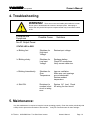
1
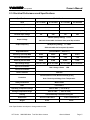
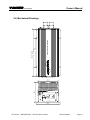
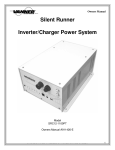
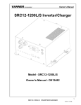
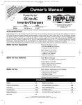
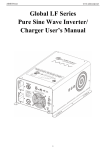
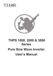
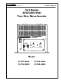
VANNER Incorporated
Owner’s Manual
VLT Series
2000/3000 Watt
True Sine Wave Inverter
PURE SINE WAVE
INVERTER
ON
I
OFF
0
REMO.
INPUT
LEVEL
LOAD
LEVEL
STATUS
FREQ.
PWR.
SAV.
S4
S3
S2
S1
O
I
AC OUTPUT
Models
VLT12-2000
VLT12-3000
VLT Series
2000/3000 Watt True Sine Wave Inverter
VLT24-2000
VLT24-3000
Owner's Manual
Page 1
VANNER Incorporated
Owner’s Manual
Table of Contents
1.
2.
3.
Important Safety Information…………….…………….
3
1-1
General Safety Precautions…………………
3
1-2
Battery Precautions……………………..……..
3
Features and Specifications…………..………………..
4
2-1
Standard Features……………………….…….
4
2-2
Typical AC Loads……………………….…..….
4
2-3
Electrical Performance and Specifications …
5
2-4
Mechanical Drawings………………….……….
6
Installation and Operation………….…………….………
7
3-1
Front Panel Area………….…….……………...
7~9
3-2
Rear Panel Area……..………………….………
10~11
3-3
Protection Features and Setpoints………....…
11
3-4
Installation location..……………………….……
12
3-5
DC Wire, Fuse Sizes and Connections .….….
13~14
3-6
AC Neutral Bonding, Replacement GFCI's
14~15
3-7
Inverter Operation…………………………..…
15
4.
Troubleshooting Guide………………….……………..…
16
5.
Maintenance……………….…………………………….…
16
VLT Series
2000/3000 Watt True Sine Wave Inverter
Owner's Manual
Page 2
VANNER Incorporated
Owner’s Manual
1. Important Safety Information
1
WARNING!
Before using the Inverter, please read
and save the safety instructions.
1-1. General Safety Precautions
•
•
•
Do not expose the inverter to water, mist, snow, spray, or dust.
To reduce risk of hazard, do not cover or obstruct the ventilation openings.
Do not install the inverter in a zero-clearance compartment. Overheating may occur.
•
•
To avoid risk of fire and electronic shock, be sure all DC and AC wiring is in good condition and not undersized.
Do not operate the inverter with damaged or substandard wiring.
•
•
This inverter contains components that can cause arcs and sparks.
To prevent fire or explosion do not locate flammable materials near the inverter.
1-2. Precautions When Working with Batteries
•
•
•
•
If battery acid contacts skin or clothing, wash it off with soap and water immediately. If battery acid contacts
your eyes, wash it out with cold running water for at least 20 minutes and get medical attention immediately.
Never smoke or create sparks or flame in the vicinity of the battery or the engine.
Do not drop a metal tool on the battery. The resulting spark or short circuit may cause the battery to explode.
Remove jewelry and personal metal items such as rings, bracelets, necklaces, and watches when working with
batteries. Jewelry may cause a short circuit creating very high temperatures which can melt metal items and
cause severe burns.
VLT Series
2000/3000 Watt True Sine Wave Inverter
Owner's Manual
Page 3
VANNER Incorporated
Owner’s Manual
2. Features and Specifications
2-1. Standard Features
•
Pure sine wave output (THD < 3%)
•
Output frequency 60Hz (50Hz selectable by dip switch)
•
Input & output fully isolated design
•
Power Saving Mode to conserve energy
•
High efficiency 89~94%
•
Able to drive highly reactive & capacitive loads
•
Tri-Color indicators show input voltage & output load level
•
Temperature controlled cooling fan
•
Advanced microprocessor
•
Protection
Input low voltage
Input over voltage
Low battery alarm
Overload
Short circuit
Over temperature
2-2. Typical AC Loads
2-2-1. Power tools – circular saws, drills, grinders, sanders, buffers, weed and hedge trimmers, air
compressors, etc.
2-2-2. Office equipment – computers, printers, monitors, facsimile machines, scanner, etc.
2-2-3. Household appliances – vacuum cleaners, fans, fluorescent and incandescent lights, shavers, sewing
machines.
2-2-4. Kitchen appliances – coffee makers, blenders, ice markers, toasters, etc.
2-2-5. Industrial equipment – metal halide lamp, high – pressure sodium lamp, etc.
2-2-6. Home entertainment electronics – television, VCRs, video games, stereos, musical instruments,
satellite equipment, etc.
VLT Series
2000/3000 Watt True Sine Wave Inverter
Owner's Manual
Page 4
VANNER Incorporated
Owner’s Manual
2-3. Electrical Performance and Specifications
Specifications
Item
Model Number
VLT12-2000
VLT24-2000
VLT12-3000
VLT24-3000
Continuous Output Power
2000W
3000W
Maximum Output Power (3Min.)
2300W
3300W
Surge Rating
4000W
6000W
Nominal Input voltage
12V
24V
12V
120VAC (factory setting)
Output Voltage
24V
+/- 5%
100/110/115 selectable via internal front panel dip switches
Output Frequency
60Hz (factory setting)
+/- 0.05%
50Hz selectable via front panel dip switch
Output Waveform
True Sine Wave ( THD < 3% )
Efficiency (full load) MAX
89.0%
92.0%
88.0%
91.0%
No Load Current Draw
2.8A
1.5A
3.0A
1.6A
Stand-By Current Draw
0.60A
0.30A
0.55A
0.35A
Input Voltage Range
10.5-15.0 VDC
21.0-30.0 VDC
10.5-15.0 VDC
21.0-30.0 VDC
Input Level Indicator
Red / Orange / Green
LED
Load Level Indicator
Failure Indicator
Red LED
Overload, Short Circuit, Reverse Polarity (Fuse),
Protection
Over / Under Input Voltage, Over Temperature.
Safety Certification
Meets UL458
EMC
FCC Class A
Operating Temperature Range
32°F to 104°F ( 0°C to 40°C)
Storage Temperature Range
Cooling
-22°F to 160°F
( -30°C to 70°C)
Thermostatically controlled cooling fan
Dimensions
16.6 L x 8.2 W x 6.5 H
17.8 L x 8.2 W x 6.5 H
Weight
20 lbs
22 lbs
Note: Specifications are subject to change without notice.
VLT Series
2000/3000 Watt True Sine Wave Inverter
Owner's Manual
Page 5
VANNER Incorporated
Owner’s Manual
PURE SINE WAVE INVERTER
2-4. Mechanical Drawings
9.65
(245mm)
VLT-2000
14.49
(368MM)
VLT-3000
15.67
(398mm)
6.97
(177mm)
PURE SINE WAVE
INVERTER
6.51
(166mm)
ON
I
OFF
0
REMO.
INPUT
LEVEL
LOAD
LEVEL
STATUS
FREQ.
PWR.
SAV.
S4
S3
S2
S1
O
I
AC OUTPUT
8.23
(209mm)
VLT Series
2000/3000 Watt True Sine Wave Inverter
Owner's Manual
Page 6
VANNER Incorporated
Owner’s Manual
3. Installation and Operation
This inverter is one of the most advanced line of mobile AC power systems. For best performance the inverter must
be installed and used properly. Please read this instruction manual before installing and operating the inverter.
3-1. Front Panel Area:
3-1-1. Front view:
PURE SINE WAVE
INVERTER
ON
I
OFF
0
REMO.
INPUT
LEVEL
LOAD
LEVEL
STATUS
FREQ.
PWR.
SAV.
S4
S3
S2
S1
O
I
AC OUTPUT
3-1-2. ON / OFF/ REMOTE (Main) Rocker Switch:
Before installing the inverter, be sure the main rocker switch is set to “OFF”.
3-1-2-1. AC Output Wiring Methods: Three AC output wiring methods are provided.
•
•
•
GFCI Protected Receptacle
GFCI Protected Hardwired Output ( LOAD terminals on GFCI Receptacle )
Non-GFCI Hardwired output via terminal strip inside receptacle compartment.
VLT Series
2000/3000 Watt True Sine Wave Inverter
Owner's Manual
Page 7
VANNER Incorporated
Owner’s Manual
3-1-3. DC Input Voltage Display
LED Status
DC 12V
DC 24V
RED Slow Blink
10.3~10.6
20.5~21.2
RED
10.6~11.0
21.2~21.8
ORANGE
11.0~12.1
21.8~24.1
GREEN
12.1~14.2
24.1~28.6
ORANGE Blink
14.2~15.0
28.6~30.0
OVER RED Blink
Above 15.0
Above 30.0
3-1-4. AC Load Display (Watts)
Unit
Power
DARK
GREEN
2000W
0 ~ 160W
160 ~ 660W
660 ~ 1500W 1500 ~ 1920W Over 2000W
3000W
0 ~ 240W
240 ~ 990W
990 ~ 2250W 2250 ~ 2880W Over 3000W
ORANGE
RED
RED BLINK
3-1-5. Status:Display Power & Fault Status
Green LED
LED Signal
Solid
Power OK
Slow Blink
Power Saving
Red LED
LED Signal
Status
Fast Blink
Overvoltage Shutdown
Slow Blink
Undervoltage Shutdown
Intermittent Blink
33
33
Solid
VLT Series
Status
2000/3000 Watt True Sine Wave Inverter
33
Overtemp Shutdown
Overload Shutdown
Owner's Manual
Page 8
VANNER Incorporated
Owner’s Manual
3-1-6. AC Frequency Selection: AC output frequency is selected by Dip Switch “S4”.
Important Note: 60Hz AC loads may be damaged if 50Hz is selected.
The unit must be turned OFF/ON to accept new dip switch settings.
Frequency
S4
50 HZ
OFF (left)
60 HZ
ON (right)
3-1-6-1. AC Voltage Selection: Only qualified persons should change the AC output voltage setting. The AC
output voltage is selected by a two-position dip switch located inside the inverter behind the ON/OFF/Remote
switch. To access the internal 2-position dip switch, remove the top cover by removing the front four and rear four
screws.
The unit must be turned OFF/ON to accept new dip switch settings.
Display Panel internal 2-position DIP Switch Setting
AC Output Voltage
Switch 1
Switch 2
120 VAC
ON (up)
ON (up)
115 VAC
ON (up)
OFF (down)
110 VAC
OFF (down)
ON (up)
100 VAC
OFF (down)
OFF (down)
3-1-7. Load Demand (Power Saving Mode): The Load Demand feature allows the inverter to "go to
sleep" if the inverter is ON but no AC loads are present. Load Demand is adjustable via Dip Switches S1, S2 and
S3 on the front panel. .
Example: With the Load Demand Threshold watt setting at 45W, a load greater than 45W is required to "keep the
inverter awake" to produce AC power. If the AC load falls below 45W the inverter will "go to sleep", entering Load
Demand power saving mode.
The unit must be turned OFF/ON to accept new dip switch settings.
Load Demand
S1
S2
Threshold Watts
S3
Load Demand OFF
OFF
OFF
OFF
45W
ON
OFF
OFF
85W
OFF
ON
OFF
130W
ON
ON
OFF
175W
OFF
OFF
ON
220W
ON
OFF
ON
265W
OFF
ON
ON
300W
ON
ON
ON
VLT Series
2000/3000 Watt True Sine Wave Inverter
Owner's Manual
Page 9
VANNER Incorporated
Owner’s Manual
3-2. Rear Panel Area:
DC INPUT
POS(+)
REMOTE
PORT
NEG(-)
WARNING:
ENB
ENB
GND
REVERSE
POLARITY
WILL DAMAGE
UNIT.
CHASSIS
GROUND
3-2-1. Remote Port: The modular jack labeled Remote Port is not used.
3-2-2. Remote Control Connector: (The Remote Control Connector is enabled when the ON/OFF/Remote
main rocker switch, located on the front of the inverter, is in the Remote position.) This three-position connector,
Phoenix part number 1911868, is labeled GND, ENBBAR, and ENB. Use this connector with a customer supplied
SPST switch to provide remote ON/OFF control of the inverter. Remote switch circuit arrangement options are +12v
to ENB, or Battery Negative to ENBBAR, or GND to ENBBAR. The most common application (+12v to ENB) uses a
+12v hot-in-run from vehicle fuse panel to turn inverter ON when vehicle is ON, and OFF when vehicle is OFF.
3-2-2. Cooling Fans and Ventilation:
Maintain at least 1" clearance all around the inverter at all times.
VLT Series
2000/3000 Watt True Sine Wave Inverter
Owner's Manual
Page 10
VANNER Incorporated
Owner’s Manual
3-2-3. DC Input Terminals:
Connect DC cables, battery positive (+) to inverter positive (red); battery negative (-) to inverter negative (black).
Be aware, there will be a large spark when the last DC connection is made. Be very careful to NEVER connect DC
terminals to the inverter backwards (inverter positive to battery negative). Reverse polarity connection may cause
permanent damage to the inverter.
DC Input Voltage
Model
Minimum
Maximum
12 V
10.5
15.0
24 V
21.0
30.0
3-2-4. Chassis Ground Lug:
Use a # 8 AWG or larger wire to connect inverter chassis ground lug to vehicle chassis.
WARNING!
Operating the inverter without a proper ground
connection may cause an electrical hazard.
3-3. Protection Features and Setpoints:
DC Input (VDC)
Model
Over Voltage
Under
Voltage
ShutRestart
down
Over Temperature Protection
Under Voltage
Shut-
ShutRestart
Alarm
down
15.3
14.3
11.0
10.2
12.7
24 V
30.6
28.8
22.0
20.3
25.2
2000/3000 Watt True Sine Wave Inverter
HEAT SINK
Shut-
Restart
down
12 V
VLT Series
INTERIOR
70°
Restart
down
45°
90°
Owner's Manual
60°
Page 11
VANNER Incorporated
Owner’s Manual
3-4. Installation location:
Install the inverter in an environment that meets the following requirements:
3-4-1. Dry – Do not allow water to drip on or to get inside the inverter.
3-4-2. Cool – Ambient air temperature should be between 32°F and 105°F, the cooler the better.
3-4-3. Safe – Do not install the inverter in a battery compartment or other areas where flammable fumes may
exist, such as fuel storage areas.
3-4-4. Ventilated –Maintain at least 1" clearance all around inverter.
back are not obstructed.
Be sure ventilation openings on front and
3-4-5. Dust free– Do not install the Inverter in dusty environments. Dust will be drawn inside and will greatly
shorten the life of the inverter.
3-4-6. Close to batteries but not exposed to battery fumes – Use the recommended wire lengths and
sizes (see section 3-5). Avoid excessive cable lengths. Do not install the Inverter in a non-vented compartment with
the batteries. Do not mount the Inverter where it will be exposed to the gases produced by the batteries. Battery
gases are very corrosive. Prolonged exposure will damage the Inverter.
WARNING!
Shock Hazard.
Before proceeding further, verify that the Inverter is NOT
connected to batteries, and that all wiring is
disconnected from any electrical sources.
NEVER connect the inverter AC output terminals to an
incoming AC source.
VLT Series
2000/3000 Watt True Sine Wave Inverter
Owner's Manual
Page 12
VANNER Incorporated
Owner’s Manual
3-5. DC Wire and Fuse Sizes:
Use the following DC cable and inline fuse sizes. DC cables should be as short as possible (ideally less than 10
feet, never exceeding 20') and large enough to handle the required current in accordance with the electrical codes
or regulations applicable to the installation. DC cables that are too small or too long will cause DC voltage drop
which will result in deteriorated inverter performance such as poor surge capability and frequent low-input voltage
warnings and shutdowns.
Model Number
VLT12-2000
VLT24-2000
VLT12-3000
VLT24-3000
Distance from battery to inverter in feet
(Length of cable needed is 2 times the distance.)
Cable Size
1/0
2/0
3/0
4/0
250MCM
10
13
16
21
24
20
26
33
42
49
6
8
11
14
16
13
17
22
28
32
Fuse (Bussmann)
Vanner part number
AMG250
013916
AMG175
013913
AMG300
013917
AMG175
013913
Fuse Holder
Vanner part number 012992 (Bussmann FMG Series)
3-5-1. DC Connections:
When ready to connect DC cables, connect battery positive (+) to inverter positive; connect battery negative (-) to
inverter negative. Be aware, there will be a large spark when the last DC connection is made. This is normal.
Never connect inverter positive to battery negative. Be very careful to NEVER connect DC terminals
to the inverter backwards. Reverse polarity connection may cause permanent damage to the inverter.
Torque the DC terminal bolts to 9 -12 ft-lbs.
WARNING!
Loose DC connections will overheat and could cause
a fire.
WARNING!
To protect the DC cables, and to protect the inverter if
positive and negative are reversed, a DC fuse must be
installed in the positive inverter cable within 18" of the
battery. Failure to place a fuse in the inverter positive
cable will void warranty.
VLT Series
2000/3000 Watt True Sine Wave Inverter
Owner's Manual
Page 13
VANNER Incorporated
Owner’s Manual
Battery to inverter cable connection
DC INPUT
POS(+)
NEG(-)
WARNING:
REMOTE
PORT
REVERSE POLARITY
WILL DAMAGE UNIT
SHOCK HAZARD.
DO NOT OPEN. NO
USER SERVICEABLE
PARTS INSIDE.
CHASSIS
GROUND
INLINE FUSE
SPRING WASHER
PVC WIRE
Do not place anything between
battery cable lug and terminal surface.
Assemble exactly as shown.
VLT Series
2000/3000 Watt True Sine Wave Inverter
Owner's Manual
Page 14
VANNER Incorporated
Owner’s Manual
3-6. AC Neutral Bonding and GFCI's:
3-6-1. AC Neutral Bonding
The neutral conductor of the inverter AC output circuit is connected to ground (the bare wire) inside the inverter.
This conforms to National Electrical Code requirements that separately derived AC sources (such as inverters and
generators) must have their neutral conductors tied to ground. The AC output ground wire should go to the
grounding point for the AC loads; for example, if there is a distribution panel ground bus. Do not connect neutral to
ground in any panel, receptacle or device downstream of a GFCI as this would cause the GFCI to trip.
3-6-2.
GFCI Receptacles
While the pure sine wave output of the Inverter is equivalent to the waveform provided by utilities, it is possible that
some GFCI's may not perform properly on inverter power. If additional GFCI receptacles are needed use Hubbell
GFR5252WA or Pass & Seymour 2091 or 2094.
3-7. Inverter Operation:
Use the ON/OFF/REMOTE main rocker switch on the front panel to turn the inverter ON.
3-7-1. Set the rocker switch to the ON position to turn the inverter ON. Notice the beeps and the activity of the
indicator light display. The Status led should be green indicating the inverter is ready to deliver AC power to the
loads. If multiple AC loads will be operated at the same time it may be necessary to turn the loads ON one-at-atime to prevent inverter overload due to the initial surge required to start the loads.
3-7-2. Set the rocker switch to the OFF position to turn the inverter OFF.
3-7-3. Set the rocker switch to the REMOTE position if a customer-supplied remote control switch is used with the
Remote Control Connector, located on the inverter back panel. (See section 3-2-2.)
VLT Series
2000/3000 Watt True Sine Wave Inverter
Owner's Manual
Page 15
VANNER Incorporated
Owner’s Manual
4. Troubleshooting
WARNING!
There are no user serviceable parts inside the inverter.
Do not open or disassemble the inverter to attempt repairs. Attempting to
service the unit yourself will expose components that may cause electric shock
or fire.
Problems and
Symptoms
Possible Cause
Solutions
No AC Output Power
STATUS LED is RED
a. Blinking fast
Shutdown for
High Input
Voltage.
Reduce input voltage.
b. Blinking slowly.
Shutdown for
Low Input
Voltage.
Recharge battery.
Check DC connections.
Verify correct cable size.
c. Blinking Intermittently.
Shutdown for
Over
Temperature.
Improve ventilation.
Make sure vent openings
are not obstructed.
Reduce ambient
temperature.
d. Solid ON.
Shutdown for
overload, short
circuit or wiring
error.
Reduce AC load. Check
AC wiring for short circuit.
5. Maintenance:
Very little maintenance is required to keep the inverter operating properly. Clean the exterior periodically with
a damp cloth to prevent accumulation of dust and dirt. Verify DC connections are all clean and tight.
VLT Series
2000/3000 Watt True Sine Wave Inverter
Owner's Manual
Page 16
VANNER Incorporated
VLT Series
2000/3000 Watt True Sine Wave Inverter
Owner’s Manual
Owner's Manual
Page 17
VANNER Incorporated
Owner’s Manual
Vanner Inc
4282 Reynolds Drive
Hilliard, OH 43026
800-227-6937
800-ACPOWER
email: [email protected]
www.vanner.com
D914572-A June 3, 2008
VLT Series
2000/3000 Watt True Sine Wave Inverter
Owner's Manual
Page 18