1
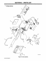
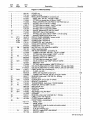
OM-182 702A
June 1997
Eff. w/Serial Number KH387456
Miller
Processes
Cutting
Gouging
Air Plasma
The Power fBlue.
and
Description
Air Plasma Cutter
FILE COPY
~ETUR~3 TO ~
Spectrumfi 300 (50/60 Hz)
j~
Visit
our
website. at
www~MiIloiWCldS~com
OWNERS
MANUAL
From Miller to You
Thank you and
you
can
get the
have time to do it any other way.
you dont
Thats
congratulations on choosing Miller. Now
job done and get it done right. We know
why
when Niels Miller first started
building arc
products offered
long-lasting value and superior quality. Like you, his
customers couldnt afford anything less. Miller products
had to be more than the best they could be. They had to
be the best you could buy.
welders in 1929, he made
sure
his
people that build and sell Miller products continue the
Theyre just as committed to providing equipment and service
meets the high standards of quality and value established in 1929.
Today,
the
tradition.
that
This Owners
Miller
help
Manual is
products.
designed
to
help
you get the most out of your
Please take time to read the
yourself against potential
you protect
Safety precautions. They
hazards
made installation and
on
will
the worksite. Weve
and easy.
of
reliable
years
service with proper maintenance. And if for
some reason the unit needs repair, theres
a
4k1IiIIW
With Miller you
I REGISTERED
SYSTEM
_______________
can
operation quick
count
on
Troubleshooting section that will help you
figure out what the problem is. The parts list
will then help you to decide which exact part
you may need to fix the problem. Warranty and
service information for your particular model
are also provided.
Miller Is tIe first welding equip
menttunutacturorlntbeU.S.A.te
Is registered to Ike ISO 9001
Quality System Standard.
~1~Th1~ 1~ftflfl~~
L~
Working as lard as yen I,. every
.me
Miller Electric manufactures
of welders and
welding
For information
products,
on
catalog
~
equipment.
quality Miller
~
~,
local Miller distributor
to receive the latest full line
individual
full line
related
other
contact your
a
power source trim Miller is
lacked ly the most lasslo-troe
warranty I. the buslooss.
catalog
or
sheets. To locate your nearest
distributor call 1-800-4-A-Miller.
f/IA Miller
heThwer9fBhse~
Call
1 -800-4-A-MILLER
for your local
Miller dlslributor.
TABLE OF CONTENTS
SECTION 1
Service
You always get the fast,
reliable response you
need. Most replacement
parts can be in your
answers
SECTION 1
1-1.
1-2.
1-3.
to the
Contact your distributor.
expertise
of the
distributor and Miller is
there to
help you, every
step of the way.
a
more
parts
Technical
provides
detailed service and
information for your
SECURITE
-
normes
1-5.
Information
sur
SECTION 2
2-1.
2-2.
2-3.
2-4.
2-7.
-
los
7
7
champs ØlectromagnØtiques
INSTALLATION
Selecting A Location
Connecting Work Clamp
Connecting Input Power
9
9
9
10
11
And Gas/Air
Supply
website at
www.MIIIeiWeId&com
12
12
13
Controls
13
SECTION 6- PARTS LIST
our
8
9
Specifications
Symbols And Definitions
Cutting Speed
Duty Cycle And Overheating
practical information on
welding, process applica
tions, and Miller products,
For
visit
5
le fonctionnement
de sØcurit~
SECTION 4- MAINTENANCE & TROUBLESHOOTING
a
5
5
SECTION 3-OPERATION
3-1.
2
3
LIRE AVANT UTILISATION
Technical
Manual, contact your local
distributor. Your distributor
can also supply you with
Welding Process Manuals
such as SMAW, GTAW,
GMAW, and GMAW-P.
unit. To obtain
And Maintenance
Signification des symboles
Dangers lies au coupage a Iarc au plasma
Dangers supplØmentaires en relation avec Iinstallation,
Principales
2-6.
Manual which
1
4
CONSIGNES DE
1-4.
2-5.
Miller offers
-
1
1
et Ia maintenance
tough welding questions?
The
READ BEFORE USING
EMF Information
hands in 24 hours.
Support
Need fast
-
1-5.
1-3.
gives
you
SAFETY PRECAUTIONS
1-4.
1-2.
Your distributor
-
Symbol Usage
Plasma Arc Cutting Hazards
Additional Symbols For Installation, Operation,
Principal Safety Standards
1-1.
14
4-1.
Routine Maintenance
4-2.
Overload Protection: Trouble
4-3.
Torch And Work Cable Connections
16
4-4.
Troubleshooting
17
14
Lights & Checking Shield Cup Shutdown System
15
SECTION 5- ELECTRICAL DIAGRAM
WARRANTY
.20
SECTION 1
SAFETY PRECAUTIONS
-
READ BEFORE USING
-
porn
1-1
Symbol Usage
Means Warning! Watch Out! There are possible
hazards with this procedure! The possible hazards are
a
A
_nd_5/97
shown in the
Marks
special safety
a
~ Means Note;
1-2
adjoining symbols.
not
message.
This group of symbols means Warning! Watch Out! possible
ELECTRIC SHOCK, MOVING PARTS, and HOT PARTS hazards.
Consult symbols and related instructions below for necessary
actions to avoid the hazards.
safety related.
Cutting
Plasma Arc
Hazards
~
A The symbols
are used throughout this manual
identify possible hazards. When you
shown below
to call attention to and
the symbol, watch out, and follow the related instructions
to avoid the hazard. The safety Information given below is
only a summary of the more complete safety information
~
Do not touch live electrical
parts.
dry, hole-free insulating gloves
Wear
and
body protection.
see
found in the Safety Standards listed in Section 1-4. Read and
follow all Safety Standards.
A
Only qualified persons should install, operate, maintain, and
repair this unit.
A
During operation, keep everybody, especially children, away.
i
w
iriG
can cause
fire
or
explosion
flying sparks
possible, tightly
Be alert that
sparks
Watch br fire, and
Be
aware
cause
that
fire
strike flammable material.
keep
cutting
a
on a
openings
on
closed containers such
prevent cutting
to
unknown
to
If
cutting can easily go
adjacent areas.
fire extinguisher nearby.
ceiling, floor, bulkhead, or partition
Connect work cable to the work
practical
(10.7 m) of the cutting arc.
them with approved covers.
can
the hidden side.
on
Do not cut
paths
and
as
as
current from
causing
tanks
parts
at
once.
a
safety
Keep
all
electric shock and fire hazards.
atmospheres containing explosive
pressurized cylinders, pipes,
or
or
vapors.
vessels.
Do not cut containers that have held combustibles.
Wear oil-free
protective garments such as leather gloves, heavy
shirt, cuffless trousers, high shoes, and a cap.
Do not locate unit
on or over
~ki~,
con
Do not
Use
harness if
panels
bypass
and
or
try
working above floor level.
covers
securely in place.
safety interlock systems.
to defeat the
only torch(es) specified
in Owners
Manual.
Keep away from torch tip and pilot arc when trigger is pressed.
Clamp work cable with good metal-to-metal contact to workpiece
(not piece that will fall away) or worktable as near the cut as
practical.
Insulate work
clamp
when not connected to
contact with any metal
workpiece
to
prevent
object.
combustible surfaces.
Remove any combustibles, such as a butane
from your person before doing any cutting.
7
grounding
Ground the workpiece to a good electrical (earth) ground if re
quired by codes.
Use only well-maintained equipment. Repair or replace damaged
Wear
dust
attach proper
Frequently inspect input power cord for damage or bare wiring
replace cord immediately if damaged bare wiring can kill.
Turn off all equipment when not in use.
Inspect and replace any worn or damaged torch cable leads.
Do not wrap torch cable around your body.
drums.
Never cut containers with potentially flammable materials inside
must be emptied and properly cleaned first.
Do not cut
making input connections,
cutting area as
traveling long, possibly
or
close to the
they
Do not cut in
Manual and national, state, and local codes.
sure that input power cord ground wire is properly
ground terminal in disconnect box or that cord plug is
connected to a properly grounded receptacle outlet
always
verify the supply ground.
and hot materials from
small cracks and
through
cover
ground.
ductor first.
Remove all flammables within 35 ft
this is not
or
connected to
flying sparks and hot metal.
can
parts if in contact with the work
checking, cleaning, or changing torch parts.
Disconnect input power before installing or servicing this equip
ment. Lockout/tagout input power according to OSHA CFR
191 0.147 (see Safety Standards).
Properly install and ground this equipment according to its Own
When
and others from
Do not cut where
Do not touch torch
Turn off power before
Check and be
cutting.
yourself
yourself from work and ground using dry insulating mats
or covers big enough to prevent any physical contact with the work
or ground.
ers
Hot metal and sparks blow out from the cutting arc.
The flying sparks and hot metal, hot workpiece, and
hot equipment can cause fires and bums. Check
and be sure the area is safe before doing any
Protect
Insulate
lighter
or
matches,
SIGNIFICANT DC VOLTAGE exists after removal of
input power on inverters.
Turn OFF
ELECTRIC SHOCK can~ kill
I
Touching
I
shocks
inverter, disconnect input power, and discharge input
capacitors according to instructions in Maintenance Section
before touching any parts.
live
electrical parts can cause fatal
burns. The torch and work circuit
are electrically live whenever the output is on. The
_J input power circuit and machine internal circuits are
also live when power is on. Plasma arc cutting
requires higher voltages than welding to start and maintain the arc
(200 to 400 volts dc are common), but also uses torches designed
with safety interlock systems which turn off the machine when the
shield cup is loosened or if tip touches electrode inside the nozzle.
Incorrectly installed or improperly grounded equipment is a hazard.
or severe
OM-1 82702
Page
1
~..
.
YING SPARKS
can cause
Sparks and hot metal blow out from the cutting
Chipping and grinding cause flying metal.
Wear
approved face shield
Wear proper
body protection
Wearflame-resistant
entering
or
ear
safety goggles with side
to
only if it is well ventilated, or while
air-supplied respirator. Fumes from cutting and
oxygen depletion can alter air quality causing injury or death. Be
sure the breathing air is safe.
Do not cut in locations near degreasing, cleaning, or spraying op
injury
arc.
protect skin.
an
Do not cut
bum eyes and skin
coated metals, such as galvanized, lead, or
unless the coating is removed from the
on
Do not cut containers with toxic
protection (helmet or shield)
emptied
and
with correct shade of filter
properly
reactive materials inside
I
or
must be
cleaned first.
PLASMA ARC
protect your face and eyes when cutting or watching. ANSI
Z49.1 (see Safety Standards) suggests a No. 9 shade (with No. 8
can cause
injury
~
The heat from the plasma arc can cause serious
burns. The force of the arc adds greatly to the burn
hazard. The intensely hot and powerful arc can
quickly cut through gloves and tissue.
minimum) for all cutting currents less than 300 amperes. Z49. 1
adds that lighter filter shades may be used when the arc is hidden
by the workpiece. As this is normally the case with low current
cutting, the shades suggested in Table 1 are provided for the oper
as
S
convenience.
Wearapproved safety glasses with side shields under your helmet
or
or
containers that have held toxic or reactive materials they
to
ators
react with vapors to form
cutting area, the area is well ventilated, and if necessary, while
wearing an air-supplied respirator. The coatings and any metals
containing these elements can give off toxic fumes when cut.
Arc rays from the cutting process produce intense
visible and invisible (ultraviolet and infrared) rays
that can burn eyes and skin.
Wear face
arc can
plated steel,
cadmium
ears.
can
a
wearing
erations. The heat and rays of the
highly toxic and irritating gases.
shields.
plugs or ear muffs to prevent sparks from
ARC RAYS
confined space
Work in
Keep away from the torch tip.
Do not grip material near the cutting path.
The
shield.
keep away from torch tip when trig
pilot arc can cause burns
pressed.
ger is
Use protective screens or barriers to protect others from flash and
glare; warn others not to watch the arc.
Wear protective clothing made from durable, flame-resistant
material (leather and wool) and foot protection.
Table 1.
Eye Protection
Current Level In
4060
80
exposed body
all
Point torch away from your
body and toward work when pressing
immediately.
Turn off power source and disconnect input power before disas
sembling torch or changing torch parts.
Use only torch(es) specified in the Owners Manual.
the torch
Cutting
trigger
#4
TkH~
2040
clothing covering
areas.
pilot
arc comes on
Minimum Shade Number
Amperes
Below 20
60
For Plasma Arc
Wear proper flame-retardant
~UNDERS
can
explode
if
damaged
#5
cylinders contain gas under high pressure. If
damaged, a cylinder can explode. Since gas cylin
ders are normally part of metalworking processes,
be sure to treat them carefully.
Gas
#6
#8
_________
_________
compressed gas cylinders from excessive heat, mechani
slag, open flame, sparks, and arcs.
Install and secure cylinders in an upright position by chaining them
to a stationary supportor equipmentcylinder rack to prevent falling
or tipping.
Protect
~7
I
NOISE
can
damage hearing~
cal shocks,
Prolonged noise from some cutting applications
damage hearing if levels exceed limits speci
fled by OSHA (see Safety Standards).
can
Keep cylinders away from any cutting
_________
approved ear plugs or ear muffs if noise
Warn others nearby about noise hazard.
Use
level is
high.
Never cut
ha~a~dous~
arc
torch and
a
on a
pressurized cylinder
explosion
will result.
parts in good condition.
Turn face away from valve outlet when
Keep protective cap
use or
in
connected for
opening cylinder valve.
place over valve except when cylinder is in
use.
Read and follow instructions on compressed gas cylinders, asso
ciated equipment, and CGA publication P-i listed in Safety
fumes and gases.
Standards.
approved air-supplied respirator.
Safety Data Sheets (MSDS5) and the manufac
for metals to be cut, coatings, and cleaners.
If ventilation is poor,
instruction
plasma
only correct gas cylinders, regulators, hoses, and fittings de
signed for the specific application; maintain them and associated
Keep your head out of the fumes. Do not breathe the fumes.
If inside, ventilate the area and/or use exhaust at the arc to remove
Read the Material
other electrical circuits.
Use
Cutting produces fumes and gases. Breathing
these fumes and gases can be hazardous to
your health.
turers
a
cylinder.
~
cuthng
or
Never allow electrical contact between
use an
4~dditIonaI.SymboIsFor I
....
.
.~
HOT PARTS
can cause severe
Do not touch hot
Allow
OM-182 7C12
Page
2
burns.
parts bare handed.
cooling period
before
working
on
torch.
MO VING PARTS
Keep
Keep
away from
can cause
moving parts
injury
such
as
all doors, panels, covers, and
closed and securely in place.
~
fans.
guards
7
FLYING METAL
Wear
can
safety glasses
STATIC(ESD)can damage PC
Injure eyes
with side shields
or
Put
face
shield.
boards
MAGNETIC FIELDS
can
affect
strap
BEFORE
parts.
or
static-proof bags and
or ship PC boards.
Use proper
store, move,
1
wrist
grounded
on
handling
board~]
boxes to
pacemakers
H F RADIATION can cause Interference
Pacemaker
wearers
keep away.
Wearers should consult their doctor before go
ing
near
plasma
arc
High frequency (H.F.) can interfere with radio
navigation, safety services, computers, and
communications equipment.
cutting operations.
Have
OVERUSE can
cause
tronic
OVERHEATING
The
cooling period; follow rated duty cycle.
Reduce amperage (thickness) or reduce duty
cycle before starting to cut again.
Allow
user
is
responsible for having a qualified electrician promptly
problem resulting from the installation.
correct any interference
If notified
by
the FCC about interference,
~..
minimize the
When cutting aluminum underwaterorwith the
watertouching the underside of the aluminum,
free hydrogen gas may collect under the work-
possibility
AD!
piece.
cutting engineer and
regularly
checked and maintained.
Keep high-frequency source doors and panels tightly shut, keep
spark gaps at correct setting, and use grounding and shielding to
of interference.
CUTflNGanca~SØ;Intert~e.
energy can interfere with
electronic equipment such as
Electromagnetic
__________
See your
stop using the equip
ment at once.
Have the installation
EXPL~O DING HYDROGEN h~ard~:~:
only qualified persons familiar with elec
equipment perform this installation.
water table instructions for
help.
sensitive
computers and computer-driven equipment
~1
~
FALLING UNIT
can cause
such
Injury
lifting eye to lift unit only, NOT running
gear, gas cylinders, or any other accessories.
Use equipment of adequate capacity to lift
Use
.
Locate cutting operation
equipment.
are
long enough
to
robots.
100 meters from any sensitive electronic
grounded
If interference still occurs, the user must take extra
as moving the machine, using shielded cables,
measures
sure
this
according
cutting power
source
to this manual.
such
filters,
FIRE OR EXPLOSION hazard
Do not locate unit on, over,
or near
as
is installed and
Be
using lift forks to move unit, be sure forks
extend beyond opposite side of unit.
If
as
To reduce possible interference, keep cables as short
possible, close together, and down low, such as on the floor.
or
shielding
the work
using line
area.
combus
tible surfaces.
Do not install unit
near
flammables.
building wiring be sure power supply system is
rated, and protected to handle this unit.
Do not overload
properly sized,
1~
Piincipal Safety Standards
Safety in Welding and Cutting, ANSI Standard Z49. 1, from American
Welding Society, 550 N.W. LeJeune Rd, Miami FL 33126
Safetyand Health Standards, OSHA 29 CFR 1910, from Superinten
dent of Documents, U.S. Government Printing Office, Washington,
D.C. 20402.
Recommended Practices for Plasma Arc Cutting, American Welding
from American Welding Society, 550
N.W. LeJeune Rd, Miami, FL 33126
Society Standard AWS C5.2,
Safe
Handling of Compressed Gases
in
Cylinders, CGA Pamphlet
P-i, from Compressed Gas Association, 1235 Jefferson Davis High
way, Suite 501, Arlington, VA 22202.
Code forSafelyin Welding and Cutting, CSA Standard W117.2, from
Canadian Standards Association, Standards Sales, 178 Rexdale Bou
levard, Rexdale, Ontario, Canada M9W 1 R3.
Safe Practices For Occupation And Educational Eye And Face Protec
tion, ANSI Standard Z87.1, from American National Standards
Institute, 1430 Broadway, New York, NY 10018.
Recommended Safe Practices for the Preparation for Welding and
Cutting of Containers That Have Held Hazardous Substances, Ameri
can Welding Society Standard AWS F4.1, from American Welding
Society, 550 N.W. LeJeune Rd, Miami, FL 33126
Cutting And Welding Processes, NFPA Standard 51 B, from National
Fire Protection Association, Batterymarch Park, Quincy, MA 02269.
National Electrical Code, NFPA Standard 70, from National Fire Pro
Batterymarch Park, Quincy, MA 02269.
tection Association,
OM-182 702
Page
3
Information
.~:
:~.
Welding Or Cutting And The Effects Of Low
Frequency Electric And Magnetic Fields
Welding or cutting current, as it flows through the welding or cutting
cables, will cause electromagnetic fields. There has been and still is
some concern about such fields. However, after examining more than
500 studies spanning 17 years of research, a special blue ribbon
Considerations About
1.
Keep cables close together by twisting
2.
Arrange
3
Do not coil
4.
committee of the National Research Council concluded that: The
To reduce
magnetic
fields in the
dures:
OM-182 702
Page
4
workplace,
use
the
following
proce-
5.
or
Keep cutting
ator
of evidence, in the committees
body
judgment, has not demonstrated
that exposure to power-frequency electric and magnetic fields is a
human-health hazard. However, studies are still going forth and
evidence continues to be examined. Until the final conclusions of the
research are reached, you may wish to minimize your exposure to
electromagnetic fields when welding or cutting.
cables to
as
one
or
taping
side and away from the
them.
operator.
dra P e cables around Y our bod Y.
power
source
and cables
as
far away from oper
p ractical
Connect work
clamp
to
workpiece
as
close to the cut
as
possi
ble
About Pacemakers:
Pacemaker wearers consult yourdoctorfirst. If cleared byyourdoctor,
then following the above procedures is recommended.
SECTION 1
CONSIGNES DE
-
SECU RITE
-
LIRE AVANT UTILISATION
porn_nd_f re_5/97
Signification dessymboles
1~
Signifie Mise en garde! Soyez vigilant! Cette procedure
prØsente des risques do danger! Ceux-ci sont identifies
par des symboles adjacents aux directives.
a
A
Identifie
Signifie
un
message de sØcuritØ
NOTA
nestpas
particulier.
Ce groupe de symboles signifie Mis~ en garde! Soyez vlgila.nt lily a des ns
ques de danger reijes aux CHOCS ELECTRIQUES, aux PIECES EN MOU
VEMENT et aux PIECES CHAUDES. Reportez-vous aux symboles 01 aux di
rectives ci-dessous at in de connaltre les mesures a prendre pour Øvlter tout
relatif ala sOcuritØ.
danger
DaiigE~ lies: ic.c.Upage ~::1arc
1~.
A
au
.pIa~ma
Les symboles prØsentes cl-aprŁs sont utilisØs tout au long du
present manuel pour attirer votre attention et identifier les
risques de danger. Lorsque vous voyez un symbole, soyez
vigilant et suivez les directives mentionnØes afin dØviter tout
danger,. Les consignes de sØcuritØ prØsentCes cl-aprŁs ne
font que rØsumer llnformation contenue dans les normes de
sØcuritØ ØnumØrØes a Ia section 1-5. Veulllez lire et respecter
toutes ces normes de sØcuritØ.
A
Llnstallatlon,
lutilisation,
doivent Œtre confiØs
A
Au
cours
de
qu
lentretlen et les reparations
des personnes qualifiees.
ne
lutilisatlon, tenirtoute personne a lØcartet plus
particuliŁrement
les enfants.
LE.COUPAGE
teu
ou
presante~uri.iiØque .de~
dtexptosion
chaud et des Øtincelles
au moment du coupage.
Les Łtincelles et le metal chaud, Ia piŁce a couper
chauffOo et lequipement chaud peuvcnt causer un
feu ou des brCilures. Avant de commencer a travailler, assurezvous
que lendroit est sØcuritaire.
Des
particules de metal
peuvent jaillir de Ia piŁce
ProtØgezvous,
ainsi que toute autre personne travaillant
lioux, contre les Øtincelles et le metal chaud.
No coupez pas dans un endroil o
dre des matiŁres inflammables.
sur
les
des Øtincelles pourraient attoin
Deplacez toute matiŁre inflammable se trouvant a lintŁrieur dun
pOrimŁtre de 10,7 m (35 pi) de Ia piŁce a couper. Si cola est im
possible, vous devez los couvrir avec des housses approuvees et
bien ajustØes.
Assurezvous quaucune Øtincelle ni particule do metal ne peut so
glisser dans de petitos fissures ou tomber dans dautres piŁces.
Afin dØliminer tout risque do fou, soyez vigilant et gardez toujours
un extincteur a Ia portŁo do Ia main.
Si vous coupez sur un plafond, un plancher ou une cloison, soyez
conscient que cela pout ontraIner un feu de lautro ctO.
No coupez pas sur un contonant fermØ tel quun rØsorvoir ou un
bidon.
Fixez le cable do masse sur Ia piŁce a coupor, le plus prŁs possible
do Ia zone a couper atm do prØvenir quo le courant do coupage ne
pronne uno trajectoiro inconnuo ou longuo et no causo ainsi uno
dØchargo electrique ou un fou.
Nocoupezjamaisdoscontonantsqui peuvontcontonirdosmatiŁ
ros inflammablos. Vous dovoz on premier lieu los vidor et les
nottoyer convonablement.
No coupez pas dans un ondroit o latmosphŁre risque do contenir
do Ia poussiŁre ou dos vapeurs explosives.
No coupoz pas do boutoilles, do
rises.
tuyaux ou do
contenants prossu
poste
sur uno
surface combustible
UNE DEcHARGE~ELEc TRIO UE pe Ut
entraIriŁrlÆ mart.
Lo fait do toucher a une piŁce Ølectrique sous
tension pout donnor uno decharge fatale ou
ontrainor dos brOlures graves. Lo chalumoau otlo
circuit de masse sont automatiquomont actits
le
Iorsque
poste est sous tension. Lalimentation dentrŁo et los
circuits intornes do Iappareil Ia sont Łgalemont. Le coupage au
plasma darc exige des tensions plus ØlevØos quo le soudage pour
amorcer et maintonir Iarc
(souvent do 200 a 400 V CC), cost
pourquoi on fait appel a des chalumeaux concus avec un systŁme
do vorrouillage securitairo qui met Iapparoil hors tension Iorsque Ia
capsulo antifeu est dessorrŁo ou silo tube toucho Ielectrode a
lintŁrieurde Ia buso. Un posto incorrectement installØ ou inadØqua
tomont mis a Ia terre constitue un danger.
No touchoz pas aux piŁces loctriquos sous tension.
Portoz des gants isolants ot des vØtomonts do protection
sans trous.
ou
Avant le coupage, retirez tout combustible do vos
exemplo un briquet au butane ou des allumettos.
audessus
lsolozvous de Ia piŁce a couper ot du solon utilisant des housses
dos tapis assez grands afin dØvitor tout contact physique avoc
Ia piŁce a couper ou 10 sol.
Ne touchez pas aux piŁces du chalumoau si
Ia piŁce a couper ou le sot.
par
vous
Œtes
en
contact
avec
Mettoz lapparoil hors tension avant deffectuer Ia verification,
nottoyage ou lo changoment dune piŁce du chalumeau.
le
Coupoz lalimentation dentrŁo avant dinstaller Iappareil ou dot
foctuor Ientrotien. Vorrouillez ou etiquetez Ia sortie dalimontation
solon Ia norme OSHA 29 CFR 1910.147 (reportozvous aux Prin
cipalos
normes
do
sØcuritØ).
Installez Ia posto correctement et mettezle ala terre convenablo
mont solon los consignes du manuel do loperateur et les normes
nationales, provincialos et locales.
Assurezvous quo lo fil do terre du cordon dalimontation est cor
roctoment rouØ ala borne do terre dans Ia boito do coupure ou quo
Ia fiche du cordon ost branchØo a une prise correctemont miso ala
terre
vous devez toujours verifier Ia miso a Ia terre.
Avant doffectuor los connexions
le bon fil de terre.
dalimontatiori,
vous
dovez rolior
VØrifiez
rer
frequomment le cordon dalimentation afin de vous assu
nest pas altØrØ ou a nu, remplacozlo immØdiatomont sil
Un fil a nu pout entralner Ia mort.
quil
Iost.
LØquipement
doit Øtre hors tension
VØrifioz ot remplacez los
sont usØos ou altereos.
cosses
Le cable du chalumoau
ne
Iorsquil
nest pas utilisØ.
du cable du chalumoau si olles
doit pas senrouler
autour do votre
corps.
Si los normes 10
stipulent, Ia piŁce a coupor doit Łtre miso ala terre.
uniquementde lequipemont en bonno condition. RØparoz
romplacez immØdiatement touto piŁce altØrØo.
Utilisoz
Portoz
du sol.
un
harnais do sØcuritØ si
Assurozvous
mont
place.
Nessayez pas
vous
devez travailler audessus
quo tousles panneaux 01 couvorcles sont
corrode
on
de sØcuritØ
pochos,
secs et
ou
ou
No coupez pas de contenants qui ont deja rou dos combustibles.
Portoz des vŒtemonts do protection exempts dhuilo lois quo dos
gants en cuir, uno vosto rØsistanto, dos pantalons sans rovors,
des boltos ot un casquo.
No placoz pas le
de celleci.
.
ou
dallor ~ lencontro
do los contourner.
(Jtilisez uniquement le
manuel de lopOrateur.
ou
dos
systŁmos
do
vorrrouillago
los chalumeaux recommandØs dans le
OM-182 702
Page
5
Napprochez
pas le tube du chalumeau et arc
photo lorsque Ia gchette
est enfoncØo.
Le cable do
doit Œtre pince corroctement sur Ia piŁce a couper, mOtal
(et non de telle sorte quiI puisso so detacher), ou sur Ia table
plus pres possible de Ia ligne de coupago.
Isoler Ia pince de masse quand pas mis a Ia piŁce pour Øviter le contact
avec tout objet mØtallique.
masse
Contre metal
de travail 10
II y a DU COURANT CONTINU IMPORTANT dans
les convertisseurs aprŁs Ia suppression de Iali
mentation
No mettez pas votre tŒte audessus des vapours. No resplrez pas cos va
pours.
Si vous Œtos a IintØfleur au moment du coupago, vonliloz Ia piŁce ou ayez
rocours a uno ventilation aspiranto lnstallØe prŁs do larc pour Øvacuor los
vapeurs of los gaz.
Si
Ia
rovoquer des blessures.
Le coupage plasma produit des Øtincelles et projections de
metal a trŁs haute temperature. Lorsque Ia piŁce ref roidit,
du laitier pout se former.
visiŁre
ou
des lunettes de sØcuritO avecdes Øcrans latØraux ap
prouvees.
Portez des vŒtements do protection adequats at in de proteger votro peau.
Ayez recours a des protegetympans oti a tin serretŒte ignifuges atm
dØviter quo les etincelles nentrent dans vos oreilles.
I
~
RAYONS DARC
peuvent en
ier des bthlures aux yeux et a Ia
Los rayons darc
provenant du procØdØ do coupage
produisent des rayons visiblos et invisibles intenses
(ultraviolets et mnfrarouges) qui peuvent entrainordes brlures aux yeux eta Ia
peau.
Lorsque vous coupez ou regardez quelquun couper, portez un masque ou
un Łcran facial avec le filtre appropriØ. La norme ANSI Z49.1 (reportez
vous aux Pflncipales normes do sØcuntØ) suggŁro dutiliser un filtre do
teinte no 9 (nO 8 Łtant le minimum) pour tout travail do coupago faisant ap
pel a un courant de moms do 300 A. On mentionno egalomont dans Ia
norme Z49.1 quun filtro plus faiblo pout Œtre utilisØ Iorsque arc est cache
par Ia piŁce a couper. Commo cola est habituollement le cas pour los tra
do coupage a faible courant, les teintes ØnumØrØes au tableau 1 sont
fournies a titre dmnformation pour loperateur.
Porter des lunettes do sØcuritØ a coques latØrales sous votre casque ou
Ocran facial.
vaux
recours
a des Øcrans protecteurs
autres contre los
sonne sur
ou
a des rideaux pour
proteger los
Øblouissemonts; prØvonez touto per
pas regarder larc.
rayonnements et
los lieux do no
es
Portez dos vŒtements confectionnØs
fugos (cuir of lame) et des bottes do
avec
des rnatiŁres rØslstantes ot
igni
protection.
en
TkH~
2040
40
60
60
80
tJ
Utilisoz des
ost ØlevC.
LE BRUIT
pour Ia sante.
No coupez pas dans un ondroit prŁs dopOrations de dØcapago, do not
toyage ou do vaponsation. La chalour et los rayons darc peuvent rØagir
avec los vapeurs of former des gaz hautement toxiques et ir,ilants.
Ne coupez pas des mØtaux enrobØs tels quo des mØtaux galvanises,
contenant du p10mb ou do lacier plaque au cadmium, a moms que lenro
bage no soit tØ do Ia surface du metal a coupor, quo londroil o vous
travaillez ne soit bien ventilØ, OU, Si nŁcessairo, quo vous no portiez tin res
pirateurantivapeurs. Los enrobages ou tous mØtaux qul contlennent ces
ØlØments peuvent crØer dos vapours toxiques sils sont coupes.
Ne coupez pas do contonants qui renforment ou ont renfermØs dos matiŁ
res toxiquos ou rØactives
vous dovez en premier lieu los vider et les
nettoyerconvenablement.
c1~
LE PLASMA DARC
blessures.
_______________
I J
~
~
Ss
4
no.
5
no.
6
no.
8
matiquoment.
Mettoz lalimontation
Utilisez uniquemont lo
do IopØratour.
~
applications do coupage produisent un bruit
Si le niveau
ce qui pout ondommager louIe
depasso los limites permises par lOSHA (ropor
tezvous aux Principales normes do sØcuritØ).
~
stir
ou un
serretOte antibruit silo niveau
los lioux du
danger reliØ
au
sonore
bruit.
FUMEES ET LES GAZ peuvent
dangereux.
Le coupageproduit des vapeurs of des gaz. Respirer
vapeurs et ces gaz peut Otre dangereux pour a
sante.
ces
OM-182 702 Page 6
ou
los chalumeaux recommandØs dans to manuel
LES BOUTEILLES peuvent
SI elles sont endommagØes.
_____________
Protegez
sonore
hors tension ot dØbranchoz le cordon dalimontatlon
ou do changer une piŁce du chalumoau.
avant do dØmonter 10 chalumoau
chocs
peut endommager Itouie.
La chaleur degageo par le plasma darc pout entrainor do
sOrleusos brUluros. La force do arc ost un facteur qui
sajoute au danger do brUlures. La chalour intense et Ia
puissance do larc pouvont rapidoment passer au travors
do gants of do (issus.
corps.
No pointoz pas le chalumeau on dIrection de votre corps nI de Ia piŁce a
larc pilote satlumo aufo
coupor Iorsque vous appuyoz sur la gachette
~
(minimum>
no.
peut entraIner des
Napprochez pas le tube du chalumeau.
No salsissez pas Ia pIŁce a couper prØs do a ligne do coupage.
Larc pilote pout causor dos brOlures napprochoz pas le tube du chalu
meau lorsque vous avoz appuye sur to gachette.
Portez des vOtemonts do protection adequats qul recouvront tout votre
darc
constant,
PrØvonez touto personno
-
plasma
Certaines
protŁgetympans
I
au
Filtro do teinte
amperes
Moms do 20
rospiratour antivapours
un
~
Tableau 1. Protection des yeux pour Ia coupage
lntensitEi do courant
tin
tin ospace restreint uniquoment sil ost blen vontilØ OU SI
rosplrateur antivapours. Los vapours causØes perle cou
page of lepuisement do ioxygene pouvent altØror a qualitØ do laIr of
entrainerdes blossurosou Ia mort. Assurezvousque lairamblanl esl sam
portez
au.
Ayoz
mediocre, utllisez
Veuillez lire 10 Material Safety Data Sheets (MSDS) et los instructions du
tabricant pour obtenirplus do renseignoments sur los mØtaux a couper, los
enrobages et los nettoyants.
vous
une
ost
Travaillez dans
electrique.
ArrOter los convertisseurs, dØbranchor 10 courant electflque, et decharger
es condensateurs dalimentation selon los instructions indiquees dans Ia
partie entretien avant de toucher es piŁces.
Portez
ventilation
approuvŁ.
expIoser~
Los bouteillos do gaz contiennent du gaz sous haute
prossion. Si uno boutoillo ost endommagee, elle pout
oxploser. Puisquolosbouteillesdegazfonthabituollomont
partio dun procossus do travail des mOtaux, assurezvous
do los manipulor corroctement.
los bouteilles do gaz comprime contre Ia chalour excessive, los
Ia flamme, los Øtmncollos ot arc.
mecaniques, ie laitior,
lnstalloz et attachez los bouteilles dans Ia position vorticalo a Ialdo dune
chaino, sur un support stationnaire ou un chassis portobouteiile afin do
prevenirquollos no tombont ou no basculent.
Los boutoillos no doivent pas Otre prOs do Ia zone do coupago nI do tout
autre circuit Øloctriquo.
Un contact eloctrique no doit jamals so produire ontre un chalumeau do
plasma darc ot uno boutoille.
Ne coupez jamais stir uno bouteille pressurisee
uno explosIon on
rØsulterait.
Utillsez uniquement dos boutoillos do gaz, des dØtendours, dos boyaux 01
des raccords concus pour lappllcation dØterrnlnØo. Gardozles, alnsl quo
touto autre
piŁce associØo,
DØtoumoz votro visage du
soupapo do Ia bouteille.
en bonno
condition.
detondourregulateur Iorsque
vous ouvrez
Lo couvercle du dØtendour doit toujours Œtro on place, saul lorsque
utilisoz Ia bouteille ou quolle ost reliØe pour usage ultØrieur.
Ia
vous
Lisoz et suivoz los instructions stir los bouteilles de gaz comprlmO, lequl
do Ia CGA mentionnØ dans los
connexe et 10 dØpllant Pi
Prmncipales normos do sØcuritØ.
pement
ti ~ :~Yp~ngerjtjppiomentajres:jnrejatjon:.avec. IinStaiiatiOn,.!
\et
Ja~mauntenance
S PIECES CHAUDES peuvent pro
brOlures graves
Ne pas toucher des parties chaudes a mains
Laisser retroidir avant dintervenir
sur
Ne pas placer lappareil sur, au-dessus ou a
te de surfaces Infliammables.
nues.
Ia torche.
Ne pas Installer
flammables
MOBILES :pi~ent;~
~DES~9RGANES
Ne
prvoqter:.desblessure
proximi
lapparell a proximite de produits
In
passurchargerlinstallation electriquesassurerque lalimentatlon est
et protØgØ avant de mettre lappareil en
correctement dimensionnO
service.
Sabstenirde
~C
toucher des organes mobiles tels que
ELECTROSTAflQUES
des ventilateurs.
LES CHARGES
Maintenirfermes et verrouillOs les portes, panneaux,
recouvrements et dispositits de protection.
peuvent endommager
les circuits im
primes
DES PARTICULES VOL.ANTES
biesser les yeux
Etablirla
S
ZN peuvent
connexion avec
manipulerdes
Ia barrette de terre avant de
piŁces
pochettes et des boites antistatiques
pourstocker, dOpiacerou expedlerdescartes PC.
___________
cartes ou des
Utiliser des
PorterdesiunettesdesecuriteavecprotectionslatO____________J
rales ou frontaies
~
______________
.
..~AUt:~
..
a~
I
~.,
~.
LES CHAMPS
.~..
.
MAGNETIQUES peuv-
-
Th7j
les stimutateurs cardia-
a
fl
~
LE:: ...:AAtoNNEM
QUENCE (H F) risque
desinterfØrences~~
Le Rayonnement haute trequence (HF.) peut provo
quer des interferences avec les Oqulpements de ra
dionavigation et de communication, les services de
securitO et ies ordunateurs.
S
Porteursde
stimuiateurcardiaque,
restez a distance.
pries de consulter ieur medecin
dapprocher ies operations de coupage
plasma.
FRE-i
de provoquer
Les porteurs sont
avant
Demander seulement a des personnes qualifiOes tamiiiarisees avec des
de faire fonctionner iinstaliation.
Øquipements Olectroniques
LEMPLOI
EXCESSIF peut
.
SURCHAUFFER LEQUIPSENt:.T~
Lutiiisateur est tenu de faire corriger rapidement par
les interferences resultant de linstaliation.
Si ie FCC
signaie
un
Olectricien
des interferences, arrOter immOdiatement
quaiifiO
iappareil.
reguiiŁrement le contrOie et ientretien de iinstaiiation.
Maintenlrsoigneusement fermOs ies portes et ies panneaux des
Effectuer
PrOvoirune periode de ref roidissement; respecter
cycle opOratoire nominal.
ROduire
le
de haute
Iamperage (Łpaisseur) avant de continuer a
frOquence,
sources
maintenir les Oclateurs a une distance correcte et utiii
biindage pour reduire les interferences Oventueiles.
ser une terre et et un
couper ou reduire le facteur de marche.
LE COUPAGE
A
LARC
peut
causer
Danger D~EXPLOSION D~HVDROGEN~
LorsducoupagedaluminiumpartieIlementou tofale
ment immergO dans Ieau, de IhydrogOne libre peut
saccumuier sous Ia piŁce.
Consultez votre ingenieurde coupage et les instruc
S
nateurs et des robots.
Pour reduire Ia
possibilitO dlnterference, maintenir les cObles aussi courts
que possible, les grouper, et les poser aussi bas que possible (ex. par
terre).
Veillera couper a une distance de 100 metres de tout Oquipement Olectro
nique sensible.
tions de Ia table de coupage.
ft
~
I
I
LA CHUTE DE LAPPAREIL peut
biesser.
~:
Sassurer que Ia
Ia terre.
Utiliser lanneau de levage uniquement pour soule
lappareil, NON PAS les chariot, les bouteilles de
gaz ou tout autre accessoire.
source
de coupage est correctement branchOe et mise a
Si IinterfOrence persiste, lutilisateur doit prendre des mesures supple
mentaires comme Ocarter Ia machine, utiiiser des cAbles blindOs de des
filtres, ou boucier Ia zone de travail.
ver
Utiliserun engin dune
lever lappareil.
LØnergie Olectromagnetlque peut gOner le fonclion
nement dappareiis Olectroniques comme des ordi
capacitO appropriee poursou
En utilisant des fourches de levage pour deplacer lunitO, sassurer que
Ies fourches sont suffisamment longues pour dŁpasser du cAtØ oppose
de lappareil.
1~4
Pnncipales
normes
de sØcuntØ
SafetyinweldingandCutting,norrne ANSI Z49.i,de lAmerican Welding Society, 550 N.W. Lejeune Rd, Miami FL 33126
Safety and Health Sandards, OSHA 29 CAR 1910, du Superfntendent
of Documents, U.S. Government Printing Office, Washington, D.C.
20402.
Recommended Safe Practice for the Preparation for Welding and Cut
ting of Containers That Have Held Hazardous Substances, norme
AWS F4.1 de IAmeri can Welding Society, 550 N.W. Lejeune Rd, Mia
mi FL 33126
,
Code, NFPA Standard 70, de Ia National Fire Pro
tection Association, Batterymarch Park, Quincy, MA 02269.
National Electrical
J
Handling of Compressed Gases in Gylmnders,CGA Pamphlet
P-I, de Ia Compressed Gas Association, 1235 Jefferson Davis High
way, Suite 501, Arlington, VA 22202.
Safe
Rbgles de sdcurite
en soudage, coupage etprocØdes connexes, norCSA Wi 17.2, de lAssociation canadienne de normalisation, vente
de normes, 178 lRexdale Boulevard, Rexdale (Ontario) Canada M9W
1 R3.
me
Safe Practices ForOccupation And Educational Eye And Face Protec
tion, norme ANSI Z87.1, de IAmerican National Standards Institute,
1430
Broadway, New York,
NY 10018.
Cutting and Welding Processes, norme NFPA SiB, de Ia National
Association, Batterymarch Park, Quincy, MA 02269.
Fire
Protection
OM-182 702
Page
7
1-5
Information
sur
les
champs ØlectromagnØtiques
DonnØes
des
sur le soudage electrique et sur les effets, pour lorganisme,
champs magnØtiques basse frØquence
passant dans les cables de
electromagnetiques. Ily a eu
et ii y a encore un certain souci a propos de tels champs. Cependant,
aprØs avoir examine plus de 500 etudes qui ont ØtØ faites pendant une
pØriode de recherche de 17 ans, un comitØ special ruban bleu du Na
Le courant de
soudage
puissance ciØe
des
Cu
causera
de coupage
des champs
tional Research Council a conclu: Laccumulation
de preuves, suivant
le jugement du comitØ, na pas dØmontrØ que lexposition aux champs
magnetiques et champs electriques a haute frequence reprØsente un
risque a Ia santO humaine. Toutefois, des Otudes sont toujours en
cours et les preuves continuent a Œtre examinOes. En attendant que
les conclusions finales de Ia recherche soient Otablies, 1 vous serait
souhaitable de rOduiro votre exposition aux champs OlectromagnOti
ques pendant 10 soudage ou le coupage.
Afin de rOduire los
de travail,
champs electromagnetiques dans lenvironnement
respecter les consignes suivantes
OM-182 702
Page
8
1
Garder les cables ensembles en les torsadant
attachant avec du ruban adhØsif.
2
Mettre tous les cables du ctO
3
Ne pas courber pas et
ne
oppose
de
ou en
los
lopOrateur.
pas entourer pas les cables autour de
vous.
4
5
Garder le
de vous.
Relier Ia
poste
do
pince de
soudage
masse
le
et les cables le
plus loin possible
plus prOs possible
do Ia
zone
de
soudure.
Consignes
relatives
aux
stimulateurs
cardlaques
Los consignes mentionnOes prOcOdemmentfontpartie de cellos desti
nOes aux personnes ayant recours a un stimulateur cardiaque.
Veuillez consulter votre mOdecin pour obtenir plus do details.
SECTION 2- INSTALLATION
Specifications
2-1.
Amperes Input at
Rated Output,
50 Hz, Single-Phase
Plasma Gas
Flow!
Rated
Cutting
Output
25 A
*While
KVA
17
(0.2*)
Duty Cycle
4.0
(0.05*)
Air Or
Nitrogen
Only
(0.04*)
3.1
(129
1./mm) At 60
PSI (414 kPa)
265 Volts DC
idling
And Definitions
Symbols
,P~\
Plasma Arc
Amperes
(~)
Adjust Air/Gas
+
Cutting (PAC)
Volts
Air Pressure
Pressure
No
Increase
Do Not Do
Temperature
This
Protective Earth
Loose Shield
(Ground)
On
2-3.
Max
OCV
Pressure
Plasma Gas
KW
4.5 CFM
@ 89 Volts DC
At 35%
2-2.
230 V
Cup
i_i~~~
Input
Off
Loose Shield
Voltage Input
Cup
Cutting Speed
The
Recommended
approximately
production cutting speed
10
imp
at
vs.
material thickness is
5/16 in mild steel thickness at
max
setting.
cutting speed
recommended
curves show the
maximum cutting
speed capabilities of
the power
and torch for mild steel of
various thickness.
source
70
Cut at speeds below the lines
shown to avoid poor cuts and torch
-
wear.
\
o
~MAX0UTPtITSFTThG
~
40
U
~30
U)
I
20
-
~
-
U
20 A~vF0UTPIJT SETTNG
~
..
o
0.05
0.1
0.15
0.2
0.25
MATERIAL THICKNESS
0.3
IN.
0.35
0.4
ST-179 507
OM-182 702
Page
9
2-4.
Duty Cycle
And
Overheating
Duty Cycle
is
percentage of
minutes that unit
load without
If
35%
Duty Cycle At
25
Amperes
unit
can
10
cut at rated
overheating.
overheats,
thermostat(s)
opens, output stops, Temperature
trouble light goes On, and cooling
fan runs. Wait fifteen minutes for
unit to cool or Temperature light to
go Off. Reduce amperage or duty
cycle before cutting or gouging.
A
Exceeding duty cycle can
damage unit and void
warranty.
3-1/2 Minutes Cutting
6-1/2 Minutes Resting
Overheating
AorV
sdutyl
OM-182 702
Page
10
5/95
Selecting
2-5.
Dimensions And
42 lb
A Location
Weight
(19.1 kg)
17 in
(432 mm)
18 in
(457 mm)
Movement
1
A
1
Do not move or operate unit
where it couid tip.
Lifting
Handle
Use handle to lift unit.
2
Hand Cart
Use cart
unit.
3
or
Rating
similar device to
Label
(On
Lower
move
Right
Rear Of Unit)
Use label to determine
input power
needs.
4
230 VAC
Locate
unit
power
supply.
Receptacle
near
correct
input
A Special Instailation may be
required where gasoiine or
voiatiie liquids are present
Location And Airfiow
see NEC Articie 511
Section 20.
or
CEC
4
lOin
(254 mm)
3
Ioc_2 3/98-
ST-8O1 648/ ST-801 847
OM-182 702
Page
11
2-6.
Connecting
Work
Clamp
And Gas/Air
Supply
1
Work
2
Workpiece
Clamp
Connect work clamp to a clean,
paint-free location on workpiece,
close to cutting area as
as
possible.
~T Use
only clean, thy air with 70
psi (483 to 1034 kPa)
to 150
2
pressure.
3
Air
4
Gas/Air Inlet Opening
Filter/Regulator
5
Hose
6
Teflon
Tape
Obtain hose with 1/4 NPT righthand thread fitting. Wrap threads
with teflon tape (optional) or apply
pipe sealant, and install fitting in
opening. Route hose to gas/air
supply.
Adjust gas/air
pressure
according
to Section 3-1.
From Gas/Air
Supply
Tools Needed:
~
2-7.
5/8,1-1/8in
Connecting Input
Ref. ST-091 547-C I Ref. ST-801 648
Power
1
User-Installed 230 VAC
Install proper
Plug
input power plug.
Be
A
sure Input power con
nection meets all applicable
national, regional, and local
electrical codes.
2
230 VAC
To
use
Receptacle
maximum
output,
an
indi
vidual branch circuit capable of
carrying 17 amperes, 230 VAC at
35% duty cycle, and protected
fuses or circuit breakers is
by
re
quired.
Connect
Be sure
load.
plug to
proper
receptacle
receptacle.
can
handle
Tools Needed:
ST-801 646
OM-182 702
Page
12
SECTION 3- OPERATION
3-1.
Controls
Setting Gas/Air
Pressure
7
Requires
-*
-~
70-150 PSI
(483-1034 kPa)
Supply
A
1
Power Switch
2
Power
3
Output Control
Light
Use control to set
cutting output.
The yellow zone is for
use on
20 A
or
greater
primary circuits.
4
Ready Light
Use
light to tell
if unit is
Setting Gas/Air
ready for operation.
Ready light comes on when Power switch is
placed in On position, indicating that all
safety shutdown systems are okay.
If
Ready light
Place control in Gas/Air Set
position to safe
ly adjust gas/air pressure. Only gas/air cir
Trouble
cuit is activated.
5
does not
come
on, check
Pressure
Filter/Regulator
6
Air
7
Pressure
Adjustment Knob
Output control in Gas/Air position and
turn on gas/air supply. Lift knob and turn to
adjust pressure. Push knob down to lock in
setting.
Place
Lights.
Place
Trouble
Lights (See Section 4-2)
Output
control
in
desired
cutting
output.
Ref. ST-801 848 / Ref. 5T.181 786
OM-182 702
Page
13
SECTION 4- MAINTENANCE & TROUBLESHOOTING
4-1.
Routine Maintenance
OM-182 702 Page 14
4-2.
Overload Protection: Trouble
Lights
&
Checking
Shield
Cup
Shutdown
System
If
certain problems occur, the
Ready light goes off, a trouble light
comes on,
Light
gas/air pressure
PSI (276 kPa).
Turn
~eo
output stops.
if
Lights
40
and
Pressure
1
Off,
power
proper
and
is below
check for
gas/air pressure (see Sec
tion
3-1).
2
Cup Light
Lights if
shield cup is loose.
Turn power Off, and check shield
cup connection (see torch Owners
Manual). Power must be reset
whenever the
activated.
cup
shutdown is
Check shield cup shutdown sys
tem once a week.
Checking Torch
Shield
Cup Shutdown System
3
Temperature Light
Lights if power source
(see Section 2-4).
Power must be reset whenever the cup shutdown system is activated.
turn Off power when changing or checking consumables.
Always
4
Torch Shield
overheats
Cup
Turn Power On and loosen shield
cup. If shutdown system works
properly, Ready light goes off
Cup light comes on. If not,
and
turn
power Off and check for proper
gas/air pressure (see Section 3-1),
blocked or leaking hose, or loose
shield
cup
(see
torch
Owners
Manual).
If system works properly,
cup and reset power.
retighten
Ref. ST-181 264-Al Ref. ST.801 300-A
OM-182 702
Page
15
4-3.
Torch And Work Cable Connections
If torch or work cable needs to be
removed or replaced, proceed as
follows:
Off, and disconnect in
put power plug from receptacle.
Remove top and screws holding
front panel in place. Without dis
Turn power
connecting any plugs,
panel to allow access.
move
front
Torch Connections
1
Strain Relief Clamp
2
Torch Cable
Insert cable
strain relief
through
clamp.
3
Gas Connector
4
Gas Valve
Install
onto
connector
gas
gas
valve.
5
Plug PLG18
6
Safety
7
Receptacle
11
Control Board PC2
RC18
Connect PLG18 to RC1S. Route
leads along existing lead bundle.
8
Female Friction Terminals
9
Male Friction Terminal
10
Power Control Board PCi
11
Receptacle
RC4
Connect female terminals to leads
23 and 24 from RC4
either
lead). Connect
(connect
to
male termi
nal to lead 25 from RC4. Route
leads as shown.
1
Work Cable Connections
12
Strain Relief
Clamp
Insert work clamp
strain relief clamp.
13
lead
through
Receptacle RC6
Connect work clamp lead to lead
20 from RC6 (leads not shown).
Route leads
bundle.
along existing
lead
Tools Needed:
~r
5/8 in
ST-801 649 / Ref. 5T-801 300-B
OM-182 702
Page
16
Troubleshooting
4-4.
Trouble
No
pilot
arc;
difficulty
in
Remedy
establishing
an
Clean
replace
or
worn
consumables
as
necessary (see torch Owners
Manual).
arc.
Check for
Have
damaged
torch
or
torch cable
(see
torch Owners
Manual).
Factory Authorized Service Agent check control relay CR6, power control board PCi safety con
PC2, gas valve GS1, rectifier SRi, and check gas/air system for leaks.
trol board
No
cutting output; Power light off;
light off; fan
Place Power switch in On
position.
Trouble lights off; Ready
motor FM does not run.
Place line disconnect device in On
Check line
Have
Factory
safety
cutting output; Power light
Ready light on; Trouble lights off;
motor FM running.
No
on;
Be
and
fuse(s)
replace
position (see
if needed
or
Section
2-7).
reset circuit breakers
Authorized Service Agent check power switch Si,
PC2, and transformer Ti.
(see Section 2-7).
input
resistor R2, control
relay CR6,
control board
sure
work
is connected.
clamp
fan
Clean
Have
or
replace
worn
consumables
as
necessary (see torch Owners
Factory Authorized Service Agent check contactor W,
control
Manual).
relay CR3,
and
safety control
board
PC2.
cutting output; Power light
Ready light off; Trouble lights off;
motor FM running.
No
on;
Reset Power switch.
fan
Factory Authorized Service Agent check contactor CR7, control relay CR6, safety control board
PC2, input resistor R2, power control board PCi. Check for proper torch lead connections. Check op
eration of gas valve GS1, and check gas/air system for leaks.
Have
Have
Factory Authorized Service Agent check power control
No gas/air flow; Power light on; Ready
light on; Trouble lights off; fan motor FM
running.
Have
Factory
Pressure Trouble
Check for correct
No control of
output.
light On; Ready light
Authorized Service
board PCi. Check
operation
gas/air
Agent
board
PCi,
and
safety control
board PC2.
check for proper torch connections, and check power control
GSi, and check gas/air system for leaks.
of gas valve
pressure
adjustment (see Section 3-i).
off.
Check for sufficient
Check for
Cup
Trouble
light On; Ready light
off.
dirty
air
gas/air supply
filter/regulator
Check torch shield cup
Have
pressure
and
(see Section 2-6).
clean, if needed (see manufacturers instructions).
(see Section 4-2).
Factory Authorized Service Agent check
for proper torch connections, and check
safety
control
board PC2.
Temperature
light off.
Trouble
light On; Ready
lights
(overheating). Allow fan
to run; the thermostat closes when the unit has cooled
(see Section 4-2).
Fan motor FM does not run; Power
and Ready light both On.
Trouble
Thermostat TP1 open
not
working,
light
Authorized Service
Have
Factory
Have
Factory Authorized Service Agent
Have
Factory Authorized Service Agent check safety control board PC2.
Agent
check
safety
control board PC2 and transformer Ti.
check fan motor connections.
OM-i82 702
Page
17
SECTION 5- ELECTRICAL DIAGRAM
~1p1~
~123
RC12-4>)
>
.15V
R~11-4
~
~
~>~!?
QJh.4AI~D
i~cii-~
RC11-3
~ I~L
6 ~
RC11-6
)
)~( ~cii
<cZRC1-8
iJ~ F!
15V
ST~R~
Rd-b>
Rd-h>
~
~-<<RC1-6
_________
Rc1115:
Rd11-2
Rdll-1:
RC11-16
~Ii
Rc~-4:
RC1O-1~.
SC-182 866
Figure
OM-182 702
Page
18
5-1. Circuit
Diagram
For Power Source
Notes
_____
CM1827~P.gs19
SECTION 6- PARTS LIST
Haniware is
common
and
not available unless listed.
(U
(0
0,
CJ
0)
cJ
0
C.,
C.)
0,
C.,
ST.8O~ 644-A
c~)
Figure
OM-182 702
Page
20
6-1. Main
Assembly
Item
No.
Dia.
Part
No.
Mkgs.
Description
Figure
183161
...
6-1. Main
Assembly
COVER,top
1
175 145... HANDLE, lifting
175 366... REGULATOR ASSEMBLY,
175 999
174 668
176 518
176 517
602 963
118 134
.
174 562
11
176 123
181 693
1
1
1
1
1
1
1
1
PLG4... 168 071
PLG6... 176 121
1
...
134 201
...
...
FM
088 566...
183 162...
16
175 365...
17
177 346
18
176122
S3
174 670
20
602 965
21
073 655
22....
1
out
1
15
19
1
rnax
PCi.... 184 973...
PLG1... 158720... CONNECTOR&SOCKETS
070 026...
14
1
1
GAUGE, pressure air 0-160 PSI 1/8NPT
BRACKET, mtg air filter/regulator
FITTING, plstc Qdisc elbow 1/4NPT x 1/4 OD tubing
GASKET, NPRN control knob cover
CIRCUIT CARD ASSEMBLY, power control
174 783
.
1
(consisting of)
HOSE, SAE .187 ID x .410 OD x 6.500
FITTING, brs barbed fern 3/l6tbg x 1/8NPT
REGULATOR/FILTER, 250 PSIG in 100 PSIG
FITTING, pipe brs elbow st 1/4NPT
FiTTING, pipe brs nipple L 1/4NPTx 2.500
FITTING, pipe brs coupling 1/4NPT
FITTING, pipe brs plug shhd 1/4NPT
177 347
Quantity
GS1
....
175 827
CONNECTOR, rect 1 row plug
STAND-OFF SUPPORT, PC card
STAND-OFF, 6-32 x .437 Ig
MOTOR FAN, 115V 50/60 Hz 31 00RPM
CASE, base/back/sides
AIR VALVE ASSEMBLY, (consisting of)
TUBING, pneumatic .250 OD x .170 ID x 13.500
FITTING, plstcQdiscstraight 1/8NPTx1/4OD
SWITCH, pressure air 40P51 fixed
FITTING, pipe brs tee 1/8NPT
FITTING, pipe brs nipple hex 1/8NPT
VALVE, 24VAC 3 way 1/8NPT 5/32 on 100PSI
1
3
4
1
1
1
1
1
1
1
1
1
BRACKET valve
157 057
23
1
CONNECTOR & SOCKETS
1
FITTING, pipe brs adaptor 1/8NPT/.375-24 LH
176499... ICE-25C PLASMA ARC CUTTING TORCH, 1 5ft (see OM-1 593)
25
.176 822... ICE-25C PLASMA ARC CUTTING TORCH, 25ft (see OM-1 593)
25
CABLE WORK l5ft, (consisting of)
26.... Work.... 176 071
24
175 998
...
CLAMP univ 50A
601 222
600 848
176 089
020 577...
27
019 663...
...29.,..
CR2.... 175828...
175 144...
Ti
178 062...
Ri
176 505...
059726...
175 058...
1
1
l5ft
1
1
6
1
1
1
1
2
1
VR1.... 178393... VARISTOR
38
1
1
WIRE, strd l2ga 600V (order by if)
TUBING, plstc PVC blk .250 ID x .375 OD x 9.000
BUSHING, strain relief .120/.150 ID x .500mtg
MOUNT~ nprn
CONTACTOR, def prp 25A 1 P 24VAC
BRACKE1~ transformer
TRANSFORMER, main power 115/230 50/60Hz
RESISTOR, WW fxd 338W 1.5 ohm
INSULATOR, end
BRACKET, resistor
SRi.... 179 682... RECTIFIER,
141 690... GROMMET
1
1
integ
40A 800V
1
2
BUSHING, strain relief .455/.629 ID x 1.ll5mtg
CABLE, power lOft l4ga 3/C
FL1.... 181 262... FILTER, common mode 25A
FRONT PANEL, (consisting of)
181 717
PANEL, front
174 991
KNOB, pointer
NAMEPLATE, (order by model and serial number)
159 036
LENS, LED clear
159 035
CLlP~ lens retainer LED
124 511
Si
SWITCH, toggle DPST 40A 600VAC
181 708
GASKET, switch
139 041
...
2
182 521
...
1
1
1
1
1
1
5
5
1
1
OM-182 702
Page
21
Item
No.
Dia.
Part
No.
Mkgs.
Description
Figure
38
CR7
....
R2
149823
182 486
C1,2
....
178 981
39
+When
ordering
Optional
a
To maintain the
Replacement
OM-182 702
Page
...
FRONT PANEL, (consisting of) (Continued)
RELAY, end 12VDCSPST
THERMISTOR, PTC 8A 250V
CAPACITOR
1
1
1
179 190
LABEL, warning shock
1
CONNECTOR & SOCKETS
1
CIRCUIT CARD ASSEMBLY, safety control
169 240
CONNECTOR & SOCKETS
181 716... DOOR, consumable storage box
1
1
186 475
component originally displaying
a
precautionary label,
1
1
the label should also be ordered.
factory original performance of your equipment, use only Manufacturers Suggested
required when ordering parts from your local distributor.
Parts. Model and serial number
22
1
183 805
PLG2O,22.. 167 640
....
Assembly (Continued)
MAGNET, adhesive mounted
LABEL, warning precautionary
178 956
PC2
PLG11
6-1. Main
Quantity
Notes
___________
__
__
Notes
__
________
Notes
___
Notes
___
____
__
Effective January 1, 1901
(Equipment with a serial number preface of 19
warranty supersedes all previous Miller warranties and is exclusive
guarantees or warranties expressed or implied.
This limited
*
LIMITED WARRANTY
Subject to the terms and conditions
below, Miller Electric Mfg. Co., Appleton, Wisconsin,
warrants to its original retail purchaser that new Miller
equipment sold after the effective date of this limited warranty
is free of defects in material and workmanship at the time it is
shipped by Miller. THIS WARRANTY IS EXPRESSLY IN
LIEU OF ALL OTHER WARRANTIES, EXPRESS OR
OF
WARRANTIES
INCLUDING
THE
IMPLIED,
MERCHANTABILITY AND FITNESS.
failure, at which time Miller will provide instructions
on
the
Miller shall honor warranty claims on warranted equipment
listed below in the event of such a failure within the warranty
time periods. All warranty time periods start on the date that
the equipment was delivered to the original retail purchaser,
or one year after the equipment is sent to a North American
distributor or eighteen months after the
an International distributor.
Original
*
Inverters
*
Remote Controls
*
Accessory
*
Replacement
*
Spoolmate
Kits
(No labor)
Parts
185
True Bluefi Limited
Warranty
shall not
apply
to:
2.
Consumable components; such as contact tips, cutting
nozzles, contactors, brushes, slip rings, relays or parts
that fail due to normal wear.
3.
that has been modified by any party other
Miller, or equipment that has been improperly
installed, improperly operated or misused based upon
industry standards, or equipment which has not had
reasonable and necessary maintenance, or equipment
Equipment
than
is sent to
specifications
for the
operation
equipment.
of the
outside
MILLER PRODUCTS ARE INTENDED FOR PURCHASE
AND USE BY COMMERCIAL/INDUSTRIAL USERS AND
PERSONS TRAINED AND EXPERIENCED IN THE USE
main power rectifiers
(input
Cutting
Model Plasma
APT, ZIPCUT & PLAZCUT
which has been used for
and output rectifiers
other
Items furnished by Miller, but manufactured by others,
such as engines or trade accessories. These items are
covered by the manufacturers warranty, if any.
3 Years Labor
5 Years Parts
*
equipment
no
1.
to be followed.
warranty claim procedures
with
Torches
Millers
warranty periods listed below, Miller will repair or
replace any warranted parts or components that fail due to
such defects in material or workmanship. Miller must be
notified in writing within thirty (30) days of such defect or
Within the
1.
newer)
or
only)
AND MAINTENANCE OF WELDING EQUIPMENT.
2.
3.
Parts and Labor
3 Years
*
Transformer/Rectifier Power Sources
*
Plasma Arc
*
Semi-Automatic and Automatic Wire Feeders
*
Inverter Power
*
Intellitig
*
Robots
*
Engine Driven Welding Generators
(NOTE: Engines are warranted separately by
engine manufacturer.)
Supplies
the
Motor Driven Guns
(w/exception
of
Spoolmate 185)
Process Controllers
*
Positioners and Controllers
*
Automatic Motion Devices
*
Orbital Weld Heads
*
IHPS Power Sources
*
Water Coolant
*
HF Units
*
Grids
*
Spot
*
Load Banks
*
SDX Transformers
*
Miller
*
*
ANY EXPRESS WARRANTY NOT PROVIDED HEREIN
AND ANY
IMPLIED
WARRANTY, GUARANTY OR
REPRESENTATION AS TO PERFORMANCE, AND ANY
REMEDY FOR BREACH OF CONTRACT TORT OR ANY
OTHER LEGAL THEORY WHICH, BUT FOR THIS
ARISE
BY
MIGHT
IMPLICATION,
PROVISION,
OPERATION OF LAW, CUSTOM OF TRADE OR COURSE
OF DEALING, INCLUDING ANY IMPLIED WARRANTY OF
MERCHANTABILITY OR FITNESS FOR PARTICULAR
PURPOSE, WITH RESPECT TO ANY AND ALL
EQUIPMENT FURNISHED BY MILLER IS EXCLUDED
AND DISCLAIMED BY MILLER.
Systems
Welders
Cutting Torches
PLAZCUT Models)
Plasma
*
Deutz
*
Field
Engines (outside
(except APT, ZIPCUT
&
installed in,
North
or
for
a
greater.)
Some states in the U.S.A. do not allow limitations of how long
implied warranty lasts, or the exclusion of incidental,
indirect, special or consequential damages, so the above
limitation or exclusion may not apply to you. This warranty
provides specific legal rights, and other rights may be
available, but may vary from state to state.
an
America)
Options
(NOTE: Field options are covered under True Bluefi
forthe remaining warranty period of the product they
whichever is
TO THE EXTENT PERMlT~ED BY LAW, THE REMEDIES
PROVIDED HEREIN ARE THE SOLE AND EXCLUSIVE
REMEDIES. IN NO EVENT SHALL MILLER BE LIABLE
FOR DIRECT, INDIRECT, SPECIAL, INCIDENTAL OR
CONSEQUENTIAL DAMAGES (INCLUDING LOSS OF
PROFIT), WHETHER BASED ON CONTRACT, TORT OR
ANY OTHER LEGAL THEORY.
Cyclomatic Equipment
Running Gearfrrailers
are
In the event of a warranty claim covered by this warranty, the
exclusive remedies shall be, at Millers option: (1) repaIr; or
(2) replacement; or; where authorized in writing by Miller in
appropriate cases, (3) the reasonable cost of repair or
replacement at an authorized Miller service station; or (4)
payment of or credit for the purchase price (less reasonable
depreciation based upon actual use) upon return of the
goods at customers risk and expense. Millers option of
repair or replacement will be F.O.B., Factory at Appleton,
Wisconsin, or FOB. at a Miller authorized service facility as
determined by Miller. Therefore no compensation or
reimbursement for transportation costs of any kind will be
allowed.
Parts and Labor
1 Year
*
Cutting
Power Sources
minimum of
one
year
In
Canada, legislation in
additional
warranties
6 Months
5.
90
*
Days
Batteries
Parts and Labor
MIG Guns/TIG Torches
for certain
other than as stated
may not be waived, the
provinces provides
remedies
to the extent that they
limitations and exclusions set out above may not apply. This
Limited Warranty provides specific legal rights, and other
rights may be available, but may vary from province to
herein, and
4.
some
or
province.
miller
warr
5/97
Owners Record
Please cornilete and retain witb your personal records.
Model Name
Serial/Style Number
Purchase Date
(Date
which
equipment
detivered to
was
original Customer.)
Distributor
Address
City
State
Zip
Resources Available
Always provide Model Name and Seriallstyle Number.
Contact your Distributor for:
To locate distributor nearest you call
1-800-4-A-Miller.
Weiding Suppiies
Options
and Consumabies
and Accessories
Personal
Safety Equipment
Service and
Miiier Electric
Repair
Mfg.
An Illinois Tool Works
Replacement Parts
1635 West
Appleton,
Training (Schools, Videos, Books)
Owners
USA & Canada FAX: 414-735-4134
(Servicing Information
International FAX: 414-735-4125
European Headquarters
Kingdom
(0) 1625-525556
Phone: 44
Diagrams
FAX: 44
Welding
Contact the Delivering Carrier for:
Fiie
a
Headquarters-USA
Phone: 414-734-9821
United
Circuit
Spencer Street
WI 54914 USA
International
Manuals
Technical Manuais
and Parts)
Co.
Company
(0)1625-537553
Process Handbooks
claim for loss
or
damage during ship
ment.
For assistance in
filing
or
settling claims,
contact your disiributor and/or
manufacturers
equipment
Transportation Department.
, Miller
PRINTED IN LISA
'
TheThwerofBbi~
1997 Miller Electric
Mig.
Co.