1
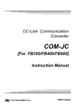
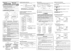
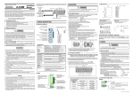
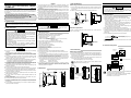
NOTICE CC-Link Communication Converter All Rights Reserved, Copyright © 2005, RKC INSTRUMENT INC. IMR01Y01-E5 Thank you for purchasing this RKC product. In order to achieve maximum performance and ensure proper operation of your new instrument, carefully read all the instructions in the manual. Please place this manual in a convenient location for easy reference. This manual describes the mounting, wiring and specifications only. For detailed handling procedures and operations, refer to separate COM-JC [For FB100/FB400/FB900] Instruction Manual (IMR01Y06-E). The manual can be downloaded from the official RKC website: http://www.rkcinst.com/english/manual_load.htm. z This manual assumes that the reader has a fundamental knowledge of the principles of electricity, process control, computer technology and communications. z The figures, diagrams and numeric values used in this manual are only for purpose z z z z z of illustration. RKC is not responsible for any damage or injury that is caused as a result of using this instrument, instrument failure or indirect damage. RKC is not responsible for any damage and/or injury resulting from the use of instruments made by imitating this instrument. Periodic maintenance is required for safe and proper operation of this instrument. Some components have a limited service life, or characteristics that change over time. Every effort has been made to ensure accuracy of all information contained herein. RKC makes no warranty expressed or implied, with respect to the accuracy of the information. The information in this manual is subject to change without prior notice. No portion of this document may be reprinted, modified, copied, transmitted, digitized, stored, processed or retrieved through any mechanical, electronic, optical or other means without prior written approval from RKC. 1.3 DIN Rail Mounting Mounting procedures 2. WIRING 1. Pull down the mounting bracket at the bottom of the module (A). Attach the hooks on the top of the module to the DIN rail and push the lower section into place on the DIN rail (B). 2. Slide the mounting bracket up to secure the module to the DIN rail (C). DIN rail Product Check (B) Push COM-JC [For FB100/FB400/FB900] Installation Manual (IMR01Y01-E5)....................1 COM-JC [For FB100/FB400/FB900] Quick Instruction Manual (IMR01Y11-E).........1 COM-JC [For FB100/FB400/FB900] Communication Data List (IMR01Y16-E) ........1 1. MOUNTING Mounting bracket ! Safety Precautions WARNING z This product is intended for use with industrial machines, test and measuring equipment. (It is not designed for use with medical equipment and nuclear energy.) z This is a Class A instrument. In a domestic environment, this instrument may cause radio interference, in which case the user may be required to take additional measures. z This instrument is protected from electric shock by reinforced insulation. Provide reinforced insulation between the wire for the input signal and the wires for instrument power supply, source of power and loads. z Be sure to provide an appropriate surge control circuit respectively for the following: − If input/output or signal lines within the building are longer than 30 meters. − If input/output or signal lines leave the building, regardless the length. z This instrument is designed for installation in an enclosed instrumentation panel. All high-voltage connections such as power supply terminals must be enclosed in the instrumentation panel to avoid electric shock by operating personnel. z All precautions described in this manual should be taken to avoid damage to the instrument or equipment. z All wiring must be in accordance with local codes and regulations. z To prevent instrument damage or failure, protect the power line and the input/output lines from high currents with a protection device such as fuse, circuit breaker, etc. z Prevent metal fragments or lead wire scraps from falling inside instrument case to avoid electric shock, fire or malfunction. z Tighten each terminal screw to the specified torque found in the manual to avoid electric shock, fire or malfunction. z For proper operation of this instrument, provide adequate ventilation for heat dispensation. z Do not connect wires to unused terminals as this will interfere with proper operation of the instrument. z Turn off the power supply before cleaning the instrument. z Do not use a volatile solvent such as paint thinner to clean the instrument. Deformation or discoloration will occur. Use a soft, dry cloth to remove stains from the instrument. z To avoid damage to instrument display, do not rub with an abrasive material or push front panel with a hard object. (1) This instrument is intended to be used under the following environmental conditions. (IEC61010-1) [OVERVOLTAGE CATEGORY II, POLLUTION DEGREE 2] (2) Use this instrument within the following environment conditions: • Allowable ambient temperature: −10 to +50 °C • Allowable ambient humidity: 5 to 95 % RH (Absolute humidity: MAX. W. C 29.3 g/m3 dry air at 101.3 kPa) • Installation environment conditions: Indoor use Altitude up to 2000 m (3) Avoid the following conditions when selecting the mounting location: • Rapid changes in ambient temperature which may cause condensation. • Corrosive or inflammable gases. • Direct vibration or shock to the mainframe. • Water, oil, chemicals, vapor or steam splashes. • Excessive dust, salt or iron particles. • Excessive induction noise, static electricity, magnetic fields or noise. • Direct air flow from an air conditioner. • Exposure to direct sunlight. • Excessive heat accumulation. (4) Mount this instrument in the panel considering the following conditions: • Ensure at least 50 mm space on top and bottom of the instrument for maintenance and environmental reasons. • Do not mount this instrument directly above equipment that generates large amount of heat (heaters, transformers, semi-conductor functional devices, large-wattage resistors). • If the ambient temperature rises above 50 °C, cool this instrument with a forced air fan, cooler, etc. Cooled air should not blow directly on this instrument. • In order to improve safety and the immunity to withstand noise, mount this instrument as far away as possible from high voltage equipment, power lines, and rotating machinery. High voltage equipment: Do not mount within the same panel. Power lines: Separate at least 200 mm. Rotating machinery: Separate as far as possible. (5) If this instrument is permanently connected to equipment, it is important to include a switch or circuit-breaker into the installation. This should be in close proximity to the equipment and within easy reach of the operator. It should be marked as the disconnecting device for the equipment. WARNING To prevent electric shock or instrument failure, do not turn on the power until all wiring is completed. Make sure that the wiring is correct before applying power to the instrument. Removal procedures Pull down a mounting bracket with a blade screwdriver (A). Lift the module from bottom, and take it off (B). • To avoid noise induction, keep communication signal wire away from instrument power line, load lines and power lines of other electric equipment. • If there is electrical noise in the vicinity of the instrument that could affect operation, use a noise filter. − Shorten the distance between the twisted power supply wire pitches to achieve the most effective noise reduction. − Always install the noise filter on a grounded panel. Minimize the wiring distance between the noise filter output and the instrument power supply terminals to achieve the most effective noise reduction. − Do not connect fuses or switches to the noise filter output wiring as this will reduce the effectiveness of the noise filter. • Power supply wiring must be twisted and have a low voltage drop. • For an instrument with 24 V power supply, supply power from a SELV circuit. • A suitable power supply should be considered in end-use equipment. The power supply must be in compliance with a limited-energy circuits (maximum available current of 8 A). • Use the solderless terminal appropriate to the screw size (M3). Recommended tightening torque: 5.9 mm or less 0.4 N⋅m (4 kgf⋅cm) 3.2 mm or more • Make sure that the any wiring such as solderless terminal is not in contact with the adjoining terminals. (B) Lift and take off 2.2 Terminal Configuration (A) Pull down Controller communication 1.4 Panel Mounting Mounting procedures Upper-side terminal RS-485 T/R(A) 1. Pull down the mounting bracket (A) until locked and that a mounting hole appears. 2. Prepare one mounting bracket per module (B) sold separately (KSRX-55) and then insert it in the rear of the terminal board at top of the module until locked but a mounting hole does not disappear. 3. Mount each module directly on the panel with screws which are inserted in the mounting holes of the top and bottom mounting brackets. Recommended tightening torque: 0.3 N⋅m (3 kgf⋅cm) 3 1.2 Dimensions 6 5 1 5 SG 4 4 : The part of internal wiring Power supply Mounting dimensions 2 7 The customer needs to provide the M3 size screws. Select the screw length that matches the mounting panel. (B) Insert 1 T/R(B) 11 10 14 9 13 9 8 Ground 12 8 12 (Unit: mm) + DC 24 V − Lower-side terminal FG (Unit: mm) 109.5 9.5 3 30 Mounting holes Mounting bracket (Sold separately) (KSRX-55) M3 78 CAUTION 1.1 Mounting Cautions 125 z An external protection device must be installed if failure of this instrument could result in damage to the instrument, equipment or injury to personnel. z All wiring must be completed before power is turned on to prevent electric shock, fire or damage to instrument and equipment. z This instrument must be used in accordance with the specifications to prevent fire or damage to instrument and equipment. z This instrument is not intended for use in locations subject to flammable or explosive gases. z Do not touch high-voltage connections such as power supply terminals, etc. to avoid electric shock. z RKC is not responsible if this instrument is repaired, modified or disassembled by other than factory-approved personnel. Malfunction can occur and warranty is void under these conditions. 5 ! (C) Locked (A) Pull down WARNING To prevent electric shock or instrument failure, always turn off the power before mounting or removing the instrument. ! 2.1 Wiring Cautions 130.5 ± 0.2 COM-JC Installation [For FB100/FB400/FB900] Manual (A) Pull down • As controller communication terminal No. 1, 4 and 5 are internally connected to terminal No. 3, 6 and 7, any terminals can be used. • As ground and power supply terminal No. 8, 9 and 12 are internally connected to terminal No. 10, 11 and 14, any terminals can be used. • Terminal No. 2 and 13 is not used. Connection diagram 2.3 Connection to PLC Method to connect z Relationship between number of occupied station/extended cyclic and number of controller connection Always connect a termination resistor between the DA and DB terminals of the module to be located at the far end. Termination resistor: 110 Ω ± 5 % 1/2 W The PLC (master station) and COM-JC make multi-drop connection in CC-Link dedicated cable Ver. 1.10. Master station PLC Master station COM-JC TR Termination resistor COM-JC Number of occupied station/ extended cyclic Number of maximum connection of controller 1 station occupied 1 time 2 controllers COM-JC 4 stations occupied 1 time 16 controllers 4 stations occupied 2 times 31 controllers DA DA DA DB DB DB DG DG DG SLD SLD SLD FG FG CC-Link dedicated cable Ver.1.10 FG CC-Link dedicated cable Ver.1.10 Termination resistor TR TR: Termination resistor Up to 61 stations Up to 64 stations: 1 station occupied 1 time Station to station cable length: 20 cm or more Connection diagram Communication speed and maximum transmitter distance Communication speed Station to station cable length COM-JC Maximum transmitter distance (maximum length of network) 10 Mbps 100 m 5 Mbps 160 m 2.5 Mbps Conduct wiring between the COM-JC and controller (FB100/400/900) as shown in the following. (When conducting wiring to the FB100/400/900, always conduct wiring to the Communication 1 terminal.) (+) 400 m 20 cm or more 625 kbps 900 m 156 kbps 1200 m SG 4 (−) R1 25 SG 26 T/R (A) T/R (B) 5 27 T/R (B) Terminal No. Signal name Symbol Cable color 1 Data A DA Blue 2 Data B DB White (+) 3 Data ground DG Yellow 4 Shield SLD Grounding wire (Shield) 5 Frame ground FG ⎯ FB400/900 SD RUN FAIL (−) 26 T/R (A) Communication terminals of controller (Communication 1 side) Terminal No. Symbol FB100 FB400/900 13 25 SG 14 26 T/R (A) 15 27 T/R (B) 27 T/R (B) R2 1: DA 2: DB 3: DG 4: SLD 5: FG Terminal screws Screws size: M3 Recommended tightening torque: 0.4 Nxm (4 kgf⋅cm) RUN Communication terminals (communication 1 side) or disconnected by the switch. (Factory set value: Termination resistor connected) SD RD [Red] • • • • [Green] • • • When instrument abnormally: Turns on CC-Link setting error: Turns on CC-Link operation error: Flashes slowly CC-Link setting is changed: Flashes rapidly When normally: Turns on Operation error: Flashes slowly During controller communication initialization: Flashes rapidly [Green] During CC-Link data send: Turns on [Green] During CC-Link data receive: Turns on COM. PORT PLC (Mitsubishi Electric MELSEC Q series) CC-Link Controller communication (RS-485: Modbus) Modbus-RTU Communication speed: 9600 bps, 19200 bps, 38400 bps Data bit configuration: Data 8-bit, Without parity, Stop 1-bit General specifications Power supply voltage: 24 V DC Power supply voltage range: 21.6 V DC to 26.4 V DC 120 mA max. (at 24 V DC) Rush current: 12 A or less Allowable ambient temperature range: −10 to +50 °C Allowable ambient humidity range: 5 to 95 %RH (Non condensing) (Absolute humidity: MAX.W.C 29.3 g/m3 dry air at 101.3 kPa) Installation environment conditions: Indoor use Altitude up to 2000 m Weight: Approx. 220 g Standard Safety standard: CE marking: UL: UL61010-1 cUL: CAN/CSA-C22.2 No. 61010-1 LVD: EN61010-1 EMC: EN61326-1 C-Tick: EN55011 FB100 FB400 FB900 FB100 FB400 FB900 FB100 FB400 FB900 1 2 31 FB100, FB400 or FB900 (Up to 31 controllers) CC-Link Communication converter COM-JC Power supply (24 V DC) Terminal base Mainframe 5. MODEL CODE Set the station number for CC-Link COM- JC * 01 - Set the communication speed for CC-Link • Set the number of occupied station/extension cyclic for CC-Link • Set the communication speed for controller communication z Others Terminal cover Mounting bracket Do not ground the instrument together with other equipment. In addition, use grounding wires with a cross section of 2.0 mm2 or more. (Ground resistance: 100 ohm or less) Terminals for PLC (Master) connection z Switches Station number setting switch CC-Link communication speed setting switch Dip switch 2.5 System Configuration Example Ground both ends of the shield wire on the twisted pair cable via the SLD or FG terminal of each module. In addition, the SLD terminal is internally connected with the FG terminal. Based on RS-485, EIA standard Protocol: z CC-Link connection terminals provided by the customer. • The termination resistor existing within the COM-JC can be connected The CC-Link connecting terminal cannot do on-line installation or dismount for terminal block of dismount impossibility. The device cannot be replaced unless the link is set offline. In addition, FG (frame ground) terminal of terminal number 5 is FG in a CC-Link function, and it is not FG of instrument all. For cable specifications, connection method and vendor, refer to the website of CC-Link Partner Association. FAIL (+) • The cable and termination resistor for external connection must be CC-Link connection terminals Indication lamps z Indication lamps 25 SG Maxmum connections: 31 controllers Interface: Power consumption: y y y R1: Internal termination resistor (120 Ω 1/2 W) R2: Termination resistor for external connection (Example: 120 Ω 1/2 W) If communication errors occur frequently due to the operation environment or the communication distance, connect termination resistors. Left side view RD Communication terminals (communication 1 side) Terminal base CC-Link communication speed setting switch (−) Shielded twisted pair wire Terminal numbers and signal details URL: http://www.cc-link.org/ Terminal cover Front view T/R (A) 1 Controller communication Maximum connections: 31 controllers (FB100/400/900) Mounting bracket FB400/900 Paired wire RS-485 Mainframe Dip switch CC-Link connection terminals (COM.PORT) Protocol: CC-Link Ver. 2.00/Ver. 1.10 Communication speed: 156 kbps, 625 kbps, 2.5 Mbps, 5 Mbps, 10 Mbps Station number: 1 to 61 (4 stations occupied 1 time, 4 stations occupied 2 times) 1 to 64 (1 station occupied 1 time) Connection cable: CC-Link dedicated cable Ver. 1.10 Terminal base Terminal cover Station number setting switch 2.4 Connection to the Controllers CC-Link dedicated cable Ver.1.10 CC-Link communication Number of occupied station/extended cyclic and CC-Link version: CC-Link Ver. 1.10: 1 station occupied 1 time, 4 stations occupied 1 time CC-Link Ver. 2.00: 4 stations occupied 2 times 3. PARTS DESCRIPTION Indication lamps 4. SPECIFICATIONS Terminal covers above and below the COM-JC • Used for the DIN rail mounting • When panel mounted, two mounting brackets are required for the upper and lower sides (one required for the upper side: separately sold). Part of the terminal and base of COM-JC (There is the termination resistor transfer switch in the inside of terminal base) Part of the mainframe of COM-JC (1) (2) (1) Corresponding to the RKC temperature controller 01: FB100/400/900 (2) RUN/STOP logic selection 1: 0: RUN 1: STOP 2: 0: STOP 1: RUN CC-Link is a registered trademark of Mitsubishi Electric Co. Ltd. Modbus is a registered trademark of Schneider Electric. Company names and product names used in this manual are the trademarks or registered trademarks of the respective companies. ® RKC INSTRUMENT INC. The first edition: The fifth edition: JAN. 2005 [IMQ00] SEP. 2011 [IMQ00] HEADQUARTERS: 16-6, KUGAHARA 5-CHOME, OHTA-KU TOKYO 146-8515 JAPAN PHONE: 03-3751-9799 (+81 3 3751 9799) E-mail: [email protected] FAX: 03-3751-8585 (+81 3 3751 8585) Website: http://www.rkcinst.com/ SEP. 2011