1
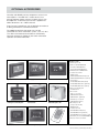
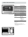
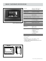
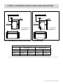
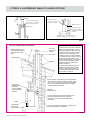
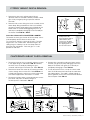
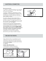
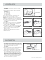
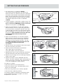
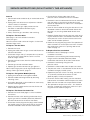
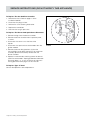
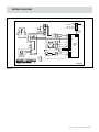
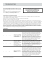
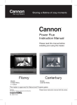
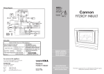
Inbuilt Heater
Instruction Manual
Please read this manual before
installing and using this heater.
Canterbury
Distributor
This appliance is designed, manufactured and distributed by:
Tel: 1300 727 421
Fitzroy
Please leave instruction manual with the owner
Contents
Page
Warranty
2
Safety Warnings
3
OperatiON
4
Optional Accessories
5
inbuilt: Fitzroy specifications
6
inbuilt: Canterbury specifications
7
Fitzroy & Canterbury Inbuilt Installation Instructions
8–9
Fitzroy & Canterbury Inbuilt Fluing options
10
Fitzroy Inbuilt Fascia Removal
11
Canterbury Inbuilt Fascia Removal
11
Electrical Connection & Sealing the Fascia
12
Log Installation & GAS CONNECTION
13
SETTING THE GAS PRESSURE
14
Service Instructions
15 –16
Wiring Diagram
17
Troubleshooting
18 – 19
warranty
The benefits conferred by this warranty are in addition
to all other rights and remedies in respect of the product
that consumers have under the Trade Practices Act and
similar laws of the States and Territories.
We warrant this Cannon appliance to be free of defects in
materials, workmanship and manufacturing to the original
purchaser for 2 years, (10 years on the heat exchanger)
from the date of original purchase. We will, at our option
and subject to the terms of this warranty, repair or replace
free of charge this Cannon appliance or any component
part, which upon examination by us or our repair agent
is found to be defective in materials, workmanship or
manufacturing. However, this warranty does not cover
any consumables (if any).
DO NOT operate this appliance before reading the
instruction booklet.
DO NOT place articles on or against this appliance.
DO NOT store chemicals or flammable
materials, or spray aerosols near this appliance.
The purchaser must present the original purchase receipt
to us when making any claim under this warranty.
DO NOT operate with panels, covers or guards
removed from this appliance.
This warranty will not apply if: (i) a compliance label or
serial number (as the case may be) has been removed
from the appliance or rendered illegible; (ii) the appliance
has been subject to misuse, abuse, accident, incorrect
installation or non-domestic use; (iii) the appliance has
been modified, tampered with or repaired by a person
other than our authorised repair agent; (iv) the appliance
is re-installed/relocated during the warranty period.
Don’t risk your appliance warranty.
The purchaser is responsible for all travelling expenses
if the purchaser requests any repair be carried out
at a place outside areas normally serviced by our
repair agents.
Should you require service on this appliance, please
contact our service department on 1300 727 421.
Enter the details of the date installed and the
Compliance Certificate number in the appropriate
area on the rear page of this manual.
2 | Cannon Fitzroy / Canterbury Inbuilt
Only a licensed person will give you a
Compliance Certificate, showing that the work
complies with all the relevant standards.
And only a licensed person will have insurance
protecting their workmanship for 6 years.
So make sure you use a licensed person to install this
appliance and ask for your Compliance Certificate
to ensure the manufacturers
appliance warranty will be honoured.
Safety Warnings
Please read this manual before installing and using
the heater.
8.If removed, the glass window must be put back onto
the unit prior to operating the heater.
Safety Warnings
9.Installation and repairs should be performed by a
licensed service person only, refer to back of brochure
for service number.
1.Improper installation, adjustment, alteration, service
or maintenance can cause injury or property damage.
Refer to the sections of this manual for correct procedures, or consult with place of purchase, a licensed
plumber, a gas supplier or the CANNON distributor
listed in this manual.
2.Install the heater only in locations that are referred to
in the installation instructions. Do not build the heater
into bookcases, walls or enclosures (combustible
materials) without the use of a Mock Fireplace kit.
3. Due to high temperatures the room heater should be
located out of traffic and away from:
Furniture and draperies
Combustible materials
Gasoline and other flammable liquids
Do not place clothing or other flammable
material on or near the heater.
4. Keep curtains*, clothes, furniture and other
flammable materials at least 900mm from front
and sides of heater.
* At the owner’s discretion curtain clearance can
be less than 900mm as long as they are restrained
from the front, top and sides of the heater.
The manufacturer takes no responsibility if curtain
clearance is less than 900mm and not restrained.
5.Children and adults should be alerted to the hazard
of high surface temperature and should take care to
avoid burns or clothing ignition.
This appliance is not intended for use by
persons (including children) with reduced
physical, sensory or mental capabilities or lack
of experience and knowledge, unless they have
been given supervision or instruction concerning use of the appliance by a person responsible
for their safety. Children should be supervised to
ensure that they do not play with the appliance.
6.Never attempt to burn paper or any other material in
the heater.
7. Do not place articles on or against this appliance.
Do not use or store flammable materials near
this appliance.
Do not spray aerosols in the vicinity of this
appliance while it is in operation
Do not modify this appliance.
10.For installation into a non-combustble fireplace, i.e
masonry or brick or into a mock fireplace, i.e. timber
or plasterboard, the chimney and base should be
of sound construction and be free from cracks and
holes (to ensure that sufficient flue draught can
be generated).
Note: when installing into a mock fireplace a
mock fireplace installation kit must be used.
(Part No. MOCKKITUNI)
11.The heater must be properly installed in a working
chimney or mock fireplace with flue. Operation of this
heater, when not connected into a working chimney or
a properly installed and maintained flueing system can
result in carbon monoxide (CO) poisoning and possible death.
12.Testing the effectiveness of the flue: Before testing the
flue confirm air vents are unobstructed. If an exhaust
fan or other heating appliances are present switch
them on. This is to test that there is no interaction
between the Cannon heater and other appliances.
efer to Australian Standard Gas Installations AS 5601.
R
For ‘air movement not to affect appliance’ see clause 5.3.1.
For ‘air supply to appliance’ see clause 5.4.1.
For ‘ventilation requirements’ see clause 5.4.3.
13.The appliance should be inspected prior to use,
with regular inspections (annually) to be made by a
licensed service person. It is important that circulating
air passageways of the appliance be kept clean, dirt
and lint free, for safe and efficient operation of
the heater.
14.On first lighting your heater an odour may be emitted
due to its new condition. This is quite normal and will
disappear after a few hours use at the maximum
control position.
Important: When this heater is operating the mesh
guard/glass front is hot. The mesh guard, or glass
front, is fitted to this appliance to reduce the risk of
fire or injury from burns and no part of it should be
permanently removed. For protection of young children or the infirm, a secondary guard is required.
This appliance meets the following standards:
Standards Australia
AS/NZS 3100
AS 5601
AS 4553:2008
Cannon Fitzroy / Canterbury Inbuilt | 3
OperatiON
Operating Instructions
Plug the power cord into the wall socket and turn on the
power to the heater (FIG 1). Alternatively, switch on the
isolation switch and circuit breaker at the main switchboard if the heater has fixed wiring. Refrain from using
an extension cord.
User controls FIG 2.
When there is power available to the heater and it is in
the OFF or Standby mode, a red LED located inside the
ON/OFF button will flash twice and will extinguish after
approximately 3 seconds and then repeat this cycle
continuously.
To Turn the heater ON press the ON/OFF button once.
• T
he LED will illuminate and an audible beep will sound
but there will be approximately 5 seconds delay
before the ignition system commences. On successful ignition the heater will operate on Low Fire and
Low Fan for approximately 3 minutes then will switch
to selected setting (if already chosen, otherwise will
switch to Medium settings automatically).
• T
he LED will extinguish approximately 30 seconds
following the ignition startup.
• S
elect the desired heating level by pressing the LOW,
MEDIUM or HIGH button once as required.
• L
OW is LOW heat and LOW speed fan. High is High
heat and High speed fan.
• T
o turn the heater OFF press the ON/OFF button
once. An audible beep will sound twice to indicate
the heater is off. The burner will extinguish but the fan
will continue to operate for approximately 3 minutes.
Remember that the fan will continue to operate for
approximately 3 minutes after the OFF button has
been pressed but you can turn the heater ON again
without having to wait for the fan to stop operating.
• If the ignition system fails to ignite or keep the burner
alight, the system will beep 4 times and go into
safe shutdown mode. It will beep 4 times every 30
seconds to alert you to the fact. Press the ON/OFF
button once to restart the heater during this time.
Wait at least 20 seconds before attempting to turn the
heater on.
• If there is an interruption to the power supply the
heater will fail safely and switch off. When the power
supply has been restored adopt the 20 seconds
waiting rule before turning the heater ON.
Cleaning
All cleaning should be carried out when the heater is
cold. Normally the heater should only need wiping with a
lint-free damp cloth. Any stubborn stains can be removed
with a nonabrasive spray on cleaner. If an abrasive
cleaner is used the paint finish will be damaged.
For heaters fitted with the glass front: All cleaning should
be carried out when the heater is cold. Clean the outer
glass with a mild liquid or spray on glass cleaner. Do not
use harsh abrasive cleaners or sharp metal scrapers to
clean the heater glass front since they can scratch the
surface, which may result in shattering of the glass.
Internally the heater should only be cleaned by an
authorised service person.
If your heater requires attention contact your supplier
or an authorised service person.
Flame Characteristics
The heater flame should be stable, not lifting from the
burner. The logs should glow after approximately 15
minutes operation on HIGH setting.
The heater is a fuel effect unit and is designed to
operate with luminous flames and may exhibit slight
carbon deposit on the logs. If there is any excess carbon
build-up on logs, or the burner flame is unstable, contact
Sampford IXL in your state.
Important
The appliance should be inspected before use and
at least annually by an authorised service person.
More frequent cleaning may be required due to
excessive lint build-up from carpeting, bedding
materials, pet hair, etc.
It is imperative that control compartments, burners
and circulating air passage ways of the appliance
be kept clean.
Do not use this fire if the glass is cracked or with
the safety screen removed.
Do not use fire with broken or missing logs.
ON / OFF
LOW
MEDIUM
HIGH
FIG 1
4 | Cannon Fitzroy / Canterbury Inbuilt
FIG 2
Optional Accessories
Versatility and flexibility are key components of our installation options. If installed into a shallow recess or an
existing fireplace, elegant spacers will eliminate any size
discrepancies. To enhance your Cannon’s appearance
add a decorative 3 or 4 sided surround.
Every Cannon heater brings you the optional convenience
of being controlled via a remote thermostat.
For added convenience the heater can now be
connected to a home automation system, such as C-bus.
This allows the heater to be turned on or off remotely
(low heat setting only). Speak to your home automation
specialist for further information.
Spacer kit
Fitzroy glass kit
3 sided surround kit
Fitzroy freestanding kit
Console kit
Mock fireplace kit
4 sided surround kit
Canterbury mesh guard
Remote thermostat
Product codes
• 50 mm spacer kit
CANT model BSPACERE-B
FITZ Black BSPACERX-B
FITZ Platinum BSPACERX-P
• FITZ Glass kit: FITZDGKITX-B
• 3 sided surround kit:
CANT model
CANTSURROUND3SX-B (black)
CANTSURROUND3SX-S (S/Steel)
FITZ models
FITZSURROUND3SX-B (black)
FITZSURROUND3SX-P (platinum)
FITZSURROUND3SX-S (S/Steel)
• Fitzroy freestanding kit:
FITZFSKITX-B
• Console Kit:
Fitzroy console kit:
CONSFITZX-B (black)
CONSFITZX-P (platinum)
Canterbury console kit:
CONSCANT-B (black)
• Mock fireplace kit
(all open flue inbuilts):
MOCKKITUNI
• 4 sided surround:
SURROUND4SX-B (black)
SURROUND4SX-P (platinum)
SURROUND4SX-S (stainless steel)
• Canterbury mesh kit: CANTIBMG-B
• Remote Thermostat: RTKIT
Cannon Fitzroy / Canterbury Inbuilt | 5
inbuilt: Fitzroy specifications
Cannon Fitzroy Inbuilt
Gas type
Natural or Propane gas,
as indicated on data label
Gas consumption
26.0 MJ/hr
Energy output
5.98 kW / 21.45 MJ/hr
Energy star rating
4.05 stars
Heater type
Gas space heater approved
to AS 4553:2008
Operating pressure
(at burner high setting)
Natural gas 0.75 kPa
Propane gas 2.65 kPa
Gas regulator
Integral part of controller
Min. inlet pressure
.13 kPa (NG)
1
2.75 kPa (Propane)
Fan
3 speed
Ignition
Electronic direct spark
Power requirement
240 VAC 10 Amp
Power consumption
90 VA maximum
Minimum cavity
dimensions
Height 605 mm*
Width 700 mm*
Depth 405 mm*
Optional accessories
• Glass front
• Remote thermostat
• Spacer kit
• 3 sided surround
• 4 sided surround
• Console kit
Overall dimensions
Refer to FIG 3
*For installation into a non-combustible fireplace, ie:
masonry or brick
Please Note:
• When installing into a mock fireplace a mock
fireplace installation kit must be used.
• The data label is located in the fan chamber. Access
by removing fascia.
FIG 3 Front View and Side View
6 | Cannon Fitzroy / Canterbury Inbuilt
8 mm
600 mm
50 mm 347 mm
651 mm
808 mm
inbuilt: Canterbury specifications
Gas type
Natural or Propane gas, as
indicated on data label
Gas consumption
26 MJ/hr input
Energy output
5.98 kW / 21.45 MJ/hr
Energy star rating
4.05 stars
Heater type
Gas space heater approved to
AS4553:2008
Operating pressure
Natural gas: 0.75 kPa
(at burner high setting) Propane gas 2.65 kPa
Cannon Canterbury Inbuilt
Ceiling
Gas regulator
Integral part of controller
Min. inlet pressure
1.13 kPa (NG)
2.75 kPa (Propane)
Fan
3 speed
Ignition
Electronic direct spark
Power requirement
240 VAC 10 Amp
Power consumption
90 VA maximum
Minimum cavity
dimensions
Height 605mm*
Width 700mm
Depth 385mm
Optional accessories
• Safety mesh guard
• Remote thermostat
• Spacer kit
• 3 sided surround
• 4 sided surround
• Console kit
Overall dimensions
Refer to FIG 4
1000 mm min clearance
Mantle 300 mm min clearance
Rear wall
380 mm
900 mm min
clearance
50 mm
clearance
*For installation into a non-combustible fireplace, ie:
masonry or brick.
Please Note:
• When installing into a mock fireplace a mock
fireplace installation kit must be used.
• The data label is located in the fan chamber. Access
by removing fascia.
700 – 790 mm
690 mm
34 mm
600 mm
125 mm 298 mm
655 mm
850 mm
FIG 4 Front View and Side View
Cannon Fitzroy / Canterbury Inbuilt | 7
Fitzroy & Canterbury Inbuilt Installation Instructions
Overview
1. This appliance is to be installed by an authorised service person only.
2. This appliance shall be installed in accordance with the
manufacturer’s installation instructions, local gas fitting
regulations, municipal building codes, electrical wiring
regulations, and AS5601 the Australian Standard for
gas installations.
3. Remove the heater from the carton and remove
the four transit screws. Check that the heater is suitable for the gas available. Refer to the data label located
within the fan chamber (Bottom most area with fascia
removed). (Please dispose of packaging appropriately,
keep away from children).
Installation Tips
Test the operation of the chimney before installing the
new heater.
Any service requests resulting from incorrect installations are not covered by our warranty conditions
and these calls will result in charges, usually to the
end user, so please ensure that the installation and
commissioning has been satisfactorily carried out
before calling for any warranty service.
Please make sure that your customer is fully instructed on
how to operate the heater.
Clearances
For minimum clearances refer FIG 5 and FIG 6.
A clearance of 50 mm must be maintained between
the cabinet and the rear wall of the fireplace.
Ensure the minimum clearances to combustible
materials are maintained during installation, including
adequate space for the proper operation and servicing
of the heater. For clearances to furniture and curtains
refer to warning on page 3 (Safety Warnings)
CANNON heaters are high efficiency products with low
flue gas temperatures (typically 100°C) so if you are
replacing an older type radiant heater with a much higher
flue gas temperature (150°C or higher) make sure of the
integrity of the fireplace and chimney before installing the
new CANNON log fire.
Note: Ensure that the combustion air opening under the
heater is not obstructed.
A solid, levelled and smooth base is required
(fill gaps with fibreglass insulation if necessary).
Installation Into A Masonry/Brick Or Mock Fireplace
Avoid installing into large volume fireplaces and chimneys
and not fitting a flue.
We recommend cleaning or sweeping the chimney and
fireplace before the installation of the heater commences.
There must be a good seal around the heater, gas piping
and electrical cable rear entry to stop any leakage of
combustion products. Do not use adhesives or silicone
sealant, the heater must be able to be easily removed
if necessary.
Install a chimney plate and cowl to the chimney opening
using weatherproof mortar to common building practice.
Remove any curved fire wall that slopes too far forward
to the fireplace opening as it causes restriction to the flue
path above the heater flue outlet. Refer FIG 7 & FIG 8.
Make sure that the heater is fully commissioned and be
certain to conduct a test of the integrity of the flue operation, taking into account any influences created by range
hoods, exhaust fans, central heating, etc.
To avoid any unnecessary delays and inconvenience to
your customer please contact our Technical Services
Department on 1300 727 421 if the installation is unusual
or you have concerns with the installation and/or heater
operation before the installation commences.
8 | Cannon Fitzroy / Canterbury Inbuilt
The clearance is required for correct fluing of
the appliance. If the clearance is less than 50mm
a spacer kit must be fitted. The spacer can be
ordered from the Cannon distributor.
Both models FITZIB & CANTIB can be installed into a
masonry/brick fireplace or a mock fireplace. If installing into a mock fireplace a mock fireplace installation kit
MUST be used. The mock fireplace kit can be ordered
from the CANNON distributor. Order specification for the
part is ‘MOCKKITUNI’.
For installation into a masonry or brick fireplace WITH
a flue connection, refer FIG 9. For installation WITHOUT refer FIG 7 & FIG 8. After installation of the heater,
test the flue to confirm air vents are unobstructed. If an
exhaust fan or other heating/ventilation appliances are
present, switch them on. This is to test and ensure that
there is no interaction between the Cannon heater and
other appliances.
Refer to Australian Standard Gas Installations AS 5601:
For ‘air movement not to affect appliance’ see clause
5.3.1.
For ‘air supply to appliance’ see clause 5.4.1.
For ‘ventilation requirements’ see clause 5.4.3.
Fitzroy & Canterbury Inbuilt Installation Instructions
Ceiling
Ceiling
1000 mm min clearance
1000 mm min clearance
Mantle 300 mm min clearance
Mantle 300 mm min clearance
Rear wall
405 mm min
900 mm min
clearance
50 mm
clearance
For installations in
non combustible
enclosures.
700 – 780 mm
50 mm
clearance
For installations in
non combustible
enclosures.
700 – 790 mm
690 mm
808 mm
50 mm 347 mm
8 mm
850 mm
125 mm 298 mm
FIG 6 CANTIB-SDEEB
600 mm
651 mm
FIG 5 FITZIB-SMENB/FITZIB-SMEXB/FITZIB-SMEXP
Mock Fireplace Opening (Combustible materials)*
Fitzroy Inbuilt
34 mm
600 mm
690 mm
655 mm
900 mm min
clearance
Rear wall
380 mm
Canterbury Inbuilt
Max
Min
Max
Min
Height
650 mm
630 mm
654 mm
630 mm
Width
780 mm
731 mm
790 mm
731 mm
Depth
600 mm
520 mm**
550 mm
470 mm**
*If you have larger opening than the maximum height indicated, a surround kit is recommended. **Includes 50mm clearance between flue spigot and rear wall
Cannon Fitzroy / Canterbury Inbuilt | 9
Fitzroy & Canterbury Inbuilt FluEing options
Flue cowl. Approved to
AG604
200mm
min.
All gaps between
heater and fireplaces
need to be sealed.
Fasten and seal battle
plate to top of chimney
with waterproof mortar.
50mm clearance
Baffle plate
100mm
Seal gas pipe and
cable holes with a
suitable removeable
material
All gaps between heater bottom case
and base of fireplace to be sealed
FIG 7
FIG 8
For non-combustible installation
600mm between top of
cowl and nearest part of
roof. (Also refer to AS
5601)
Be careful!
Flue cowl
approved to
AG604
Flue clamp
Roof cladding
Flashing
Installing a flue on the shorter wall may
subject it to down draughts or reverse
air flows through the heater which can
be difficult to find a solution to. Always
adopt correct flue design practices.
In windy locations consider installation
of a powerflue version heater or at least
an anti down draught cowl to reduce
any flue operation problems. The heater
has been tested and should operate
satisfactorily with an optimum flue
length of 4.5 meters.
Exceeding this length may affect the
stability of the flame pattern and the
operation of the heater. Contact our
technical support department if any
further advice is required.
Seal heater
perimeter with
foam tape
or other suitable
easily removable
material.
Fit two lengths of vertical flue (1.8m) before fitting
any 45° bends. If bends are used, fit inside of flue
pipe. Use no more than two 45° bends in the total
flue run and maintain at least 250mm of straight
flue pipe between the bends.
Ø100mm
Single skin flue.
The flue must be rigid and self-supported. It is a
requirement that the heater has a slip flue
connection and can be removed without any
restrictions.
Heater
Install heater
onto a solid,
leveled base.
F1417 flue transition rectangular to 100mm round.
F2517 flue spigot is also required.
FIG 9
10 | Cannon Fitzroy / Canterbury Inbuilt
Fitzroy Inbuilt Fascia Removal
1.Remove the wire mesh grille by gently lifting it
upwards and then outwards. Similarly remove a fitted
glass kit by also gently lifting it upwards and then
outwards.
2.Remove 4 M5 screws fixing the fascia assembly to the
heater body. Bring the bottom of the fascia towards
you gently to partly disengage it from the body of the
heater. After it has been disengaged gently lift it up
vertically to completely disengage it from the body of
the heater. Refer FIG 10 & FIG11.
FIG 10
Inner Glass Removal For Both FITZIB & CANTIB
To fully remove the
fascia, unclip the switch
cable from the cable
connector on the PCB
and unclip the cable from
the clipping points on
the rear of the fascia.
To remove the inner glass loosen off all the clamp screws
and completely remove the one vertical side.
Try not to touch the front surface of the glass. To avoid
finger marks use suitable cloth. Remove the glass by
sliding the glass sideways out of the clamp and then
lifting out from the bottom. Place the glass in a safe
position for refit later.
FIG 11
Canterbury Inbuilt Fascia Removal
1.To remove the inner fascia assembly undo two screws
in the upper flange as indicated in FIG 12. Remove
the inner fascia assembly by holding the glass
surround and firmly pull it towards you. Refer FIG 13.
4.Remove the surround by pulling the lower section
towards you gently to partly disengage it from the
body of the heater, then gently lift it vertically to
completely disengage it. Refer FIG 16.
2.Remove the lower front cover by unscrewing two M5
screws through the air intake slots. Refer FIG 14 unit
is fitted with electronic swtiches ensure that the cable
cannot be trapped when the heater is installed.
5.To fully remove the fascia, unclip the switch cable
from the PCB connector and unclip the cable from
the clipping points. The cable is routed through a
plastic grommet which will have to be removed from
the base plate. Refer FIG 17.
3.To remove the front heater surround undo two screws
(one either side) from the bottom flange of
the front panel as indicated in FIG 15.
FIG 12
FIG 13
FIG 14
Grommet
FIG 15
FIG 16
FIG 17
Cannon Fitzroy / Canterbury Inbuilt | 11
Electrical Connection
Electrical Connection
Grommet
This appliance is designed to operate on 240V AC power
supply. Failure to operate unit at correct supply voltage
may create unsafe conditions.
The heater is supplied with a flexible power cord with
a plug fitted. A 10 Amp power point (socket) must be
located within 1.5m of the heater. For installations where
the power point is located outside of the enclosure,
locate the power cord in the fascia cut out on the left or
right hand side as required.
FIG 18
For a power supply connection located inside the
enclosure run the power cord through the cord access
located on the rear panel by pushing the cord access
plate from the bottom. The rubber grommet that is fitted
over the cord must be located correctly in the cut out of
the cord access plate. Refer FIG 18.
Restore the cord access plate to the original position
and seal with an appropriate removable material, this is
especially important when the installation is in a chimney
with no flue fitted to eliminate the possibility of any leakage of flue products into the room. A suitable double
pole isolation switch must be installed externally for
servicing or emergency shut down of the heater.
All fixed wiring must be installed by a suitably
qualified person and comply to the appropriate
electrical wiring rules and gas installation standards.
Sealing the Fascia
All gaps between heater case and fireplace are to be
sealed. Seal with foam tape around top and sides of
heater flange as required. (Do not apply sealing product
to fascia). Seal with fibreglass between bottom of heater
case and base of fireplace.
Refer FIG 19.
DO NOT SEAL WITH SILICON
If using a spacer to compensate for lack of
chimney depth ensure the tape is placed on
the outer rim of the spacer flange. Refer FIG 20.
Sealing tape applied
to edge of spacer to
seal against fireplace
Sealing tape to be
applied onto flanges of
rear of front surround
so as to seal against
fireplace brick wall
Sealing Tape
FIG 19
12 | Cannon Fitzroy / Canterbury Inbuilt
FIG 20
Log Installation
1. The burner is contained within the burner chamber.
Refer FIG 21.
2. Carefully unpack the log set. Logs are numbered
as follows:
#1 - Left front log
#2 - Left back log
#3 - Right front log
#4 - Right back log
Burner in base of
burner chamber
Position the four individually numbered logs in the
following order on the burner bed as shown in
FIG 22-25. The male locating pins on burner bed must
engage with corresponding holes in the individual logs.
FIG 21
a) Place log #1 into the 2 front left pins on the burner bed,
ensuring that the charring faces the front.
Refer FIG 22.
b) P
lace log #2 onto the 2 left back pins. Refer FIG 23.
c) Place log #3 on single right front pin, ensure fork
locates over log #2. Refer FIG 24.
d) P
lace log #4 on single right back pin, ensure left side
of log rests on depression in #3 log. Refer FIG 25.
3. Refit the inner glass, making sure not to over
tighten the screws.
FIG 22
FIG 23
FIG 24
FIG 25
4. Reconnect switch loom to the fascia switch set.
5. Replace the fascia.
GAS CONNECTION
1. Push the gas inlet access plate into the heater cabinet
and slide the heater into the fireplace ensuring that the
gas inlet pipe is fed through the hole located at the rear
right hand side of the heater at the bottom.
Refer FIG 26.
2. With heater in position, flanges should be hard against
masonry. Secure case flanges to the masonry.
Screw or bolt the flange through the slots provided.
3. Connect the gas supply pipe to the copper compression fitting provided (we recommend using a basin
wrench). Push the gas inlet plate down to its original
position and seal with an appropriate easily removable material. Do not seal with a silicone sealant as the
heater must be easily removable. Sealing is important
as it prevents any leakage of flue products into the
room. Test all connections for gas leaks.
Gas Inlet
Gas Connection
FIG 26
Cannon Fitzroy / Canterbury Inbuilt | 13
SETTING THE GAS PRESSURE
1. Gas valve layout is as indicated in FIG 27.
Pressures for ‘Burner high flame’ and ‘Burner low
flame’ are factory set, however if pressures need to be
checked or adjusted follow the procedures described
below. To check outlet pressure at burner ‘high flame’
and ‘low flame’ positions remove the plastic cap from
the regulatior adjustment location as indicated
in FIG 28.
2. The pressure point is closed with a captive screw. Turn
screw 6 revolutions anticlockwise to open the pressure
point as indicated on FIG 29 (a) and place manometer
tube over the test point as per FIG 30 (b).
Burner adjustment (Burner
‘Low flame’)
Pressure test point
with captive screw
Pressure adjustment (Burner ‘High
Flame’)
Plastic Cap
FIG 27
3. Switch the control buttons to ‘High flame’ position.
Wait for heater to switch to ‘High’ setting (time delay
on start up). Retain screwdriver in position and using
a spanner adjust the outer nut on the control to give a
pressure reading of 0.75 kPa for Natural Gas and 2.65
kPa for LPG. (Turn clockwise to increase pressure
and anticlockwise to decrease pressure).
Refer FIG 30.
4. Switch the control buttons to ‘Low flame’ position.
Retain spanner in position and using a screwdriver
adjust the central screw control to give a pressure
reading of 0.4 kPa for Natural Gas and 1.1 kPa for
LPG. (Turn clockwise to increase pressure and
anticlockwise to decrease pressure).
Refer FIG 31.
FIG 28
5. Remove spanner and screwdriver. Switch from high to
low to ensure settings are correct.
6. Switch heater off and remove the manometer
tube. Tighten pressure test point by
turning the captive screw fully clockwise.
7. Replace plastic cap. Ensure the little lug is positioned
towards lower right hand side to clear the controls.
(a)
(b)
FIG 29
Adjust
8. Refit the fascia, making sure not to damage the power
cord or switch cable.
9. Operate the heater on HIGH, MEDIUM and LOW
settings. The flame should be stable, no lifting from the
burner and the logs should glow after approximately
15 minutes of operation on HIGH setting.
If the flame is unstable:
• Check that the burner is located correctly.
Hold
FIG 30
• Check that the glass front is located correctly and is
against the sealing rope.
Hold
• Check that the gas pressure is correctly adjusted
• Check that flue is operating correctly
If the heater still does not operate to specification refer
to the troubleshooting chart on page 19, or contact
Sampford IXL in your state.
Adjust
FIG 31
14 | Cannon Fitzroy / Canterbury Inbuilt
Service Instructions (Do not modify this appliance)
General
1. Service work to be carried out by an authorised service
person only.
2. Unplug from wall socket or turn off power at isolation
switch if heater is hard wired.
3. Always shut off the gas supply and ensure that
the heater is cool before commencing any
service operations.
4. Always check for gas soundness after servicing.
To Replace The Inner Glass
Refer page 11 of the installation instructions.
Fit the new glass.
Note: Ensure the inside surface of the glass is clean and
free from finger marks.
To Replace The Gas Valve
1. Remove the fascia.
2. Unplug the cables from the gas control and disconnect
the earth connection.
3. Disconnect the gas inlet (½” compression nut) connection at entry gas control and the 16mm nut at the
outlet of the gas control.
4. Remove the three screws from the cradle retaining the
gas control.
4. Disconnect the silicone tubes from the fan
pressure switch. Remove fan from fan chamber.
5. Remove the venturi and bracket from the fan removed
from the heater. Insert and secure the venturi and
bracket on replacement fan. Note “TOP” should point
to air outlet of fan.
6. Insert fan into chamber ensuring that the venturi is not
disturbed. Locate fan onto male thread. Secure with
M5 wing nuts, ensuring rubber buffer locates over
thread.
7. Replace silicone tubes onto fan pressure switch ensuring that the black tube is connected to the black side
of the pressure switch. Check to make sure that the
tubes are not kinked or pinched.
8. Reconnect fan plug into plug carrier. Test operation of
room circulation fan and fan pressure switch. If heater
fails to light even when fan is spinning refer to fault
codes on page 18.
To Replace Fan Pressure Switch
1. Remove the fascia. Refer page 11 of the
installation instructions.
2. Remove the screw retaining the bracket mounting
the gas and fan controller (white box). Move
the bracket and controls to the front of the heater.
5. Remove gas control valve from heater.
3. Remove the connecting wiring from the
pressure switch.
6. Replace gas control and check for gas tightness.
4. Remove the silicone tubes from the pressure switch.
Note: check the gas pressure on high and low burner
settings. Refer “gas control”, page 14.
5. The pressure switch is secured onto the rear of the fan
chamber housing by two M5 screws.
To Replace The Ignition Module (Device)
6. Replace the pressure switch. For wiring, one wire to
“C” (common) and the other connect to “NO”
(Normally open). Polarity not important.
1. Unplug wire connectors from ignition module.
2. Remove module mounting bracket by removing
mounting screw.
3. Using pliers bend tabs so that module can come away
from the mounting bracket.
4. Replace ignition module and ensure that all wires are
reconnected correctly.
7. Re-attach silicone tubes making sure that the black
tube attaches to the black side of the pressure switch.
Make sure that the tubes are not pinched or kinked.
8. Test operation of fan pressure switch - turn heater on
low heat. If heater fails to light even when fan is spinning refer to fault codes on page 18.
To Replace The Room Circulation Fan
1. Remove the fascia. Refer page 11 of the installation
instructions.
2. Remove the front screw retaining the bracket mounting the gas and fan controller (white box). Move the
bracket and controls to the front of the heater.
Room Fan
Fan pressure switch
3. Disconnect the fan plug from the plug carrier. Remove
the two M5 wing nuts which locate the fan to the fan
chamber underside. Lower fan from male thread.
Gas & fan controller
Ignition module
Gas Valve
FIG 32
Cannon Fitzroy / Canterbury Inbuilt | 15
Service Instructions (Do not modify this appliance)
To Replace The Gas And Fan Controller
1.Remove the fascia. Refer to page 11 of the
installation booklet
2. Disconnect the plugs on box.
3.Remove the screw retaining the bracket
4.Replace the control box
5. Check and re-set gas pressures.
To Replace The Burner And Spark/Sense Electrodes
1. Remove the logs from the burner chamber.
2. Remove the burner chamber front inspection panel,
4 screws.
3. Disconnect the 16mm nut at the inlet of the
injector.
4. Disconnect the spark and sense electrodes from the
ignition module.
5. Remove the burner fixing brackets (2) from the
Left and Right hand side of the burner. Lift the burner
assembly upward and carefully remove from the
burner chamber.
6. Replace in reverse order, checking correct location of
spark/sense electrodes. Spark gap between electrode
and spark plate is 6 - 8 mm. Check for gas tightness.
For log placement refer page 13 of this manual.
To Replace Type “X”Cord
Contact Sampford IXL service department.
16 | Cannon Fitzroy / Canterbury Inbuilt
FIG 33
Wiring Diagram
ON/OFF
COILS
SWITCH
LOW BRN / LOW FAN
MED BRN / MED FAN
HIGH BRN / HIGH FAN
SPARK
ELECTRODE
EARTH
BLUE
RED
2 WAY
BROWN
BLUE
3 WAY
FLAME
SENSOR
SHEATHED
HIGH TEMP
DATA CABLE
MODULATING
VALVE F3691
BLACK
MOD1
WHITE
MOD2
RED
NC
BLUE
NO
IGNITION MODULE
F3833
240 V MAINS PLUG
RED
NATURALLY ASPIRATED
WIRING DIAGRAM
M
L
CONTROL
MODULE
F3828
A
N
BLUE
N
RED
C
1 WAY
PRESSURE
SWITCH F3327
ROOM AIR FAN
PURPLE
H
EARTH
4 WAY
C
GREY
BROWN
1.5 AMP[18]
ROOM FAN - F3594
2 WAY
RED
4 WAY
2 WAY
6 WAY
ORANGE
TH2
F3835 A
FIG 34
Cannon Fitzroy / Canterbury Inbuilt | 17
Troubleshooting
To check the operation of the heater’s electrical system
you will require a digital multimeter with the functions to
measure ac/dc voltage, continuity, resistance and microamps.
It is critical that the appliance is
earthed and that the active and
neutral are not reversed.
Please refer to page 19 for a detailed trouble shooting
table for Fitzroy and Canterbury Inbuilt heaters.
Cannon Fitzroy and Canterbury Inbuilt
There is a green and red LED on the ignition controller. These LEDs act as diagnostic aids when the heater safety
systems produce a safe shutdown condition.
Green LED: this is on when the flame is sensed at the flame sensor electrode.
Red LED: this flashes according to the fault code.
No LEDs means there is no power to the ignition module. Check that the heater switch is set to ON by pressing the
ON/OFF button. Check the supply voltage. Check the 1.5 Amp fuse, replace if necessary. It is critical that the appliance
is earthed and that the active and neutral are not reversed. Do not use an extension cord. This appliance is designed
to operate at 240V AC. Substantial voltage dips, or running the unit at voltages substantially lower than 240V AC may
cause nuisance shutdowns. If there is still a problem check the power supply plug from the white box with a multimeter (240V AC). If there is no power from this plug when the heater should be on, replace the white box. Remember to
re-test the gas pressures any time that the white box is changed. It is recommended that any callout to a customer’s
home should prompt the checking and resetting of the gas pressures.
Fault Codes
Long Short Morse Code
Meaning
1
Normal operation
2
2
1
0
1
2
2
—
Action
——•
Heater has attempted
to light, however it did
not sense flame within
the allowed time.
Check the gas supply to the unit is not switched off. Check
the gas pressures. Check the flame and spark electrode
connections and that they are positioned correctly. Ensure
that the spark is being produced at the spark electrode
tip, and is strong (clearly visible and around 6-8mm in
length). Adjust if necessary. The burner tray is earthed
through contact with the chassis. Check using a multimeter
between the earth pin (or earth tab) and the burner tray. If
the unit continues to spark after flame is present, ensure
that the supply voltage polarity is not reversed.
——••
Flame was established,
however the flame
electrode has sensed
that the flame has
become unstable and
has shutdown the gas.
Check that the flame sense electrode and the spark plate
are correctly positioned. Check the flame sense connections. Check that the flue is correctly constructed. Abnormally strong downdrafts can cause flame instability therefore it is recommended that an appropriate flue cowl is used
for windy areas. Improper gas pressures can also cause
issues. Check the gas pressures.
—••
Check the fan for dust build up and lint. Check that the
room air fan is spinning. Check that the pressure tubes are
connected correctly and not pinched or kinked. The black
tube should run from the black side of the pressure switch
Room fan (circulation
to the bottom tapping on the fan venturi. The clear tube
fan) pressure signal not should go from the light side of the pressure switch and to
detected.
the top tapping on the venturi. Make sure that the pressure
switch wires are connected correctly. One wire should be
to C (Common) and the other should be to NO (Normally
Open). If it still doesn’t work after checking the above,
change the pressure switch.
18 | Cannon Fitzroy / Canterbury Inbuilt
Troubleshooting
Fault Codes Continued
Long Short Morse Code
Meaning
3
———•
Check the fan for dust build up and lint. Check that the
room air fan is spinning. Check that the pressure tubes are
connected correctly and not pinched or kinked. The black
tube should run from the black side of the pressure switch
Room fan (circulation
to the bottom tapping on the fan venturi. The clear tube
fan) pressure signal has should go from the light side of the pressure switch and to
been interrupted.
the top tapping on the venturi. Make sure that the pressure
switch wires are connected correctly. One wire should be
to C (Common) and the other should be to NO (Normally
Open). If it still doesn’t work after checking the above,
change the pressure switch.
——••••••••
Check the fan for dust build up and lint. Check that the
room air fan is spinning. Check that the pressure tubes are
connected correctly and not pinched or kinked. The black
tube should run from the black side of the pressure switch
Room fan (circulation
to the bottom tapping on the fan venturi. The clear tube
fan) pressure switch
should go from the light side of the pressure switch and to
has not switched within
the top tapping on the venturi. Make sure that the pressure
hte expected time.
switch wires are connected correctly. One wire should be
to C (Common) and the other should be to NO (Normally
Open). If it still doesn’t work after checking the above,
change the pressure switch..
2
1
8
Action
Other Possible Faults
No gas to burner.
• The gas valve should open at the same time as the igniter sparks.
If there is no gas to the burner when this occurs check the
solenoid coils for continuity.
• Check that the gas pressure is present at the test point when the
spark is being generated.
• Check that there is gas to the inlet of the gas control.
Fuse blowing.
• If the fuse continues to blow check the solenoid coils for a signs of
them being shorted.
• Check the fan and wiring for short circuit.
Cannon Fitzroy / Canterbury Inbuilt | 19
COPY RATING LABEL HERE
Don’t Risk Your Appliance Warranty
Only a licensed person will give you a compliance certificate, showing that the work complies
with all the relevant standards. And only a licensed person will have insurance protecting their
workmanship for 6 years. So make sure you use a licensed person to install this appliance and ask
for your compliance certificate to ensure the manufacturers appliance warranty will be honoured.
Date installed:
Compliance Certificate No:
Installed by:
Gmk 10025
Gmk 10030
AS4553:2008
Part number:
F3841_A
20 | Cannon Fitzroy / Canterbury Inbuilt
For service to this appliance or spare parts
contact the CANNON distributor:
Sampford IXL – Spare Parts
Phone: 1300 727 421
Fax: 1300 727 425
Email: [email protected]