1
OPERATION MANUAL
OFFICE PRO 10
FIRST-CLASS MAIL PERMIT NO. 8390 LONG BEACH, CA
BUSINESS REPLY MAIL
DENSO SALES CALIFORNIA, INC.
3900 VIA ORO AVENUE
LONG BEACH CA 90810-9969
DENSO SALES CALIFORNIA, INC.
3900 Via Oro Avenue
Long Beach CA 90810-1868
800-264-9573 / 310-834-6352
www.movincool.com
NO POSTAGE
NECESSARY
IF MAILED
IN THE
UNITED STATES
Technical Services Department
DSCA P/N: LA990009-1184
GAC P/N: LA484007-1450
First Issue: March 2003
Printed in the U.S.A.
READ THIS MANUAL CAREFULLY FOR INSTRUCTIONS ON CORRECT
INSTALLATION AND USAGE, AND READ ALL SAFEGUARDS.
LIMITED WARRANTY
The aforesaid warranty is the only warranty made by DENSO with respect to the
Products and is in lieu of all obligations or liabilities on the part of DENSO for
damages arising out of or in connection with the sale, use or performance of the
Products, including, without limitation, any lost profits or any other consequential,
incidental, special or exemplary damages of any kind. DENSO DISCLAIMS ALL
OTHER WARRANTIES WITH REGARD TO THE PRODUCTS, INCLUDING ALL
IMPLIED WARRANTIES OF MERCHANTABILITY AND FITNESS FOR USE. THERE
ARE NO WARRANTIES WHICH EXTEND BEYOND THE DESCRIPTION CONTAINED HEREIN.
PURCHASE DATE: _____________________________________________________
© 2003 DENSO SALES CALIFORNIA, INC.
All rights reserved. This book may not be reproduced or copied, in
whole or in part, without the written permission of the publisher. DENSO
SALES CALIFORNIA, INC. reserves the right to make changes
without prior notice. MovinCool is a registerd trademark of
DENSO Corporation.
SERIAL NUMBER: _____________________________________________________
HERE
DETACH
This warranty does not cover defects or malfunctions which result from causes
beyond DENSO's control, including, without limitation, (i) unusual physical or
electrical stress; (ii) accident, neglect, abuse, misuse or other abnormal use; (iii)
failure to perform routine maintenance in accordance with DENSO'S recommended
procedures; (iv) normal wear and tear; (v) repairs or attempted repairs by an
unauthorized person; (vi) modifications or alterations to the Products; (vii) use with
supplies or devices not supplied or approved by DENSO; or (viii) improper
servicing. This warranty shall extend only to the original end-user and shall be void
if any labels or other identifying marks permanently affixed to Products when
shipped by DENSO are removed, altered, defaced or obliterated.
DENSO SALES CALIFORNIA, INC. ("DENSO") warrants its MOVINCOOL
Products only to the extent stated in its official written warranties. Unless
otherwise specifically provided in writing by DENSO, DENSO warrants to enduser that the Products shall be free of defects in materials or workmanship and will
function in accordance with DENSO's published specifications under ordinary intended use and service for a period of twelve (12) months after delivery to the enduser; provided, however, in the case of the compressor element of the Products
such warranty shall be for a period of thirty six (36) months after delivery to the
end-user. DENSO shall, at its sole option, repair or replace any defective Product
covered by this warranty. Such remedy shall be end-user's sole remedy with
respect to any particular defect in the Products.
OPERATION MANUAL
OFFICE PRO 10
i
ii
Table of Contents
FOREWORD ............................................................................................ 1
Definition of Terms .......................................................................... 1
GENERAL WARNINGS & CAUTIONS .................................................... 2
INVENTORY ............................................................................................ 3
INSTALLATION ....................................................................................... 4
Choosing an Installation Site .......................................................... 4
Moving the Unit ................................................................................ 5
Plugging in the Unit ......................................................................... 6
FEATURES .............................................................................................. 7
OPERATION ............................................................................................ 8
Control Panel ................................................................................... 8
Operating in COOL Mode ............................................................. 10
Operating in Fan Only Mode ......................................................... 10
Changing from Fan Only Mode to COOL Mode .......................... 10
Programming the Unit ................................................................... 11
To Set a Program ........................................................................... 12
Operating Modes ........................................................................... 16
Emptying the Drain Tank ............................................................... 17
Installing the Condenser Plenum and Reducer .......................... 18
Accessory Kit ................................................................................. 19
Accessory Kit Instructions ........................................................... 20
Remote Control (Optional) ............................................................ 22
Drain Pump Kit (Optional) ............................................................. 23
DAILY INSPECTION & MAINTENANCE .............................................. 24
Emptying the Drain Tank ............................................................... 24
Cleaning the Air Filters .................................................................. 24
Filter Removal Method .................................................................. 24
Filter Cleaning Method .................................................................. 25
In-Season/Off-Season Inspection & Maintenance ..................... 25
TROUBLESHOOTING ........................................................................... 26
Self-Diagnostic Codes .................................................................. 26
TECHNICAL SPECIFICATIONS ........................................................... 27
iii
iv
FOREWORD
Congratulations on purchasing the MovinCool portable air conditioner.
This manual explains how to install and operate the MovinCool Office
Pro 10 portable air conditioning unit. Please read this operation manual
thoroughly to familiarize yourself with the features of the unit and to
ensure years of reliable operation. You may also find it useful to keep
this operation manual on hand for reference.
Components and/or procedures are subject to change without prior
notice.
Definition of Terms
WARNING: Describes precautions that should be observed in
order to prevent injury to the user during installation or unit operation.
CAUTION: Describes precautions that should be observed in
order to prevent damage to the unit or its components, which may
occur during installation or unit operation if sufficient care is not
taken.
NOTE: Provides additional information that facilitates installation
or unit operation.
1
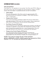
GENERAL WARNINGS & CAUTIONS
•
All electrical work, if necessary, should only be performed by
qualified electrical personnel. Repair to electrical components by
non-certified technicians may result in personal injury and/or
damage to the unit. All electrical components replaced must be
genuine MovinCool parts, purchased from an authorized reseller.
•
The proper electrical outlet for MovinCool units must be equipped
with a UL approved ground-fault breaker to prevent electrical shock
from the unit.
•
Because of potential safety hazards under a certain condition, we
strongly recommend against the use of an extension cord. However, if you still elect to use an extension cord, it is absolutely
necessary that it will be a UL listed, 3-wire grounding type appliance extension cord, having a 3-blade grounding plug and a 3-slot
receptacle that will plug into the appliance. The marked rating of
the extension cord should be 115 V, 15 A or equivalent.
•
The Office Pro 10 is equipped with a six (6) foot (1.8 meter) power
cord. If replacement, fixed location (hard wired) or power cord
lengthening (extension cord) cords are required, contact your
reseller or a qualified electrician for approved replacement methods.
•
Never fold or place heavy objects on the power cord. This could
result in damage to the power cord causing electrical shock or fire.
•
Do not place water or any other liquid on the unit. This can cause
damage to the unit and increase the risk of electrical shock.
•
Do not sit or stand on the unit.
2
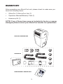
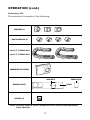
INVENTORY
After unpacking your MovinCool unit, please check to make sure you
have the following items:
•
Office Pro 10 MovinCool Unit (1)
•
Operation Manual/Warranty Card (1)
•
Accessory Kit (1)
NOTE: If any of these items were not included in the box or appear
damaged, please contact your MovinCool reseller for replacement.
OFFICE PRO 10 MOVINCOOL UNIT
ACCESSORY KIT
OPERATION MANUAL / WARRANTY CARD
3
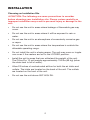
INSTALLATION
Choosing an Installation Site
CAUTION: The following are some precautions to consider
before choosing your installation site. Please review carefully as
improper installation may result in personal injury or damage to the
unit.
•
Do not use the unit in areas where leakage of flammable gas may
occur.
•
Do not use the unit in areas where it will be exposed to rain or
water.
•
Do not use the unit in an atmosphere of excessively corrosive gas
or vapor.
•
Do not use the unit in areas where the temperature is outside the
allowable operating range.
•
Do not install the unit in sloping areas. The unit may move or topple
over even if the casters are set to the LOCKED position.
•
Install the unit in areas that can withstand the weight of the unit.
The Office Pro 10 unit weighs approximately 130 lbs (59 kg) (when
the drain tank is full of water).
•
Allow 20 inches of unobstructed airflow for both the air inlets and
outlets. The inlets are located on the back of the unit. The outlets
are located on the front of the unit.
•
Do not use the unit above 95˚F 60% RH.
4
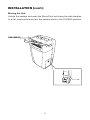
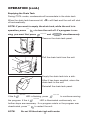
INSTALLATION (cont.)
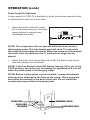
Moving the Unit
Unlock the casters and push the MovinCool unit using the side handles
to a flat, level surface and set the casters back to the LOCKED position.
SIDE HANDLES
5
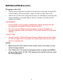
INSTALLATION (cont.)
Plugging in the Unit
•
Check the prongs and surface of the power cord plug for dust/dirt.
If dust and/or dirt are present, wipe off with a clean, dry cloth.
•
Check the power cord, plug and prongs for damage or excess play.
If any damage or excess play is found, contact your MovinCool
reseller for repair.
WARNING:
•
If the power cord or plug is damaged, repair should only be
performed by qualified electrical personnel.
•
Do not connect/disconnect the power cord or attempt to
operate buttons with wet hands. This could result in electrical
shock.
CAUTION:
•
The AC outlet (115 VAC Single Phase, 60Hz) needs to be rated
at 15A or higher. Do not share the outlet with any other instrument or equipment.
NOTE:
•
Make sure the AC outlet is free of dirt, dust, oil, water, or any
other foreign matter.
•
The Office Pro 10 model is equipped with an approved NEMA
plug configuration (5-15). The appropriate outlet must be used
for this plug type.
6
FEATURES
•
An electronic control panel, which allows the user to control the
unit’s operation easily.
•
Dual fan speeds (either HIGH or LOW) in both COOL and Fan
Only modes.
•
Digital display that indicates the temperature set point (either
Fahrenheit or Celsius) in which the COOL Mode will operate. This
is also the temperature the unit will try to maintain. The Temperature set point can be adjusted between LO 65ºF ~ 90ºF HI by the
key down/key up buttons ( / ).
•
A condensate drain
•
An automatic restart feature when the power is lost and regained.
The unit will return to the operating mode it was in prior to the loss
of power. Any preset program will be retained in the memory in the
event power loss occurs.
•
A programmable Clock/Timer function. This allows the user to
program a specific time of day that the unit will begin to
operate/start and turn off/end (Automatic Operation). The user can
also program the amount of days within the week the unit will cool.
•
A two-digit room temperature display.
•
A programmable temperature function.
TANK FULL
indicator display (LED).
7
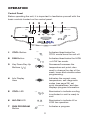
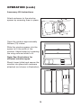
OPERATION
Control Panel
Before operating the unit, it is important to familiarize yourself with the
basic controls located on the control panel.
1 5
3
4
3
COOL
2
7
RUN PROGRAM
START
FAN
HI
STOP
CLOCK TANK FULL
SET PROGRAM
LOW
TIMER
DAY HOUR MIN
Office Pro 10
6
1
COOL Button
Activates/deactivates the
COOL mode/turns the unit off.
2
FAN Button
3
Key Down/Key Up
Buttons ( / )
Decreases/Increases the
temperature set point; also
used to change the day of the
week, hours and minutes when
programming.
4
Info Display
Area
Indicates the current room
temperature, self-diagnostic
codes (see page 26), set
point temperatures, and also
displays program information.
5
COOL LED
6
HI/LOW LED
COOL
Activates/deactivates the HIGH
or LOW fan mode.
FAN
HI
Illuminates to indicate cooling
is activated or unit is ready to
cool.
COOL
HI
7
RUN PROGRAM
Button
LOW
Illuminates to indicate HI or
LOW fan operation.
LOW
Activates a program.
RUN PROGRAM
8
OPERATION (cont.)
Control Panel (Cont.)
12
13 9
COOL
14
RUN PROGRAM
START
FAN
HI
STOP
CLOCK TANK FULL
SET PROGRAM
LOW
TIMER
DAY HOUR MIN
10
11
Office Pro 10
8
8
9
SET PROGRAM
Button
TANK FULL LED
SET PROGRAM
Allows the user to program the
unit or check the current
program.
TANK FULL
Illuminates to indicate the tank
is full.
10 TIMER Button
11 DAY/HOUR/MIN
LED
Allows the user to set the clock
and program the start time and
end time of operation.
TIMER
Illuminates to indicate the day,
hour, and minutes for
programming functions.
DAY HOUR MIN
12 START/STOP LED
START
13 CLOCK LED
14 RUN PROGRAM
LED
Illuminates to indicate the start
and stop operation during
program mode.
STOP
Illuminates to indicate clock
programming sequence during
program mode.
CLOCK
RUN PROGRAM
9
Illuminates to indicate a
program is running. No
illumination indicates unit is in
manual mode.
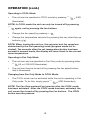
OPERATION (cont.)
Operating in COOL Mode
•
The unit can be operated in COOL mode by pressing
COOL
(LED
illuminates).
NOTE: In COOL mode the unit can only be turned off by pressing
COOL
again, not by pressing the fan buttons.
•
Change the fan speed by pressing
•
Change the temperature set point by pressing the key down/key up
buttons ( / ).
FAN
.
NOTE: When turning the unit on, the set point and fan speed are
determined by the last operating mode (program mode not included). Ten seconds after the set temperature button has been
pressed in manual mode, the display will revert back to the current
room temperature.
Operating in Fan Only Mode
•
The unit can also be operated in Fan Only mode by pressing either
FAN
•
(HI or LOW LED illuminates).
The unit can then be turned off by pressing the fan speed button
that is illuminated.
Changing from Fan Only Mode to COOL Mode
•
The COOL mode can be activated while the unit is operating in Fan
Only mode. To do this, simply press
COOL
(LED illuminates).
NOTE: The Fan Only mode will not operate after the COOL mode
has been activated. After the COOL mode has been activated, the
unit cannot be turned off by pressing the fan buttons. The COOL
button must be pressed.
10
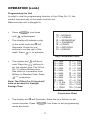
OPERATION (cont.)
Programming the Unit
In order to use the programming function of the Office Pro 10, the
current time and day of the week must be set.
Make sure the unit is plugged in.
•
Press
until
•
four times
SET PROGRAM
CLOCK
The display will indicate a day
of the week code and
DAY
will
illuminate. Press the /
buttons to set the day of the
week. Press
TIMER
=
=
=
=
=
=
=
MO
TU
WE
TH
FR
SA
SU
is illuminated.
MONDAY
TUESDAY
WEDNESDAY
THURSDAY
FRIDAY
SATURDAY
SUNDAY
to advance.
Day Conversion Chart
•
The display and
HOUR
will illumi-
nate. Press the / buttons to
set the current hour. The Office
Pro 10 utilizes Military time.
See chart for conversion from
Military to Standard time. Press
TIMER
to advance.
Note: The Office Pro 10 clock will
have to be reset for Daylight
Savings Time.
01 =
02 =
03 =
04 =
05 =
06 =
07 =
08 =
09 =
10 =
11 =
12 =
1AM
2AM
3AM
4AM
5AM
6AM
7AM
8AM
9AM
10 AM
11AM
12PM
13 =
14 =
15 =
16 =
17 =
18 =
19 =
20 =
21 =
22 =
23 =
00 =
1 PM
2 PM
3 PM
4 PM
5 PM
6 PM
7 PM
8 PM
9 PM
10 PM
11 PM
12 AM
Military to Standard
Conversion Chart
•
The display and
MIN
will illuminate. Press the
current minutes. Press
SET PROGRAM
mode and finish.
11
/
buttons to set
four times to exit programming
OPERATION (cont.)
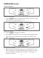
To Set a Program
COOL
P1
START
FAN
HI
STOP
CLOCK TANK FULL
SET PROGRAM
LOW
RUN PROGRAM
TIMER
DAY HOUR MIN
Office Pro 10
Display shows Program 1
1. Press
and P1 will show in the display. There are 7 avail-
SET PROGRAM
able options for programming (P1 - P7).
2. Press / to choose which program to edit. (P1 - P7)
COOL
MO
START
FAN
HI
STOP
CLOCK TANK FULL
SET PROGRAM
LOW
RUN PROGRAM
TIMER
DAY HOUR MIN
Office Pro 10
Display shows Monday
3. Press
until
SET PROGRAM
START
is illuminated.
4. The display will indicate a day of the week code and
nate. Press the
TIMER
DAY
will illumi-
buttons to set the day of the week. Press
/
to advance.
COOL
14
START
FAN
HI
LOW
STOP
RUN PROGRAM
CLOCK TANK FULL
SET PROGRAM
TIMER
DAY HOUR MIN
Office Pro 10
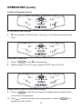
Hour start time is 2:00 P.M.
5.
and display will illuminate. Use / to set desired hour start
time. The Office Pro 10 utilizes Military time. See chart for converHOUR
sion from Military to Standard time on page 11. Press
advance to minutes.
12
TIMER
to
OPERATION (cont.)
To Set a Program (Cont.)
COOL
RUN PROGRAM
30
START
FAN
HI
STOP
CLOCK TANK FULL
TIMER
SET PROGRAM
LOW
DAY HOUR MIN
Office Pro 10
P1 start time is now 2:30 P.M.
6.
and display will illuminate. Use
time.
MIN
/
to set desired minute start
COOL
30
START
FAN
HI
STOP
CLOCK TANK FULL
SET PROGRAM
LOW
RUN PROGRAM
TIMER
DAY HOUR MIN
Office Pro 10
STOP LED is illuminated
7. Press
until
SET PROGRAM
STOP
is illuminated.
8. Repeat steps 4,5 & 6 to set program STOP day and time.
COOL
75
START
FAN
HI
LOW
STOP
RUN PROGRAM
CLOCK TANK FULL
SET PROGRAM
TIMER
DAY HOUR MIN
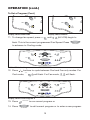
Office Pro 10
Display shows current set temperature flashing
9. Press
SET PROGRAM
until the information display area is flashing the
current set temperature.
10. Use
/ to set a new set point temperature. Press
advance to fan mode.
13
SET PROGRAM
to
OPERATION (cont.)
To Set a Program (Cont.)
COOL
COOL
STA
FAN
HI
STA
FAN
LOW
HI
Display shows FAN LOW
LOW
Display shows FAN HI
11. To change fan speed, press
until
FAN
HI
LOW
(HI/LOW) begin to
flash. This is the current programmed Fan Speed. Press
SET PROGRAM
to advance to Cooling mode.
COOL
RUN PROGRAM
75
START
FAN
HI
STOP
CLOCK TANK FULL
SET PROGRAM
LOW
TIMER
DAY HOUR MIN
Office Pro 10
COOL LED is flashing
12. Press
/
buttons to cycle between Cool and Fan only modes. For
Cool mode,
COOL
will flash. For Fan mode,
COOL
START
HI
LOW
STOP
CLOCK TANK FULL
SET PROGRAM
LOW
will flash.
RUN PROGRAM
P2
FAN
HI
TIMER
DAY HOUR MIN
Office Pro 10
Display shows new Program 2
13. Press
14. Press
RUN PROGRAM
SET PROGRAM
to run current program or
to edit current program or to enter a new program.
14
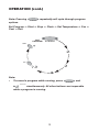
OPERATION (cont.)
Note: Pressing
SET PROGRAM
repeatedly will cycle through program
options.
Set Program Start Stop Clock Set Temperature Fan Cool Exit
EXIT
PROGRAM
SET PROGRAM
COOL
START
FAN
STOP
HI
LOW
CLOCK
Note:
•
To cancel a program while running, press
RUN PROGRAM
SET PROGRAM
and
simultaneously. All other buttons are inoperable
while a program is running.
15
OPERATION (cont.)
Operating Modes
The Office Pro 10 operates in two modes, Fan Only and COOL. When in
Fan Only mode, the unit circulates the surrounding air. When in COOL
mode, the compressor is operational and cool air is circulated.
•
COOL Mode
The unit will operate in Fan Only mode for approximately 120
seconds before the compressor engages. (Time delay setting is
120 ± 15 seconds.)
•
Temperature Control
The room temperature thermistor allows the unit to switch automatically between COOL and Fan Only modes. This is dependent
upon inlet air temperature versus set point temperature.
•
Fan Mode Control DIP Switch
The Fan Mode Control DIP Switch determines whether the FAN will
continue to operate or stop when the compressor cycles off. (Set
point temperature equals inlet air or room temperature.) The unit
has been preset at the factory for continuous fan operation.
•
Temperature Scale Display DIP Switch
The Temperature Scale Display DIP Switch changes the
temperature(s) that are displayed to either °C or °F. The unit has
been preset from the factory to display the temperature(s) in °F.
NOTE: If you wish to change the fan mode operation
(COOLOPERATE to COOLSTOP), and/or the Temperature Scale
Display (°F to °C), contact your MovinCool reseller.
16
OPERATION (cont.)
Emptying the Drain Tank
During COOL mode, condensate will accumulate in the drain tank.
When the drain tank becomes full,
off automatically.
TANK FULL
will flash and the unit will shut
NOTE: If you want to empty the drain tank, while the unit is in
operation, press
COOL
to turn the unit off. If a program is run-
ning, you must first press
RUN PROGRAM
and
SET PROGRAM
simultaneously.
Remove the drain tank panel.
Pull the drain tank from the unit.
Empty the drain tank into a sink.
After it has been emptied, return the
drain tank to the unit.
Reinstall the drain tank panel.
If the
RUN PROGRAM
LED is flashing, press
RUN PROGRAM
the program. If the
RUN PROGRAM
to continue running
LED is illuminated continuously, no
further steps are necessary. If no program exists or the program was
deactivated, press
NOTE:
COOL
to restart the unit.
Do not fill the drain tank with water.
17
OPERATION (cont.)
Installing the Condenser Plenum and Reducer
•
•
•
Align the three notches at the
base of the unit with the three
tabs of the condenser plenum.
Fit all three into place and tilt
condenser plenum up toward
the unit.
LIP
Use the three longer screws
provided and screw the
condenser plenum into place,
turning clockwise to tighten.
Tighten to 1.6 lbs•in torque or
until secure.
EXHAUST AIR
DISCHARGE
FLANGE
Align the reducers’ four (4)
screw holes to the four (4)
screw holes of the exhaust air
discharge flange. Fasten the
screws into place with a
Phillips head screw driver,
turning clockwise to tighten.
Tighten until secure.
REDUCER
CONDENSER
AIR PLENUM
18
OPERATION (cont.)
Accessory Kit
The window kit consists of the following:
REDUCERS (3)
* DUCT CONNECTOR (4)
* (ø6") 5 FT FLEXIBLE DUCT
* (ø6") 5 FT FLEXIBLE DUCT
CONDENSER AIR PLENUM
WING NUTS
COVER PLATE
SLIDER
WINDOW SPACER
SCREWS (13)
* Note: Flexible duct & duct connectors will come preassembled
from factory.
19
OPERATION (cont.)
Accessory Kit Instructions
Attach reducers to the window
spacer by screwing them in place.
Open the window approximately
thirteen (13) inches.
Slide the window spacer into the
space to fit the width of the
window. Adjust slider by loosening
the wing nuts and slide to fit.
Note: See illustrations for
different window types.
Slowly lower (slide) and secure the
window into place with reducers
attached (not shown in illustration).
20
OPERATION (cont.)
Accessory Kit Instructions (Cont.)
Attach duct and duct connector to
the reducer by aligning the
catches with the knobs and turn
counterclockwise to lock in place.
Note: Turn duct connector
clockwise to remove from duct.
Connect the other end of the duct
assembly to the unit by aligning
the catch and knobs and turn
counterclockwise.
Warning: Do not install this
accessory kit on any window
facing outdoors. Rain penetrating through the ducts may cause
slippery floors or electrical
shock. Strong winds may blow
this accessory kit away and
cause injury. This accessory kit
does not prevent unauthorized
entry into the building. Small
pests may enter into the ducts.
21
OPERATION (cont.)
Remote Control (Optional)
5
Office Pro
75
SET RUN
PROGRAM
1
8
7
DAY
HR
MIN
˚F ˚C
START
STOP
CLOCK
TEMP
COOL
SET
4
FAN
TIMER
RUN
PROGRAM
1
COOL Button
2
FAN Button
3
Set Temperature
Buttons ( / )
4
5
Fan Display
Cool On/Off
Display
RUN Button
TIMER Button
6
7
8
9
SET Button
SET PROGRAM
Display Area
10 Info Display Area
11 Clock Display
3
2
6
11
75
SET RUN
PROGRAM
DAY
HR
MIN
˚F ˚C
START
STOP
CLOCK
TEMP
10
9
NOTE: If LO appears in the info
display area, the lowest set point
temperature has been entered. If HI
appears in the info display area, the
highest set point temperature has
been entered.
Activates/deactivates the COOL mode/
turns the unit off.
Activates/deactivates the HIGH or LOW
fan mode. Turns the unit off (Fan only mode)
Increases/decreases the temperature
set point; also used to change the day of the
week, hours and minutes when programming.
Indicates the high, low or fan off modes.
Displays a cool mode symbol when unit is on
or off.
Runs the current program.
Used to set the day and time in hours and
minutes.
Used to set the program entry.
Used to display the set programming for set,
run, start, stop, clock and temperature
functions.
Displays the set point temperature; also used
during the programming mode for display of
days, hours and minutes.
Displays a clock during the programming
mode. To indicate clock is being set.
Note: Press SET PROGRAM and RUN simultaneously to exit SET
PROGRAM and RUN program
22
OPERATION (cont.)
Drain Pump Kit (Optional)
A drain pump kit (CPK-7) is available to allow continuous operation and
to eliminate the need for a drain tank.
•
When the water collects to level
(A) in the pump reservoir, the drain
pump begins to operate and
discharges the water.
A
B
NOTE: The compressor will not operate while the drain pump is
discharging water. The info display area will show AU code while
the pump is discharging the water. When the pump has discharged
the water from the reservoir the AU code will no longer be displayed.
•
When the water level drops below level (B), the drain pump stops,
and the compressor will restart.
NOTE: If the Fan Mode Control DIP Switch (see pg. 16) is set to the
STOP position, the entire unit (including fan operation) will turn off
when the drain pump is discharging water.
NOTE: Before a drain pump can be installed, a pump attachment
plate must be attached to the base of the pump. This pump plate
must then be secured to the base of the unit. Do not install the
condensate pump without the pump plate.
REMOVABLE PANEL
DRAIN PUMP
DRAIN PUMP
RESERVOIR
DISCHARGE HOSE
23
DAILY INSPECTION & MAINTENANCE
Emptying the Drain Tank
To empty the drain tank, refer to the instructions on page 17.
Cleaning the Air Filters
Clean the air filters once a week. If the unit is used in a dusty environment, more frequent cleaning may be required.
A dirty air filter reduces air output resulting in a decrease of the cooling
capacity.
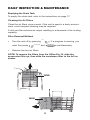
Filter Removal Method
•
Turn the unit off by pressing
must first press
•
RUN PROGRAM
COOL
. If a program is running, you
and
SET PROGRAM
simultaneously.
Remove the two air filters.
NOTE: To remove the filters from the Office Pro 10, slide the
evaporator filter up, then slide the condenser filter to the left as
shown.
FILTER
FILTER
24
DAILY INSPECTION & MAINTENANCE (cont.)
Filter Cleaning Method
•
Remove dust from the element
with a vacuum cleaner, or rinse in
cold or lukewarm water. If the
element is extremely dirty, wash
with a neutral detergent.
•
After the element has been
cleaned, rinse with clean running
water, allow to dry, then reinstall.
In-Season/Off-Season Inspection & Maintenance
■
In-Season
•
Check the prongs and surface of the power cord plug for dust
and/or dirt. If dust and/or dirt are present, wipe off with a clean,
dry cloth.
• Check the power cord, plug and prongs for damage or excess
play. If any damage or excess play is found, contact your
MovinCool reseller for repair.
• Check the air filters and drain tank.
• Clean the outside of the unit with a damp cloth or mild nonabrasive cleaner.
■
Off-Season
• Operate the unit in Fan Only mode for 8 hours.
Note: Operation is necessary to dry out the inside of the unit.
• Disconnect the power cord from the AC outlet.
• Check the prongs and surface of the power cord plug for dust
and/or dirt. If dust and/or dirt are present, wipe off with a clean,
dry cloth.
• Check the power cord, plug and prongs for damage or excess
play. If any damage or excess play is found, contact your
MovinCool reseller for repair.
• Clean the air filters.
• Empty all water from the drain tank.
25
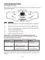
TROUBLESHOOTING
Self-Diagnostic Codes
Self-Diagnostic Codes will be displayed on the Control Board under the
following conditions:
INFO DISPLAY AREA
COOL
RUN PROGRAM
START
FAN
HI
LOW
STOP
CLOCK TANK FULL
SET PROGRAM
TIMER
DAY HOUR MIN
Office Pro 10
Code
Condition
DF
When the evaporator thermistor disengages the compressor.
FL
When the drain tank switch shuts off the unit ( TANK FULL flashes).
AU
When unit disengages the compressor while the condensate
pump is discharging water.
LO
Lowest temperature set point.
HI
Highest temperature set point.
Note: When a self-diagnostic code is displayed the room
temperature will not be displayed. If HP is displayed, call your
MovinCool Reseller/Distributor.
Check the following points before calling a qualified technician.
SYMPTOM
POSSIBLE CAUSE
REMEDY
Unit does not operate
•
•
Reset breaker
Empty the drain tank
Ground fault breaker tripped
Drain tank is full
( TANK FULL will be flashing)
Insufficient cooling
•
•
•
Dirty/blocked air filters
Air inlet/outlet blocked
Improper temperature setting
Clean air filters
Clear air inlet/outlet
Set to desired position
If symptoms persist after the above actions have been taken, turn the
unit off, disconnect the power cord plug and contact your MovinCool
reseller.
26
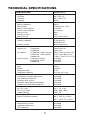
TECHNICAL SPECIFICATIONS
ITEM/FEATURES
Office Pro 10
Rating Conditions
dry bulb
wet bulb
humidity
95º F (35º C)
83º F (28.2º C)
(60%)
Specifications
power frequency
line voltage
power consumption
current consumption
power factor
starting current
power wiring
60Hz
single phase 115 V
1.25 KW
11.5 Amps
95%
40A
14 (3-core) AWG
Cooling Unit
cooling capability
2,440 Kcal/hr
9,600 BTU/hr
direct expansion
cooling system
Blower
type of fan:
air volume:
motor output:
Evaporator
Condenser
Evaporator (High speed)
Evaporator (Low speed)
Condenser
Evaporator (High)
Evaporator (Low)
Condenser
centrifugal fan
turbo fan
595 ft 3/min (1,006 m3/h)
510 ft 3/min (862 m3/h)
1160 ft 3/min (1,971 m3/h)
0.08 KW
0.05 KW
0.08 KW
Compressor
type
output
refrigerant type
refrigerant capacity
rotary
0.68 Kw
R-22
1.61 lbs (0.71 kg)
Safety Devices
compressor overload protector
anti-freezing thermistor
full drain tank switch
automatic restart (power interruption)
compressor time delay program
included
included
included
included
included
Dimensions & Weight
W x D x H (in)
W x D x H (mm)
weight (lbs/kg)
22" x 14" x 38"
559 x 356 x 965
130 / 59
Operating Conditions
inlet air (relative humidity)
95º F (35º C), ≤ 50%
65º F (18.3º C), ≥ 60%
Control Device
temperature control
programmable timer
two speed fan
included
included
included
27
28
LIMITED WARRANTY
The aforesaid warranty is the only warranty made by DENSO with respect to the
Products and is in lieu of all obligations or liabilities on the part of DENSO for
damages arising out of or in connection with the sale, use or performance of the
Products, including, without limitation, any lost profits or any other consequential,
incidental, special or exemplary damages of any kind. DENSO DISCLAIMS ALL
OTHER WARRANTIES WITH REGARD TO THE PRODUCTS, INCLUDING ALL
IMPLIED WARRANTIES OF MERCHANTABILITY AND FITNESS FOR USE. THERE
ARE NO WARRANTIES WHICH EXTEND BEYOND THE DESCRIPTION CONTAINED HEREIN.
PURCHASE DATE: _____________________________________________________
© 2003 DENSO SALES CALIFORNIA, INC.
All rights reserved. This book may not be reproduced or copied, in
whole or in part, without the written permission of the publisher. DENSO
SALES CALIFORNIA, INC. reserves the right to make changes
without prior notice. MovinCool is a registerd trademark of
DENSO Corporation.
SERIAL NUMBER: _____________________________________________________
HERE
DETACH
This warranty does not cover defects or malfunctions which result from causes
beyond DENSO's control, including, without limitation, (i) unusual physical or
electrical stress; (ii) accident, neglect, abuse, misuse or other abnormal use; (iii)
failure to perform routine maintenance in accordance with DENSO'S recommended
procedures; (iv) normal wear and tear; (v) repairs or attempted repairs by an
unauthorized person; (vi) modifications or alterations to the Products; (vii) use with
supplies or devices not supplied or approved by DENSO; or (viii) improper
servicing. This warranty shall extend only to the original end-user and shall be void
if any labels or other identifying marks permanently affixed to Products when
shipped by DENSO are removed, altered, defaced or obliterated.
DENSO SALES CALIFORNIA, INC. ("DENSO") warrants its MOVINCOOL
Products only to the extent stated in its official written warranties. Unless
otherwise specifically provided in writing by DENSO, DENSO warrants to enduser that the Products shall be free of defects in materials or workmanship and will
function in accordance with DENSO's published specifications under ordinary intended use and service for a period of twelve (12) months after delivery to the enduser; provided, however, in the case of the compressor element of the Products
such warranty shall be for a period of thirty six (36) months after delivery to the
end-user. DENSO shall, at its sole option, repair or replace any defective Product
covered by this warranty. Such remedy shall be end-user's sole remedy with
respect to any particular defect in the Products.
OPERATION MANUAL
OFFICE PRO 10
FIRST-CLASS MAIL PERMIT NO. 8390 LONG BEACH, CA
BUSINESS REPLY MAIL
DENSO SALES CALIFORNIA, INC.
3900 VIA ORO AVENUE
LONG BEACH CA 90810-9969
DENSO SALES CALIFORNIA, INC.
3900 Via Oro Avenue
Long Beach CA 90810-1868
800-264-9573 / 310-834-6352
www.movincool.com
NO POSTAGE
NECESSARY
IF MAILED
IN THE
UNITED STATES
Technical Services Department
DSCA P/N: LA990009-1184
GAC P/N: LA484007-1450
First Issue: March 2003
Printed in the U.S.A.
READ THIS MANUAL CAREFULLY FOR INSTRUCTIONS ON CORRECT
INSTALLATION AND USAGE, AND READ ALL SAFEGUARDS.