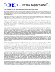
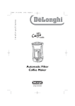
1
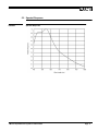
TM-5LC
Super Miniature Cylindrical CCD Camera
Operation Manual
January 31, 2000
69-0051 Rev. A
Notice
The material contained in this manual consists of information that is proprietary to PULNiX America, Inc., and may only
be used by the purchasers of the product. PULNiX America, Inc. makes no warranty for the use of its product and assumes
no responsibility for any errors which may appear or for damages resulting from the use of the information contained
herein. PULNiX America, Inc. reserves the right to make changes without notice.
Warranty
All of our solid state cameras have a full three year warranty. If any such product proves defective during this warranty
period, PULNiX America, Inc. will repair the defective product without charge for parts and labor or will provide a
replacement in exchange for the defective product. This warranty shall not apply to any damage, defect or failure caused
by improper use or inadequate maintenance and use.
Certifications
UL
CE
FCC
This equipment has been tested and found to comply with the limits for a Class A digital device, pursuant to Part 15 of the
FCC Rules. These limits are designed to provide reasonable protection against harmful interference when the equipment
is operated in a commercial environment. This equipment generates, uses and can radiate radio frequency energy and, if
not installed and used in accordance with the instruction manual, may cause harmful interference to radio communications. Operation of this equipment in a residential area is likely to cause harmful interference in which case the user will
be required to correct the interference at his own expense.
WARNING
Changes or modifications to this unit not expressly approved by the party responsible
for FCC compliance could void the user’s authority to operate the equipment.
TM-5LC Operation Manual
Printing: February 2000
PULNiX America, Inc.
1330 Orleans Drive
Sunnyvale, CA 94089
Tel: (408) 747-0300
Tel: (800) 445-5444
Fax: (408) 747-0880
E-mail: [email protected]
TABLE OF CONTENTS
1
INTRODUCTION .......................................................................... 1
1.1
1.2
1.3
1.4
2
INSTALLATION ............................................................................ 4
2.1
2.2
3
Modes of Operation ............................................................................. 7
3.1.1 Timing ..................................................................................... 7
TROUBLESHOOTING ................................................................. 8
4.1
4.2
5
Getting Started .................................................................................... 4
2.1.1 Unpacking Instructions ........................................................... 4
2.1.2 Components List..................................................................... 4
2.1.3 Accessories ............................................................................ 4
Camera Setup...................................................................................... 5
2.2.1 Power Cable............................................................................ 5
2.2.2 Power Supply and Power Cable Setup ................................... 5
2.2.3 Attaching the Camera Lens .................................................... 6
2.2.4 Attaching the C/CS-Mount Adapter and Lens......................... 6
2.2.5 Auto-Iris Lens Setup ............................................................... 6
2.2.6 Monitor Display Mode ............................................................. 6
OPERATION................................................................................. 7
3.1
4
Product Description ............................................................................. 1
Features............................................................................................... 1
Functional Options............................................................................... 2
TM-5LC System Configuration ............................................................ 3
Problems and Solutions....................................................................... 8
4.1.1 Symptom: No Video ................................................................ 8
4.1.2 Symptom: Dark Video ............................................................. 8
4.1.3 Symptom: Non-synchronized Video........................................ 8
Information and Support Resources.................................................... 8
APPENDIX ................................................................................... 9
5.1
5.2
Specifications....................................................................................... 9
5.1.1 Product Specifications ............................................................ 9
5.1.2 Physical Dimensions............................................................... 10
Spectral Response .............................................................................. 11
i
TABLE OF CONTENTS
ii
LIST OF FIGURES
FIGURE 1.
TM-5LC System Configuration ...................................................... 3
FIGURE 2.
TM-5LC Timing Chart .................................................................... 7
FIGURE 3.
Physical Dimensions...................................................................... 10
FIGURE 4.
Spectral Response ........................................................................ 11
iii
LIST OF FIGURES
iv
February 4, 2000
TM-5LC Super-Miniature
Cylindrical CCD Camera
Operation Manual
1
INTRODUCTION
1.1 Product Description
The PULNiX TM-5LC is a miniature monochrome shutter camera with automatic electronic exposure
control. Designed for self-contained miniature camera applications, the TM-5LC provides a robust and
low-cost solution for replacing remote-head cameras. The TM-5LC has a built-in automatic shutter
(electronic iris or electronic exposure control) to provide a wide dynamic range. The camera is designed
for custom optics, and various types of lens mounts are available as an option. The TM-5LC is ideal for
OEM applications, covert operation, robot vision, helmet cameras, pipe inspection, underwater
cameras, microscopy, military applications, etc.
1.2 Features
•
Electronic Shutter
The TM-5LC has a built-in automatic shutter control (electronic iris or electronic exposure control)
that varies from 1/60 sec to 1/10,000 sec, to provide a good image in illumination less than 0.5 lux
to full daylight conditions.
•
Miniaturized and Lightweight
PULNiX designs all of its cameras using solid-state technology. This has enabled a high degree of
miniaturization of housing and cables. The TM-5LC is comparable in size to a camera remote head
and does not require an external control module. In addition, the availability of special mini Tamron
lenses makes it possible to produce a compact, lightweight, robust and highly customized camera
for a variety of specialized uses.
•
High Sensitivity
The TM-5LC series is one of the most low-light sensitive 1/4” CCD cameras available today. This
is especially important when using the faster shutter speeds. The CCD detects images into the near
Page 1
INTRODUCTION
infrared. It requires only 1.0 lux of minimum illumination and 0.5 lux minimum illumination at
maximum gain. In general, such a low light camera allows use of a higher lens F-value and
provides greater depth of field and sharper images.
•
High Resistance To Image Burning
Since the CCD is highly resistant to image burning, the camera may be exposed to bright objects
for a long period of time. It must be noted, however, that a “smear” phenomenon may occur when
shooting a very bright object. An infrared cutoff filter is recommended to obtain a clear picture.
•
High Resistance To Magnetic Field and Vibration/Mechanical Shock
Due to its robust design, the CCD imager can withstand strong vibration and shock, and little or no
noise will appear in the picture. Since the TM-5LC camera is not influenced by a magnetic field, it
will produce stable images even when placed next to objects such as electronic furnaces, welding
machines, or NMR scanners.
•
Low Power Consumption
Typical power consumption is only 1.5W. This makes the camera excellent for use with batteryoperated systems.
•
Optics
The TM-5LC camera is designed for custom optics in OEM applications. The TM-5LC cylindrical
enclosure has M14x0.5 threads that are compatible with Tamron lenses. Additionally, a C/CSmount lens can be used with the optional adapter (part number 32-3663).
•
Three-Year Warranty
The CCD solid state image sensor allows the camera to maintain a superior performance level
indefinitely while requiring virtually no maintenance. PULNiX backs all of the TM-Series cameras
with a three-year warranty.
Warning: Opening the camera in any way will void this warranty.
1.3 Functional Options
Page 2
•
AGC Off (On std.)
•
Gamma 0.45 (1.0 std.)
TM-5LC Super-Miniature Cylindrical CCD Camera
INTRODUCTION
1.4 TM-5LC System Configuration
Figure 1 (below) presents a typical system configuration in which a display monitor or a computer with
grabber board is used.
FIGURE 1.
TM-5LC System Configuration
TM-5LC Super-Miniature Cylindrical CCD Camera
Page 3
INSTALLATION
2
INSTALLATION
The following instructions are provided to help you to set up your video camera system quickly and
easily. It is suggested that you read through these instructions prior to unpacking and setting up your
camera system.
2.1 Getting Started
2.1.1 Unpacking Instructions
It is recommended that the original packing cartons for the cameras and lenses be saved in case there is
a need to return or exchange an item.
It is also recommended that any equipment being sent to another location for field installation be benchtested to assure that everything is fully operational as a system.
2.1.2 Components List
Please begin by checking your order against the Components List (below) to assure that you have
received everything as ordered, and that nothing has been overlooked in the packing materials. If any
item is missing, please contact your PULNiX representative immediately.
•
TM-5LC camera
•
TM-5LC data sheet
•
TM-5LC operation manual
2.1.3 Accessories
Following is a list of additional accessories or equipment that may be recommended or required for your
particular application. Please check with your PULNiX representative prior to the installation of your
video system to determine your exact needs.
Page 4
•
C/CS Mount adapter (part number 32-3663)
•
M14X0.5 Tamron lens (model number 13F033 or 13F038)
•
Power Supply
TM-5LC Super-Miniature Cylindrical CCD Camera
INSTALLATION
2.2 Camera Setup
2.2.1 Power Cable
The TM-5LC has a power cable with color-coded flying leads attached to the back of the camera (see
Figure 3 in Appendix). The lead functions are as follows:
Lead Color
Yellow
Gray
White Coax
Black
Function
+12V DC
GND
Video Out
GND
2.2.2 Power Supply and Power Cable Setup
2.2.2 (a)
Power Supplies
PULNiX recommends the following power supplies:
K25-12
110V AC/12V DC
2.1A power supply
P-15-12
220V AC/12V DC
2.1A power supply
K50-12
110V AC/12V DC
4.2A power supply
PD-12
110V AC/12V DC
0.5A power supply
PD-12U
90-220 AC/12V DC
1.2A power supply
2.2.2 (b)
PD-12 Power Supply
When wiring the PD-12 power supply directly, please note the following:
•
The lead ends must be twisted together and tin-soldered for strength and electrical continuity.
•
Shrink tubing or a similar insulator should be used to prevent exposed leads from touching and
shorting.
•
The +12V lead is marked with a red stripe or white lettering; be sure not to reverse the leads.
•
All connections must be properly insulated to prevent shorting.
2.2.2 (c)
“K” Series Power Supplies
The following procedure should be implemented to connect a “K” series power suply to the TM-5LC
camera:
1.
2.
Attach the 110V line cord to the two terminals marked “AC”. Do not plug the cord into a 110V AC
socket until later in the procedure.
Attach the gray and yellow leads of the power cable to the ground and 12V DC terminals, respectively. Be sure to replace the plastic terminal guard on the power supply at this time.
TM-5LC Super-Miniature Cylindrical CCD Camera
Page 5
INSTALLATION
Note:
The “K” series power supplies are designed primarily for OEM users who will be
mounting the power supply inside a protective enclosure. For use in exposed situations,
the PD-12 and PD-12U are recommended.
2.2.3 Attaching the Camera Lens
The TM-5LC camera accepts a specialized miniature 1/4" format size Tamron lens mount. To attach the
Tamron lens to the camera, carefully engage the threads and rotate the lens clockwise until it firmly
seats on the mounting ring. Do not force the lens if it does not seat properly. Please note that some
lenses with extremely long flangebacks may exceed the mounting depth of the camera.
2.2.4 Attaching the C/CS-Mount Adapter and Lens
An optional C/CS-mount adapter (part number 32-3663) can be used with the TM-5LC. Any C/CSmount lens can be used on the TM-5LC with this adapter. In order to determine the position of the lens
and the adapter, the following procedure should be implemented:
1.
2.
3.
4.
5.
Attach the lens to the adapter.
Loosen the set screws on the adapter and slide it over the camera body.
Set the lens focus to infinity and point the camera at a distant object.
Slide the adapter up/down until the image is in focus.
Tighten the three set screws on the adapter.
2.2.5 Auto-Iris Lens Setup
The TM-5LC camera does not come equipped with auto-iris output. It is possible to use an auto-iris lens
with full video input with the TM-5LC. The following procedure should be followed to connect an autoiris lens to the TM-5LC.
1.
Power down the camera before installing the auto-iris lens.
Note:
2.
3.
Make sure that the power is removed from the camera before connecting or disconnecting
the auto-iris lens. There is a small chance that damage could occur to the auto-iris lens by
plugging or unplugging it while the camera is powered up.
Wire the video signal lead on the lens into the terminal 1 V peak to peak video output on the
camera.
Point the camera at a light area and then quickly towards a dark area. If everything is working properly, the iris should adjust for light change.
2.2.6 Monitor Display Mode
For monitoring real time video, connect the video output to an RS-170 video monitor or other device, as
shown in Figure 1.
Page 6
TM-5LC Super-Miniature Cylindrical CCD Camera
OPERATION
3
OPERATION
3.1 Modes of Operation
3.1.1 Timing
FIGURE 2.
TM-5LC Timing Chart
TM-5LC Super-Miniature Cylindrical CCD Camera
Page 7
TROUBLESHOOTING
4
TROUBLESHOOTING
4.1 Problems and Solutions
Following are troubleshooting tips for common problems. In general, problems can easily be solved by
following these instructions. If the following remedies fail to offer a solution to your problems, please
contact a PULNiX representative.
4.1.1 Symptom: No Video
Remedies: Check that the following are properly connected and operational.
•
Power supplies
•
Main power source
•
Lens
4.1.2 Symptom: Dark Video
Remedy: Check that the iris opening on the lens is properly connected and operational.
4.1.3 Symptom: Non-synchronized Video
Remedy: Check that the frame grabber software camera selection is properly connected and operational.
4.2 Information and Support Resources
For further information and support:
Phone:
(408) 747-0300
(800) 445.5444
(800) 3-PULNIX (24-hour message access)
Fax:
(408) 747-0660
E-mail:
[email protected]
Mail:
PULNiX America Inc.
Sales Department
1330 Orleans Drive
Sunnyvale, CA 94089
ATTN: Video Applications
Web Site:
Page 8
www.pulnix.com
TM-5LC Super-Miniature Cylindrical CCD Camera
APPENDIX
5
APPENDIX
5.1 Specifications
5.1.1 Product Specifications
TABLE 1.
TM-5LC Product Specifications Table
Model
TM-5LC
Imager
1/4" Interline transfer CCD
Pixels
510 (H) x 492 (V)
Cell size
7.15µm x5.55µm
Scanning
Sync
TV resolution
S/N Ratio
Min. illumination
Video output
525 lines @ 60Hz, 2:1 interlace
Internal, Hd=15.734 kHz, Vd=59.95 Hz
400 (H) x 350(V)
50dB minimum
0.5 lux (F=1.4) without IR cut filter
RS-170 Analog: 1.0 Vp-p composite video, 75Ω
AGC
ON/OFF (ON standard)
Gamma
0.45 or 1.0 (1.0 standard)
Lens mount
Power requirement
M14X0.5 Tamron, C/CS Mount
12V DC, 120mA
Operating temp.
-10°C to 50°C
Shock
70G, 11 msec
Random Vibration
Size
Weight
Power cable
Auto iris connector
Power supply
Functional options
Accessories
7Grms/10-2000 Hz
20mm dia. x 52.5mm
0.78" dia. x 2.0"
20.5g (without cable or lens)
Flying leads, 24” length
None
K25-12V or PD-12U
None
C/CS-mount adapter (32-3663)
F3.3mm Mini Tamron lens (11-9002)
F3.8mm Mini Tamron lens (11-2023)
TM-5LC Super-Miniature Cylindrical CCD Camera
Page 9
APPENDIX
5.1.2 Physical Dimensions
FIGURE 3.
Page 10
Physical Dimensions
TM-5LC Super-Miniature Cylindrical CCD Camera
APPENDIX
5.2 Spectral Response
FIGURE 4.
Spectral Response
TM-5LC Super-Miniature Cylindrical CCD Camera
Page 11
APPENDIX
Page 12
TM-5LC Super-Miniature Cylindrical CCD Camera
Industrial Products Division
PULNiX America, Inc.
1330 Orleans Drive
Sunnyvale, CA 94089
Tel: 408-747-0300
Tel: 800-445-5444
Fax: 408-747-0660
Email: [email protected]
www.pulnix.com
Rev. A
Printed: 2/00