1
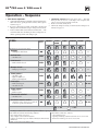
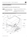
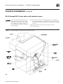
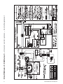
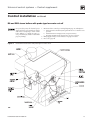
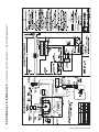
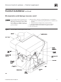
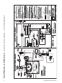
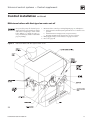
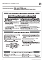
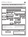
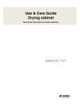
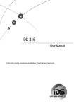
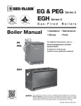
EG & PEG Series 5 EGH Series 5 Gas-Fired Boilers Control supplement – Universal control systems For additional information, refer to . . . (*3(*(*+%RLOHUPDQXDO This supplement must only be used by a qualified heating installer/service technician. Before installing, read all instructions, including this supplement, the boiler manual and any related documents. Perform steps in the order given. Failure to comply could result in severe personal injury, death or substantial property damage. Part Number 550-142-796/1112 EG & PEG SERIES 5sEGH SERIES 5 The following defined terms are used throughout these instructions to bring attention to the presence of hazards of various risk levels or to important information concerning the life of the product. Indicates presence of hazards that will cause severe personal injury, death or substantial property damage. Indicates presence of hazards that can cause severe personal injury, death or substantial property damage. Indicates presence of hazards that will or can cause minor personal injury or property damage. Indicates special instructions on installation, operation or maintenance that are important but not related to personal injury or property damage. Note to the installer Controls must only be installed by a Weil-McLain distributor or other qualified installer/service technician in accordance with this Supplement and all applicable codes and requirements of the authority having jurisdiction. Read this Control Supplement completely before beginning the installation. If the information in this Supplement is not followed exactly, a fire, explosion, carbon monoxide emission or other hazardous conditions can result, causing severe personal injury, death or substantial property damage. This system is used on gas-fired boilers without vent dampers as shipped from the factory. This system is not offered for retrofit. Any attempt to apply the system components to boilers shipped for use with a different control system will not be covered under boiler warranty and can cause severe personal injury, death or substantial property damage. When calling or writing about the boiler, please have the boiler model number from the boiler rating label and the CP number from the boiler jacket. 2 Part Number 550-142-796/1112 Universal control systems — Control supplement Table of contents Hazard definitions and Note to the installer ....................................................................................2 Start-up ...............................................................................................................................................4 Department of Energy – Compliance ...............................................................................................5 Operation – Sequence ................................................................................................................... 5-6 Control installation — EG-30 through EG-75 water boilers without tankless heaters ............ 7-9 Control installation — EG-30 through EG-75 water boilers with tankless heaters...............10-11 Control installation — EG and PEG steam boilers with probe-type low water cutoff..........12-13 Control installation — EG steam boilers with float-type low water cutoff............................ 14-15 Control installation — EGH steam boilers with probe-type low water cut-off ..................... 16-17 Control installation — EGH steam boilers with float-type low water cut-off ....................... 18-19 Damper installation ..........................................................................................................................20 Checkout procedure ........................................................................................................................21 Operating instructions ............................................................................................................... 22-26 Troubleshooting .......................................................................................................................... 27-39 Replacement parts ...........................................................................................................................40 Part Number 550-142-796/1112 3 EG & PEG SERIES 5sEGH SERIES 5 Start-up DO NOT proceed with boiler operation unless boiler and system have been filled with water and all instructions and procedures of previous manual sections have been completed. Failure to do so could result in severe personal injury, death or substantial property damage. Before starting the boiler, do the following: s 2EADTHE-ANUAL#ONTROL3UPPLEMENTANDTHEOperating instruction procedure. s 6ERIFYTHEBOILERANDANDSYSTEMWATERLEVELISCORRECTNOMORETHANGAUGEGLASSORLESS THANvABOVEBOTTOMOFGAUGEGLASSSTEAMBOILERS s 6ERIFYTHEBOILERANDSYSTEMAREfull of waterWATERBOILERS s 6ERIFYTHEStart-up preparation in Boiler manual have been completed. EG & PEG water boilers Adjust boiler control settings BOILER OPERATING TEMPERATURE With power turned on, control module receives a signal from the temperature sensor and displays boiler temperature. The control knob labeled BOILER TEMP is used to adjust the operating temperature setpoint, turning clockwise to increase temperature setting and counterclockwise to decrease. When the knob is turned to adjust temperature the display will brighten to indicate adjustment mode. After temperature is set to desired value, display will dim after approximately 5 seconds to indicate measurement mode. ADJUST BOILER OPERATING TEMPERATURE TO DESIRED SETPOINT BOILER ECONOMY SETTING To comply with Department of Energy regulations, the control module circulates available hot water before turning on the boiler to attempt to satisfy a call for heat. While attempting to satisfy the heat demand, the control module also monitors the boiler temperature changes via the temperature sensor and determines whether or not the available hot water will satisfy the demand, adjusting the time delay to turn on the boiler until it determines that additional heat will be needed. The knob labeled ECONOMY !$*534PROVIDESANADJUSTMENTBETWEENMAXIMIZE-!8AND MINIMIZE-).THEDELAY4HEMAXIMUM-!8ADJUSTMENT position should be used to maximize energy savings. Turning the knob counterclockwise decreases the delay time and should only be used in the event that the heated space becomes uncomfortable. 4 ADJUST ECONOMY TO DESIRED POSITION (MAX IS THE PREFERRED SETTING) IMPORTANT )NACCORDANCEWITH3ECTIONFOFTHE%NERGY0OLICY and Conservation Act, this boiler is equipped with a feature that saves energy by reducing the boiler water temperature as the heating load decreases. This feature is equipped with an override which is provided primarily to permit the use of an external energy management system that serves the same function. 4()3/6%22)$%-534./4"%53%$5.,%33!4,%!34 ONE OF THE FOLLOWING CONDITIONS IS TRUE: s An external energy management system is installed that reduces the boiler water temperature as the heating load decreases. s This boiler is part of a modular or multiple boiler system having a total input of 300,000 BTU/hr or greater. s This boiler is equipped with a tankless coil. Part Number 550-142-796/1112 Universal control systems — Control supplement Department of Energy – Compliance This boiler is equipped with a control system that automatically adjusts a time delay period to turn on the boiler during a call for heat. This is accomplished by circulating available hot water in the system while measuring water boiler water temperature changes. The control calculates a suitable delay based on temperature measurements and turns the boiler on only after it determines that the demand for heat cannot be satisfied with the available hot water, Due to the wide variety of controls used in boiler installations, this control is also equipped with an adjustment FORTHECALCULATEDTIMEDELAYPERIOD%#/./-9!$*534)NTHE-).POSITIONTHETIMEDELAYISZEROANDTHE IMPORTANT notice below must be observed: IMPORTANT )NACCORDANCEWITH3ECTIONFOFTHE%NERGY0OLICYAND#ONSERVATION!CTTHISBOILERISEQUIPPEDWITH a feature that saves energy by reducing the boiler water temperature as the heating load decreases. This feature is equipped with an override which is provided primarily to permit the use of an external energy management system that serves the same function. 4()3/6%22)$%-534./4"%53%$5.,%33!4,%!34/.%/&4(%&/,,/7).'#/.$)4)/.3)3425% s An external energy management system is installed that reduces the boiler water temperature as the heating load decreases. s This boiler is part of a modular or multiple boiler system having a total input of 300,000 BTU/hr or greater. s This boiler is equipped with a tankless coil. Operation – Sequence Follow all procedures given in this manual and operating instructions when operating the boiler. Failure to do so could result in severe personal injury, death or substantial property damage. Standby: With no call for heat, the vent damper and circulator are de-energized. No gas flows to pilot or main gas valve. 2. Call for heat THERMOSTATCIRCUITCLOSES For water boilers , while attempting to satisfy the heat demand, the 3. Pilot ignition: Control module sparks the pilot and opens pilot valve in main gas valve. a. If pilot does light and control module senses flame current, spark generator is turned off and main valve opens. b. Natural Gas - )FPILOTDOESNOTLIGHTWITHINSECONDS pilot valve is closed and spark generator is turned off. Control module waits 5 minutes, then attempts to ignite pilot again. This cycle will continue indefinitely if pilot ignition control does not sense pilot flame. control module monitors the boiler temperature changes via the temperature sensors and determines whether or not the available hot water will satisfy the demand, only running the circulator. If ADDITIONALHEATISNEEDEDTHESEQUENCECONTINUES7HEN$(7IF USEDCALLSFORHEATSEQUENCEABOVEISBYPASSED A 6ENTDAMPERANDCIRCULATORENERGIZEDIFPILOTSTATUSACCEPTABLE6ENTDAMPERDRIVESOPEN7HENVENTDAMPERENDSWITCH makes circuit, ignition control begins pilot ignition attempt. b. Ignition control checks for false flame signal: If ignition control senses pilot signal when no pilot gas should be present, control will lockout, requiring reset procedure as given in Figure 1 Part Number 550-142-796/1112 5 EG & PEG SERIES 5sEGH SERIES 5 Operation – Sequence 4. Main burner operation: a. Control module monitors pilot flame current. If signal is lost, main valve closes, spark generator activates and sequence returns to step 4. b. If power is interrupted, control system shuts off pilot and MAINGASVALVESANDRESTARTSATSTEPWHENPOWERISRESTORED c. In the event the limit control shuts down the boiler — The control module closes the main gas valve, but keeps the circulator operating and the vent damper open. 5. Thermostat satisfied THERMOSTAT CIRCUIT OPENS 0ILOT AND MAIN GAS VALVES ARE CLOSED 6ENT DAMPER IS DEENERGIZED AND cycles to closed position. Circulator is shut off. 6. Boiler is now in the standby mode. 7. Thermostat anticipator setting: Set thermostat heat anticipator as instructed on PAGE Figure 1 Ignition control module sequence of operation — status light indications — EG Water Only STEPS Call for Heat? POWER TSTAT CIRC LIMIT DAMPER FLAME Timing (After Step 8, the cycle goes back to Step 1) 1. Standby s Waiting for call for heat NO — 2. Call for heat s Circulator on YES — 3. Limit circuit s Limit controls closed YES — 4. Damper circuit s Damper proven open YES — 5. Flame proven * s Gas valve open s Ignitor remains on s Boiler producing heat YES 15 sec 6. Limit cycle s Limit circuit open s Gas valve closed YES 30 sec 7. Flame outage * s Flame out s Boiler recycles YES — 8. Thermostat satisfied s Circulator off NO 15 sec 9. Circulator exercise routine s Circulator turns on for 30 seconds if boiler not operated for 30 days NO 30 sec = ON = OFF * See Page 5, Items 3b for controls response to failure to prove pilot flame. Control will lockout under the following conditions: Control will reset after these lockouts : s,INEVOLTAGEPOLARITYISREVERSED sHOURWAITINGPERIOD s3TRAYVOLTAGEISSENSEDONTHERMOSTATLINE s Opening and closing of thermostat circuit for 2 to 20 seconds s Damper end switch not proven within 5 minutes from thermostat s2EMOVALOF6!#POWERFORTOSECONDS call for heat sFlame is sensed when it shouldn’t be there 6 Part Number 550-142-796/1112 Universal control systems — Control supplement Control installation EG-30 through EG-75 water boilers without tankless heaters Part Number 550-142-796/1112 Schematic wiring diagram 7 EG & PEG SERIES 5sEGH SERIES 5 Control installation EG-30 through EG-75 water boilers without tankless heaters Ladder wiring diagram 8 Part Number 550-142-796/1112 Universal control systems — Control supplement Control installation EG-30 through EG-75 water boilers without tankless heaters For your safety, turn off electrical power supply and turn off external gas supply valve before attempting to work on the boiler. Failure to comply can cause severe personal injury, death or substantial property damage. Figure 2 -OUNTANDWIRECONTROLSPERWIRINGDIAGRAMPAGEAND&IGURE A !TTACHJUNCTIONBOXINSIDELEFTJACKETPANELWITHX vMACHINESCREWS provided. b. Install transformer with plug-in relay receptacle and relay. C /PERATINGANDLIMITCIRCUITWIRINGMUSTBEGAUGEORHEAVIER "RINGSUPPLYWIRINGTOBOILER-USTBEGAUGEORHEAVIER 3. Proceed to page 20. EG-30 through EG-75 water boilers without tankless heaters Part Number 550-142-796/1112 9 Part Number 550-142-796/1112 %'0%'3ERIESs%'(3ERIES — Universal control systems — Control Supplement Universal control systems — Control supplement Control installation continued EG-30 through EG-75 water boilers with tankless heaters For your safety, turn off electrical power supply and turn off external gas supply valve before attempting to work on the boiler. Failure to comply can cause severe personal injury, death or substantial property damage. Figure 3 -OUNTANDWIRECONTROLSPERWIRINGDIAGRAMPAGEAND&IGURE a. Install combination limit control and relay in tapping. See Boiler Manual CONTROLTAPPINGTABLE/PERATINGANDLIMITCIRCUITWIRINGMUSTBEGAUGE or heavier. "RINGSUPPLYWIRINGTOBOILER-USTBEGAUGEORHEAVIER 3. Proceed to page 20. EG-30 through EG-75 water boilers with tankless heaters Part Number 550-142-796/1112 Part Number 550-142-796/1112 %'0%'3ERIESs%'(3ERIES — Universal control systems — Control Supplement Universal control systems — Control supplement Control installation continued EG and PEG steam boilers with probe-type low water cut-off For your safety, turn off electrical power supply and turn off external gas supply valve before attempting to work on the boiler. Failure to comply can cause severe personal injury, death or substantial property damage. Figure 4 -OUNTANDWIRECONTROLSPERWIRINGDIAGRAMPAGEAND&IGURE A !TTACHJUNCTIONBOXINSIDELEFTJACKETPANELWITHX vMACHINESCREWS provided. b. Install transformer with plug-in relay receptacle and relay. C /PERATINGANDLIMITCIRCUITWIRINGMUSTBEGAUGEORHEAVIER "RINGSUPPLYWIRINGTOBOILER-USTBEGAUGEORHEAVIER 3. Proceed to page 20. EG and PEG steam boilers with probe-type low water cut-off Part Number 550-142-796/1112 Part Number 550-142-796/1112 %'0%'3ERIESs%'(3ERIES — Universal control systems — Control Supplement Universal control systems — Control supplement Control installation continued EG steam boilers with float-type low water cut-off For your safety, turn off electrical power supply and turn off external gas supply valve before attempting to work on the boiler. Failure to comply can cause severe personal injury, death or substantial property damage. Figure 5 -OUNTANDWIRECONTROLSPERWIRINGDIAGRAMPAGE and Figure 5. A !TTACHJUNCTIONBOXINSIDELEFTJACKETPANELWITHX vMACHINESCREWS provided. b. Install transformer with plug-in relay receptacle and relay. C /PERATINGANDLIMITCIRCUITWIRINGMUSTBEGAUGEORHEAVIER "RINGSUPPLYWIRINGTOBOILER-USTBEGAUGEORHEAVIER 3. Proceed to page 20. EG steam boilers with float-type low water cut-off Part Number 550-142-796/1112 Part Number 550-142-796/1112 %'0%'3ERIESs%'(3ERIES — Universal control systems — Control Supplement Universal control systems — Control supplement Control installation continued EGH steam boilers with probe-type low water cut-off For your safety, turn off electrical power supply and turn off external gas supply valve before attempting to work on the boiler. Failure to comply can cause severe personal injury, death or substantial property damage. Figure 8 -OUNTANDWIRECONTROLSPERWIRINGDIAGRAMPAGE, and Figure 8. A !TTACHJUNCTIONBOXINSIDELEFTJACKETPANELWITHX vMACHINESCREWS provided. b. Install transformer with plug-in relay receptacle and relay. C /PERATINGANDLIMITCIRCUITWIRINGMUSTBEGAUGEORHEAVIER "RINGSUPPLYWIRINGTOBOILER-USTBEGAUGEORHEAVIER 3. Proceed to page 20. EGH steam boilers with probe-type low water cut-off Part Number 550-142-796/1112 Part Number 550-142-796/1112 %'0%'3ERIESs%'(3ERIES — Universal control systems — Control Supplement Universal control systems — Control supplement Control installation continued EGH steam boilers with float-type low water cut-off For your safety, turn off electrical power supply and turn off external gas supply valve before attempting to work on the boiler. Failure to comply can cause severe personal injury, death or substantial property damage. Figure 9 -OUNTANDWIRECONTROLSPERWIRINGDIAGRAMPAGE23, and Figure 9. A !TTACHJUNCTIONBOXINSIDELEFTJACKETPANELWITHX vMACHINESCREWS provided. b. Install transformer with plug-in relay receptacle and relay. C /PERATINGANDLIMITCIRCUITWIRINGMUSTBEGAUGEORHEAVIER "RINGSUPPLYWIRINGTOBOILER-USTBEGAUGEORHEAVIER 3. Proceed to page 20. EGH steam boilers with float-type low water cut-off Part Number 550-142-796/1112 EG & PEG SERIES 5sEGH SERIES 5 Damper installation If not installing a vent damper, proceed to page . Figure 10 Vent damper assemblies Once damper is installed, boiler will not operate without a damper installed. Only dampers listed in the Replacement parts table on page 40 are approved for use on EG-30 through EG-75 Series 5 and PEG-30 through PEG-65 Series 5 using Universal Control Systems. Any other vent damper installed could cause severe personal injury or death. The following boiler models must have damper installed: s %'THROUGH%'NATURALORLIQUEled petroleum (propane) gas. s 0%'THROUGH0%'STEAMNATURALGAS Figure 11 Vent damper harness plug warning label The following boiler models may have damper installed: s %'AND%'(THROUGH%'(NATURALORLIQUEled petroleum (propane) gas. Minimum clearances to combustibles 0ROVIDEAMINIMUMOFvBETWEENTHEVENTDAMPERANDANYCOMBUSTIBLE MATERIAL0ROVIDEAMINIMUMOFvBETWEENJACKETTOPANDCOMBUSTIBLE CEILING FOR %'0%' AND %'( 3EE %' s 0%' s %'( "OILER MANUAL FOR complete clearance requirements. Installation Damper must be installed directly on top of draft hood so that it serves only that boiler. Do not modify draft hood or damper, or make another connection between draft hood and damper or boiler except as noted below. This will void CSA certification and will not be covered by Weil-McLain warranty. Any changes will cause severe personal injury, death, or substantial property damage. 5. Read and apply the harness plug warning label &IGURESOTHATITISVISIBLEAFTERINSTALLATION 6. Plug damper harness receptacle into damper harness plug. )NSTALLPLUGPACKEDINDAMPERCARTONOFvTHROUGHvDAMPERSIN hole in damper blade. 2. Install vent damper horizontally or vertically as shown in vent damper MANUFACTURERSINSTRUCTIONS6ENTDAMPERMUSTBEINSTALLEDSOTHATIT serves only one boiler and so damper blade indicator is visible to the USER3EE&IGURE 3. Screws or rivets used to secure the vent damper to the draft hood must not interfere with rotation of the damper blade. 4. Install damper harness between damper actuator and knockout in jacket top panel. Use strain relief connectors and locknuts to secure both ends of the damper harness. After boiler has operated once, if either end of the harness is disconnected, the system safety shutdown will occur. The boiler will not operate until harness is reconnected. Keep wiring harness clear of all hot surfaces. 20 "YPASSINGJUMPERINGVENTDAMPERWILL cause flue products such as carbon monoxide to escape into the house. This will cause severe personal injury or death. Effikal or Field Controls damper — Damper hold open switch must be in “AuTOMATIC/PERATIONvPOSITIONFORSYSTEMTO operate properly. Part Number 550-142-796/1112 Universal control systems — Control supplement Checkout procedure 3EEPAGESnFORh/PERATINGINSTRUCTIONSv 2. Raise room thermostat to call for heat. Damper actuator will slowly open damper. 3. When damper is fully open, main gas valve will open and main burners will ignite. Damper must be fully open before main burners light. If damper does not fully open, flue products will escape into house, causing severe personal injury or death. 4. Lower thermostat setting. Main burner flames will go out, then damper will close. 2EPEATSTEPSTHROUGHSEVERALTIMESTOVERIFYOPERATION 6. Return thermostat to normal setting. Room thermostat anticipator settings Water without tankless heater — 0.40 amps Water with tankless heater — 0.20 amps Steam — Select based on gas valve and damper. See table below. Boilers with United Technologies Ignition control Gas valve (control load of 0.10 amps is included in the values at right) Without damper (amps) With Effikal damper (amps) With Johnson damper (amps) Honeywell VR8200 0.60 0.70 0.80 Honeywell VR8300 0.80 0.90 1.00 Robertshaw 7200ER 0.50 0.60 0.70 Robertshaw 7000ERHC 0.80 0.90 1.00 White-Rodgers 36E 0.40 0.50 0.60 White-Rodgers 36C 0.70 0.80 0.90 Without damper (amps) With Effikal damper (amps) With Johnson damper (amps) Boilers with Honeywell Ignition control Gas valve (control load of 0.20 amps is included in the values at right) Honeywell VR8200 0.70 0.80 0.90 Honeywell VR8300 0.90 1.00 1.10 Robertshaw 7200ER 0.60 0.70 0.80 Robertshaw 7000ERHC 0.90 1.00 1.10 White-Rodgers 36E 0.50 0.60 0.70 White-Rodgers 36C 0.80 0.90 1.00 Part Number 550-142-796/1112 EG & PEG SERIES 5sEGH Operating instructions – SERIES 5 EG and PEG with Honeywell VR8204/VR8304 gas valve 22 Part Number 550-142-796/1112 Universal control systems — Control supplement Operating instructions – EG/PEG-30 through EG/PEG-50 with White-Rodgers 36E gas valve Part Number 550-142-796/1112 23 EG & PEG SERIES 5sEGH Operating instructions – SERIES 5 EG/PEG-30 through EG/PEG-50 with Robertshaw 7200 gas valve 24 Part Number 550-142-796/1112 Universal control systems — Control supplement Operating instructions – EG/PEG-55, EG/PEG-65, EG-75 with White-Rodgers 36C gas valve Part Number 550-142-796/1112 25 EG & PEG SERIES 5sEGH Operating instructions – SERIES 5 EGH with Robertshaw 7000DERHC gas valve 26 Part Number 550-142-796/1112 Universal control systems — Control supplement Troubleshooting Burner access panel must be in position during boiler operation to prevent momentary flame rollout on ignition of main flame. Severe personal injury or substantial property damage will result. Sensor resistance values Sensor ohms Sensor ohms .EVER JUMPER BYPASS ANY DEVICE EXcept for momentary testing as outlined in Troubleshooting Charts. Substantial property damage and/or severe personal injury could occur. Label all wires prior to disconnection when servicing controls. Wiring errors can cause improper and dangerous operation. Temp (°F) Min Max Temp (°F) 32 34265 37871 120 4517 4992 40 27834 30764 130 3698 4088 50 21630 23907 140 3043 3364 6ERIFYPROPEROPERATIONAFTERSERVICING3EE vent damper manufacturer’s instructions packed with vent damper for additional information. Failure to comply could result in severe personal injury, death or substantial property damage. 60 16944 18727 150 2517 2782 70 13372 14780 160 2091 2311 80 10629 11747 170 1744 1928 90 8504 9399 180 1461 1615 100 6847 7568 190 1229 1359 110 5545 6129 200 1038 1147 Before troubleshooting (AVEAVOLTMETERTHATCANCHECK6!#6!# and a continuity tester. #HECKFOR6!#MINIMUMTOMAXIMUM TOBOILER 3. Make sure thermostat is calling for heat and contacts INCLUDING APPROPRIATE ZONE CONTROLS ARE CLOSED #HECKFOR6!#BETWEENTHERMOSTATWIRENUTSAND ground. Supply temperature sensor The boiler temperature sensor is a resistance-type device. 2. The Table, shows the correct value for the sensor at various temperatures. 3. Use the resistance values at 32°F, 60°F, 70°F and & TO MEASURE THE SENSOR RESISTANCE AT KNOWN TEMPERATURES ICE POINT ROOM TEMPERATURE AND SEALEVELBOILINGPOINT&ORICEPOINTANDBOILING point, insert the sensor in water at that temperature. Use an ohmmeter to read resistance value between thermister # and thermistor common. 3EE&IGUREFORPINLOCATIONS Figure 12 Table Supply temperature sensor resistance values Supply temperature sensor Min Max In event of vent damper failure: Effikal or Field Controls vent damper If troubleshooting chart recommends replacing actuator and actuator is not immediately available, damper blade can be fixed in an open position to allow boiler operation. Manually turning blade can cause actuator damage. Follow these instructions only in case of no heat or damper actuator malfunction. -OVEDAMPERSERVICESWITCHTOHold Damper Open position. Apply call for heat to boiler. Damper blade should then rotate to open position and boiler will fire. )FSTEPDOESNOTOPENDAMPERMANUALLYROTATEDAMPERBLADETOOPEN position using wrench or pliers on flat shaft between damper and actuaTOR"OILERWILLlRE6ERIFYTHATDAMPERSERVICESWITCHISIN(OLD$AMPER /PENPOSITION&IGUREPAGE 3. Do not leave vent damper permanently in this position. Replace actuator immediately. If vent damper is left in open position, boiler will not operate at published efficiencies. Johnson Controls vent damper If troubleshooting chart recommends replacing actuator and actuator is not immediately available, damper blade can be fixed in an open position to allow boiler operation. Follow these instructions only in case of no heat ORDAMPERACTUATORMALFUNCTION3EE&IGUREPAGE 4URNOFFPOWERTOBOILER Failure to turn off power to boiler can result in severe personal injury, death or substantial property damage. 2. Refer to vent damper manufacturer’s instructions for procedure to fix vent damper in open position. 3. Turn on power to boiler. Part Number 550-142-796/1112 27 EG & PEG SERIES 5sEGH SERIES 5 Troubleshooting – (EG water boilers) 4. Using wrench or pliers on flat shaft section, manually rotate damper blade until green light turns on. "OILERWILLlRE&IGURE 5. Do not leave vent damper permanently in this position. Replace actuator immediately. If vent damper is left in open position, boiler will not operate at published efficiencies. Figure 13 Manually opening vent damper Make sure ground wiring is installed per wiring diagram. Good grounding is extremely important for proper operation. Control indicator lights — HARD LOCKOUT Summary (Flashing LED’s) !"#$%&" '( & )! & * INDICATOR LIGHT CONDITION POWER The information on this page and pages 33 through 39 apply only to spark-ignited pilot EG water boilers. These boilers are equipped with an ignition control module that has indicator lights to show control status. Charts 1 through 6, pages 30 through 35, help you identify problems based on indicator light conditions. Figure 14 EG-water Ignition control module + !"#$%3 * + "8 : ; )* + <8 =* + >8 =* + ?8 : ;& * + @8 : ; * 8+ A'BC(CDG";<;* ) &3)";* CDHI+IJ:K + 3 G >* SOFT LOCKOUT Summary (Flashing LED’s) !"#$%&";) 3&""#;'( & ) !&* INDICATOR LIGHT CONDITION 'BC(LMIMMQ%:(% J MIMM* 'BC(LDC( D 3 &&>?MIM * 'BC(L+C + & * CAUTION Summary (Flashing LED’s) INDICATOR LIGHT Control module Solder or water splatter between plugs and circuit board can cause improper operation of control module. Place a shield over the boiler internal controls and components during installation. Failure to comply could result in severe personal injury, death or substantial property damage. 28 CONDITION DC( D& 3 * ::M + &* +C + G * Troubleshooting the control module See &IGUREpage 29, for location of harness plug receptacles and plugs on the control module. Part Number 550-142-796/1112 Universal control systems — Control supplement Troubleshooting – (EG water boilers) Figure 15 continued Control module connections Part Number 550-142-796/1112 29 EG & PEG SERIES 5sEGH SERIES 5 Troubleshooting – (EG water boilers) continued – Spark-ignited pilot – Troubleshooting POWER light status CHART 1 ! (OHFWULFDOVKRFNKD]DUGSB)ʆ78512))32:(5ʆ; &* – + & T);3 )* Is POWER light off? No s Make sure service switch or circuit breaker is on or fuses are good. Yes s Remove 120 VAC IN plug (Figure 15, Item 3, page 29) on control module. s Using voltmeter, check across top and bottom pins of 120 VAC IN plug. Is POWER light . . . Flashing alone? Flashing with another light? On steady (NOT flashing)? Does voltmeter indicate 120 VAC? No TSTAT/CIRC light flashing Chart 3 Damper light flashing Chart 4 Yes Problem is with incoming electricity. Have licensed electrician repair circuit. s Reconnect 120 VAC IN plug. FLAME light flashing Chart 5 Chart 6 For insufficient heat or no heat problem, go to s Remove 120 VAC transformer PRIMARY plug (Figure 15, Item 3, page 29) on control module. s Using voltmeter, check across top and bottom pins of PRIMARY receptacle. Chart 6, page 35, if Power light is on steady, Does voltmeter indicate 120 VAC? with no the light flashing. No Yes s Replace control module. s Usually indicates polarity on incoming 120 VAC power line is wrong. ʆ78512))32:(5ʆ at service switch or breaker, then reverse the HOT and NEUTRAL wires entering the boiler in the J-box. s Restore POWER at service switch or breaker. Is POWER light flashing now? No Yes s Retest. s Reinstall 120 VAC transformer PRIMARY plug. s Remove 24 VAC transformer plug (Figure 15, Item 3, page 29) on control module. s Using voltmeter, check across pins of receptacle. Does voltmeter indicate 24 VAC? No Yes Have system checked by a licensed electrician. Boiler should now operate normally. 30 If problem persists, call your local Weil-McLain sales representative. s Replace transformer. s Replace control module. s Retest. s Retest. Part Number 550-142-796/1112 Universal control systems — Control supplement Troubleshooting – (EG water boilers) CHART 2 continued – Spark-ignited pilot – TSTAT/CIRC & POWER light flashing – Usually indicates 48 VAC on thermostat circuit (stray voltage) – (OHFWULFDOVKRFNKD]DUGSB)ʆ78512))32:(5ʆ; &* – + & T);3 )* s Disconnect the two external wires connected to the boiler thermostat leads. (two black low voltage leads in J-box). s Connect a voltmeter across the two incoming wires. Close each thermostat, zone valve and relay in the external circuit one at a time and check the voltmeter reading across the wires. s If a voltage does occur under any condition, check and correct the external wiring. (This is a common problem when using 3-wire zone valves.) s Once the external thermostat circuit wiring is checked and corrected if necessary, reconnect the external thermostat circuit wires to the boiler thermostat wires and allow the boiler to cycle. s There should NEVER be a voltage reading. Did you find a voltage across the two external thermostat circuit wires? Yes s Leave external boiler thermostat connection wires disconnected from boiler. s Trouble shoot the external thermostat circuit until you find the source of the stray voltage. (Pay close attention to the wiring connections to 3-wire zone valves.) s Correct the problem and repeat voltmeter test above, verifying there is no longer a voltage reading under any condition in the external thermostat circuit. No s If no voltage is found under any condition of the external thermostat circuit, connect the two boiler thermostat connection leads together (or jumper the boiler aquastat T-T terminals). s Turn off power to the boiler for 1 minute. s Turn on power and allow boiler to cycle. Do the TSTAT and POWER lights still flash? No s Boiler should now operate per the normal sequence of operation shown in Figure 1, page 6. Part Number 550-142-796/1112 Yes s Replace control module. s Retest. EG & PEG SERIES 5sEGH SERIES 5 Troubleshooting – (EG water boilers) CHART 3 continued – Spark-ignited pilot – DAMPER light flashing "#$%& ' * +* "#$%& ' * (OHFWULFDOVKRFNKD]DUGSB)ʆ78512))32:(5ʆ; &* – + & T);3 )* s Reset boiler control by turning off power at service switch or turning down thermostat for at least 45 seconds. s Thermostat should call for heat and appropriate zone valves open. The 767$7&,5&and/,0,7and lights should come on. Does Vent Damper operate? No Yes s Wait 45 seconds. Does Vent Damper operate? No Yes s Remove Damper plug (Figure 15, Item 6, page 29) from plug receptacle of control module. s Place voltmeter leads across the top two pins (1 and 4) of the Damper receptacle. s Wait 5 minutes. Is PRESS SWITCH light still flash? Does the voltmeter indicate 24 VAC? No No Yes Yes s Try reseating plug in module receptacle and restart. s Boiler should be in normal operating sequence. s If vent damper still does not work, replace vent damper assembly or actuator. s Observe operation until thermostat is satisfied. Does vent damper actuator indicator show damper is open? s Retest. No Yes Are the TSTAT/CIRC and LIMIT lights on steady? Yes s Replace control module. s Retest. 32 No s Make sure thermostat is calling for heat. If lights still don’t come on, see Chart 6, page 35. s Replace vent damper assembly or actuator. s Retest. s Remove damper wiring plug at damper and firmly reconnect. s Recheck boiler operation. s If problem persists, replace vent damper assembly or actuator. Part Number 550-142-796/1112 Universal control systems — Control supplement Troubleshooting – (EG water boilers) continued – Spark-ignited pilot – FLAME & POWER light flashing CHART 4 * ,! (OHFWULFDOVKRFNKD]DUGSB)ʆ78512))32:(5ʆ; &* – + & T);3 )* Are manual main shutoff valve and gas valve open? No Yes s Leave main manual gas valve closed s Turn off power to boiler at service switch or breaker. s Turn off power to boiler at service switch or breaker. s Wait at least 45 seconds. s Wait at least 45 seconds. s Turn on power to boiler. s Turn on power to boiler. s Restart boiler, following Operating instructions in this manual or on the boiler label. s Restart boiler, following Operating instructions in this manual or on the boiler label. s Look through the pilot inspection port to see if the pilot is burning. Do FLAME and POWER lights still flash? No Is pilot burning? Yes No Yes s Replace control module. s Retest. s Allow boiler to continue cycling. Are FLAME and POWER lights flashing? No ʆ78512))32:(5ʆ to boiler at service switch or breaker. s Open main manual gas valve. s Turn on power to boiler at service switch or breaker. s Restart boiler per operating instructions. s Perform start-up procedures in boiler manual to verify proper operation. s Boiler may now be operating normally. s Perform start-up procedures in boiler manual to verify proper operation. Part Number 550-142-796/1112 Yes s Replace gas valve. s Retest boiler. Are FLAME and POWER lights flashing? No s Replace control module. s Boiler should now operate normally. s Retest. s Original flashing FLAME light caused by gas valve not operating properly. Yes s Replace control module. s Retest. s See normal sequence of operation, Figure 1, page 6. 33 EG & PEG SERIES 5sEGH SERIES 5 Troubleshooting – (EG water boilers) continued – Spark-ignited pilot – FLAME light flashing and POWER light on steady ALSO –– Troubleshooting failure to establish main flame CHART 5 (OHFWULFDOVKRFNKD]DUGSB)ʆ78512))32:(5ʆ; &* – + & T);3 )* Are manual main shutoff valve and gas valve open? No s Is pilot flame visible through inspection ? Yes ʆ78512))32:(5ʆ to boiler at service switch or breaker. s Open main manual shutoff valve and boiler gas valve (per Operating instructions in this manual). Wait at least 45 seconds. s Turn on power at service switch or breaker. Allow boiler to cycle . No Yes s Check the voltage across main gas valve terminals of the gas valve. s Make sure ground wire terminal is securely fastened to control module mounting screw. Is 24 VAC present there? Yes No Does FLAME light flash now? No s Boiler should be in normal operating sequence. Yes s Verify inlet gas pressure at gas valve: s Observe operation until thermostat is satisfied and blower has completed its post-purge cycle. Natural gas – 5.0” w.c. min/14.0” w.c max Propane – 11.0” w.c. min/14.0” w.c max Is gas present at gas valve inlet and within above range? Yes No s Check the voltage across main gas valve terminals of the gas valve. s If the wiring from the control module to gas valve is intact, replace the control module. Is 24 VAC present there? s Retest. No s Verify inlet gas pressure at gas valve: Natural gas – 5.0” w.c. min/14.0” w.c max Propane – 11.0” w.c. min/14.0” w.c max Is gas present at gas valve inlet and within above range? No ʆ78512))32:(5ʆ to boiler at service switch or breaker. s Remove base access panel. s Verify pilot gas line is not kinked, obstructed or damaged and is correctly attached to pilot and gas valve. s Verify pilot ignition electrode, electrode ceramic and spark lead wire from control are in good condition. Spark gap should be approxiamtely 1/8”. s Correct any above problems, replacing pilot if burner or wiring is damaged. s Reinstall base access panel to operate boiler for retest after any changes or corrections. s If none of the above corrects problems, then replace the control module, reinstall base access panel, and retest. 34 s Contact gas supplier to correct pressure or gas supply. ʆ78512))32:(5ʆ to boiler at service switch or breaker. s Remove base access panel. s Verify pilot burner is securely attached to pilot bracket, bracket is securely attached to cross-tie, and there is no corrosion on the the ground path for flame sense. s Verify that pilot flame rod, flame rod ceramic and lead wire from control module to flame rod are in good condition. s Correct any above problems, replacing pilot if burner or wiring is damaged. Yes Yes ʆ78512))32:(5ʆto boiler at service switch or breaker. s Check flame signal – Detach lead from ignition control (Figure 15, Item 8, page 29). s Connect negative lead of MICROAMMETER to control sense terminal (Figure 15, Item 8, page 29). Connect positive lead of MICROAMMETER to sense wire. s DISCONNECT red wire connected to main gas valve terminal of the gas valve. s Turn on power to boiler and allow to cycle. As soon as pilot is burning, the MICROAMMETER should read at least 1.0 microamp. Is flame signal at least 1.0 microamp ? No Yes s If none of the previous steps (including replacing pilot) corrects problem, then replace the control module, reinstall base access panel and retest. s If the wiring from the control module to gas valve is intact, replace the control module and retest. Part Number 550-142-796/1112 Universal control systems — Control supplement Troubleshooting – (EG water boilers) continued – Spark-ignited pilot – Insufficient heat or no heat (POWER light on steady) CHART 6 (OHFWULFDOVKRFNKD]DUGSB)ʆ78512))32:(5ʆ; &* – + & T);3 )* s Has it been at least 5 minutes since setting thermostat to call for heat? If not, wait 5 minutes. Is system heating? s Is thermostat set to call for heat? Remove thermostat wires at boiler and check continuity across the two wires. If circuit isn't closed, check external thermostat (zone valve, relay, etc.) wiring. Correct problems and retry. s Reconnect external thermostat wiring at boiler. Is thermostat circuit closed (continuity across wires)? No Yes Are all red lights off? No Yes s Wait 30 seconds. No s Verify Sequence of operation, Figure 1, page 6. Yes s Remove CIRCULATOR harness plug from CIRCULATOR plug receptacle (Figure 15, Item 7, page 29). Check with voltmeter across pins of control module receptacle. Does voltmeter show 120 VAC across pins? No s Boiler is in standby. s Set thermostat to call for heat and recheck operation. Are all red lights off? No Is boiler System circulator operating? Yes s Replace control module. s Repair/replace circulator. Retest. s Retest. s Repair/replace wiring. Retest. Yes s Wait 5 minutes. s Replace control module. s Retest. Is FLAME light on? Yes s If you have sufficient heat – boiler should be in normal operating sequence. (See normal sequence of operation, Figure 1, page 6. s If you have less than sufficient heat – Is vent or combustion air piping free of blockage? No Yes s Correct conditions and recheck operation. s See Figure 1, page 6 for normal sequence of operation. Contact your Weil-McLain sales representative. No Is LIMIT light on? No Yes s Check limit switch contacts with continuity checker. s Replace control module. s Retest. Are limit switch contacts closed? No Yes Check spill switch and rollout switch continuity – are switches closed? s Wait for boiler water to cool to temperature 20 to 30 °F lower than temperature set on the limit switch. Are limit switch contacts closed? No s Replace limit switch. s Retest. Yes s Boiler water temperature exceeded setting on limit switch with thermostat calling for heat. Boiler is OK. (See normal sequence of operation, Figure 1, page 6.) s Also check operation of setting limit (should be above 140°F.). Part Number 550-142-796/1112 No Yes s Reset spill switch, or replace rollout switch. If rollout thermal fuse element or spill switch has opened, determine cause and correct condition. Failure to do so will cause severe personal injury, death or substantial property damage. s Check any other limit controls wired into the limit circuit. If all are OK, then replace control module. s Retest. 35 EG & PEG SERIES 5sEGH SERIES 5 Troubleshooting – (EG, PEG & EGH steam boilers) CHART 7: NO SPARK — System does not work — Without vent damper VISUALLY CHECK - is ground wire connected from “GND (Burner)” to ignition control mounting screw; and ground wire connected from transformer Terminal “C” to case ground? No Correct by making connections. Is the vent damper plug in place? Yes No Yes Is 24VAC present across Terminals 24V & 24V(GND)? No Yes Check for open thermostat or circulator relay (where used) or check for loose wire connections, defective spill switch or rollout thermal fuse element, or open LWCO or limit contacts. Replace damper plug and retest. If LWCO, spill switch or rollout thermal fuse element contacts are open, determine cause and correct condition. Failure to do so will cause severe personal injury, death, or substantial property damage. Open thermostat contacts for 15 seconds. Close thermostat contacts - is 24 VAC across terminals PV & MV/PV? No Replace ignition control. Yes Turn OFF supply voltage. Check spark wire. Is it securely connected to spark transformer? Securely connect, then turn ON supply voltage and re-test. No Yes Is condition of spark wire good (not cut, brittle, burned, or cracked)? Replace pilot assembly. No Yes Is spark electrode ceramic cracked? Is spark gap 0.125” and located in pilot gas steam? No Yes Yes Replace pilot assembly, turn ON supply voltage, operate system several complete heat cycles. 36 No Replace pilot assembly, turn ON supply voltage, operate system several complete heat cycles. Replace ignition control. Part Number 550-142-796/1112 Universal control systems — Control supplement Troubleshooting (EG, PEG & EGH steam boilers) continued CHART 8: NO SPARK — System does not work — With vent damper Is damper harness securely plugged in at both ends? No Secure connections. Yes Is 24VAC present across terminals C and Y on transformer? Check for loose wire connections or bad relay on transformer. No Yes Is 24VAC present across terminal C and yellow wire between damper connector and rollout thermal fuse element? Check for open thermostat or circ. relay (where used) or check for loose wire connections, defective spill switch or rollout thermal fuse element, or open LWCO or high limit contacts. No Yes If LWCO, spill switch or rollout thermal fuse element contacts are open, determine cause and correct condition. Failure to do so will cause severe personal injury, death, or substantial property damage. Is damper rotated open? No Check for out of round stack section. Does motor rotate open? No Replace actuator. Yes Check continuity of each wire in wiring harness to damper. Does continuity exist for each wire? No Re-test. Check spark wire. Is it securely connected to ignition control? Remove damper harness from boiler wiring harness. TEMPORARILY install jumper between terminal 2 and terminal 5 on damper plug in boiler wiring harness. See Figure 14. Does boiler fire? No Yes Turn OFF supply voltage. Yes Replace damper wiring harness. No Is spark present now? Yes No Is 24VAC present at Terminals PV and MV/PV? Open thermostat contacts for 30 seconds. Damper will rotate to closed position. Close thermostat contacts. Damper will rotate to open position. Is 24VAC present across terminals PV and MV/PV? No Yes Yes Securely connect and turn ON supply voltage. Re-test. No Yes Is condition of spark wire good (not brittle, burned, or cracked)? No Replace pilot assembly. Yes Yes Is spark electrode ceramic cracked? Replace ignition control. Replace actuator. Is spark gap 0.125” and located in pilot gas stream? No No Yes Yes Replace pilot assembly. 1 2 3 4 5 6 FIGURE 14 Part Number 550-142-796/1112 Replace pilot assembly. Replace ignition control. Turn ON supply voltage and operate system several complete cycles. 37 EG & PEG SERIES 5sEGH SERIES 5 Troubleshooting – (EG, PEG & EGH steam boilers) continued CHART 9: PILOT LIGHTS — Main valve will not come on — With or without vent damper Does spark stay on for more than a few seconds after pilot is established? No Yes Is 24VAC between terminals MV and PV on ignition control? No Yes Make sure sense wire is not wrapped around any pipes or accessories. Is sense wire securely attached to sense terminal and pilot assembly? Replace ignition control. No Contact gas supplier to correct pressure. Check inlet gas pressure. Is pressure: • at least 5.0 inches w.c.? • not more than 14.0 inches w.c.? No Yes Yes Is sensing probe ceramic cracked? No Yes Correct. Is main valve wiring secure at terminals? No Yes Is sense wire or sensing probe shorted out to a metal surface? No Yes Correct wiring. Replace pilot assembly. Correct. Replace gas valve. Check sense wire continuity. Check condition of insulation. Both OK? No Yes Replace pilot assembly. Does system have proper flame signal? Set up microammeter to measure output current in flame sensor circuit as follows: a. Detach sense lead from ignition control. Attach negative lead from microammeter to sense terminal on ignition control. b. Attach positive lead to sense wire from pilot assembly. c. Disconnect main valve lead from terminal “MV” on ignition control. d. Energize the system. Spark should ignite the pilot. As soon as pilot is burning, the microammeter should read at least 1.0 microamp for Honeywell S8620C control, or 0.1 microamp for United Technologies 1003-611A control. e. Is flame current signal less than the minimum specified in step “d” above? No Replace ignition control. 38 Yes • • • • • Check for proper gas pressure. Clean pilot assembly. Tighten mechanical and electrical connections. Check for proper system grounding. See procedure to check grounding on next page. Part Number 550-142-796/1112 Universal control systems — Control supplement Troubleshooting – (EG, PEG & EGH steam boilers) continued CHART 10 (continued): Procedure to check system grounding Pilot assembly and ignition control must share common ground with main burner. Nuisance shutdowns are often caused by poor or erratic ground. • Check for good metal-to-metal contact between pilot burner bracket and main burner, and between main burner and burner rest. • Check ground lead from “GND (Burner)” terminal on ignition control to ignition control mounting screw, and from “C” on transformer to transformer case ground. Make sure connections are clean and tight. If wire is damaged or deteriorated, replace with No. 18 gauge moisture-resistant, thermoplastic-insulated wire with 105°C minimum rating. CHART 4: PILOT LIGHTS — Main valve will not come on — With or without vent damper Are pilot valve connections correct and securely fastened? No Yes Connect securely to terminals PV and MV/PV on ignition control. Is inlet gas pressure at least 5.0” w.c. and no more than 14.0” w.c.? No Yes Is manual hand valve open? No Yes Open manual hand valve. Contact gas supplier to correct gas pressure. Is gas present at pilot burner assembly? To check for gas at pilot — Remove the wire to “MV” on the ignition control. Use a match taped to a long screwdriver or pilot lighter rod to manually light the pilot. Does the pilot light? No Yes Make sure gas cock is in “ON” position and pilot line is not kinked or obstructed. Check for clean pilot orifice. If OK, replace the gas valve. Is spark gap 0.125” and located in pilot gas stream? No Yes Replace pilot assembly. • Block any draft around the boiler. • Check for clean pilot orifice. Part Number 550-142-796/1112 39 EG & PEG SERIES 5sEGH SERIES 5 Replacement parts Only dampers listed below are approved for use on EG, PEG and EGH Series 5 boilers. Any other damper installed can cause severe personal injury or death. Description Manufacturer / Mfr’s part number Weil-McLain part number 5” — EG-30, EG-35, PEG-30, PEG-35 Effikal RVGP-KS-5BKF Field Controls GVD-5 Johnson Q35GD-2 381-800-475 6” — EG-40, EG-45, PEG-40, PEG-45 Effikal RVGP-KS-6BKF Field Controls GVD-6 Johnson Q35GF-2 381-800-476 7” — EG-50, EG-55, PEG-50, PEG-55 Effikal RVGP-KS-7BKF Field Controls GVD-7 Johnson Q35GH-2 381-800-477 8” — EG-65, EG-75, PEG-65 Effikal RVGP-KS-8BKF Field Controls GVD-8 Johnson Q35GK-2 381-800-478 9” — EGH-85 Effikal RVGP-KS-9BKF Field Controls GVD-9 Johnson Q35GM-2 381-800-445 10” — EGH-95, EGH-105 Effikal RVGP-KS-10BKF Field Controls GVD-10 Johnson Q35GP-2 381-800-446 12” — EGH-115, EGH-125 Effikal RVGP-KS-12BKF Field Controls GVD-12 Johnson Q35GR-2 381-800-447 Damper actuator Effikal RVGP 510-512-337 Damper harness Weil-McLain 591-391-795 Honeywell S8620C1003 United Technologies 1135-605 United Technologies 1135-606 511-330-097 381-330-010 381-330-011 Weil-McLain 540-130-959 540-130-960 540-130-961 540-130-962 540-130-967 540-130-968 Pilot burner assembly Precision Speed Equipment PSE-NA16 511-330-218 Gas valve, natural gas ½” x ½”, sizes 30 through 50 Honeywell VR8204A2001 White-Rodgers 36E36-266 Robertshaw 7200IPER 511-044-381 ¾” x ¾”, sizes 55 through 75 Honeywell VR8304P4348 White-Rodgers 36C74-474 511-044-382 ¾” x 1”, sizes 85 through 95 Robertshaw 7000DERHC-S7C 511-044-286 1” x 1”, sizes 105 through 125 Robertshaw 7000DERHC-S7C 511-044-287 Damper assembly UCS Ignition control Natural Gas (Water boilers only) Liquefied Petroleum (propane ) Gas (Water boilers only) Boiler wiring harness (in envelope assembly) 40 EG-30 through -75 water EG-35 through -75 water with tankless heater EG-30 through -75 steam, float LWCO EG-30 through -75, PEG-30 through -65 steam, probe LWCO EGH steam, float LWCO EGH steam, probe LWCO Part Number 550-1142-796/1112