1
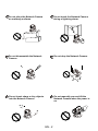
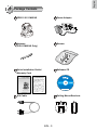
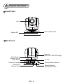
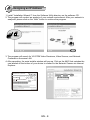
10x Zoom‧Multiple Streams‧PoE
PZ8111/21/11W/21W
This guide describes the basic functions of PZ8111/21/11W/21W.
All detailed information is described in the user’s manual.
P/N: 625015200G Ver.1.0
Copyright c 2011 VIVOTEK INC. All rights reserved.
English
Warning Before Installation
Power off the Network Camera
assoon as smoke or unusual odors
are detected.
Keep the Network Camera
away from water. If the Network
Camera becomes wet, power off
immediately.
Contact your distributor in the event of
occurrence.
Refer to your user’s manual for the
operating temperature.
Do not place the Network Camera
around heat sources, such as a
television or oven.
Power
Contact your distributor in the event of
occurrence.
/MIC
Activity
Powe
r/MIC
Activity
Keep the Network Camera away
from direct sunlight.
Powe
Do not place the Network Camera
in high humidity environments.
r/MIC
Activity
Powe
r/MIC
Activity
EN - 1
Do not place the Network Camera
on unsteady surfaces.
Power
Do not touch the Network Camera
during a lightning storm.
/MIC
Activity
Powe
r/MIC
Activity
Do not disassemble the Network
Camera.
Do not drop the Network Camera.
Activ
Power/
Powe
ity
MIC
r/MIC
Activity
Do not insert sharp or tiny objects
into the Network Camera.
Do not manually pan and tilt the
Network Camera when the power is
on.
Powe
r/MIC
Activity
Powe
r/MIC
Activity
EN - 2
English
1
Package Contents
Power Adapter
PZ8111/21/11W/21W
Pow
er/M
IC
Activity
Antenna
(PZ8111W/21W Only)
Screws
Quick Installation Guide /
Warranty Card
Software CD
510000202G
Ceiling Mount Brackets
A/V Cable
EN - 3
2
Physical Description
Front Panel
Lens
Status LED
Power/MIC
Activity
Built-in Microphone
Back Panel
Antenna
(PZ8111W / PZ8121W Only)
Microphone In
Ethernet 10/100
RJ45 Socket
AV Out
Power cord socket
AV
e e
General I/O
Terminal Block
Recessed Reset Button
External/Internal
Microphone Switch
EN - 4
English
3
Hardware Installation
Mounting the Network Camera
1. Attach ceiling mount bracket A to the Network Camera and secure it with two small
screws.
2. Drill three pilot holes into the ceiling; hammer the plastic anchors into the holes.
3. Fasten ceiling mount bracket B to the ceiling with three screws.
4. Slide the Network Camera into ceiling mount bracket B.
5. Secure ceiling mount bracket A and B with a small screw.
2
4
1
A
3
5
B
2
EN - 5
4
Network Deployment
General Connection (without PoE)
1. If you have external devices such as sensors and alarms, connect them to the general
I/O terminal block.
2. Connect the camera to a switch via Ethernet cable.
3. Connect the supplied power cable from the camera to a power outlet.
3
1
1: Power
2: Digital output
3: Digital input
4: Ground
AV
e e
POWER
COLLISION
1
2
3
4
5
LINK
RECEIVE
PARTITION
2
Ethernet Switch
EN - 6
English
Power over Ethernet (PoE)
When using a PoE-enabled switch
This Network Camera is PoE-compliant, allowing transmission of power and data via
a single Ethernet cable. Follow the below illustration to connect the camera to a PoE e
abled switch via Ethernet cable.
AV
e e
PoE switch
POWER
COLLISION
1
2
3
4
LINK
RECEIVE
PARTITION
5
When using a non-PoE switch
Use a PoE power injector (optional) to connect between the Network Camera and a
non-PoE switch.
AV
e e
PoE Power Injector
(optional)
POWER
COLLISION
1
2
3
4
5
LINK
RECEIVE
PARTITION
Non-PoE Switch
EN - 7
5
Assigning an IP Address
1. Install “Installation Wizard 2” from the Software Utility directory on the software CD.
2. The program will conduct an analysis of your network environment. After your network is
analyzed, please click on the “Next” button to continue the program.
IW2
Installation
Wizard 2
3. The program will search for VIVOTEK Video Receivers, Video Servers, and Network
Cameras on the same LAN.
4. After searching, the main installer window will pop up. Click on the MAC that matches the
one labeled on the bottom of your device to connect to the Network Camera via Internet
Explorer.
Network Camera
172.16.7.13
PZ8111W
0002D10766AD
0002D10766AD
RoHS
EN - 8
PZ71X2
PZ81X1
English
6
Ready to Use
1. Access the Network Camera on the LAN.
2. Retrieve live video through a web browser or recording software.
For further setup, please refer to the user's manual on the software CD.
EN - 9
7
Configure the Wireless Connection (PZ8111W/21W only)
1. Check the SSID for your wireless access point (AP).
2. Go to the PZ8111W/21W's Configuration page > Advanced mode > Wireless LAN.
3. Type in the SSID the same as your AP.
4. Select the Wireless mode as "Infrastructure".
5. Click Save. The Network Camera will reboot.
6. Wait for the live image to be reloaded to your browser. Then, unplug the power cable and
Ethernet cable from the Network Camera.
7. Replug the power cable to the camera. The Network Camera will now operate in wireless
mode.
ADSL/Ca
ble/Hub
AV Out
e e
PZ8111W/21W
AP
POWER
COLLISION
1
2
3
4
5
LINK
RECEIVE
PARTITION
Note
1. SSID, abbreviated from Service Set Identifier, is the name assigned to the wireless
network. The PZ8111W/21W factory SSID setting is set to "default".
2. Select "Ad-Hoc" wireless mode if you want the PZ8111W/21W to communicate without
using an AP or wireless router.
For further setup, please refer to the user's manual on the software CD.
EN - 10
10x Zoom‧Multiple Streams‧PoE
PZ8111/21/11W/21W
This guide describes the basic functions of PZ8111/21/11W/21W.
All detailed information is described in the user’s manual.
P/N: 625015200G Ver.1.0
Copyright c 2011 VIVOTEK INC. All rights reserved.


![Cover [PZ81x1,x1W].ai](http://vs1.manualzilla.com/store/data/006040535_1-42ed705d921c196e7271c308c8c31f51-150x150.png)


![Cover [IP8331]_Outline](http://vs1.manualzilla.com/store/data/006291669_1-58e4b2a382cb6b9ba21df6b07dfb0c67-150x150.png)