1
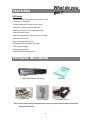
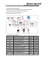
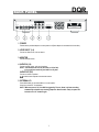
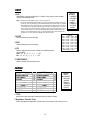
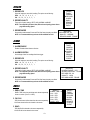
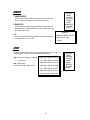
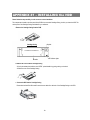
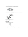
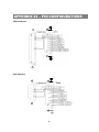
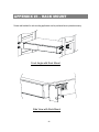
4 CH Digital Quad Recorder
VT-DVR04Q
Please read this instructions thoroughly before operation and retain it
for future reference.
User Manual V 1.0
DQR
WARNING
All the safety and operating instructions should be read before operation. The improper operation may cause
permanent damage.
‧ Please use the adaptor provided from VITEK (Other adaptor is not suitable for this machine).
‧ Please lift and place this equipment gently.
‧ Do not expose this equipment to open sunlight.
‧ Do not use this equipment near water or in contact with water.
‧ Do not spill liquid of any kind on the equipment.
‧ Please power off the unit before unplugging.
‧ Do not switch the Power On & Off within short period of time (within 3 seconds).
‧ Do not attempt to service this equipment by yourself.
‧ Installation should be made by qualified service personnel.
The lightning flash with arrowhead symbol, within an equilateral triangle, is intended to alert
the user to the presence of uninsulated "dangerous voltage" within the product's enclosure that
may be of sufficient magnitude to constitute a risk of electric shock to persons.
The exclamation point within an equilateral triangle is intended to alert the user to the presence
of important operating and maintenance-(servicing) instructions in the literature accompanying
the appliance.
1
TABLE OF CONTENTS
DQR
What do you get ?
‧ FEATURES ----------------------------------------------------------------------------------------
3
‧ PACKAGE INCLUDING ------------------------------------------------------------------------
3
Before Operation
‧ INSTALLATION GUIDE ------------------------------------------------------------------------
4
‧ FRONT PANEL -----------------------------------------------------------------------------------
5
‧ BACK PANEL -------------------------------------------------------------------------------------
7
Basic Operation
‧ START THIS UNIT --------------------------------------------------------------------------------
8
‧ OPERATION ----------------------------------------------------------------------------------------
8
Detailed Menu Setup
‧ ACCESS MENU ----------------------------------------------------------------------------------
10
‧ MAIN MENU ---------------------------------------------------------------------------------------
10
‧ MENU OPTIONS ---------------------------------------------------------------------------------
11
Advanced Operation
‧ OPERATION OPTIONS ------------------------------------------------------------------------
15
‧ KEY LOCK ----------------------------------------------------------------------------------------
16
‧ RS-232 PROTOCOL ----------------------------------------------------------------------------
16
Trouble Shooting ---------------------------------------------------------------------------------- 16
Specifications -------------------------------------------------------------------------------------- 17
APPENDIX #1 – INSTALLING THE HDD ---------------------------------------------------- 18
APPENDIX #2 – PIN CONFIGURATIONS --------------------------------------------------- 20
APPENDIX #3 – RACK MOUNT ---------------------------------------------------------------- 22
APPENDIX #4 – RECORDING SPEED ------------------------------------------------------- 23
2
What do you
get ?
FEATURES
DQR Features
• Wavelet Compression Format replaces Time-Lapse VCR + Quad
• 4 Audio inputs / 2 Audio outputs
• On Screen Display and RTC (Real time clock) Function
• Support from 1 channel to 4 channels video inputs
• Digital Zoom can be up to 2 X 2 in DQR playback modes
• Alarm Input & Output Function
• Video loss detected on each channel can record up to 64 events
• Power-loss memory function
• Support 1 Removable HDD, IDE Type
• Quick Multiple Search by date/time, alarm, full list
• Timer : Schedule recording
• Security password protection
• RS-232, RS-485 communication protocol
PACKAGE INCLUDING
Digital Quad Recorder(with HDD cartridge)
Accessories pack
User Manual
2 Keys for Cartridge
Power Adapter and Cord
NOTE : Please check the package to make sure that you receive the complete accessories which includes those
components shown above.
3
INSTALLATION GUIDE
Before Operatio
1. Connect cameras and monitor with the DQR.
2. Shown below is one example for connecting the DQR to your existing Observation System.
3. Install HDD (The compatible HDD Brands are listed in the following table.)
Please refer to page.18 Appendix #1 for installation instructions.
The HDD must be installed before turning on the DQR.
COMPATIBLE HARD DISK BRANDS
Manufacturer
HITACHI
IBM
IBM
IBM
IBM
Maxtor
Maxtor
Maxtor
Seagate
Seagate
Seagate
Western Digital
Western Digital
Western Digital
Model
Deskstar 180 GXP (120 GB)
Deskstar 120GXP (40GB)
Deskstar 60GXP IC35l060
Deskstar 120GXP (80GB)
Deskstar 120GXP (120GB)
DiamondMax 536DX(60GB) 4W060H4
DiamondMax Plus 9
DiamondMax Plus 9, Model#6Y120L
Barracuda ATA IV ST340016A
Barracuda ATA V, ST3120023A
Barracuda ATA IV, ST380021A
Caviar WD400BB-00BSA0
Caviar WD400EB-00CPF0
Caviar WD1200BB-00CAA1
4
Capacity
120GB
40GB
60GB
80GB
120GB
60GB
80GB
120GB
40GB
120GB
80GB
40GB
40GB
120GB
Rotation
7200rpm
7200 rpm
7200 rpm
7200 rpm
7200 rpm
7200rpm
7200 rpm
7200 rpm
7200 rpm
7200 rpm
7200rpm
7200 rpm
5400 rpm
7200rpm
DQR
FRONT PANEL
PAUSE / Up
HDD
F u ll
A L A RM
TIM ER
P L AY
RE C
A UT O
FF
Right
REW
Left
MENU
ENTER
SEARCH
SLOW
AUTO
REC
POWER
QUAD
STOP / Down
1. REMOVABLE HDD CARTRIDGE
Please refer to page.18 Appendix #1.
2. MENU
Press MENU to enter main menu.
3. ENTER
Press ENTER for confirmation.
4. SEARCH
Press SEARCH for searching recording video.
5. SLOW
To slow down speed of play mode.
6. STOP / Down
‧STOP : Under DQR Record / Play mode, it can stop the moment action.
‧DOWN : Under setup mode, it works as Down button.
7. REC
Press REC to start recording.
8. POWER
Press Power to turn ON / OFF the DQR.
9. REW / Left
‧REW : Under DQR play mode, it can play video backward at different speeds. (Press REW again to adjust
speed as 1, 2, 4, 8, 16, 32 times)
‧Left : Under setup mode, it works as Left button.
10. FF / Right
‧FF : It can play video forward at high speed, and press FF again to adjust speed from 1, 2, 4, 8, 16, 32 times.
‧Right : Under setup mode, it can work as Right button.
5
11. PAUSE / Up
‧Pause : Under DQR play mode, it can pause the action.
‧UP : Under setup mode, it works as Up button.
12. PLAY
Press PLAY to playback recorded video.
13. LED LIGHT
The LED Light is ON under following condition.
‧HDD Full : HDD is full
‧ALARM : If Alarm Enable sets as “YES”, while the alarm is triggered , the led will be flashing
‧TIMER : When Timer is set as Enabled
‧PLAY : On Play mode
‧REC : On Recording mode
‧AUTO : 4 channel will display in full screen by turns
14.
: Displays the CH1 camera
: Displays the CH2 camera
: Displays the CH3 camera
: Displays the CH4 camera
QUAD : Display 4 cameras in Quad screen format
AUTO : 4 channel will display in full screen format by turns
6
DQR
BACK PANEL
IN
OUT
MONITOR
PO W E R
V IDEO 1
2
3
1
3
R
2
4
L
EXTERNAL I/O
RI SK O F ELECTRI C SHO CK
D O NOT O PE N
WAR NING : TO REDUCE THE RISK OF ELECTRIC SHOCK,
DO NOT REMOVE COVER (OR BACK).
NO USER-SERVICEABLE PARTS INSIDE.
REFER SERVICING TO QUALIFIED
SERVICE PERSONNEL.
4
1. POWER
Please use the provided adaptor to connect power cord (Other adaptor is not suitable for this machine).
2. VIDEO INPUT (1-4)
Connect to video source, such as camera
3. MONITOR
Connect to Main monitor
4. AUDIO IN (1-4)
Connect to audio source, such as microphone
NOTE : 1.IPS should be set over 30 (for NTSC) or 25 (for PAL)
2.You could just record only one Audio in every time.
AUDIO OUT (R/L)
Connect to monitor or speaker.
✻ with 2 mono audio outputs from the same source.
5. EXTERNAL I/O
‧Controlled remotely by an external device or control system.
‧Alarm input, external I / O explanation.
NOTE : While the power is off, if the DQR is triggered by Timer or Alarm, it will start recording
automatically and while stop recording (depend on Alarm Duration Time), the power will
be back to the “off” situation again.
7
Basic Operation
START THIS UNIT
Before using the DQR, please have a HDD installed ready. (refer to Appendix #1 for installation or removal of a HDD).
1. Connect the AC Power Cord with Power Adapter and plug into an electrical outlet. The Red LED indicator light will be
ON and the DQR is in Standby mode.
2. Press the Power button. The POWER LED will turn from red to orange, and other red LED indicators will turn ON. It
takes approximately 5 to 15 seconds to boot the system with the message : “ HDD Detecting ”. Once connected, the
POWER LED will change to green color, and the Alarm and Timer LED will be ON.
3. Before operating the DQR, please set up the system time first. (for setting system time, please refer to page.11).
NOTE : When “HDD not found” message shows up, please refer to appendix # 1. As the HDD is likely not
installed correctly.
OPERATION
RECORDING
The DQR offers a variety of recording modes, such as record continuously, at scheduled time, and by events. You can set
up recording speed and resolution. You can set these options by selecting MENU / RECORD before recording, please
refer to page.13. Under the recording status, if power is off accidentally, recorded video will still store in the HDD. DQR
will return to original recording situation after power returns again.
On the screen, you will find the date, time, HDD recording type, the amount of available GB left in the HDD memory and
the letter “A” represents the method of recording that is occurring.
(OW : HDD Overwrite)
NOTE : When the HDD is full under O/W Recording mode, previous recorded files 2002 – JAN –01 01:02:03
A●OW
may be overwritten without further warning notices.
There are 4 recording modes in which Recording can occur : Alarm, Timer, Manual and External Record.
1. ALARM RECORD
When DQR is triggered by an alarm input, it will record immediately. Indicated by the letter “A” and show
on the triggered channel.
2. TIMER RECORD
When recording is scheduled by a Timer. Indicated by the letter “T”.
3. MANUAL RECORD
When recording is initiated by manually pressing the REC button. Indicated by the letter “M”.
4. EXTERNAL RECORD
When recording is triggered by an External device. Indicated by the letter “E”.
8
!
diagram
PLAY
Press “ PLAY ” button, the DQR will show the last recording.
1. FAST FORWARD (F.F. ) & FAST REWIND (F.R.)
You can increase the speed of Fast Forward and Rewind on the DQR.
In the Play mode, press ” ►► ” once to get 2X speed forward and press twice to get 4X speed,… and the maximum
speed can reach 32X.
Press ”◄◄ ” once to get 1X speed rewind and press twice to get 2X speed, … and the maximum speed can reach
32X.
2. SLOW FORWARD (S.F.) & SLOW REWIND (S.R.)
You can also slow down the speeds of Forward and Rewind on the DQR.
In the Play mode, press the SLOW button and you will enter Slow mode.
Press ” ►► ” once to get 1/2X speed forward and press twice to get 1/4X speed,… and the slowest speed can reach
1/32X.
Press ”◄◄ ” once to get 1/2X speed rewind and press twice to get 1/4X speed, … and the slowest speed can reach
1/32X.
3. PAUSE
It will let you pause the current image displayed on the screen.
4. STOP
Press “ STOP ” under any circumstance, it will return DQR to live monitoring mode.
5. IMAGE JOG DIAL
It will allow you to manually view video frame-by-frame, one image at a time.
While in PLAY mode, press “ PAUSE ”, it will pause the screen.
Pressing “ ►► ” button advances the frozen screen one image forward.
Pressing “ ◄◄ ” button moves back one image.
9
Detailed Menu
Setup
ACCESS MENU
The Menu allows you to configure your DQR settings. Please follow below
steps to access the Menu :
Password: 0000
Press the Menu button. The password screen will appear:
NOTE : The default Password is 0000. Simply press the Enter button to access the Menu.
To key-in the Password, press the “Right” and “Left” buttons to move between numbers, and use the “Up”
and “Down” buttons to input the number.
Press the ENTER button once the correct Password is entered. The MENU options screen will appear.
Note: If you get a message “Password Error”, you have entered an incorrect password.
MAIN MENU
There are 8 options available in the Main Menu:
(MENU)
►TIMER
CAMERA
RECORD
ALARM
DWELL
REMOTE
SYSTEM
EVENT
TIMER ---------- Scheduling Record
CAMERA ------- Camera Channel Setup
RECORD ------- Record Mode Setup
ALARM---------- Alarm Mode Setup
DWELL---------- Auto channel switching setup
REMOTE-------- Remote control protocol Setup
SYSTEM -------- System Setup
EVENT ---------- Event List
Outlined below are the buttons used for Menu setting :
‧“Up” and “Down” : Scroll up and down or change values when an option is selected and is blinking
‧“Left” and “Right” : Scroll sideways within a menu option that has been selected
‧ENTER : Selects a submenu / an option under a submenu for browsing / modification
‧MENU : Completes modification of a menu option; exits a menu
10
DQR
MENU OPTIONS
SYSTEM
1. AUDIO INPUT
To choose one of 4 channels to record. (only can select 1 during operation for recording)
2. BUZZER
While you set the BUZZER as “ON”, it will be triggered by event occurrence.
3. HDD OVERWRITE
Select “YES” to overwrite previous recording video in HDD.
NOTE : When the HDD is full under O/W Recording mode, previous recorded files
may be overwritten without further warning notices.
(MENU)
TIMER
CAMERA
RECORD
ALARM
DWELL
REMOTE
► SYSTEM
EVENT
4. MESSAGE LATCH
To select whether the DQR messages will disappear after 10
sec or remain on screen. NO is the default setting which the
messages will go away after 10 sec.
NOTE : Video loss message will be showed the same as Alarm
Duration time.
5. DATE DISPLAY
To set the Date mode showed on the monitor.
6. DATE
To set the system date on the DQR.
(SYSTEM)
► AUDIO INPUT : 1
BUZZER : ON
HDD OVERWRITE : NO
MESSAGE LATCH : NO
DATE DISPLAY : Y-M-D
DATE : 2003-JAN-02(THU)
TIME : 01:41:23
NEW PASSWORD : XXXX
CLEAR HDD : NO
SYSTEM RESET : NO
7. TIME
To set the system time on the DQR.
8. NEW PASSWORD : XXXX (Default password : 0000)
ALL DATA IN HDD
WILL BE CLEARED
To set the new password.
ARE YOU SURE?
(◄ : NO ► : YES )
9. CLEAR HDD
Delete all the contents of your HDD. When you choose “YES” on this option, you will be prompted with the
question shown : Press “►” to clear HDD or press ”◄” to confirm not to clear HDD.
10. SYSTEM RESET
Reset all system settings to book to factory default settings.
11
TIMER
1. DAY
Select the day, or days of the week (Mon–Fri / Sat-Sun / Daily) that you wish to schedule
the DQR to automatically record.
NOTE : 1.Special Date could be changed by “Enter”, “Up” and “Down” buttons.
2. If you have selected the specific date and recording timer set from that specific day to
a new day, then the Recording Timer Schedule will be set as whole week. For specific
date of Recording Timer Schedule, it is not recommended to set End Time over 23:59.
For Example:If you set Timer Schedule Day as Sunday, and START from 11:30, but
End on 00:20, then Recording Timer Schedule is set as from every Sunday's 11:30 to
next Sunday's 00:20. If you only want to set Recording Timer Schedule from every
Sunday 11:30 to Monday 00:20, then you should set Recording Timer Schedule as
Sunday from 11:30 to 23:59, and Monday from 00:00 to 00:20.
2. START
Select the starting time for the recording.
3. END
Select the finishing time for the recording.
4. IPS
Stand for Images Per Second and it could let you see Record submenu
for more details.
NTSC-60、30、15、8、4、2、 1、OFF
PAL-50、25、12、6、3、2、 1、OFF
(MENU)
►TIMER
CAMERA
RECORD
ALARM
DWELL
REMOTE
SYSTEM
EVENT
(TIMER)
DAY START END IPS
DAILY 00:00 00:00 OFF
DAILY 00:00 00:00 OFF
DAILY 00:00 00:00 OFF
DAILY 00:00 00:00 OFF
DAILY 00:00 00:00 OFF
DAILY 00:00 00:00 OFF
DAILY 00:00 00:00 OFF
DAILY 00:00 00:00 OFF
TIMER ENABLE : YES
5. TIMER ENABLE
Enables / Disables Timer recording function
CAMERA
_ _ _ CH1_ _ _ _
_ _ _ CH2_ _ _ _
: 5 BRIGHTNESS
:5
BRIGHTNESS
CONTRAST
: 5 CONTRAST
:5
COLOR
: 5 COLOR
:5
_ _ _ CH3_ _ _ _
_ _ _ CH4 _ _ _
BRIGHTNESS
: 5 BRIGHTNESS
CONTRAST
: 5 CONTRAST
COLOR
: 5 COLOR
:5
:5
:5
(MENU)
TIMER
►CAMERA
RECORD
ALARM
DWELL
REMOTE
SYSTEM
EVENT
1. TITLE
Assign a title to each camera input. Initially each title is the camera’s number.
2. Brightness / Contrast / Color
Have a video adjustment (Brightness / Contrast / Color) of each channel. The level is from 0 to 9.
12
RECORD
1. RECORD IPS
Select the images per second of recording. The options are as following :
NTSC-60、30、15、8、4、2、 1
PAL-50、25、12、6、3、2、 1
2. RECORD QUALITY
There are four quality settings : BEST, HIGH, NORMAL and BASIC.
NOTE : The relationship of Record time, IPS and record quality, please refer to
page.23 Recording Speed.
(MENU)
TIMER
CAMERA
►RECORD
ALARM
DWELL
REMOTE
SYSTEM
EVENT
3. RECORD MODE
(RECORD)
Set recording mode between Frame and Field. One frame is equal to two fields. ►RECORD IPS : 60
NOTE : It is recommended that you leave the Record Mode as Field.
QUALITY : NORMAL
RECORD MODE : FRAME
ALARM
(MENU)
TIMER
CAMERA
RECORD
►ALARM
DWELL
REMOTE
SYSTEM
EVENT
1. ALARM ENABLE
Enables / Disables Alarm feature to function.
2. ALARM DURATION
Set the length of time for recording after Alarm trigger.
3. RECORD IPS
Select the images per second of recording. The options are as following :
NTSC-60、30、15、8、4、2、 1
PAL-50、25、12、6、3、2、 1
4. RECORD QUALITY
(RECORD)
There are four quality settings : BEST, HIGH, NORMAL and BASIC.
► ALARM ENABLE : YES
NOTE : The relationship of Record time, IPS and record quality, please refer to
ALARM DURATION : 10 SEC
page.23 Recording Speed.
RECORD IPS : 60
QUALITY : HIGH
RECORD MODE : FRAME
5. RECORD MODE
Set recording mode between Frame and Field. One frame is equal to two fields.
NOTE : It is recommended that you leave the Record Mode as Field.
DWELL
1. DWELL TIME
(DWELL)
DWELL TIME is the time period that each channel sequentially ►DWELL TIME : 02
CH1 : YES
shown on monitor. (From 01-10 SEC)
CH2 : YES
CH3 : YES
2. CH1-CH4
CH4 : YES
YES-Chose channel will be showed on the screen sequentially.
QUAD : YES
NO-Chose channel will not be showed on the screen.
3. QUAD
YES-QUAD will be showed on the screen sequentially.
NO-QUAD will not be showed on the screen.
13
(MENU)
TIMER
CAMERA
RECORD
ALARM
►DWELL
REMOTE
SYSTEM
EVENT
REMOTE
(MENU)
TIMER
CAMERA
RECORD
ALARM
DWELL
►REMOTE
SYSTEM
EVENT
1. REMOTE MODE
Select RS-232 or RS-485 interface for the remote computer connection
Protocol. (Please refer to page.16 for RS-232 Remote Protocol)
2. BAUD RATE
Set the speed of the remote computer’s Baud Rate – which is the rate of
Data transmission. Available Baud Rate are 115200, 57600, 19200, 9600,
4800, 3600, 2400 and 1200.
(REMOTE)
3. ID
Allow you to use RS-232 or RS-485 protocol to program different DQRs.
The range of ID is from “000” to “255”.
►REMOTE MODE: RS-232
BAUD RATE: 9600
ID: 000
EVENT
The recorded events will be showed on a single page and please press “◄ ” or “► ” to
change the pages. An “Event” occurs when following incidents occur :
PWR : Recovery time after power shut down
PWR 2002-JAN-01 03:00:00
in record mode
1VL 2002-JAN-01 01:02:04
HDD : HDD error time
HDD 2002-JAN-01 01:02:03
1VL / 2VL / 3VL / 4VL : Video loss time
PWR 2002-JAN-01 01:02:02
2VL 2002-JAN-01 01:02:01
HDD 2002-JAN-01 01:02:00
◄: Page Up ►: Page Down
14
(MENU)
TIMER
CAMERA
RECORD
ALARM
DWELL
REMOTE
SYSTEM
►EVENT
OPERATION OPTIONS
Advanced
Operation
VIDEO LOSS
Screen will display
X
if the video input is not connected properly.
SEARCH
1. LAST RECORD
►LAST RECORD
FULL LIST
ALARM LIST
TIME SEARCH
Play the last recorded video.
2. FULL LIST
Show a listing of all recorded video on the HDD which sorted by time.
M : Manual Record time
A : Alarm Record time
T : Timer Record time
E : External Record time
3. ALARM LIST
Show a listing of all recorded video triggered by an Alarm.
NOTE : If there are no Alarm in the record, the screen will
display “EMPTY”.
►M 2002-JAN-02 01:02:03
M 2002-JAN-01 05:02:03
A 2002-JAN-01 04:02:03
T 2002-JAN-01 03:02:04
T 2002-JAN-01 02:02:03
M 2002-JAN-01 01:02:01
◄: PAGE UP►: PAGE DOWN
4. TIME SEARCH
Find video recorded on a specific date that is entered.
CAMERA SELECT (1-4)
Press
to select appointed camera to display on full screen mode.
QUAD&AUTO
Press “QUAD” button to display 4 cameras in Quad screen format
Press “AUTO” button to display 4 channels and Quad mode in full screen format by turns
15
DQR
KEY LOCK
For added security, you can “Lock” all buttons on your DQR. Locking disables the buttons and prevents other people from
using the system.
Press ENTER and MENU at the same time to enable Key Lock.
Press ENTER and MENU at the same time to disable Key Lock.
RS-232 REMOTE PROTOCOL
You can use the PC keyboard to simulate DQR keypad.
DATA : REMOTE PROTOCOL using 8 bit data、1 start bit、1stop bit
FUNCTION CODE ASCII FUNCTION CODE ASCII
MENU
ENTER
Search
Slow
Up
Down
Left
Right
0x4D
0x0D
0x48
0x53
0x55
0x4E
0x4C
0x52
M
ENTER
H
S
U
N
L
R
PLAY
REC
CH1
CH2
CH3
CH4
QUAD
AUTO
0x50
0x72
0x31
0x32
0x33
0x34
0x51
0x41
P
r
1
2
3
4
Q
A
TROUBLE SHOOTING
When malfunction occurs with DQR, it may be not serious and can be corrected easily. The table below describes some
typical problems and their solutions. Please check them before calling your DQR dealer.
PROBLEM
HDD Not Found
z
SOLUTION
Please Insert HDD
z
Please use the Key to lock the HDD Cartridge
z
Check power cord connections.
z
Confirm that there is power at the outlet.
Not working when
press any button
z
z
Check if it is under Key Lock mode.
Press "MENU" & "ENTER" to exist Key Lock mode.
No recorded video
z
Check if the HDD is installed properly.
Timer Record enable
does not working
No live video
z
Check if the Record Enable is set to YES
z
Check camera video cable and connections.
z
Check monitor video cable and connections.
z
Confirm that the camera has power.
z
Check camera lens setting.
And press any key
No power
16
DQR
SPECIFICATIONS
Video format
Hard disk storage
Record mode
Camera Input Signal
Main Monitor Output
Audio input
Audio output
Video Loss Detection
Refresh Rate
Recording Rate
NTSC/EIA or PAL/CCIR
IDE type, UTMA 66 above, 1 removable HDD supported
Manual / Alarm / Timer / External
Composite video signal 1 Vp-p 75Ω BNC, 4 channels
Composite video signal 1 Vp-p 75Ω BNC
4 audio inputs, (RCA) *
2 audio outputs, (RCA) **
Yes
60 images/sec. for NTSC / 50 images/sec. for PAL
60 images/sec. for NTSC / 50 images/sec. for PAL
Dwell Time
Programmable (1~10 Sec)
Yes
2*2 (Digital Zooming)
Key Lock
Picture Zoom
Camera Title
Video Adjustable
Alarm Input
Alarm Output
Remote Control
Time Display Format
Power Source
Power Consumption
Operation Temperature
RS-232C / RS-485 (bps)
Dimension (mm)
Net Weight
10 letters
Color/ Contrast/ Brightness Adjustable
TTL input, Hi (5V), Low (GND)
COM / N.O / N.C
RS-232 or RS-485
YY/MM/DD, DD/MM/YY, MM/DD/YY, OFF
AC90~240V + 10% switching adaptor
<27W
10 ~ 40 ℃
115200 、 57600 、 19200 、 9600 、 4800 、 3600 、 2400 、 1200
380(W) x 270(L) x 65(H)
5.2 k gs
Specifications are subject to change without notice.
✻ 4 audio inputs, but only can select 1 during operation for recording
✻ ✻ with 2 mono audio outputs from the same source.
17
APPENDIX #1 – INSTALLING the HDD
Please follow the steps carefully in order to ensure correct installation.
The compartment located on the front panel of the DQR is the removable Cartridge Casing, in which you insert the HDD. The
various parts of the Cartridge Casing are labeled for your reference.
1.Remove the Cartridge Casing from the DQR
Keyhole
Cartridge Casing
LED indicator lights
Handle
2. Remove the Cover from the Cartridge Casing
Æ Unclip the release latch with the word “OPEN” printed beside it by gently pushing on the latch.
Æ Slide the cover off the Cartridge Casing.
3. Connect the HDD into the Cartridge Casing
Please take the Hard Disk Drive and Connect the two cables from the back of the Cartridge Casing to the HDD.
18
4. Secure the HDD in the Casing (optional)
Use the screws supplied to tighten them, place the HDD into correct position.
5.Slide the top Cover over the Cartridge Casing
Slide the Cover forward over the Cartridge Case. Ensure it is secured in place over the release latch.
6.Reinsert the Cartridge Casing into the DQR
Fully insert the Cartridge Case into the DQR.
7. Lock the Cabinet
Lock the cabinet by turning the key clockwise.
A
(locked)
B
(unlocked)
Note : If you do not lock the cabinet, the DQR system will not function properly.
19
APPENDIX #2 – PIN CONFIGURATIONS
25 pin com port
‧
‧
‧
‧
9 pin com port
‧
‧
DQR
‧
‧
20
PIN 1. RS232-TX : RS-232
DQR can be controlled remotely by an external device or control system, such as a control keyboard, using RS232 serial communications signals.
PIN 2. RS232-RX : RS232
DQR can be controlled remotely by an external device or control system, such as a control keyboard, using RS232 serial communications signals.
PIN 3, 4, 5, 6 ALARM INPUT
To connect wire from ALARM INPUT (PIN 3, 4, 5, 6) to GND ( PIN 9 ) connector, DQR will start recording and
buzzer will be on. When alarm has been triggered, signal becomes “Low”, and it will stop all alarm activities.
Under normal operation, signal remains “High”.
PIN 7. EXTERNAL ALARM NC
Under normal operation COM connect with NC and disconnect with NO. But when alarm triggered, COM
disconnect with NC, and connect with NO.
PIN 8. EXTERNAL ALARM NO
Under normal operation, COM will disconnect from NO. But when Alarm triggered, COM will connect with NO.
PIN 9. GND
GROUND
PIN 10. RS485-B
DQR can be controlled remotely by an external device or control system, such as a control keyboard, using
RS485 serial communications signals.
PIN 11. RS485-A
DQR can be controlled remotely by an external device or control system, such as a control keyboard, using
RS485 serial communications signals.
PIN 12. DISK FULL (OUTPUT)
When HDD is full, it sends a signal to trigger next DQR record mode, if you install another DQR. Under normal
operation, the signal remains “High”. But when disk full, DQR will send the “Low” signal.
PIN 13. REC START (INPUT)
This pin can accept the external trigger signal to activate record mode from external device. When the external
signal turn to “Low”, it will trigger DQR record mode. When the external signal back to “High”, it will stop recording
action. The default normal operation remains “High”.
PIN 14. ALARM RESET (INPUT)
To connect wire from ALARM RESET ( PIN 14 ) to GND ( PIN 9 ) connector, it can disable ALARM. An external
signal to ALARM RESET ( PIN 14 ) can be used to reset both ALARM OUTPUT signal and DQR’s internal buzzer.
When alarm has been triggered, signal becomes “Low”, and it will stop all alarm activities. Under normal operation,
signal remains “High”.
PIN 15. EXTERNAL ALARM COM
Under normal operation COM connect with NC and disconnect with NO. But when alarm
triggered, COM disconnect with NC, and connect with NO.
21
APPENDIX #3 – RACK MOUNT
Screws and brackets for rack mounting applications can be purchased as an optional accessory.
Front Angle with Rock Mount
Side View with Rack Mount
22
APPENDIX #4 – RECORDING SPEED
The Record Time is different based on Record Speed and Record Quality. Please refer to following table.
NTSC SYSTEM
IPS
Best
Record High
Quality Normal
Basic
60
30
15
8
4
2
1
12hr
24hr
48hr
90hr
180hr
360hr
720hr
15hr
30hr
60hr
112.5hr
225hr
450hr
900hr
24hr
48hr
96hr
180hr
360hr
720hr
1440hr
40hr
80hr
160hr
300hr
600hr
120GB
1200hr
2400hr
50
25
12
6
3
2
1
12hr
24hr
50hr
101hr
203hr
304hr
608hr
15hr
30hr
63hr
127hr
253hr
380hr
760hr
24hr
49hr
101hr
203hr
405hr
608hr
1220hr
81hr
168hr
338hr
675hr
120GB
1013hr
2025hr
HDD Type
PAL SYSTEM
IPS
Best
Record High
Quality Normal
Basic
HDD Type
41hr
Note: Above data is obtained from actual test of recording normal TV program. (For
Reference Only)
23
Industrial Video Products, Inc.
9970 Glenoaks Blvd. Unit B Sun Valley, CA 91352
Phone: 888-VITEK-70 / 818-771-0300 Fax: 818-771-0400
WWW.VITEKCCTV.COM